filee. gariboldi, w. nicodemi, p. pellin, g. silva, m. vedani politecnico di milano, dipartimento di...
TRANSCRIPT
Some case histories of surface finish related failures
E. Gariboldi, W. Nicodemi, P. Pellin, G. Silva, M. Vedani
Politecnico di Milano, Dipartimento di Meccanica, Piazza L Da Vinci
32,7-20733 M&mo,
Abstract
Helical compression springs experienced occasional fatigue failures duringservice in cable transportation plants operating at relatively low temperatures.The springs were made of UNI 50CrV4 steel quenched and tempered to obtainhigh strength level. A high intensity shot-peening treatment gave rise to surfacedefects that acted as nucleation sites for fatigue cracks which rapidly propagatedin a material embrittled by a number of factors.
In a paper-mill plant, rolls failed in service after more than 10? cycles. Thecracks leading to these failures were nucleated at surfacial pits brought about byenvironmental corrosive attack. Propagation by fatigue developed in a ferritic-pearlitic microstructure that was not the most suitable condition to sustainfatigue loading.
1 Introduction
Following the observations drawn in a companion paper in these Proceedingswhich is dealing with the influence of material strength and surface conditionon fatigue properties of steels, the present contribution is aimed at givingpractical examples of premature fatigue failures due to the wrong selection ofsteel properties as well as surface conditions.
2 Fatigue failures of high-strength springs
A limited number of helical compression springs, installed on components forcable transportation plants had failed in service far before the end of their
Transactions on Engineering Sciences vol 8, © 1995 WIT Press, www.witpress.com, ISSN 1743-3533

210 Surface Treatment Effects II
expected life. The springs had operated under the designed loading conditionsand were in perfect agreement with the production specifications as far asgeometry, steel composition and microstructure were concerned. Even if thenominal shot-peening intensity stated by the manufacturer was in agreementwith the spring size (16 Almen A for a diameter of 14 mm), a careful analysisof the spring surfaces revealed the presence of microdefects, figure 1,associated with folds and ridges of the material produced by the shot-peeningprocess.
>>o .inls
Figure 2: Comparison of the surfaceroughness profiles of two shot peened
Figure 1: Surface defects detected on springs, (a) conventional spring,the shot-peened springs. RA= 1.85 jam; (b) abnormally shot-
peened spring, RA~ 5.00 p.m.
The defects appeared very pronounced when the surface was compared to thatof other helical springs more conventionally shot-peened at the same nominalintensity. Comparative roughness measurements carried out on the springsquantitatively supported the above observations. The roughness values weresystematically higher for the failed components, as can be observed by theexamples of roughness profiles depicted in figure 2.
Fractographs of the broken springs showed that nucleation of the cracks alwaysoccurred in the intrados region of the helices, which are the most stressed partswhen the springs were compressed. The cracks initially developed on flatsurfaces oriented along the bar axis. After an initial extension, variable in sizedepending on the spring examined, the cracks grew along helical surfacesperpendicularly to the normal tensile stress direction as shown in figure 3. Thisbehaviour was typical of crack extension in cylindrical bars under torsion withthe presence of surfacial compressive layers [1,2].
Transactions on Engineering Sciences vol 8, © 1995 WIT Press, www.witpress.com, ISSN 1743-3533

Surface Treatment Effects II 211
Excluding other particular defects related to the surface condition of the springssuch as the presence of a decarburised layer or of seams, the evidences offatigue microcracks were accounted for by the surfacial roughness andmicroflaws caused by the anomalous shot-peening process. As suggested infigure 4, the surface condition and the material properties were such that crackgrowth started at the surfacial tearing regions and folds favourably orientedwith respect to the stress direction.
Figure 3: Macroscopic view of the Figure 4: Microcrack nucleated fromfracture surface of a spring failed in a surface defect.service.
Figure 5: Intergranular fracture sur-face of a broken spring.
Figure 6: Mixed (quasi-cleavage andintergranular) fracture surface of aspring failed at room temperature
From a microstructural point of view, the fractographic analyses of the springsfailed in service, whose temperature at the time of breakage was unknown,always featured an intergranular separation, as depicted in figure 5.
Transactions on Engineering Sciences vol 8, © 1995 WIT Press, www.witpress.com, ISSN 1743-3533
2 1 2 Surface Treatment Effects II
In addition to the fractographic exams on springs, a fatigue test was carried outat room temperature on a part of a spring formerly failed in service. Thissample failed after about 10^ further cycles at a stress comparable to theoriginal design stress. In this case the fracture surface was of different type,mostly of quasi-cleavage mode with some occasional intergranular decohesionsas depicted in figure 6. The difference in the latter fracture mode with respectto that typical of service failures (figure 5) suggests the marked role played bythe environmental low temperature on fatigue failures in service.
18001700-
-m 1600-CL2, 1500-
6 i«°°-lzUJ 1300-05 1200
1100-
S-
MPACT ENERGT
45-40-
3025-20-1510-
n-
...
; 40 HRC
_^ ~~̂i>̂'*'̂ i 45 HRC
•30 -20 -10 0 10 20 30 40TEMPERATURE (C)
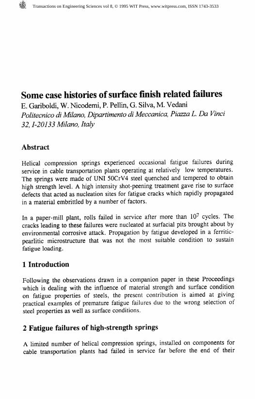
Figure 1: Tensile data of the 50CrV4steel as a function of temperature.
-20 0 20 40 60 80 100 120 140TEMPERATURE (C)
Figure 8: Transition curves (KV-notch impact energy) of the 50CrV4steel.
The mechanical behaviour of the 50CrV4 steel was studied by the authors in thetemperature range -40 *C +20°C and in two different tempers (correspondingto nominal hardness values of 40 HRC and 45 HRC) in a research on the low-temperature properties of some spring steels [3]. As expected, the lower testtemperatures improved the ultimate tensile strength and the 0.2% yield strengthaccording to the data given in figure 7. In the examined temperature range noremarkable changes in tensile ductility were detected. Further data on theresistance to dynamic loading and on the effect of the test temperature areobtainable by the transition temperature curves (KV-notch Charpy impactenergies vs. temperature) shown in figure 8. These curves illustrate the brittlebehaviour of the 50CrV4 steel tempered at both 465 °C and 540 °C(corresponding to 45 HRC and 40 HRC, respectively) when tested in thetemperature range chosen for its particular interest for spring applications. It isonce more again remarked that the brittleness becomes more evident as the steelhardness increases.
Tests were performed also in rotating bending fatigue with hourglass-shapedspecimens mirror polished up to roughness values lower than R^= 0.05 fimand not subjected to shot-peening. The fatigue limit at room temperature,
Transactions on Engineering Sciences vol 8, © 1995 WIT Press, www.witpress.com, ISSN 1743-3533
Surface Treatment Effects II 213
determined through the staircase statistical method, slightly improved from 698MPa to 752 MPa, when increasing the hardness level from 40HRC to 45HRC.
From the picture of the properties drawn it is possible to obtain a quantitativeassessment of the changes of the material behaviour as a function of temperingand of test temperature. It is confirmed that modifications of the temperingtemperature are effective both on the tensile and fatigue strength. Conversely,other properties such as the toughness drop drastically. This trend becomesmore pronounced when considering the data referred to the lower limit of thetemperature range examined.
The reported mechanical properties highlight the material brittleness at highhardness levels and at the lower service temperatures. Even if the springs inthese conditions attained high tensile strength, the steel was not able tocounteract the possible flaws either related to the microstructure or comingfrom the production processes.
3 Corrosion fatigue failures in paper-mill roll axles
A second case history examined concerns failures occurred after a large numberof cycles, of the order of 10?, in roll axles made of UNI-C45 plain carbon steeloperating in a paper mill plant. A number of breakages occurred in 100 mmdiameter axles subjected to moderately low stress levels in sections close toshoulder fillets.
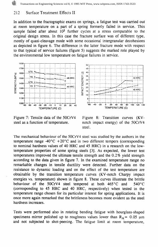
Figure 9: Macroscopic view of thefracture surface of a broken roll axle.
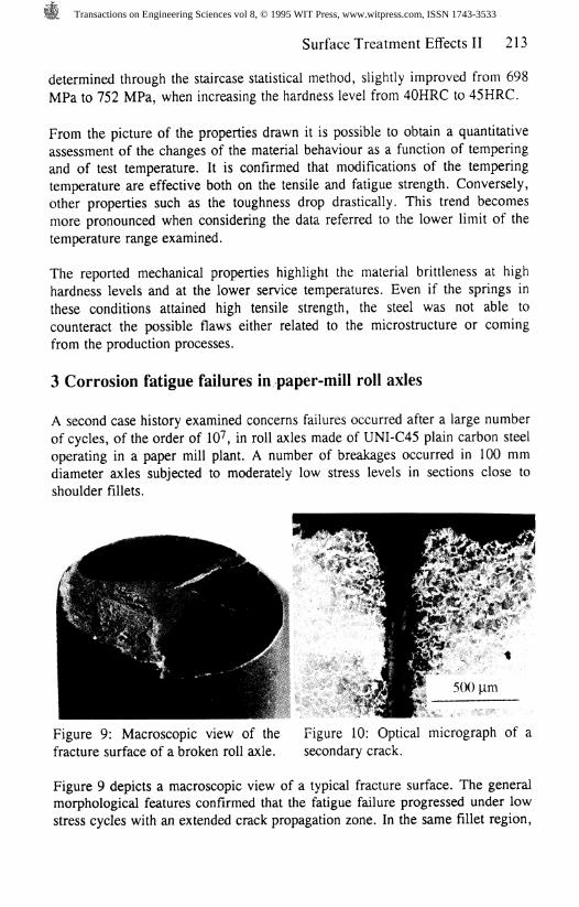
Figure 10: Optical micrograph of asecondary crack.
Figure 9 depicts a macroscopic view of a typical fracture surface. The generalmorphological features confirmed that the fatigue failure progressed under lowstress cycles with an extended crack propagation zone. In the same fillet region,
Transactions on Engineering Sciences vol 8, © 1995 WIT Press, www.witpress.com, ISSN 1743-3533
214 Surface Treatment Effects II
a 40 mm length crack was observed in another axle. Metallographic analyses,figure 10 showed that the crack was filled with corrosion products and that itsflanks we're not decarburised, thus excluding any defect brought about by the
manufacturing stage.
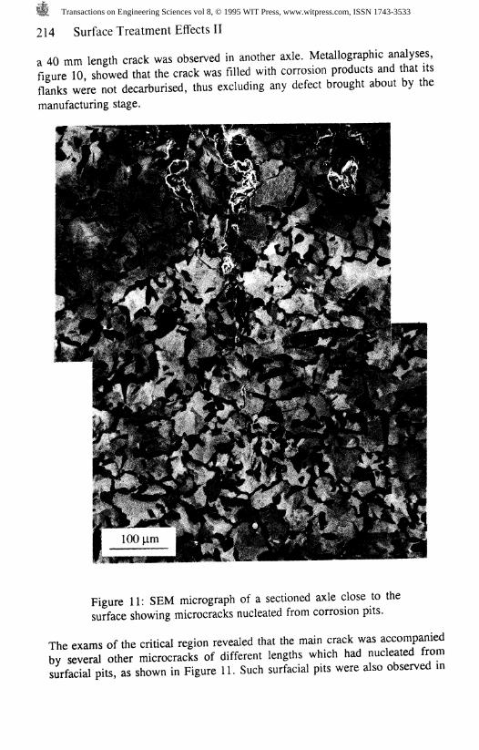
Figure 11: SEM micrograph of a sectioned axle close to thesurface showing microcracks nucleated from corrosion pits.
The exams of the critical region revealed that the main crack was accompaniedby several other microcracks of different lengths which had nucleated fromsurfacial pits, as shown in Figure 11. Such surfacial pits were also observed in
Transactions on Engineering Sciences vol 8, © 1995 WIT Press, www.witpress.com, ISSN 1743-3533
Surface Treatment Effects II 215
crack-free regions of the axles, far from the shoulder fillets. These weresupposed to be brought about by the corrosive environment in which thecomponents operated.
Figures 10 and 11 also allow to discuss about the steel microstructure, whichwas of pearlitic-ferritic type, as formed by a normalising thermal treatment (thehardness was about 200 BHN). It is well known [4-6] that such microstructuredoes not lead to particularly favourable fatigue properties due to the twoinhomogeneous constituents and to the presence of cementite lamellas thatfavours notch effects on a microscale and crack propagation.
From the above observations it was concluded that the failures were due to asequence of corrosion and fatigue mechanisms. Firstly, environmental corrosiveattack caused pits, homogeneously distributed on the whole axle surface. In theregion near the shoulder fillet, where the material was subjected to notcheffects, fatigue microcracks originated from these surfacial defects and easilypropagated through an unsuitable microstructure.
4 Concluding remarks
By examining a case of failures of helical springs used in cable transportationplants, the influence of steel tensile strength, surface condition andenvironmental temperature on fatigue behaviour of steels was discussed. Theinvestigations allowed to state that the nucleation of the fatigue cracks wasbrought about by the geometrical irregularities left by the too intensive shot-peening process. Despite its high tensile strength, the steel used, highly stressedin service, was not able to withstand the presence of defects due to poortoughness properties, thus fatigue cracks easily generated and propagated.
The low toughness of the Cr-V steel was connected to a number of useconditions of the material which must be necessarily satisfied in order to reachhigh strength levels required by modern spring design. Amongst these factorsthere can be listed the low tempering temperature chosen to obtain highhardness and YS/UTS ratios, the possibility of falling with this temperaturewithin the embrittling interval, the exercise of the spring in low-temperatureenvironments.
The investigations carried out on roll axles failed in a paper-mill plant revealedmodification of the surface finish by environmental corrosive attack bringingabout pits which acted in particularly stressed regions as nucleation sites forfatigue microcracks. Eventually, these cracks were able to grow in a steel notheat treated to the most favourable condition as far as fatigue strength isconcerned.
Transactions on Engineering Sciences vol 8, © 1995 WIT Press, www.witpress.com, ISSN 1743-3533
216 Surface Treatment Effects II
In both the examined cases the strong effect of surfacial finish on fatigueproperties was neglected or at least misconsidered at the design stage thusgiving rise to unexpected service failures. The effects of surface condition wereparticularly deleterious due to either the high brittleness of the steel or to theunsuitable microstructure.
References
1. Hurd N.J., Irwing P.E., in "Design of Fatigue and Fracture ResistantStructures", ASTM STP 761, Ed. Abelkis P.R., Hudson C.M., 1982, p.212-223.
2. Metals Handbook Ninth Edition, Vol. 11 - Failure Analisys andPrevention, ASM, 1986.
3. Gariboldi E., Nicodemi W., Silva G., Vedani M., Metall. Sci. Techn., 12,1 (1994), 11-21.
4. Buch A., Fatigue Strength Calculation, Material Science Survey N. 6,Trans Tech Publications, 1988, p. 212 - 222.
5. Francois D., Influence of Microstructure on Fatigue, in Proc. Advences inFatigue Science and Technology, ed. C.M. Branco, L. Guerra Rosa,Kluwer Academic Publisher, 1989, p. 83 - 76.
6. Fine E.M., Fatigue Resistance of Metals, Metallurgical Transactions, 11A(1980) 359 - 379.
Transactions on Engineering Sciences vol 8, © 1995 WIT Press, www.witpress.com, ISSN 1743-3533