01 - vigilaweld · 2017-09-04 · 4 el wgc1 es un preciso regulador de caudal para gases con...
TRANSCRIPT


01 Características del equipo ___________________ 4 Equipment Features
02 Parámetros que mide y datos que presenta ___________________ 5 Measuring Parameters and Displayed Data
03 Alarmas de funcionamiento ___________________ 6 Operating Alarms
04 Otras opciones ___________________ 6 Other Options
05 Instalación de gas típica ___________________ 7 Typical Gas Installation
06 Conexión eléctrica ___________________ 8 Electric Connection
07 Entradas eléctricas ___________________ 9 Electric Inputs
08 Salidas eléctricas ___________________ 10 Electrical Outputs
09 Esquemas de conexión eléctrica ___________________ 11 Electrical Wiring Diagrams
10 Operación y configuración ___________________ 13 Operation and Configuration
A1 Ficha técnica ___________________ 28 Technical Data
A2 Lista de repuestos VIGILAWELD WGC1 ___________________ 30 List of Spare Parts
A3 Tabla densidad de gases ___________________ 32 Welding gases density
Pantalla GasGas Screen
Pantalla Ajuste-Presión ResidualSetting-Residual Pressure Screen
Pantalla JOBJOB Screen
Pantalla Alarmas programables (Sólo en modo regulador)Programmable Alarm Screen (Only in Regulator Mode)
Ajuste de la alarma de presión de entrada mínimaAdjustement of the Minimum Input Pressure Alarm
Ajuste de la alarma de presión de salida máximaAdjustement of the Maximum Output Pressure Alarm
Alarma de fugas en ciclo de Posflujo - EsperaAlarm of Leakage in Posflow Cycle - Waiting
Funcionamiento de las AlarmasAlarm Operation
Pantallas de visualización de alarmasAlarm Display Screens
Pantalla de Eventos (Extra opcional)Event Screen (Optional feature)
Pantalla MenúMenu Screen
Pantalla ModoMode Screen
Operación del aparatoDevice operationInicio de operaciónStart of OperationPantalla de trabajo principalMain Work Screen
Pantalla de trabajo secundariaSecondary Work Screen

www.vigilaweld.com4
El WGC1 es un preciso regulador de caudal para gases con densidades comprendidas entre 1.000 y 2.000 g/m3 y especialmente concebido para trabajar en celdas robotizadas e instalaciones semiautomáticas o automáticas de soldadura MIG o TIG. Aporta una serie de ventajas totalmente novedosas en el control de gases utilizados en los procesos de soldadura:
WGC1 is a precise flow regulator for gases with densities between 1,000 and 2,000 g/m3, specially designed to work with robotic cells and semi-automatic or automatic MIG or TIG welding installations. It offers several new advantages in the control of gases used in the welding processes:
• visualización precisa del caudal y las presiones reales flow rate and actual pressure accurate visualization
• control externo del caudal external flow control
• regulación de un caudal independiente en el postflujo independent flow and post flow regulation
• posibilidad de registro del caudal de cada cordón flow record possibility
• cálculo del consumo, saber si hay problemas en la instalación, etc. consumption calculation, installation problems detection, etc.
Estas son cuestiones que quedan totalmente resueltas con el WGC1 que reúne más de diez funciones eminentemente prácticas y útiles para el usuario en un único equipo. Se ha diseñado para integrarse muy facilmente bajo el control y supervisión del robot de soldadura o bien de forma aislada del mismo, siendo la primera opción la recomendable para aprovechar toda las funcionalidades que posee.
These are issues that are totally resolved with WGC1 that brings more than ten eminently practical and useful functions for the user in one. It has been designed to be easily integrated under the control and supervision of the welding robot or in isolation from it. Being the first option the recommended to benefit of all the functionalities that is possesses.
01 Características del equipo Equipment Features

DOC: M2017-08-01/V05
• Presión de entrada con precisión de décimas de bar Inlet pressure with precision of tenths of bar
• Presión de salida con precisón de décimas de bar Out pressure with precision of tenths of bar
• Caudal real con décimas de l/min Actual flow rate with tenths of l/min
• Caudal consignado flujo/posflujo Flow/post-flow rate
• Totalizador de litros consumidos hasta 5.000.000 Liters consumed totalizer of up to 5,000,000
• Totalizador de cordones realizados hasta 5.000.000 Seams totalizer up to 5,000,000
• Ciclo de trabajo: ESPERA-SOLDADURA-POSFLUJO Working cycle: WAIT-WELDING-POSFLOW
• JOB de gas en uso Gas JOB in use
• Gas de trabajo seleccionado Type of Gas selected
02 Parámetros que mide y datos que presenta Measuring Parameters and Displayed Data
La primera de las razones para recomendar este equipo es el ahorro de gas de hasta un 40% sobre una instalación convencional y que podemos medir sencillamente. Pero la verdadera utilidad es poder controlar continuamente que el gas aplicado sea el correcto, puesto que nos avisa de situaciones anormales de trabajo y el robot puede tener constancia de que el gas aplicado sea realmente el que hemos seleccionado.
The first reason to recommend this equipment is the gas savings, of up to 40% on a conventional installation and that we can measure easily. But the true utility is that we can continuously control that the applied gas is correct, since it warns us of abnormal work situations and the robot can have evidence that the gas applied is really the one we have selected.
www.vigilaweld.com6
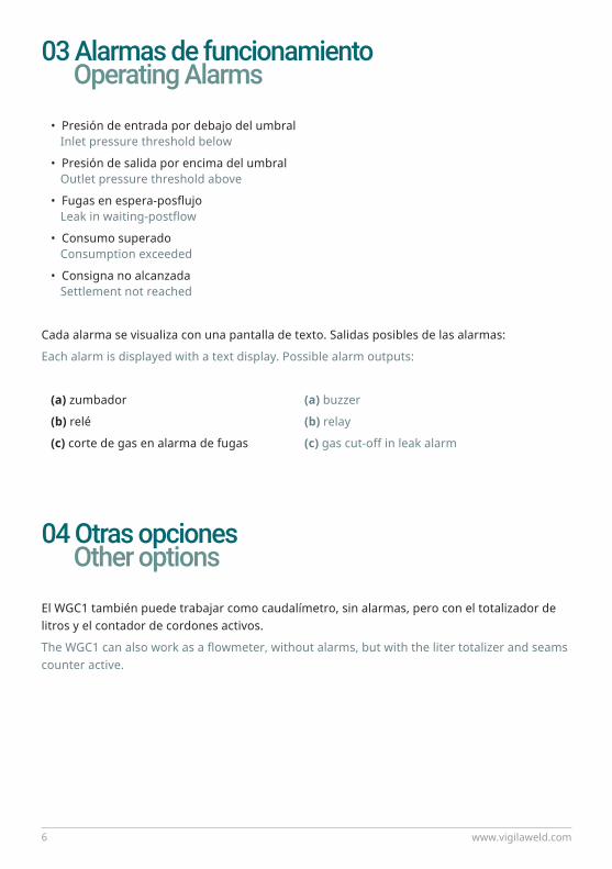
El WGC1 también puede trabajar como caudalímetro, sin alarmas, pero con el totalizador de litros y el contador de cordones activos.
The WGC1 can also work as a flowmeter, without alarms, but with the liter totalizer and seams counter active.
• Presión de entrada por debajo del umbral Inlet pressure threshold below
• Presión de salida por encima del umbral Outlet pressure threshold above
• Fugas en espera-posflujo Leak in waiting-postflow
• Consumo superado Consumption exceeded
• Consigna no alcanzada Settlement not reached
Cada alarma se visualiza con una pantalla de texto. Salidas posibles de las alarmas:
Each alarm is displayed with a text display. Possible alarm outputs:
(a) zumbador (a) buzzer
(b) relé (b) relay
(c) corte de gas en alarma de fugas (c) gas cut-off in leak alarm
03 Alarmas de funcionamiento Operating Alarms
04 Otras opciones Other options

DOC: M2017-08-01/V07
Se debe instalar prioritariamente directamente a la red de gas hasta 6 bares de presión, más presión bajo demanda. Se pueden mantener momentáneamente para pruebas los sistemas mecanicos de regulación, SIEMPRE QUE SE ABRA EL PASO AL MÁXIMO.
MUST be installed PRIORITALLY directly to the gas network up to 6 bar pressure, more pressure on demand. However, mechanical flow control systems can be kept temporarily for testing, ONLY IF THE GAS PASSAGE IS TOTALLY OPENED.
! IMPORTANTE: Por cada 10l/min de caudal se necesita mínimo 1bar de diferencia de presión entre la entrada y la salida del equipo.
! IMPORTANT: for every 10 l/min of flow, a minimum of 1 bar of pressure difference between the inlet and outlet of the equipment is required.
05 Instalación de gas típica Typical Gas Installation

www.vigilaweld.com8
06 Conexión eléctrica Electric Connection
CABLEADO CONECTOR DB 15:
CONNECTOR DB 15 WIRING:
1. entrada digital nº1 LIBRE GND. chasis y masa digital input nº1 FREE chasis & ground
2. entrada digital nº2 SOLDADURA (arc on) 15. N.O. relé digital input nº2 WELDING (arc on) N.O. relé
3. entrada digital nº3 14. N.C. relé digital input nº3 N.C. relé
4. entrada digital nº4 13. COMÚN relé digital input nº4 COM relé
5. entrada digital nº5 12. negativo y masa digital input nº5 negative & ground
6. entrada analógica 11. +24v entrada alimentación aparato analog input +24v input supply
7. salida analógica 10. +5v salida analog output +5v output
8. negativo y masa 9. común entradas digitales negative & ground (aisladas galvánicamente) common digital inputs (galvanic isolated)
El negativo/masa también lo es de la entrada y salida analógica. El regulador posee una entrada independiente de alimentación de 24 voltios en caso de no alimentarlo con la tensión auxiliar del robot a través del conector db15.
The negative/ground is also of the analog input and output. The regulator has an independent 24-volt power input in case of not using the auxiliary 24vcc of the robot through the db15 connector.

DOC: M2017-08-01/V09
07 Entradas eléctricas Electric Inputs
Estas entradas pueden ser comandadas por el robot, de forma análoga a como se comanda una fuente de potencia de soldadura. Prima la sencillez y se hace por medio de entradas discretas cableadas.
These inputs can be controlled by the robot, in the same way as a soldering power source is commanded. Simplicity is emphasized and it is done by discrete wired inputs.
Entrada de Consigna analógica (db15 - 6) de gas entre 0,0 y 3,0V donde 1,0V son 10l/min
Analog setpoint input (db15 - 6) between 0.0 and 3.0V where 1.0V is 10l/min
Entrada de Consigna digital, con combinaciones de tres entradas (db15 - d3,d4,d5) podemos habilitar siete Consignas de Caudal de gas o JOBS de gas, con un flujo/posflujo independiente para cada JOB
Digital setpoint input, with combinations of three inputs (db15 - d3, d4, d5) we can enable seven Flow Setpoints of Gas or Gas JOBS, with an independent flow / post flow for each JOB
d3 d4 d5 (entradas digitales) (digital inputs) 0 - 0 - 0 habilita la consigna analógica enables the analog setpoint 0 - 0 - 1 habilita JOB1 enables JOB1 0 - 1 - 0 habilita JOB2 enables JOB2 0 - 1 - 1 habilita JOB3 enables JOB3 1 - 0 - 0 habilita JOB4 enables JOB4 1 - 0 - 1 habilita JOB5 enables JOB5 1 - 1 - 0 habilita JOB6 enables JOB6
1 - 1 - 1 habilita JOB7 enables JOB7
El JOB se puede cambiar sobre la marcha dentro de un mismo cordón de soldadura. (0 es circuito abierto, 1 es activado con tensión positiva conectada, aisladas galvánicamente, pueden alimentarse con tensiones comprendidas entre +5 y +24 voltios c.c.
The JOB can be changed on the fly within the same welding seam. (0 is open circuit, 1 is activated with positive voltage connected) , galvanically isolates, which can be supplied with voltages between +5 and +24 volts a.c.

www.vigilaweld.com10
08 Salidas eléctricas Electrical Outputs
En la entrada digital (db15 - d2) podemos conectar la señal de ARC-ON del robot, estación automática o pulsador de antorcha, aunque también se puede conectar un interruptor detector de corriente que se suministra separadamente.
At the digital input (db15 - d2), we can connect the AR-CON signal of the robot, automatic station or torch button, but also a current detector switch that is supplied can be connected.
Tenemos otra entrada digital LIBRE (db15 - d1) para usos futuros.
We have another FREE digital input (db15 - d1) for future uses.
En caso que no haya en uso ninguna entrada digital tendremos activada la entrada analógica (1 voltio son 10,0 l/min) la consigna la veremos reflejada en la pantalla secundaria.
If no digital input are used, the analogue input will be activated (1 volt is 10.0 l/min) And the setpoint will be reflected in the secondary display.
Salida analógica (db15 - 7) donde cada 10l/min de gas real son 1,0 V
Analog output (db15 - 7) where every 10l/min of actual gas is 1.0V
Esta salida es importante ya que con ella el robot puede constatar CORDÓN POR CORDÓN el gas real con que se está soldando una pieza y llevar control de trazabilidad para el cliente.
This output is relevant as it allows the robot to verify SEAM BY SEAM the actual gas with which a part is being welded and carry traceability control for the customer.
Salida de 5v (db15 - 10) para alimentación de entradas digitales o analógica
5v output (db15 - 10) for digital or analog input power
Salida de relé para alarmas (db15 - 13,14,15) con un contacto conmutado libre de potencial
Relay output for alarms (db15 - 13,14,15) with a potential-free switched contact

DOC: M2017-08-01/V011
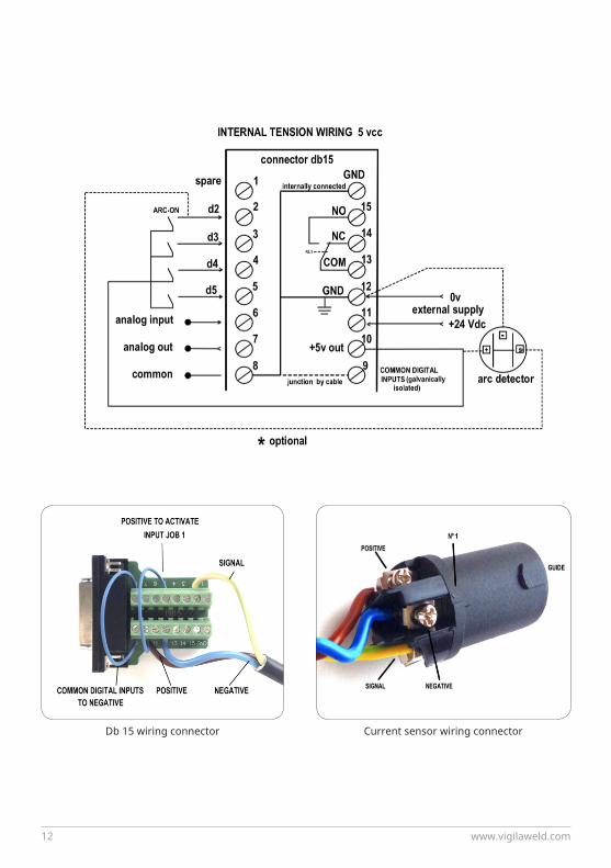
09 Esquemas de conexión eléctrica Electrical Wiring Diagrams
Posicionamiento del detector de corriente sobre el cable de potencia con una brida. (negativo o positivo indistintamente)Current sensor mounted over the power solder cable with an adjus-table strap. (negative or positive cable indistinctly)
www.vigilaweld.com12
Db 15 wiring connector Current sensor wiring connector

DOC: M2017-08-01/V013
10 Operación y configuración Operation and Configuration
Operación del aparatoDevice operation
Inicio de operaciónStart of Operation
La tecla MENU nos lleva al menu general o al anterior.
La tecla SALIR nos lleva a la pantalla de trabajo PRINCIPAL.
La tecla OK siempre nos introduce en una opción seleccionada de MENÚ.
La tecla SEL -selección- pasa por todas las opciones que se pueden elegir o modificar.
Las teclas < > sirven para pasar de la pantalla de trabajo PRINCIPAL a la SECUNDARIA.
Las teclas - + sirven para aumentar o disminuir las cifras ajustables.
- LOS CAMBIOS SE VALIDAN AUTOMÁTICAMENTE.
The MENU key go to the general menu or to the previous menu.
The OUT key go to the MAIN work screen.
The OK key always enter in a selected option of MENU.
The SEL key - selection - goes through all the options that can be chosen or modified.
The <> keys are used to move from the MAIN work screen to the SECONDARY.
The - + keys are used to increase or decrease the adjustable digits.
- CHANGES VALIDATE AUTOMATICALLY.
En la pantalla de arranque aparece la versión de software del equipo y el número de referencia. Posteriormente pasa a la pantalla de trabajo principal. Puede empezar a trabajar como regulador o como caudalímetro, dependiendo de lo que hayamos seleccionado antes de apagarlo.
The computer software version and the reference number are displayed on the startup screen. Then go to the main working screen. It can start working as a regulator or as a flowmeter, whatever was selected before turning it off.

www.vigilaweld.com14
Pantalla de trabajo principalMain Work Screen
En la primera linea aparece el ciclo de trabajo: ESPERA - SOLDADURA - POSFLUJO
In the first line the work cycle appears: WAIT - WELDING - POSFLOW
En la segunda línea aparecen la presión de entrada y de salida entre 0,0 y 8,0 bares, valores superiores no son visualizados. La presión de entrada corresponde a la de la instalación del gas y puede estar comprendida entre 2,5 y 6 bares. Según el caudal de trabajo necesitaremos una presión mínima.
The second line shows the inlet and outlet pressure between 0.0 and 8,0 bar, higher values are not displayed. The inlet pressure corresponds to that of the gas installation and can be between 2,5 and 6 bar. Depending on the flow rate, we need a minimum pressure.
En la tercera línea aparece el caudal real instantáneo. Cualquiera de las dos flechas accede a la pantalla secundaria y viceversa. En la cuarta línea aparecen las funciones de las teclas que hay contiguas debajo.
The third line shows the actual flow. Either of the two arrows accesses the secondary screen and vice versa. The fourth line shows the functions of the keys next to them.

DOC: M2017-08-01/V015
Pantalla de trabajo secundariaSecondary Work Screen
La pantalla secundaria tiene datos complementarios, aparece pulsando cualquiera de las teclas -O- en la página principal, pulsando de nuevo volvemos a la principal.
The secondary screen has complementary data, appears by pressing any of the <OR> keys on the main page, pressing again we go back to the main.
En la primera linea tenemos el gas seleccionado: Ar - O2 - Aire - N - Co2 - Ajustable. Luego tenemos el JOB activo, y a su derecha el caudal en l/m consignados.
In the first line is displayed the selected gas: Ar - O2 - Air - N - Co2 - Adjustable. Then we have the active JOB, and to the right, the setpoint flow in l/min.
Con el botón de RESET borramos las cifras de los totalizadores de litros y cordones, pero las cifras almacenadas no se borran al apagar o cambiar de modo de trabajo, la cifra máxima en ambos contadores es de 5.000.000.
With the RESET button we delete the numbers of liters and seams totalized, but the stored figures are not deleted when switching off or changing working mode, the maximum number in both counters is 5,000,000.

www.vigilaweld.com16
Pantalla MenúMenu Screen
En la pantalla secundaria, pulsando la tecla derecha por más de 5 segundos aparece encima la palabra y la opción de acceso al MENÚ, al apagar el aparato desaparece la opción de MENÚ. Pulsando la tecla de MENÚ aparecen las siguientes opciones:
On the secondary screen, by pressing the right button for more than 5 seconds, the word MENU appear on the screen. When the device is turned off, the MENU option disappears. Press the MENU key to display the following options:
La tecla SEL sirve para elegir la opción del menú en la que queremos entrar.
The SEL key is used to choose the menu option in which we want to enter.
Las dos teclas centrales -SALIR- sirven para volver directamente a la pantalla de trabajo principal.
The two center keys -OUT- serves to return directly to the main screen.
La tecla OK sirve para entrar en la opción elegida del menú .
The OK key is used to enter to the chosen menu option.
DOC: M2017-08-01/V017
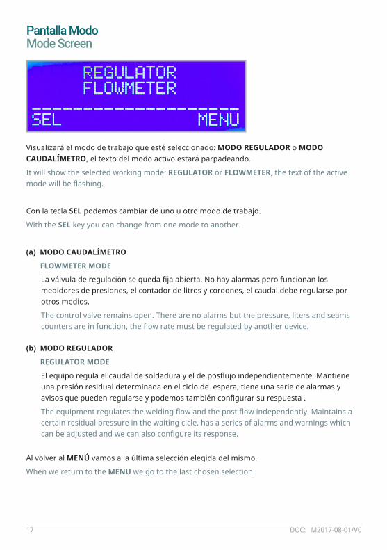
Pantalla ModoMode Screen
Visualizará el modo de trabajo que esté seleccionado: MODO REGULADOR o MODO CAUDALÍMETRO, el texto del modo activo estará parpadeando.
It will show the selected working mode: REGULATOR or FLOWMETER, the text of the active mode will be flashing.
Con la tecla SEL podemos cambiar de uno u otro modo de trabajo.
With the SEL key you can change from one mode to another.
(a) MODO CAUDALÍMETRO
FLOWMETER MODE
(b) MODO REGULADOR
REGULATOR MODE
Al volver al MENÚ vamos a la última selección elegida del mismo.
When we return to the MENU we go to the last chosen selection.
La válvula de regulación se queda fija abierta. No hay alarmas pero funcionan los medidores de presiones, el contador de litros y cordones, el caudal debe regularse por otros medios.
The control valve remains open. There are no alarms but the pressure, liters and seams counters are in function, the flow rate must be regulated by another device.
El equipo regula el caudal de soldadura y el de posflujo independientemente. Mantiene una presión residual determinada en el ciclo de espera, tiene una serie de alarmas y avisos que pueden regularse y podemos también configurar su respuesta .
The equipment regulates the welding flow and the post flow independently. Maintains a certain residual pressure in the waiting cicle, has a series of alarms and warnings which can be adjusted and we can also configure its response.

www.vigilaweld.com18
Pantalla GasGas Screen
Pantalla JOBJOB Screen
Aparece la lectura GAS SELECTION, y debajo el gas que está actualmente seleccionado, así como su densidad en g/m3, a 20ºC, esta segunda línea varía cada vez que pulsamos el botón izquierdo SEL, apareciendo consecutivamente el nombre de todos los gases disponibles y su densidad.
The display reads GAS SELECTION, and below the currently selected gas as well as its density in g/m3, at 20ºC, this second line varies every time we press the left SEL button, appearing consecutively the name of all available gases and their density.
Aquí podemos ajustar el caudal de flujo y posflujo de cada JOB de los siete disponibles.
Después del ultimo gas aparece una densidad ajustable para mezcla de gases. Ajustaremos la densidad, a 20ºC, entre 1000 y 2000 g/m3 de 10 en 10 g/m3.
After the last gas appears an adjustable density for gas mixture. We will adjust the density, at 20ºC, between 1000 and 2000 g/m3 of 10 in g/m3.

DOC: M2017-08-01/V019
Pantalla Ajuste-Presión ResidualSetting-Residual Pressure Screen
El aparato memoriza la presión en ciclo de soldadura, y la mantiene en el ciclo de ESPERA con la tubería cerrada, a esta presión le llamamos RESIDUAL, con este ajuste podemos incrementarla desde 0,0 hasta 1,0 bar por encima de la memorizada en soldadura.
The device memorizes the pressure in the welding cycle, and keeps it in the WAIT cycle with the pipe closed, at this pressure we call RESIDUAL, with this setting we can increase it from 0.0 to 1.0 bar above the one stored in welding.
Cuando cesa la soldadura empieza el ciclo de POSFLUJO, si la presión de salida supera la PRESIÓN RESIDUAL fijada, cierra la válvula de regulación, manteniendo dicha presión pasando a ciclo de ESPERA, (esto sucede cuando cierra la válvula de la devanadora). Si la tubería pierde presión pueden producirse aperturas de válvula para compensar la pérdida de presión. Esas pérdidas las podemos vigilar, como luego explicamos.
When the soldering stops, the POSFLOW cycle starts. If the output pressure exceeds the set RESIDUAL PRESSURE, it closes the regulating valve, keeping the pressure in the WAIT cicle (this happens when closing the valve of the wire winder). If the pipe loses pressure, valve openings may occur to compensate for pressure loss. We can monitor these losses, as explained later.
Parpadea el nombre de la variable a cambiar. Con la tecla SEL pasamos consecutivamente por los ajustes de JOB - FLUJO - POSFLUJO - JOB, etc. en función rotativa. El ajuste de flujo y posflujo es independiente y se modifica a la décima.
NOTA: El ajuste de flujo y posflujo está limitado entre 5 y 25 l/min.
Here we can adjust the flow and post flow of each JOB of the seven available. The name of the variable to be changed flashes. With the SEL key, we go consecutively through the settings of JOB - FLOW - POSFLOW - JOB, etc. in rotary function. The flow and post flow adjustment is independent and they can be adjusted to the tenth.
NOTE: Flow and post flow adjustment is limited between 5 and 25 l/min.

www.vigilaweld.com20
Pantalla Alarmas programables (Sólo en modo regulador)Programmable Alarm Screen (Only in Regulator Mode)
Ajuste de la alarma de presión de entrada mínimaAdjustement of the Minimum Input Pressure Alarm
En esta pantalla seleccionamos el umbral de disparo de las alarmas de;
In this screen we select the trip threshold of the alarms of;
• presión de entrada mínima • presión de salida máxima en ciclo de soldadura
minimum input pressure maximum output pressure in welding cycle
• consumo de gas superado • litros de fuga máximos en ciclo de espera
gas consumption exceeded maximum leakage liters in waiting cycle
Con la tecla SEL, de forma análoga como hacíamos en el menú principal, seleccionamos en función rotativa la alarma a ajustar. Con OK entramos en la pantalla de configuración de la misma.
With the SEL key, in the same way as in the main menu, select the alarm to be set in rotary mode. Press OK to enter the configuration screen.
Seleccionamos la presión mínima entre 0,0 y 6,0 bares, si la presión baja de la ajustada nos dará una pantalla de alarma. Si seleccionamos 0 la alarma queda desactivada.
We select the minimum pressure between 0.0 and 6.0 bar, if the pressure descends from the set one, it will give us an alarm screen. If you select 0, the alarm is disabled.

DOC: M2017-08-01/V021
Ajuste de la alarma de presión de salida máximaAdjustement of the Maximum Output Pressure Alarm
Es una alarma para controlar la presión en el ciclo de SOLDADURA, el rango es entre 0,0 y 2,0 bares, esta alarma controla los posibles atascos en la instalación. Si seleccionamos 0 la alarma queda desactivada.
This is an alarm to control the pressure in the WELD cycle, the range is between 0.0 and 2.0 bar, this alarm controls possible jams in the installation. If we select 0 the alarm is disabled.
Seleccionamos con SEL, por medio del texto parpadeante, la cifra que queremos cambiar o las opciones complementarias a activar cuando haya alarma. El equipo es capaz de mantener el caudal consignado aunque suba la presión de salida hasta 1,5 bares, siempre que la presión de entrada sea suficiente.
IMPORTANTE: Por cada 10 l/min de caudal necesitamos como minimo 1 bar de diferencia entre la presión de entrada y la de salida. Ejemplo: Un caudal de 15l/min con 1 bar de salida necesita 2,5 bares de entrada mínimo.
LA PRESION DE SALIDA NORMAL EN UNA ANTORCHA ROBOT OSCILA ENTE 0,4 Y 0,7 BARES, MAS PRESIÓN EN CICLO DE SOLDADURA ES SÍNTOMA DE MALA CIRCULACIÓN DE GAS.
With SEL, select that we want to change or the complementary options . The equipment is capable of maintaining the set flow rate while the input pressure is sufficient
IMPORTANT: For every 10 l/min of flow, we need at least 1 bar of difference between inlet and outlet pressure. Example: A flow of 15l/min with 1 bar output requires 2.5 bar of minimum input.
THE NORMAL OUTPUT PRESSURE ON A ROBOT TORCH VARIES FROM TO 0.4 AND 0.7 BARS, MORE PRESSURE IN WELDING CYCLE IS A SYMPTOM OF BAD GAS CIRCULATION.
Elegimos con SEL la cifra que queremos cambiar y la opción complementaria a activar, que puede ser activación de un zumbador o de un relé (la opción elegida estará parpadeando). Más adelante veremos el comportamiento de estas opciones de salida.
With SEL we can change the options to activate, which can be activation of a buzzer or a relay (the chosen option will be flashing). Later we will see the behavior of these output options.
www.vigilaweld.com22
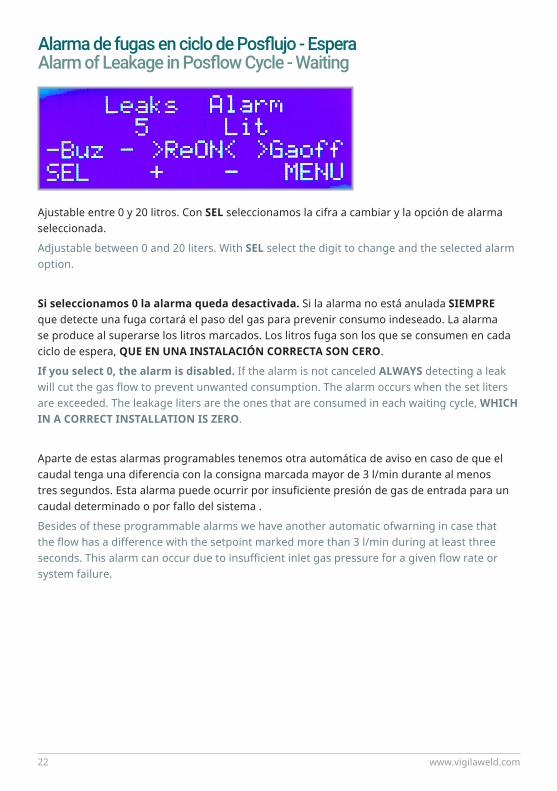
Alarma de fugas en ciclo de Posflujo - EsperaAlarm of Leakage in Posflow Cycle - Waiting
Ajustable entre 0 y 20 litros. Con SEL seleccionamos la cifra a cambiar y la opción de alarma seleccionada.
Adjustable between 0 and 20 liters. With SEL select the digit to change and the selected alarm option.
Si seleccionamos 0 la alarma queda desactivada. Si la alarma no está anulada SIEMPRE que detecte una fuga cortará el paso del gas para prevenir consumo indeseado. La alarma se produce al superarse los litros marcados. Los litros fuga son los que se consumen en cada ciclo de espera, QUE EN UNA INSTALACIÓN CORRECTA SON CERO.
If you select 0, the alarm is disabled. If the alarm is not canceled ALWAYS detecting a leak will cut the gas flow to prevent unwanted consumption. The alarm occurs when the set liters are exceeded. The leakage liters are the ones that are consumed in each waiting cycle, WHICH IN A CORRECT INSTALLATION IS ZERO.
Aparte de estas alarmas programables tenemos otra automática de aviso en caso de que el caudal tenga una diferencia con la consigna marcada mayor de 3 l/min durante al menos tres segundos. Esta alarma puede ocurrir por insuficiente presión de gas de entrada para un caudal determinado o por fallo del sistema .
Besides of these programmable alarms we have another automatic ofwarning in case that the flow has a difference with the setpoint marked more than 3 l/min during at least three seconds. This alarm can occur due to insufficient inlet gas pressure for a given flow rate or system failure.
DOC: M2017-08-01/V023
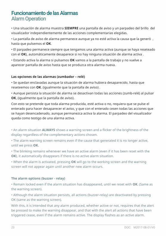
Funcionamiento de las AlarmasAlarm Operation• Una situación de alarma muestra SIEMPRE una pantalla de aviso y un parpadeo del brillo del visualizador independientemente de las acciones complementarias elegidas.
• La pantalla de aviso de alarma permanece aunque ya no esté activa la causa que la generó , hasta que pulsemos el OK.
• El parpadeo permanece siempre que tengamos una alarma activa (aunque se haya reseteado con el OK), automáticamente desaparece si no hay ninguna situación de alarma activa .
• Estando activa la alarma si pulsamos OK vamos a la pantalla de trabajo y no vuelve a aparecer pantalla de aviso hasta que se produzca otra alarma nueva.
Las opciones de las alarmas (zumbador – relé)
• Se quedan enclavadas aunque la situación de alarma hubiera desaparecido, hasta que reseteemos con OK. (igualmente que la pantalla de aviso) .
• Aunque persista la situación de alarma se desactivan todas las acciones (zumb-relé) al pulsar OK, (igualmente que la pantalla de aviso).
Con esto se pretende que toda alarma producida, esté activa o no, requiera que se pulse el enterado para hacer desaparecer el aviso, y que con el enterado cesen todas las acciones que se hayan desencadenado, aunque permanezca activa la alarma. El parpadeo del visualizador queda como testigo de una alarma activa.
• An alarm situation ALWAYS shows a warning screen and a flicker of the brightness of the display regardless of the complementary actions chosen.
• The alarm warning screen remains even if the cause that generated it is no longer active, until we press OK.
• The blinking remains whenever we have an active alarm (even if it has been reset with the OK), it automatically disappears if there is no active alarm situation.
• When the alarm is activated, pressing OK will go to the working screen and the warning screen will not appear again until another new alarm occurs.
The alarm options (buzzer - relay)
• Remain locked even if the alarm situation has disappeared, until we reset with OK. (Same as the warning screen).
• Although the alarm situation persists, all actions (buzzer-relay) are deactivated by pressing OK (same as the warning screen).
With this, it is intended that any alarm produced, whether active or not, requires that the alert be pressed to make the warning disappear, and that with the alert all actions that have been triggered cease, even if the alarm remains active. The display flashes as an active alarm.
www.vigilaweld.com24
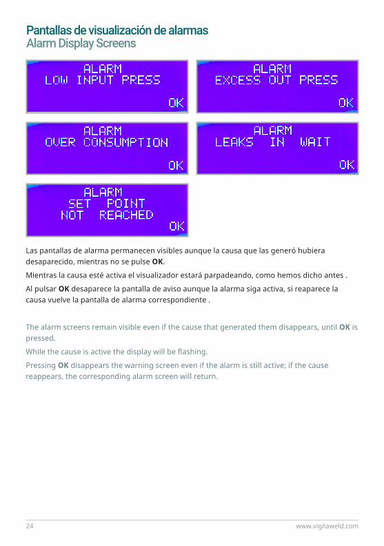
Pantallas de visualización de alarmasAlarm Display Screens
Las pantallas de alarma permanecen visibles aunque la causa que las generó hubiera desaparecido, mientras no se pulse OK.
Mientras la causa esté activa el visualizador estará parpadeando, como hemos dicho antes .
Al pulsar OK desaparece la pantalla de aviso aunque la alarma siga activa, si reaparece la causa vuelve la pantalla de alarma correspondiente .
The alarm screens remain visible even if the cause that generated them disappears, until OK is pressed.
While the cause is active the display will be flashing.
Pressing OK disappears the warning screen even if the alarm is still active; if the cause reappears, the corresponding alarm screen will return.
www.vigilaweld.com28
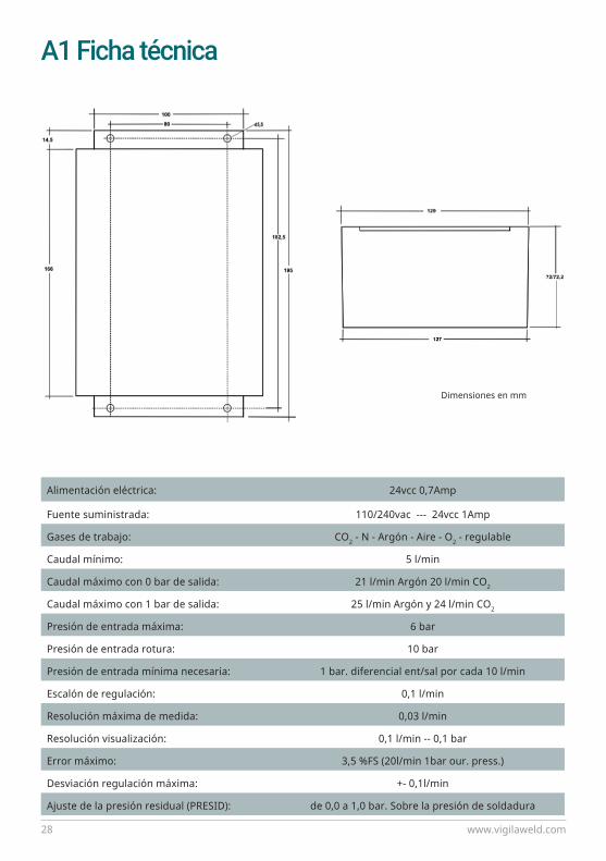
A1 Ficha técnica
Alimentación eléctrica: 24vcc 0,7Amp
Fuente suministrada: 110/240vac --- 24vcc 1Amp
Gases de trabajo: CO2 - N - Argón - Aire - O2 - regulable
Caudal mínimo: 5 l/min
Caudal máximo con 0 bar de salida: 21 l/min Argón 20 l/min CO2
Caudal máximo con 1 bar de salida: 25 l/min Argón y 24 l/min CO2
Presión de entrada máxima: 6 bar
Presión de entrada rotura: 10 bar
Presión de entrada mínima necesaria: 1 bar. diferencial ent/sal por cada 10 l/min
Escalón de regulación: 0,1 l/min
Resolución máxima de medida: 0,03 l/min
Resolución visualización: 0,1 l/min -- 0,1 bar
Error máximo: 3,5 %FS (20l/min 1bar our. press.)
Desviación regulación máxima: +- 0,1l/min
Ajuste de la presión residual (PRESID): de 0,0 a 1,0 bar. Sobre la presión de soldadura
Dimensiones en mm

DOC: M2017-08-01/V029
A1 Technical Data
Electrical power supply 24vcc 0,7Amp
Power supply provided: 110/240vac --- 24vcc 1Amp
Working gases: CO2 - N - Argón - Air - O2 - adjustable
Minimum flow: 5 l/min
Max flow rate with 0 bar output: 21 l/min Argón 20 l/min CO2
Max flow rate with 1 bar output: 25 l/min Argón and 24 l/min CO2
Maximum input pressure: 6 bar
Break input pressure: 10 bar
Minimum input pressure required: 1 bar. differential in/out for every 10 l/min
Regulating step: 0,1 l/min
Maximum measurement resolution: 0,03 l/min
Display resolution: 0,1 l/min -- 0,1 bar
Max error: 3,5 %FS (20l/min 1bar our. press.)
Maximum control deviation: +- 0,1l/min
Residual pressure adjustement (PRESID): from 0,0 to 1,0 bar. Over welding pressure
Measures in mm

www.vigilaweld.com30
A2 Lista de repuestos VIGILAWELD WGC1 List of Spare Parts
Kit WGC1 VIGILAWELDKit WGC1 VIGILAWELD
Controlador WGC1WGC1 Controlator
F. Alimentación 110-230vac -24vcc- 1Amp BNC110-230vac -24vcc- 1Amp Power Supply
Conector db15 hembra conexión tornillosConnector db15 female screws connection
Detector de corriente de arcoArc current detector
DENOMINACIÓNDENOMINATION
PVP NETOPRICE NET
389.00.500
389.20.500
389.20.024
389.20.015
389.20.005
REFITEM
Kit compuesto por:The kit consist of:

DOC: M2017-08-01/V031
Conector speakon 4 vías macho para detectorConnector speakon 4 way male for detector
Conjunto de racores 1/4” G y abrazaderas1/4” G fittings and clamps
Filtro malla latón con juntas 3/8Filter mesh brass with gaskets 3/8
Manguera apantallada 3x0,5 + pe, para detector(5m, se sirve cualquier longitud bajo demanda)Shielded hose 3x0,5 + pe, for detector(5m, any length on demand is served)
DENOMINACIÓNDENOMINATION
PVP NETOPRICE NET
389.20.004
389.20.014
389.20.038
389.20.035
REFITEM

www.vigilaweld.com32
A3 Tabla densidad de gases Welding gases density
puregases ºC CO2 Ar O2 Aire N2 HeSTP 0,0 1977 1780 1429 1293 1250 178
10,0 1923 1732 1390 1258 1216 17315,0 1896 1709 1370 1240 1199 17120,0 1869 1685 1351 1223 1182 168
NTP 25,0 1842 1661 1331 1205 1165 1665,40 4,76 3,92 3,52 3,40 0,48366 374 365 367 368 371
ref.MESSER CO2 Ar O2 Aire N2 He H2 25ºC 20ºC 10ºC 0ºCratiomix. % % % % % % % NTP STP
AluHe15N 84,99 0,015 15 1437 1457 1498 1540AluHe30 70 30 1213 1230 1265 1299AluHe50 50 50 914 927 953 979AluHe50N 49,99 0,015 50 913 927 953 979AluHe70 30 70 615 623 641 659AluN/N3 99,99 0,015 1661 1685 1732 1780FeC5X5/C3X1 5,0 90 5 1654 1677 1725 1772FeC6X1 6,0 93 1 1669 1693 1740 1788FeC8 8,0 92 1675 1700 1748 1796FeC18 18,0 82 1694 1718 1767 1815FeC12X2 12,0 86 2 1676 1700 1748 1797FeC15X5 15,0 80 5 1672 1696 1744 1792FeC20 20,0 80 1697 1722 1771 1819FeX4 96 4 1648 1671 1719 1766FeX8 92 8 1635 1658 1705 1752raizH5 95 5 1107 1123 1155 1188raizH10-H20 90 10 1049 1064 1094 1125inoxC2 2,5 97 1657 1681 1729 1776inoxC3X1 3,0 96 1 1663 1687 1735 1782inoxH2/H3 98 2 1628 1651 1698 1744inoxHe3H-H1 96 3,2 0,8 1600 1623 1669 1714inoxHe15C2 2,5 83,00 15 1450 1470 1512 1554inoxN1 98,75 1,250 1655 1679 1726 1773inoxN2 2,5 97,50 2,500 1695 1719 1768 1816inoxX1/X2 98,00 2 1654 1678 1726 1773LaserLe6.20 4,5 13,80 82 380 385 396 407
<incr.g/m3porcadaºC<relacionincremental
WELDINGGASESDENSITY
g/m3

