05 skyedge ii inbound overview v6.1
TRANSCRIPT

8/12/2019 05 SkyEdge II Inbound Overview v6.1
http://slidepdf.com/reader/full/05-skyedge-ii-inbound-overview-v61 1/44
SkyEdgeI I
Inbound Overview

8/12/2019 05 SkyEdge II Inbound Overview v6.1
http://slidepdf.com/reader/full/05-skyedge-ii-inbound-overview-v61 2/44
2
Agenda
IB Carrier Introduction
Configuration Parameters
Carrier Types
Time Frequency Plan (TFP)
DVB-RCS BenefitsSlot Types
Capacity Requests
ICM IB Adaptivity

8/12/2019 05 SkyEdge II Inbound Overview v6.1
http://slidepdf.com/reader/full/05-skyedge-ii-inbound-overview-v61 3/44
3
InboundDVB-RCS Introduction
SkyEdge II Inbound Channel is based in DVB-RCS (EN 301 790)
Access Scheme based on dynamic MF-TDMA Multi-Frequency Time-DivisionMultiple Access
The DVB-RCS standard defines Physical and Media Access Control (MAC)levels of the satellite segment (OSI layers 1 and 2).
Modulation and Coding
Access Scheme
Capacity Request
Burst Formats
Timing
Synchronization
Etc.

8/12/2019 05 SkyEdge II Inbound Overview v6.1
http://slidepdf.com/reader/full/05-skyedge-ii-inbound-overview-v61 4/44
4
Inbound ChannelConfiguration Parameters
Modulation SchemesQPSK
8PSK
Coding Scheme
Turbo Code
MODCODs Available
QPSK – 1/2, 2/3, 3/4, 4/5, 6/7
8PSK – 2/3, 3/4, 4/5, 6/7
Es/No Dynamic range of 8.9 dB
8/12/2019 05 SkyEdge II Inbound Overview v6.1
http://slidepdf.com/reader/full/05-skyedge-ii-inbound-overview-v61 5/44
5
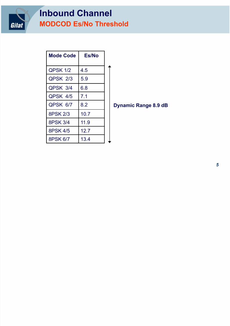
Inbound ChannelMODCOD Es/No Threshold
Mode Code Es/No
QPSK 1/2 4.5
QPSK 2/3 5.9QPSK 3/4 6.8
QPSK 4/5 7.1
QPSK 6/7 8.2
8PSK 2/3 10.7
8PSK 3/4 11.9
8PSK 4/5 12.7
8PSK 6/7 13.4
Dynamic Range 8.9 dB

8/12/2019 05 SkyEdge II Inbound Overview v6.1
http://slidepdf.com/reader/full/05-skyedge-ii-inbound-overview-v61 6/44
6
Inbound ChannelConfiguration Parameters
Symbol rates128, 160, 192, 256, 320, 384, 512, 640, 832, 1024,1536, 2048, 2560 Ksps.
Roll off factor
0.20
Inbound BW as low as 153.6KHz (BW = 128 Ksps x 1.20)
Frequency
BW = Sym bo l Rate x (1 + Roll off Factor)
Ampl i tude
B W

8/12/2019 05 SkyEdge II Inbound Overview v6.1
http://slidepdf.com/reader/full/05-skyedge-ii-inbound-overview-v61 7/44
7
SEII InboundIntroduction
The IB carries all the transmissions from the VSATs including:User Traffic
Initial Logon
Capacity Requests (Allocations requests)
Maintenance Information
Offers a Reliable communication link:
The MODCODs adaptation and reservation Access mechanisms permitno error correction (no retransmissions are needed) on the IB
The IB Is composed of one or more physical channels that includes oneor more Carrier Types (CT)

8/12/2019 05 SkyEdge II Inbound Overview v6.1
http://slidepdf.com/reader/full/05-skyedge-ii-inbound-overview-v61 8/44
8
Inbound ChannelCarrier Type CT
A Carrier Type (CT) is defined by its symbol rate and an arrangement ofslot types in a time frame
Up to four CTs can be configured per HSP
Slot Type (ST)The ST Is defined by its MODCOD and relative bandwidth inside CT
Several ST can be configures in a CT (up to 8 ST per HSP)
Each HSP has its own Time and Frequency Plan (TFP)
8/12/2019 05 SkyEdge II Inbound Overview v6.1
http://slidepdf.com/reader/full/05-skyedge-ii-inbound-overview-v61 9/44
9
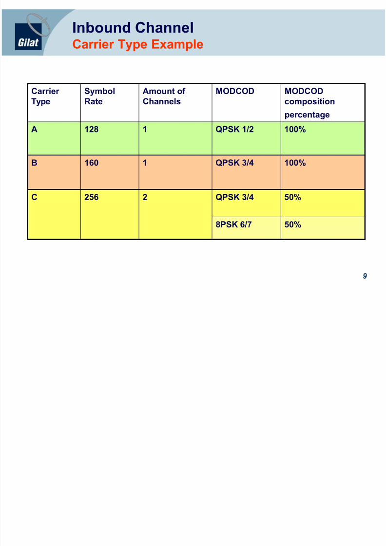
Inbound ChannelCarrier Type Example
CarrierType
SymbolRate
Amount ofChannels
MODCOD MODCODcomposition
percentage
A 128 1 QPSK 1/2 100%
B 160 1 QPSK 3/4 100%
C 256 2 QPSK 3/4 50%
8PSK 6/7 50%

8/12/2019 05 SkyEdge II Inbound Overview v6.1
http://slidepdf.com/reader/full/05-skyedge-ii-inbound-overview-v61 10/44
10
Inbound ChannelCarrier Type Example
Freq
Time
CT- B
C T- A
CT- C
CT- C
C
QPSK ½ QPSK ½ QPSK ½QPSK ½ QPSK ½ QPSK ½
8 P S K 6 / 7
QPSK ¾
8 P
S K 6 / 7
QPSK ¾
QPSK ¾ QPSK ¾QPSK ¾ QPSK ¾ QPSK ¾ QPSK ¾QPSK ¾
C A
8 P
S K 6 / 7
8 P S K 6 / 7
QPSK ¾
QPSK ¾
8 P
S K 6 / 7
8 P S K 6 / 7
8 P
S K 6 / 7
8 P S K 6 / 7
QPSK ¾
QPSK ¾ 8 P
S K
6 / 7
8 P S K 6 / 7
8 P S K 6 / 7
8 P
S K 6 / 7
QPSK ¾
QPSK ¾
8/12/2019 05 SkyEdge II Inbound Overview v6.1
http://slidepdf.com/reader/full/05-skyedge-ii-inbound-overview-v61 11/44
11
Inbound ChannelTime Frequency Plan (TFP)
Stop Freq
Time
Q6/7
Q 1/2 Q 1/2 Q 1/2 Q 1/2
Q6/7
Q6/7
Q3/4
Q6/7
Q6/7
Q6/7
Q3/4
Q3/4
Q 1/2 Q 1/2 Q 1/2 Q 1/2
Start Freq
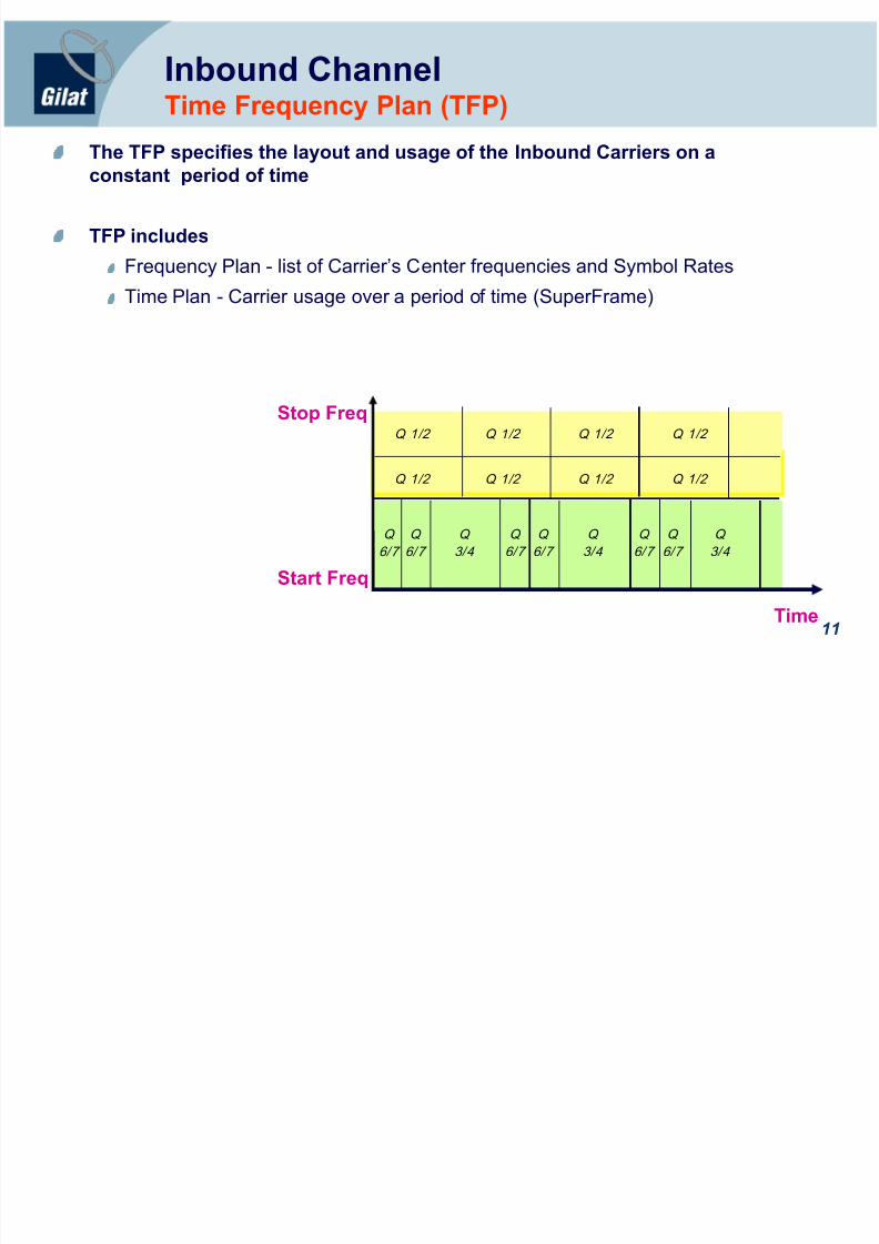
The TFP specifies the layout and usage of the Inbound Carriers on aconstant period of time
TFP includes
Frequency Plan - list of Carrier’s Center frequencies and Symbol Rates
Time Plan - Carrier usage over a period of time (SuperFrame)

8/12/2019 05 SkyEdge II Inbound Overview v6.1
http://slidepdf.com/reader/full/05-skyedge-ii-inbound-overview-v61 12/44
12
TFP is constructed to have a full repetition of a SuperFrame every 360 ms Allocation is performed every 40ms and published to all the VSATs
Each allocation round is independent. Each allocation round generates its own“allocation table” broadcasted to the network.
360 ms ecSuperFrame
CSC SYN CSC SYN CSC SYN CSC SYN
Freq
CSC SYN
TRF TRF TRF TRF TRF TRF TRF TRF
TRF TRF TRF TRF TRF TRF TRF TRF
Superframe
40 ms ec
Al locat ion Round
Time
Time Frequency Plan (TFP)Time Structure

8/12/2019 05 SkyEdge II Inbound Overview v6.1
http://slidepdf.com/reader/full/05-skyedge-ii-inbound-overview-v61 13/44
13
Time Frequency Plan (TFP)Time Slot Types
The Time-Frequency Plan (TFP) is composed of 3 slot types:Logon Burst (CSC- Common Signaling Channel) slot
Initial Logon
Synchronization (SYNC) slot
Maintenance (Es/No report about the OB)
SAC (Satellite Access Control) field for capacity requestsTraffic (TRF) slot
User Data
SAC field (capacity request as piggybacking)
StopFreq
Time
TR F Q
6/7
TRFQ 1/2
TRFQ
6/7
TRFQ
6/7
TRFQ
3/4
TRFQ
6/7
TRFQ
6/7
TRFQ
6/7
TRFQ
3/4
TRFQ
3/4 StartFreq
C
S
S
S
S
S
S
TRFQ 1/2
TRFQ 1/2
TRFQ 1/2
TRFQ 1/2 TRFQ 1/2
TRFQ 1/2
TRFQ 1/2
TRFQ 1/2
TRFQ 1/2
C
Slots of differenttypes on the samecarrier aremultiplexed intime in each CT
8/12/2019 05 SkyEdge II Inbound Overview v6.1
http://slidepdf.com/reader/full/05-skyedge-ii-inbound-overview-v61 14/44
14
Slot TypesCSC - Logon Burst Slot
Logon Burst (CSC) slotCarries VSAT initial network LogonIt is used in contention;
collisions may occur
The recommended default is to have one CSC per VSAT with a 10 second
interval (sizing spreadsheet)
CSC MODCODThe CSC slots are located in the most robust CT using the most robustMODCOD
If the most robust MODCOD uses 8PSK as the modulation scheme, thenthe system will define QPSK 6/7 as the MODCOD for the CSC slots
8/12/2019 05 SkyEdge II Inbound Overview v6.1
http://slidepdf.com/reader/full/05-skyedge-ii-inbound-overview-v61 15/44
15
Slot TypesCSC - Logon Burst Slot
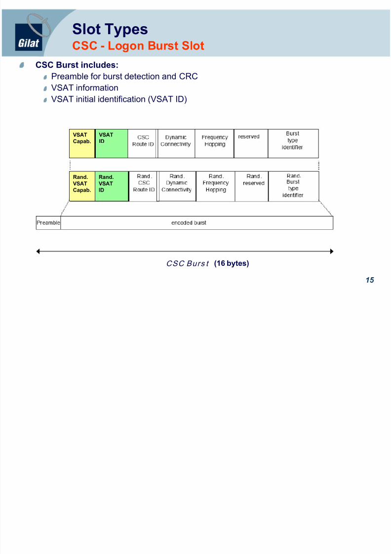
CSC Burst includes:Preamble for burst detection and CRCVSAT informationVSAT initial identification (VSAT ID)
VSATCapab. VSATID
Rand.VSATCapab.
Rand.VSATID
CSC Burs t (16 bytes)

8/12/2019 05 SkyEdge II Inbound Overview v6.1
http://slidepdf.com/reader/full/05-skyedge-ii-inbound-overview-v61 16/44
16
Slot TypesSync - Maintenance Slot
Sync slots are used for:Time, frequency and power maintenanceInitial capacity requestTransfer information about the received Es/No readingsVSAT Capability
Each logged on VSAT is allocated a Sync slot per second
Sync MODCODThe Sync will be located at the most robust CT using the most robustMODCOD
If most robust MODCOD uses 8PSK as the modulation scheme, then thesystem will define QPSK 6/7 as the MODCOD for the Sync slots
8/12/2019 05 SkyEdge II Inbound Overview v6.1
http://slidepdf.com/reader/full/05-skyedge-ii-inbound-overview-v61 17/44
17
Slot TypesSync - Maintenance Slot
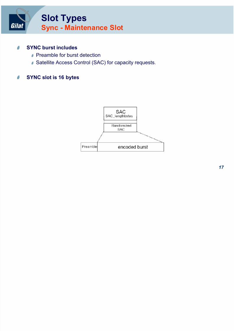
SYNC burst includesPreamble for burst detectionSatellite Access Control (SAC) for capacity requests.
SYNC slot is 16 bytes
8/12/2019 05 SkyEdge II Inbound Overview v6.1
http://slidepdf.com/reader/full/05-skyedge-ii-inbound-overview-v61 18/44
18
Slot TypesTRF - Traffic Slot
The TRF (Traffic) slot contains ATM cells that carry user data
Each Backbone packet is encapsulated over the ATM cells by AAL5 (RFC 2684)
Each TRF burst contains 1, 2 or 4 ATM cells. The default is 2.
TRF burst consists of:
Preamble for receiver detectionSAC (Satellite Access Control) field
Used for piggybacked capacity requests
2 ATM Cell
Each ATM cell carries 48 user traffic bytes (out of a total of 53 bytes)

8/12/2019 05 SkyEdge II Inbound Overview v6.1
http://slidepdf.com/reader/full/05-skyedge-ii-inbound-overview-v61 19/44
19
618 Bytes
Data Padding Trailer
600 Bytes
618 Bytes
48 48 48
485
SA C Preamble A TM Cell A TM Cell
48
Slot TypesTRF - Traffic Slot
IP
ATM
TRF Slot
Backbone
AAL5
8/12/2019 05 SkyEdge II Inbound Overview v6.1
http://slidepdf.com/reader/full/05-skyedge-ii-inbound-overview-v61 20/44
20
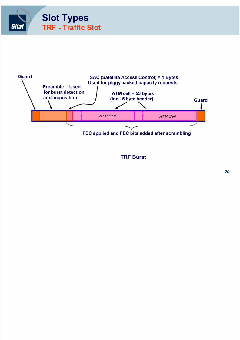
Slot TypesTRF - Traffic Slot
SAC (Satellite Access Control) = 4 Bytes
Used for piggy backed capacity requestsATM cell = 53 bytes
(incl. 5 byte header)
FEC applied and FEC bits added after scrambling
Guard
Guard
Preamble – Usedfor burst detectionand acquisition
TRF Burst
ATM Cell ATM Cell

8/12/2019 05 SkyEdge II Inbound Overview v6.1
http://slidepdf.com/reader/full/05-skyedge-ii-inbound-overview-v61 21/44
21
Gilat SEII IBBenefits
Uses multiple MODCODS
Supports robust slot for fade mitigation
Supports more efficient slots to take advantage of better weatherconditions
Uses multiple Carrier TypesYields better satellite utilization
Eliminates the need for additional carrier
8/12/2019 05 SkyEdge II Inbound Overview v6.1
http://slidepdf.com/reader/full/05-skyedge-ii-inbound-overview-v61 22/44
22
DVB-RCS TablesService Information (SI) Tables
SkyEdge II uses the DVB-S2 Outbound (forward link) to transmit allrelevant SI tables to define:
Satellite Position
Time-Frequency plan for Inbound channels
Frequency, power and time correctionsVSAT logon slots allocation
Individual VSAT parameters
Capacity/BW Allocation
Etc.
8/12/2019 05 SkyEdge II Inbound Overview v6.1
http://slidepdf.com/reader/full/05-skyedge-ii-inbound-overview-v61 23/44
23
Test Your Knowledge
1. Name the slot types in the TFP___________________________________ 2. How many allocation cycles are in a SuperFrame?___________________
3. Which type slots carries capacity requests? _____________________________
4. How many CT can be configured per HSP?______________________________
5. Calculate the required channel bandwidth for a carrier with symbol rate of 512Ksps. ___________________________________________________________
6. What is the user data size in each TRF? ________________________________
7. How many MODCODs can be configured in a CT?________________________
8. What is a CSC slot? _______________________________________________
9. What is carried by the Sync slot? A._________________ B.__________________C._______________________

8/12/2019 05 SkyEdge II Inbound Overview v6.1
http://slidepdf.com/reader/full/05-skyedge-ii-inbound-overview-v61 24/44
SkyEdgeII
Capacity Allocation Methods

8/12/2019 05 SkyEdge II Inbound Overview v6.1
http://slidepdf.com/reader/full/05-skyedge-ii-inbound-overview-v61 25/44
25
Bandwidth Allocation Methods
BW AllocationMethods Requ es t / Pr io r i ty Uns o l ic i t ed
Rate RBDC
(Rate Based DynamicCapacity)
C2P (VoIP)
AC (Admission Control)
ABS (Absolute)
High/Medium/Low
(Flywheel included here)
Volume VBDC
(Volume BasedDynamic Capacity)
or
AVBDC
(Absolute VolumeBased DynamicCapacity)
ABS (Absolute) FCD
(Free CapacityDistribution)
High/Medium/Low

8/12/2019 05 SkyEdge II Inbound Overview v6.1
http://slidepdf.com/reader/full/05-skyedge-ii-inbound-overview-v61 26/44
26
Rate Allocation MethodsRate Based Dynamic Capacity (RBDC)
RBDC - Rate Based Capacity RequestRate based capacity requests originated by the VSAT
Granularity of 2Kbps
A RBDC request is issued every 200 msec per priority
The VSAT refreshes AC, Abs and H, M,L requests once per second
Full multi-frequency allocation (even across different CTs)Prioritization by IB QoS mechanisms
C2P (VoIP) priority / AC (Admission Control) priority
Abs (Absolute) priority
High, Medium or Low flow priority
Used for Managed Multimedia Application (VoIP, Video), Trunk Mode (forABIS), CBR Applications and general non TCP traffic.

8/12/2019 05 SkyEdge II Inbound Overview v6.1
http://slidepdf.com/reader/full/05-skyedge-ii-inbound-overview-v61 27/44
27
Rate Allocation MethodsRBDC Priority Levels
C2P (Connection Control Protocol)AC (Admission Control) priority
Absolute, low jitter, low delay rate based requests Guaranteed bit rateallocation (explicit grant or reject)
Minimum jitter capacity request by uniform allocations in the SuperFrame(not more than 10 ms difference)
Highest priority in the system

8/12/2019 05 SkyEdge II Inbound Overview v6.1
http://slidepdf.com/reader/full/05-skyedge-ii-inbound-overview-v61 28/44
28
Rate Allocation MethodsRBDC Priority Levels
Abs (Absolute) PriorityGuaranteed rate based allocation requests
Priority used by the VSAT for allocation requests up to the CIR value
High, Medium and Low priorities
Weighted fair sharing rate based priority requestsNeither rate nor jitter guaranteed
Priority used by the VSAT for allocations up to the MIR value
Configurable on the DiffServ queues
8/12/2019 05 SkyEdge II Inbound Overview v6.1
http://slidepdf.com/reader/full/05-skyedge-ii-inbound-overview-v61 29/44
29
Rate Allocation MethodsRBDC Sources Requests
Managed VoIP ApplicationsUse C2P requests
Applications included in this criteria are detected and locally managed by theVSAT application layers
Automatic SIP recognition

8/12/2019 05 SkyEdge II Inbound Overview v6.1
http://slidepdf.com/reader/full/05-skyedge-ii-inbound-overview-v61 30/44
30
Rate Allocation MethodsRBDC Sources Requests
Trunk Traffic (SkyAbis Solution)Use AC RBDC allocation request
Abis traffic is dynamically measured for required satellite demand and low jitter
Trunk Mode parameter should be enabled and specific configuration is
required in the VSAT
8/12/2019 05 SkyEdge II Inbound Overview v6.1
http://slidepdf.com/reader/full/05-skyedge-ii-inbound-overview-v61 31/44
31
Rate Allocation MethodsRBDC Sources Requests
CBR (Constant Bit Rate) Allocates a fixed CBR to the VSATs
Used for any application that requires strict CBR
Uses an Absolute RBDC allocation request
Must be preconfigured on the VSAT
Requested immediately after logon

8/12/2019 05 SkyEdge II Inbound Overview v6.1
http://slidepdf.com/reader/full/05-skyedge-ii-inbound-overview-v61 32/44
32
Rate Allocation MethodsRBDC Sources Requests
Non TCP trafficUsed for Raw-IP and any UDP applications (TFTP, file-sharing, ICMP, etc.)
Up to CIR, use Abs RBDC allocation request
After CIR reached, use Low, Medium or High RBDC request
The HSP allocated BW according need and overall network demand
It is configurable by DiffServ VSAT queue configuration
8/12/2019 05 SkyEdge II Inbound Overview v6.1
http://slidepdf.com/reader/full/05-skyedge-ii-inbound-overview-v61 33/44
33
Rate Allocation MethodsTraffic Sense Flywheel
Flywheel MechanismOne of the heuristics mechanism employed in SEII
It is a rate based allocation mechanism that shortens response time
The mechanism is based on the assumption that an active VSAT will soonneed to transmit more traffic even if its DRPP queues are currently empty
When any traffic that passes through the VSAT, the flywheel mechanismwill be set for three seconds (but not before the DRPP queues are empty)
The three seconds are hard coded
The flywheel request is configurable in the VSAT by 2 Kbps steps
Flywheel may be totally disabled
Flywheel uses a Low RBDC request

8/12/2019 05 SkyEdge II Inbound Overview v6.1
http://slidepdf.com/reader/full/05-skyedge-ii-inbound-overview-v61 34/44
34
Volume Allocation MethodsVolume Based Dynamic Capacity (VBDC)
VBDC Volume Based Dynamic CapacityIt is a volume based capacity allocation dynamically requested by the VSAT
The VBDC request is issued every 100 msec for the total amount of trafficwhich accumulated since last VBDC (only the newly added traffic)
Prioritization by IB QoS mechanisms
Ab s (Abs olute) pr ior i ty
Low, Medium or High pr ior i ty
It is used for TCP type Traffic
AVBDC Absolute Volume Based Dynamic Capacity requests
This is a “health mechanism” used for recovery
This request type overwrite and replaces all previous VBDC requests
AVBDC is sent after timeout interval during which none of the VSAT’sVBDC requests were not allocated

8/12/2019 05 SkyEdge II Inbound Overview v6.1
http://slidepdf.com/reader/full/05-skyedge-ii-inbound-overview-v61 35/44
35
Rate Allocation MethodsVBDC Sources Requests
TCP TrafficFTP, HTTP, Telnet, POP3, SMTP, etc.
Up to CIR, use Abs VBDC/ AVBDC allocation requests
After CIR is reached, use Low, Medium or High VBDC/AVBDC requests
The HSP allocated BW according need and overall network demand
It is configurable by DiffServ VSAT queue configuration

8/12/2019 05 SkyEdge II Inbound Overview v6.1
http://slidepdf.com/reader/full/05-skyedge-ii-inbound-overview-v61 36/44
36
Free Capacity Distribution (FCD)
FCD - Free Capacity Distribution MechanismOne of the heuristics mechanism employed in SEII
It is a unsolicited volume based capacity allocation that assigns theunused capacity
The mechanism is based on the assumption that some unused capacitycan remain after all pending capacity requests have been processed
Allocated by the HSP without any request or signaling from the VSATs
The HSP allocates a configurable number of slots equally to each VSATs in“round robin” manner
The Free Capacity is distributed equally by the Hub to:
All on-line VSATsor
All idle VSATs

8/12/2019 05 SkyEdge II Inbound Overview v6.1
http://slidepdf.com/reader/full/05-skyedge-ii-inbound-overview-v61 37/44
Inbound Adaptivity

8/12/2019 05 SkyEdge II Inbound Overview v6.1
http://slidepdf.com/reader/full/05-skyedge-ii-inbound-overview-v61 38/44
38
ICM – 3 Dimensions of AdaptivityMultiple Dimensions of IB Adaptivity
Adaptive channel rate selection (ICM 1D)Each VSAT is allocated the appropriate symbol rate
Adaptive MODCOD selection (ICM 2D)
Each VSAT is allocated the best possible MODCOD from the plan
Adaptive Uplink Power Control (ICM 3D)
The BUC output power is increased or decreased based on the receivedsignal

8/12/2019 05 SkyEdge II Inbound Overview v6.1
http://slidepdf.com/reader/full/05-skyedge-ii-inbound-overview-v61 39/44
39
Multi-Channel Selection
Q ¾ Q ¾ Q ¾ Q ¾ Q ¾ Q ¾ Q ¾ Q ¾
Q ¾ Q ¾ Q ¾ Q ¾ Q ¾ Q ¾ Q ¾ Q ¾
Q ¾ Q ¾ Q ¾ Q ¾ Q ¾ Q ¾ Q ¾ Q ¾
Freq
Time
Q ¾ Q ¾
256ks/s
128ks/sQ ¾ Q ¾ Q ¾ Q ¾
Multi-Channel selection permits the adaptation of Symbol ratesAll carriers have their own symbol rateKnown also as ICM (IB Coding Modulation) 1D

8/12/2019 05 SkyEdge II Inbound Overview v6.1
http://slidepdf.com/reader/full/05-skyedge-ii-inbound-overview-v61 40/44
40
MODCOD Allocation
TRF are allocated on a more robust or more efficient MODCOD withinsame or even different channels of different Symbol RatesSymbol rate and MODCOD division optimized per network:
Different coverage areasDifferent VSAT capabilities / throughput requirements
Known also as ICM (IB Coding Modulation) 2D
Q ¾Q ¾Q ¾Q ¾Q ¾Q ¾Q ¾Q ¾
Q ¾Q ¾Q ¾Q ¾Q ¾Q ¾Q ¾Q ¾
Q ¾Q ¾Q ¾Q ¾Q ¾Q ¾Q ¾Q ¾
Freq
Time
Q ½Q ½
256ks/s
256ks/sQ ½Q ½ Q ½Q ½
8¾
8¾
86 /7
8¾
8¾
86 /7
8¾
8¾
86 /7
8¾
8¾ 256ks/s
1.1dB 4.3dB 1.3dBGain per change

8/12/2019 05 SkyEdge II Inbound Overview v6.1
http://slidepdf.com/reader/full/05-skyedge-ii-inbound-overview-v61 41/44
41
Power Loop
Also known as Power Adaptive Coding Modulation (P-ACM) or Known alsoas ICM (IB Coding Modulation) 3D
Remote Unit includes Linear BUC with adaptive power control
The VSAT can increase TX power as the link faces fade conditions
The VSAT determines its 1dB compression point and adapts TX power tochanging link conditions so that transmissions are received at a fixed level atthe satellite
When weather conditions worsen the VSAT first increases TX power untilreaches its limit, then robust MODCODs are used
Received E S /N 0(in OB to VSAT)
SYNC bursts(every second)
Decision toincrease/decrease

8/12/2019 05 SkyEdge II Inbound Overview v6.1
http://slidepdf.com/reader/full/05-skyedge-ii-inbound-overview-v61 42/44
42
Power Loop
The Power loop compensates for:Rain fade
Static attenuation (such as cable)
Satellite location offset and aging
Temperature and frequency effects on BUC gain
The BUC Saturation point is discovered by the Power Loop mechanism onceper hour
The VSAT increases SYNC bursts TX power and receives SYNC receptionpower readings from the hub until saturation is reached
Saturation: TX power increase doesn’t fully translate into Rx power increase
The Power loop is maintain used the Sync slots every second
During the Power loop process, TRF Transmission power is not affected

8/12/2019 05 SkyEdge II Inbound Overview v6.1
http://slidepdf.com/reader/full/05-skyedge-ii-inbound-overview-v61 43/44
43
Test Your Knowledge
1. Which allocation mechanism is guaranteed?____________________________
2. Describe two differences between Volume based and Rate Based CapacityRequests
__________________________________________________________________ __________________________________________________________________
3. Describe the Flywheel mechanism ____________________________________
4. What is AVBDC requests used for?____________________________________
5. How does the VSAT learn the Saturation point of the BUC? __________________________________________________________________
6. Can the same VSAT be allocated on a efficient or robust MODCODs indifferent CT?
__________________________________________________________________

8/12/2019 05 SkyEdge II Inbound Overview v6.1
http://slidepdf.com/reader/full/05-skyedge-ii-inbound-overview-v61 44/44
The En d