08-09 suspension design analysisedge.rit.edu/edge/rit mini-baja/public/2008-2009 suspension...
TRANSCRIPT
Jonathan Peyton Independent Design Study
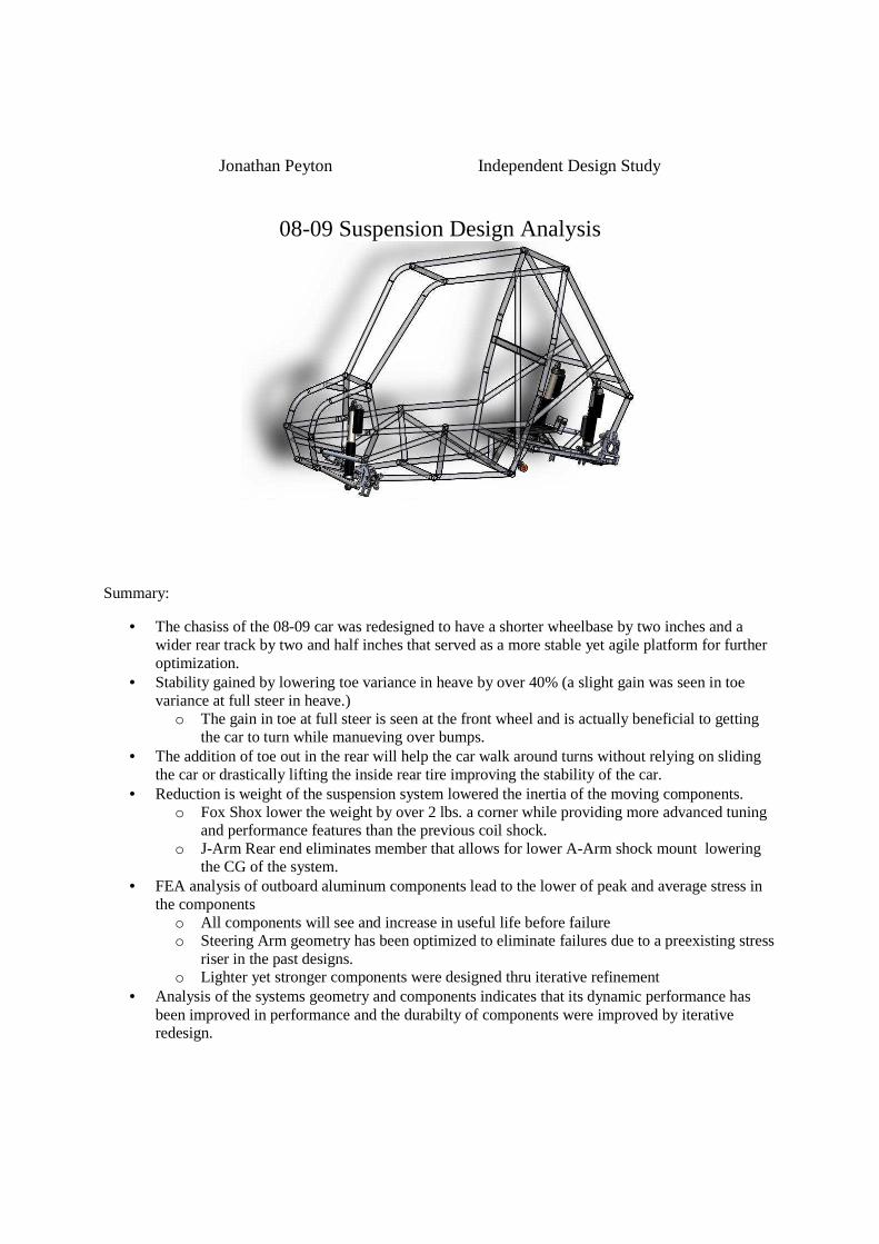
08-09 Suspension Design Analysis
Summary:
• The chasiss of the 08-09 car was redesigned to have a shorter wheelbase by two inches and a wider rear track by two and half inches that served as a more stable yet agile platform for further optimization.
• Stability gained by lowering toe variance in heave by over 40% (a slight gain was seen in toe variance at full steer in heave.)
o The gain in toe at full steer is seen at the front wheel and is actually beneficial to getting the car to turn while manueving over bumps.
• The addition of toe out in the rear will help the car walk around turns without relying on sliding the car or drastically lifting the inside rear tire improving the stability of the car.
• Reduction is weight of the suspension system lowered the inertia of the moving components. o Fox Shox lower the weight by over 2 lbs. a corner while providing more advanced tuning
and performance features than the previous coil shock. o J-Arm Rear end eliminates member that allows for lower A-Arm shock mount lowering
the CG of the system. • FEA analysis of outboard aluminum components lead to the lower of peak and average stress in
the components o All components will see and increase in useful life before failure o Steering Arm geometry has been optimized to eliminate failures due to a preexisting stress
riser in the past designs. o Lighter yet stronger components were designed thru iterative refinement
• Analysis of the systems geometry and components indicates that its dynamic performance has been improved in performance and the durabilty of components were improved by iterative redesign.
08-09 Mini Baja Suspension Design Objectives:
• Evaluate the performance of the past two years (06-07, 07-08) systems • Understand gains made in past two years suspensions designs. • Optimize suspension geometry with last year’s dynamic analysis results as a guideline. • Optimize components to save weight, improve dynamic characteristics of the car, and maintain
simplistic streamlined design for ease of manufacture.
08-09 Suspension Design Strategy:
• Map the front end of the 07-08 car in Optimum-K suspension analysis software to gain dynamic performance specifications of the past year’s car.
• Optimize front end to outperform the previous design in relation to: � Reduce toe variance in heave and at full steering input to achieve higher stability � Gain more steering angle at inner wheel from the same steering input from the driver. � Progress to fifteen degrees of wheel recession to prevent the car from landing nose down in
jumps and deliver smoother ride characteristics. • Obtain benefits to 06-07’s rear end through conversation, testing and speculative mapping(full
geometry lost due to poor file maintenance) • Redesisn the rear end with a “J”- arm layout and obtain a system that duplicates the functionality
of the past two year’s rear end designs. • Design a functional rear system with no rear toe link with variable toe out during compression to
aide cornering.
Results:
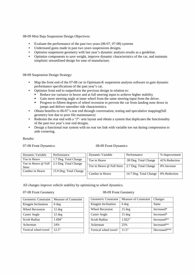
07-08 Front Dynamics: 08-09 Front Dynamics
All changes improve vehicle stability by optimizing to wheel dynamics.
07-08 Front Geometry 08-09 Front Geometry
Dynamic Variable Performance Toe in Heave 1.7 Deg. Total Change Toe in Heave @ Full Steer
2.5 Deg. Total Change
Camber in Heave 15.9 Deg. Total Change
Dynamic Variable Performance % Improvement
Toe in Heave .99 Deg. Total Change 41% Reduction
Toe in Heave @ Full Steer 2.7 Deg. Total Change 8% Increase
Camber in Heave 14.7 Deg. Total Change 8% Reduction
Geometric Constraint Measure of Constraint Changes
Kingpin Inclination 6 deg Same
Wheel Recession 15 deg Increased*
Caster Angle 15 deg Increased*
Scrub Radius 1.922” Increased**
Ackerman 25% Increased**
Vertical wheel travel 11.5” Decreased***
Geometric Constraint Measure of Constraint
Kingpin Inclination 6 deg
Wheel Recession 12 deg
Caster Angle 12 deg
Scrub Radius 1.694”
Ackerman 24%
Vertical wheel travel 12.5”
*The wheel recession angle was increased to improve stability over bumps and jumps the caster was changed to match wheel recession angle.
** The scrub radius and ackerman were increased to gain more steer with the same total rack displacement as the previous design.
*** The vertical wheel travel suffered a decrease due to the Fox Shox having approximately one inch less of compressible length.
Indicated above is the general layout to the 07-08 and 08-09 front geometries and basic dynamic performance to provide basis for quick comparison. The 07-08 system saw the best documentation of data by the team and also proved one of the highest potentials for great performance seen in any RIT Baja Car. Hence the 07-08 car served as a basis for comparison when designing this year’s car. The car saw the greatest stability over even the roughest terrain due to the low variance in toe while turning or straight motion over its full vertical travel. The main reason for the gain in stability was the addition of wheel recession to the rear and adding two more degrees to the front wheel recession. Wheel recession allows the wheel to travel backwards and up in compression making the ride smoother while jumping and provides better landing for the car. The rear of the car used trailing arm that followed the overall wheel path of 15 degrees of wheel recession and proved to be very effective. This provided to the layout for the wheel recession for the design of this year’s front and rear. Negatives to the 07-08 car were that it required riding on a razors edge of control. To make the car effectively corner with speed made the driver ride the border of bicycling the car and low speed cornering demanded perfect turn in. If the driver missed the apex of a low speed corner the car pushed or lifted both inner tires. The 06-07 car was known to be slightly slower but much more forgiving so a blend of these two cars’ “personalities” was the aim for this year’s car.
To begin to “frame” success the general dimensions of the car were modified in comparison to the 07-08 car. The wheelbase shrunk from 60” to 58” to ease low speed tight radius cornering. To address the risk of bicycling the rear end was widened from a track width of 44” to 46.5”. After these dimensions were decided the finer details were optimized in Optimum-K. The Optimum-K suspension analysis software was a huge advantage as compared to ADAMS as it was much more user friendly and comprehensive at the same time. Below is listed the general dynamic characteristics of the 08-09 rear of the car along with the geometric layout to the rear system.
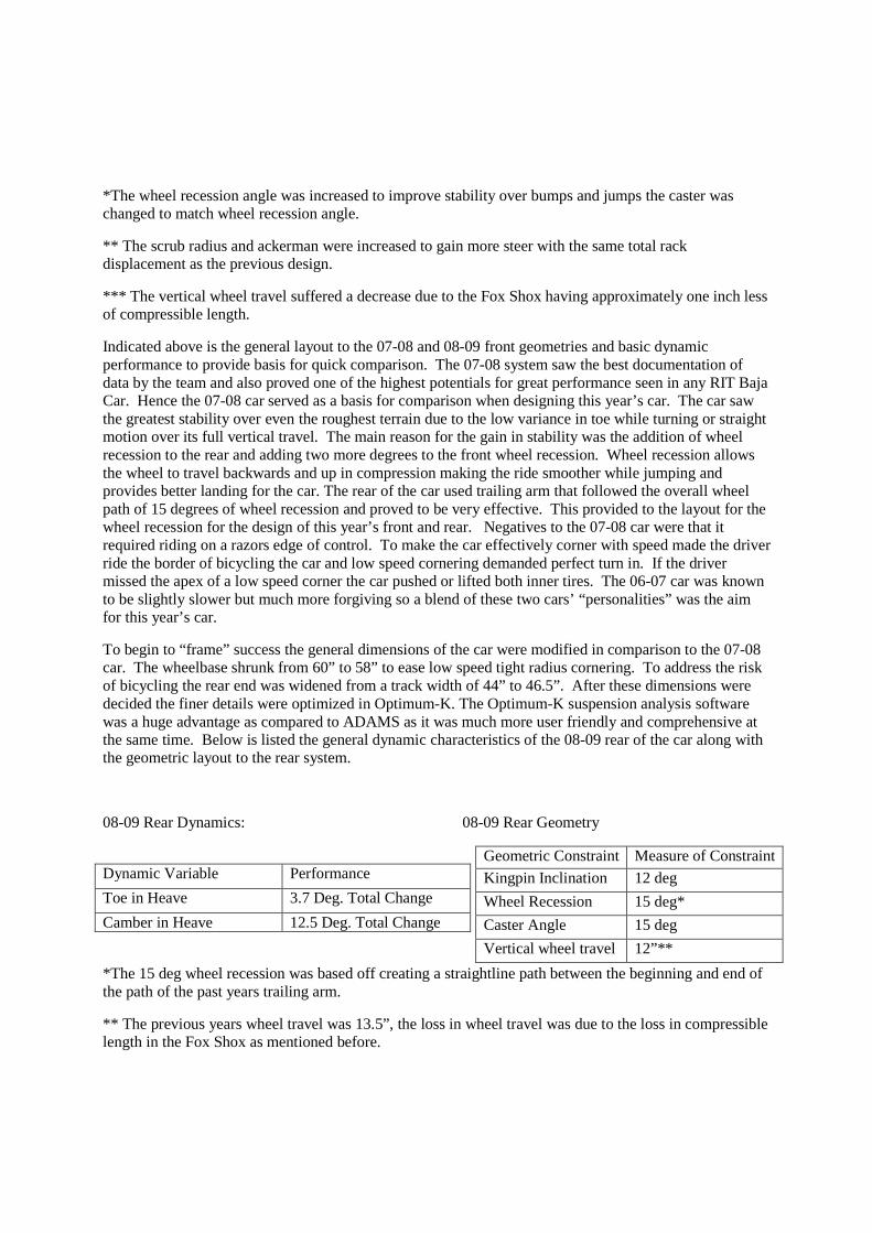
08-09 Rear Dynamics: 08-09 Rear Geometry
Dynamic Variable Performance
Toe in Heave 3.7 Deg. Total Change
Camber in Heave 12.5 Deg. Total Change
*The 15 deg wheel recession was based off creating a straightline path between the beginning and end of the path of the past years trailing arm.
** The previous years wheel travel was 13.5”, the loss in wheel travel was due to the loss in compressible length in the Fox Shox as mentioned before.
Geometric Constraint Measure of Constraint
Kingpin Inclination 12 deg
Wheel Recession 15 deg*
Caster Angle 15 deg
Vertical wheel travel 12”**
From the basic redesign to the wheel base and rear track width, the path is laid for a car that corners more sharply while providing greater stability. The quest for excellence continued with tuning in the geometry with Optimum-K to slightly lower camber changes and toe changes in the front. As for the rear it was decided that mild toe out in compression would be beneficial to help the rear end turn more efficiently in all turning scenarios. The benefits to toe out in compression were tested on with multiple inboard toe link points to connect to. The one problem was too much toe variance was seen in both compression and droop ranges causing the tires to slow the car in straight line motion over obstacles and greatly reducing stability. This testing with the 06-7 car made the team recognize the potential gains in cornering ability from the addition of toe out but had to wait for the next A-arm rear ended car as the 07-08 car was planned to be an trailing arm car. It was decided that toe out while driving straight should not be over 5 degrees in compression but could be varied with flexible bushing at the lower upright connection. This way straight line stability could be kept while aiding in sharp cornering as additional toe out would be gained from busing flex cause by side loads on the wheel during cornering. The additional gains would be controlled by testing several grades of polyurethane to find the optimum toe gains that would not sacrifice speed over obstacles while moving straight or cause the car to corner too sharply. As can be seen by comparing the tables listing the dynamic characteristics of the two cars the dynamic properties were tuned in and only varied slightly though there were several geometric differences.
The difference in wheel travel this year was a result of switching to a new shock that has an approximately one inch less in compressible length in comparison to the shocks we used on the 07-08 car. The shocks this year are the Fox Float Evol and were chosen for multiple reasons. Firstly the Floats are at least 2.5 pounds lighter as compared to the PEP shocks used the year before. The Fox’s also benefit from both low and high speed bound dampening adjustment, also as they are an air shock they a truly progressive in spring rate and have higher resolution in all tuning variables compared to the PEP’s allowing for the optimum tuning to be obtained. The low speed bound dampening will be used to tune in cornering and jump face(lip) characteristics while the high speed compression tuning will address bumps. This way a plush ride can be achieved without sacrificing optimal roll stiffness. Also spring rates had to be changed by removing the shock and disassembling the spring stack and having then to compress the springs to set the proper preload. This was time consuming and at times dangerous. Now all tuning can be done with the shocks on the car by twisting knobs and adding or releasing air pressure from two filling locations. This aspect of these shocks will prove time saving and extremely useful during the race season.
One difference in the steering this year is the longer scrub radius. This was slightly lengthened to give the driver slightly more feel in the steering. The scrub radius is now approximately 13% longer resulting in that much more force needed to be input by the driver at the wheel. It should return the car to a similar “feel” to the 06-07 car that most drivers preferred over the 07-08 car. The steering also saw an improvement is slightly more steer angle at the wheel with the same rack displacement as last year. The inside wheel sees an increase of a little over a degree to help cornering as it causes the wheel to nearly skid and assist the car in rotating about its center. On the outside wheel the increase is only a half of a degree but will also aide in helping the car in low speed cornering. The changes in steering still maintain the basic Ackerman geometry of having approximately ten degrees difference in steering angle between the inner and outer wheel at ride height. This is accomplised thru the steering arm geometry.
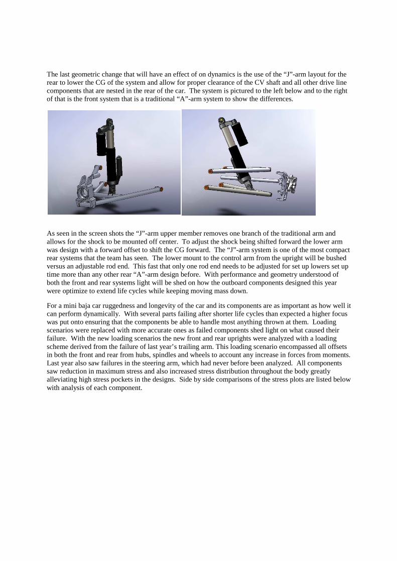
The last geometric change that will have an effect of on dynamics is the use of the “J”-arm layout for the rear to lower the CG of the system and allow for proper clearance of the CV shaft and all other drive line components that are nested in the rear of the car. The system is pictured to the left below and to the right of that is the front system that is a traditional “A”-arm system to show the differences.
As seen in the screen shots the “J”-arm upper member removes one branch of the traditional arm and allows for the shock to be mounted off center. To adjust the shock being shifted forward the lower arm was design with a forward offset to shift the CG forward. The “J”-arm system is one of the most compact rear systems that the team has seen. The lower mount to the control arm from the upright will be bushed versus an adjustable rod end. This fast that only one rod end needs to be adjusted for set up lowers set up time more than any other rear “A”-arm design before. With performance and geometry understood of both the front and rear systems light will be shed on how the outboard components designed this year were optimize to extend life cycles while keeping moving mass down.
For a mini baja car ruggedness and longevity of the car and its components are as important as how well it can perform dynamically. With several parts failing after shorter life cycles than expected a higher focus was put onto ensuring that the components be able to handle most anything thrown at them. Loading scenarios were replaced with more accurate ones as failed components shed light on what caused their failure. With the new loading scenarios the new front and rear uprights were analyzed with a loading scheme derived from the failure of last year’s trailing arm. This loading scenario encompassed all offsets in both the front and rear from hubs, spindles and wheels to account any increase in forces from moments. Last year also saw failures in the steering arm, which had never before been analyzed. All components saw reduction in maximum stress and also increased stress distribution throughout the body greatly alleviating high stress pockets in the designs. Side by side comparisons of the stress plots are listed below with analysis of each component.

Front Upright analysis: The loading scenario for the front and rear uprights took half the vehicle weight and through the spindle/hub offset input 3g 4g and 5g loads in the longitudinal vertical and lateral planes. This resulted in a 1250lb-in moment from the longitudinal load, 1798lb-in from the vertical and a lateral of 6130 lb-in. Also a torque was applied from the brakes of 2040lb-in. Even with a five percent reduction in volume thus a five percent reduction in weight (as both uprights are produced from 7075-T6 Aluminum,) the 08-09 upright still saw a much better overall stress distribution as seen above as most of the body is dark blue compared to the 07-08 which is a bright blue. The max stress seen in the 08-09 upright also dropped resulting in a higher factor of safety and approximately double the life cycles before failure. Last year saw no upright failure but obvious wear was apparent. The wear was noted at the upper rod end mount, this year’s and last year’s now run a sleeved mount. The sleeve is 4340 and has a top hat to distribute mounting forces. The max stress indicated on the stress plot of the 08-09 upright was ignored as the stress one node or two over from it dropped severely and discussions with professors indicate that the stress rise is a combination of geometry and mesh shape. If more computing capability was available the mess would be refined in all areas with red and yellow and stress would lower due to correct mesh geometry. So a value for max stress was pulled from a node close to the max stress indicated. The stress used for life cycle calculations for the 07-08 upright was 48 ksi versus 42.9 in the 08-09 upright, this resulted in a 14% increase in factor of safety and 92% increase in life cycles to failure from 1.28 x 10^5 cycle to 2.46 x 10^5 life cycles to failure. With this analysis it is clear to see the improvement of this year’s front upright.
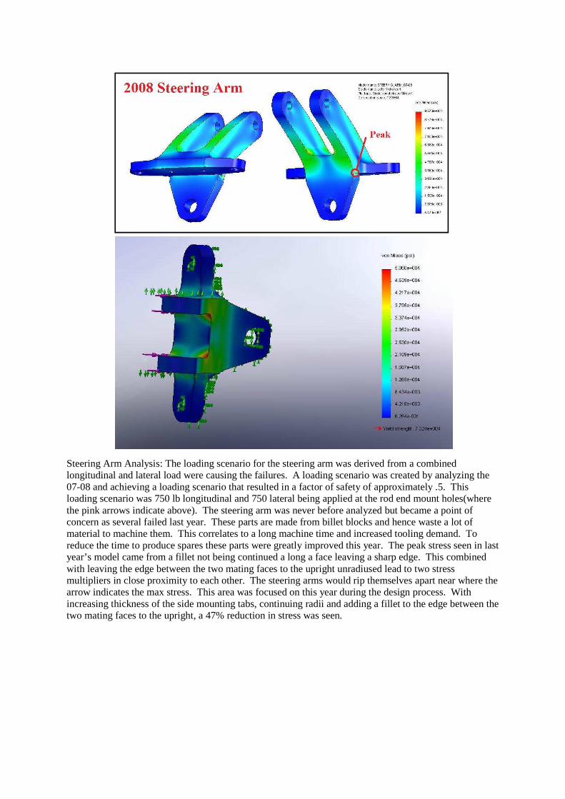
Steering Arm Analysis: The loading scenario for the steering arm was derived from a combined longitudinal and lateral load were causing the failures. A loading scenario was created by analyzing the 07-08 and achieving a loading scenario that resulted in a factor of safety of approximately .5. This loading scenario was 750 lb longitudinal and 750 lateral being applied at the rod end mount holes(where the pink arrows indicate above). The steering arm was never before analyzed but became a point of concern as several failed last year. These parts are made from billet blocks and hence waste a lot of material to machine them. This correlates to a long machine time and increased tooling demand. To reduce the time to produce spares these parts were greatly improved this year. The peak stress seen in last year’s model came from a fillet not being continued a long a face leaving a sharp edge. This combined with leaving the edge between the two mating faces to the upright unradiused lead to two stress multipliers in close proximity to each other. The steering arms would rip themselves apart near where the arrow indicates the max stress. This area was focused on this year during the design process. With increasing thickness of the side mounting tabs, continuing radii and adding a fillet to the edge between the two mating faces to the upright, a 47% reduction in stress was seen.
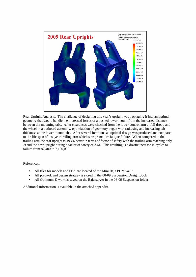
Rear Upright Analysis: The challenge of designing this year’s upright was packaging it into an optimal geometry that would handle the increased forces of a bushed lower mount from the increased distance between the mounting tabs. After clearances were checked from the lower control arm at full droop and the wheel in a outboard assembly, optimization of geometry began with radiusing and increasing tab thickness at the lower mount tabs. After several iterations an optimal design was produced and compared to the life span of last year trailing arm which saw premature fatigue failure. When compared to the trailing arm the rear upright is 193% better in terms of factor of safety with the trailing arm reaching only .9 and the new upright hitting a factor of safety of 2.64. This resulting is a drastic increase in cycles to failure from 82,400 to 7,190,000.
References:
• All files for models and FEA are located of the Mini Baja PDM vault • All prework and design strategy is stored in the 08-09 Suspension Design Book • All Optimum-K work is saved on the Baja server in the 08-09 Suspension folder
Additional information is available in the attached appendix.

Suspension Definitions:
Camber: Measure of angle of the wheel’s tilt vertically towards or away from the vehicle’s center. Negative camber indicate that the wheel’s top is tilted towards the center of the car and positive camber is when the top of the wheel is further away from the center of the car then the bottom of the wheel.
Toe: It is the relationship between the front and rear of the wheel as compared to the center of the vehicle. Toe out or negative toe is when the front of the wheel is pointed away from the center of the car. Toe in or positive toe is when the front of the wheel is closer to the center of the car than the rear of the wheel.
Caster: Relationship between the upper and lower suspension mounts at the wheel upright in respect to the side view of the car.
Kingpin: Measure of the angle between the upper and lower outer A- Arm mounts at the wheel in relation to the center of the car. This angle is measured from the front view of the car and usually the upper mount is closer to the center of the car in comparison to the lower mount.
Wheel recession: Measure of the angle created between the horizontal and the control arm’s rotational axis. This angle is measure from creating a line from the inboard mounts and measuring the angle between that line and the ground(level horizon), this angle can be measured from the side view of the car. In a car equipped with wheel recession the wheel does not simply travel vertical through its wheel travel it also moves horizontally towards the rear of the car aiding in stability over bumps and landing.
Heave: Motion of the vehicle up and down. Down is negative and up is positive. This motion is analyzed to measure dynamics of the suspension in compression(neg. heave) and droop(pos. heave.)
Steer angle: Same measure as toe but specifically from steering input versus toe that is created from wheel motion in vertical travel.
Ackerman Steering: Steering geometry that allows for a larger steering angle at the inner tire compared the outside wheel to address smaller turning radius at the inner wheel.
Scrub Radius: Distance between the centerline of the wheel and the kingpin angle extended to the ground.
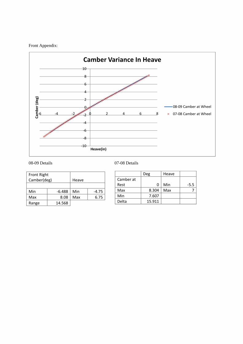
Front Appendix:
08-09 Details 07-08 Details
-10
-8
-6
-4
-2
0
2
4
6
8
10
-6 -4 -2 0 2 4 6 8
Ca
mb
er
(de
g)
Heave(in)
Camber Variance In Heave
08-09 Camber at Wheel
07-08 Camber at Wheel
Front Right
Camber(deg) Heave
Min -6.488 Min -4.75
Max 8.08 Max 6.75
Range 14.568
Deg Heave
Camber at
Rest 0 Min -5.5
Max 8.304 Max 7
Min 7.607
Delta 15.911

08-09 Details 07-08 Details
-1.6
-1.4
-1.2
-1
-0.8
-0.6
-0.4
-0.2
0
0.2
0.4
-8 -6 -4 -2 0 2 4 6 8
To
e (
de
g)
Heave (in)
Front Toe Variance in Heave
08-09 Toe Varience
07-08 Toe Varience
Front Toe
Right(deg) Heave
Min -0.77 Min -4.75
Max 0.213 Max 6.75
Range 0.983
Toe at
Rest 0 Heave
Max 1.485 Min -5.5
Min -0.232 Max 7
Delta 1.717
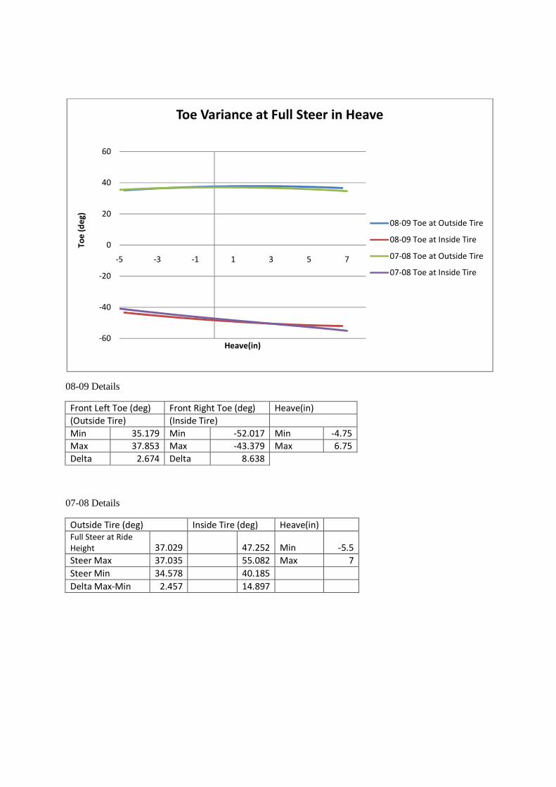
08-09 Details
Front Left Toe (deg) Front Right Toe (deg) Heave(in)
(Outside Tire) (Inside Tire)
Min 35.179 Min -52.017 Min -4.75
Max 37.853 Max -43.379 Max 6.75
Delta 2.674 Delta 8.638
07-08 Details
Outside Tire (deg) Inside Tire (deg) Heave(in)
Full Steer at Ride
Height 37.029 47.252 Min -5.5
Steer Max 37.035 55.082 Max 7
Steer Min 34.578 40.185
Delta Max-Min 2.457 14.897
-60
-40
-20
0
20
40
60
-5 -3 -1 1 3 5 7
To
e (
de
g)
Heave(in)
Toe Variance at Full Steer in Heave
08-09 Toe at Outside Tire
08-09 Toe at Inside Tire
07-08 Toe at Outside Tire
07-08 Toe at Inside Tire
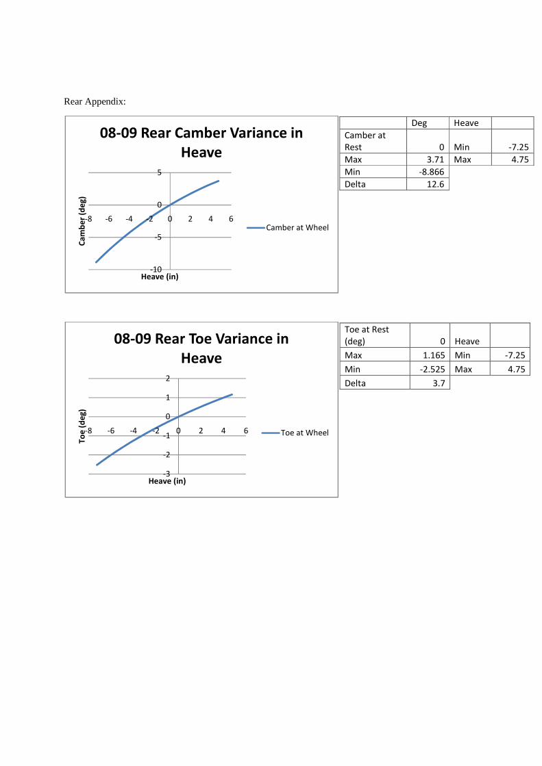
Rear Appendix:
-10
-5
0
5
-8 -6 -4 -2 0 2 4 6
Ca
mb
er
(de
g)
Heave (in)
08-09 Rear Camber Variance in
Heave
Camber at Wheel
-3
-2
-1
0
1
2
-8 -6 -4 -2 0 2 4 6
To
e (
de
g)
Heave (in)
08-09 Rear Toe Variance in
Heave
Toe at Wheel
Deg Heave
Camber at
Rest 0 Min -7.25
Max 3.71 Max 4.75
Min -8.866
Delta 12.6
Toe at Rest
(deg) 0 Heave
Max 1.165 Min -7.25
Min -2.525 Max 4.75
Delta 3.7