suspension design casestudy
TRANSCRIPT

Suspension Design Case Study
Purpose
• Suspension to be used on a small (lightweight) formula style racecar.
• Car is intended to navigate tight road courses
• Surface conditions are expected to be relatively smooth
Performance Design Parameters
• For this case the main objective is to optimize mechanical grip from the tire.
• This is achieved by considering as much tire information as possible while designing the suspension
• Specific vehicle characteristics will be considered.
Considerations
• Initially the amount of suspension travel that will be necessary for this application must be considered.– One thing that is often overlooked in a four
wheeled vehicle suspension design is droop travel.
• Depending on the expected body roll the designer must allow adequate droop travel.

Introduction

Components
• Upper A-arm– The upper A-arm serves to
carry some of the load generated on the suspension by the tire.
– This force is considerably less then the load carried by the lower A-arm in a push rod set-up
– The arm only has to provide a restoring force to the moment generated by the tire on the lower ball joint
Components
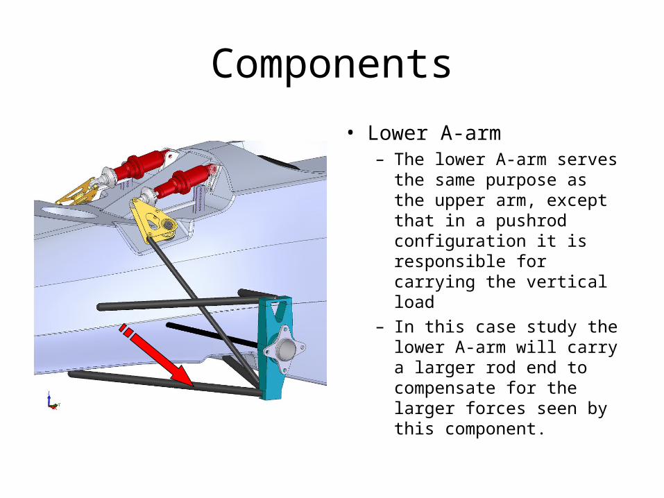
• Lower A-arm– The lower A-arm serves
the same purpose as the upper arm, except that in a pushrod configuration it is responsible for carrying the vertical load
– In this case study the lower A-arm will carry a larger rod end to compensate for the larger forces seen by this component.

Components
• Upright– The upright serves several
purposes in the suspension• Connects the upper A-
arm, lower A-arm, steering arm, and the tire
• Carries the spindle and bearing assembly
• Holds the brake caliper in correct orientation with the rotor
• Provides a means for camber and castor adjustment

Components
• Spindle– Spindle can come in two
basic configurations • Live spindle• Fixed spindle
– In the live spindle configuration the whole spindle assembly rotates and carries the tire and wheel
– The fixed spindle configuration carries a hub assembly which rotates about the spindle
– Both configurations carry the brake rotor

Live Vs. Fixed Spindle Advantages and Disadvantages
• Live Spindle :– Less parts– Lighter weight if designed
correctly– More wheel offset– Bearing concerns– Retention inside of the
upright assembly• Fixed spindle
– Simple construction– Hub sub-assembly– Spindle put in considerable
bending– More components, and
heavier
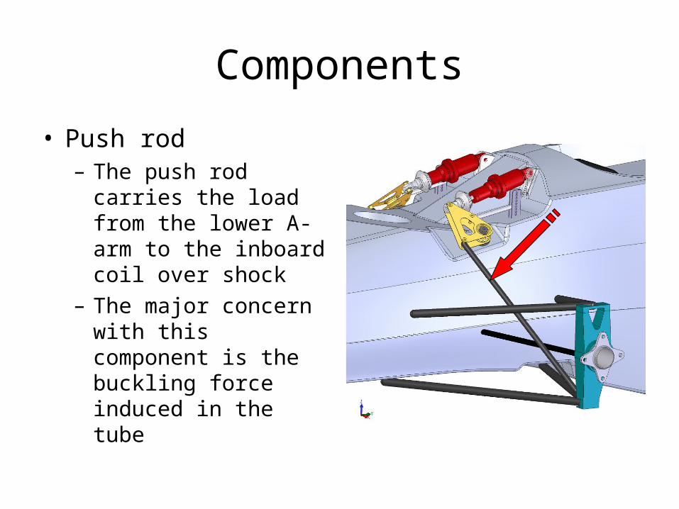
Components
• Push rod– The push rod carries
the load from the lower A-arm to the inboard coil over shock
– The major concern with this component is the buckling force induced in the tube

Components
• Toe rod (steering link)– The toe rod serves as a
like between the steering rack inboard on the vehicle
– The location of the ends of this like are extremely critical to bump steer and Ackermann of the steering system
– This link is also used to adjust the amount of toe-out of the wheels

Components
• Bellcrank– This is a common racing
description of the lever pivot that translates to motion of the push rod into the coil over shock
– The geometry of this pivot can be designed to enable the suspension to have a progressive or digressive nature
– This component also offers the designer the ability to include a motion ratio in the suspension

Components
• Coil-over Shock Absorber– This component
carries the vehicle corner weight
– It is composed of a coil spring and the damper
– This component can be used to adjust ride height, dampening, spring rate, and wheel rate
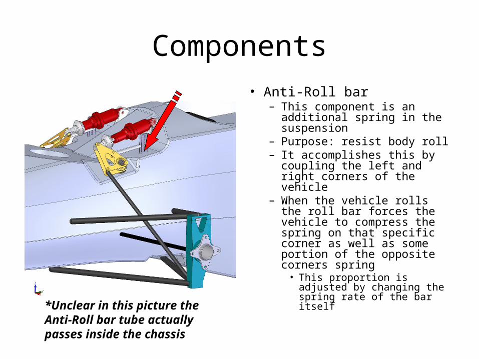
Components
• Anti-Roll bar– This component is an
additional spring in the suspension
– Purpose: resist body roll– It accomplishes this by
coupling the left and right corners of the vehicle
– When the vehicle rolls the roll bar forces the vehicle to compress the spring on that specific corner as well as some portion of the opposite corners spring
• This proportion is adjusted by changing the spring rate of the bar itself*Unclear in this picture the
Anti-Roll bar tube actually passes inside the chassis

Beginning the Design Process
• Initially the suspension should be laid out from a 2-D front view
• Static and dynamic camber should be defined during this step
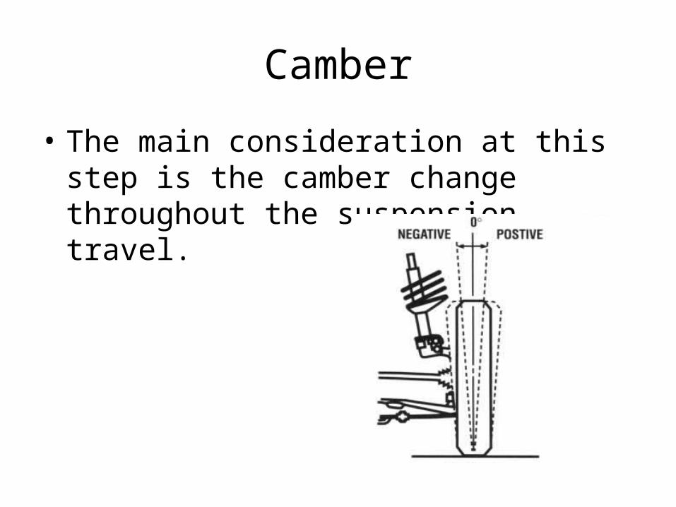
Camber
• The main consideration at this step is the camber change throughout the suspension travel.
Camber• Static Camber
– Describes the camber angle with loaded vehicle not in motion
• Dynamic Camber– Describes the camber angle of a corner at any
instant during a maneuver i.e.: cornering, launching, braking
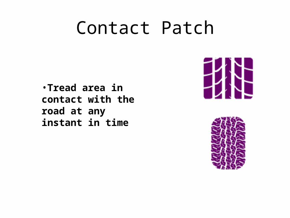
Contact Patch
•Tread area in contact with the road at any instant in time
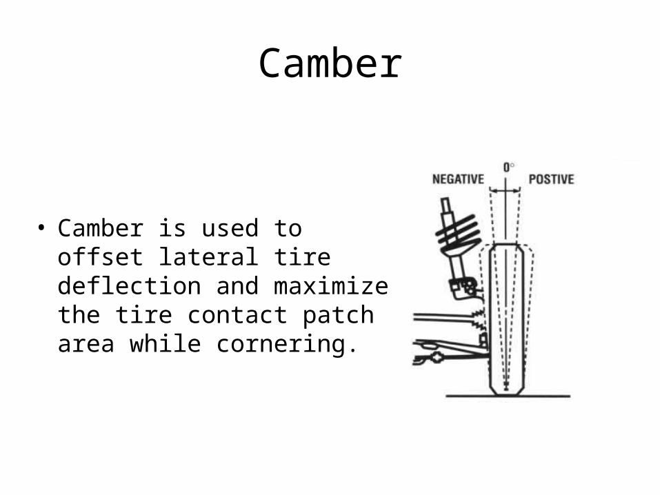
Camber
• Camber is used to offset lateral tire deflection and maximize the tire contact patch area while cornering.

Camber
• Negative Camber angles
– good for lateral acceleration, cornering
– bad for longitudinal acceleration, launching/braking
This is because the direction of the tire deflection is obviously not the same for these two situations
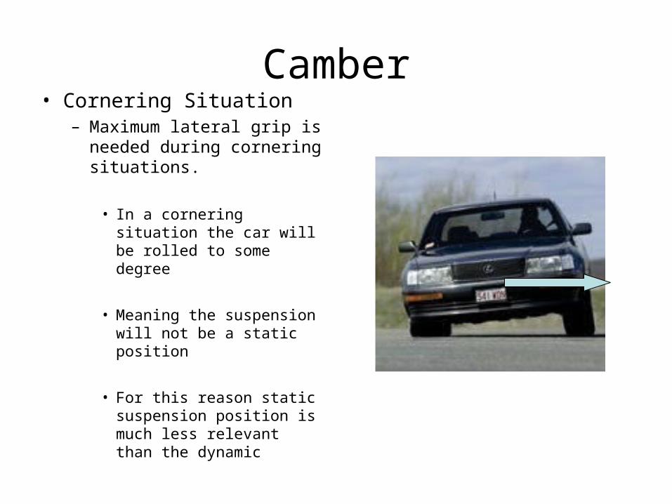
Camber• Cornering Situation
– Maximum lateral grip is needed during cornering situations.
• In a cornering situation the car will be rolled to some degree
• Meaning the suspension will not be a static position
• For this reason static suspension position is much less relevant than the dynamic

Camber• Launch/Braking Situation
– Maximum longitudinal grip is needed during launch/brake situations.
• In a launch/brake situation the car will be pitched to some degree
• Suspension will not be in a static position
Compromise
• It is apparent that the suspension is likely to be at the same position for some cornering maneuvers as it is during launching/braking maneuvers
– For this reason we must compromise between too little and too much negative camber
– This can be approximated with tire data and often refined during testing

Defining Camber
• Once we set our static camber we must adjust our dynamic camber curves
– This is done by adjusting the lengths of the upper and lower A-arms and the position of the inboard and out board pivots
– These lengths and locations are often driven by packaging constraints
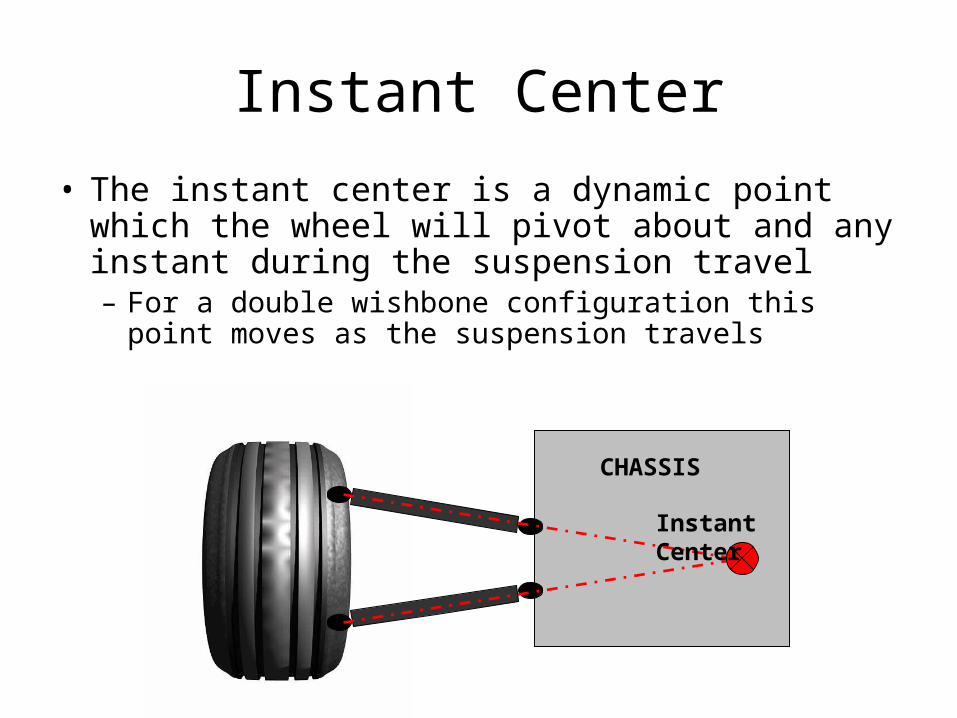
Instant Center
• The instant center is a dynamic point which the wheel will pivot about and any instant during the suspension travel– For a double wishbone configuration this point moves
as the suspension travels
CHASSIS
Instant Center
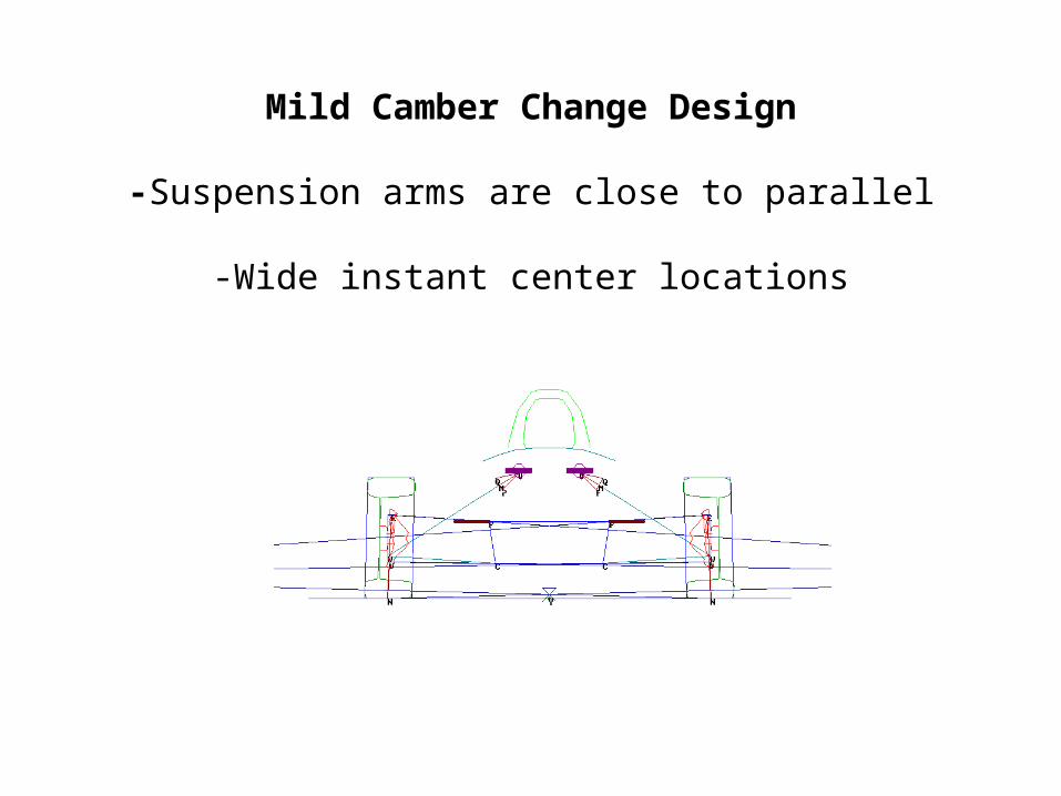
Mild Camber Change Design
-Suspension arms are close to parallel
-Wide instant center locations
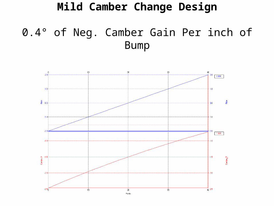
Mild Camber Change Design
0.4° of Neg. Camber Gain Per inch of Bump
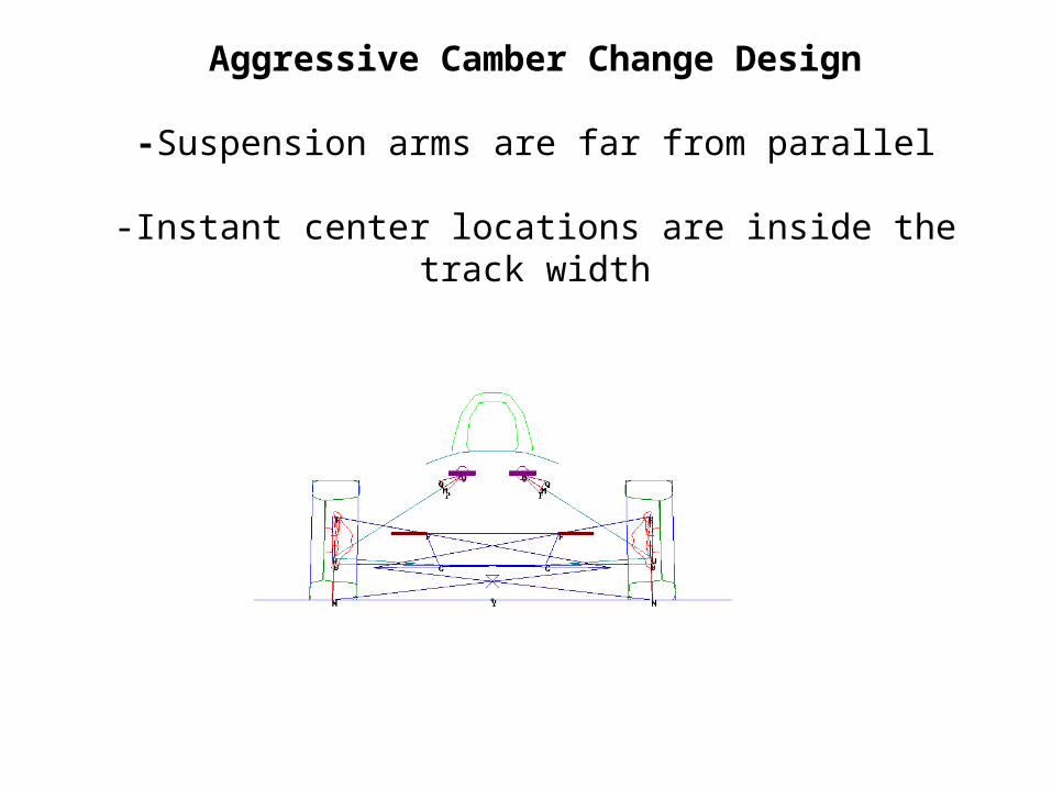
Aggressive Camber Change Design
-Suspension arms are far from parallel
-Instant center locations are inside the track width

More Aggressive Camber Change Design1.4° of Neg. Camber Gain Per inch of Bump
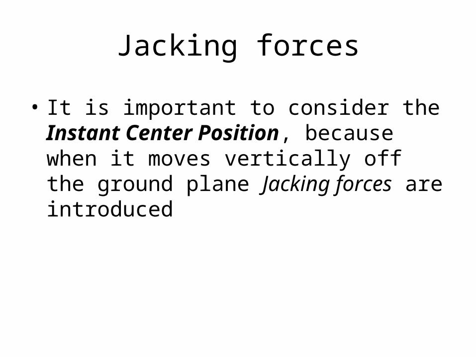
Jacking forces
• It is important to consider the Instant Center Position, because when it moves vertically off the ground plane Jacking forces are introduced

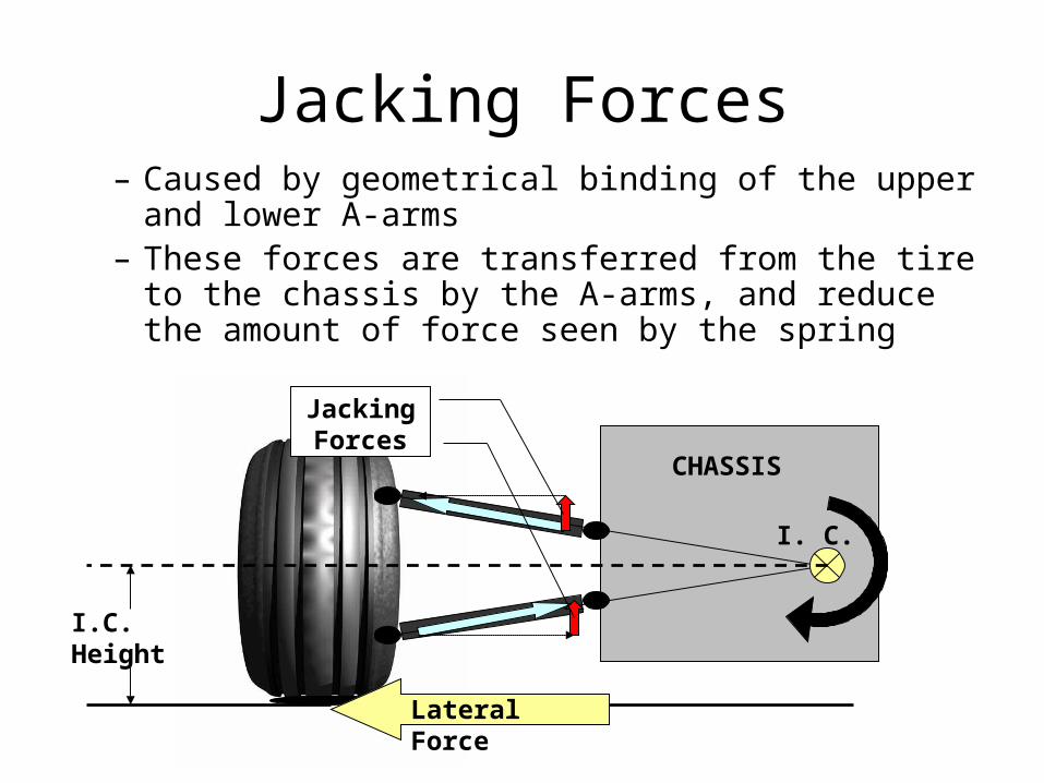
Jacking forces
• Caused during cornering by a moment– Force: lateral traction force of tire– Moment arm: Instant Center height– Moment pivot: Instant center
CHASSIS
Instant Center
Lateral Force Ground
I.C. Height
Jacking Forces
CHASSIS
I. C.
Lateral Force
I.C. Height
– Caused by geometrical binding of the upper and lower A-arms
– These forces are transferred from the tire to the chassis by the A-arms, and reduce the amount of force seen by the spring
Jacking Forces
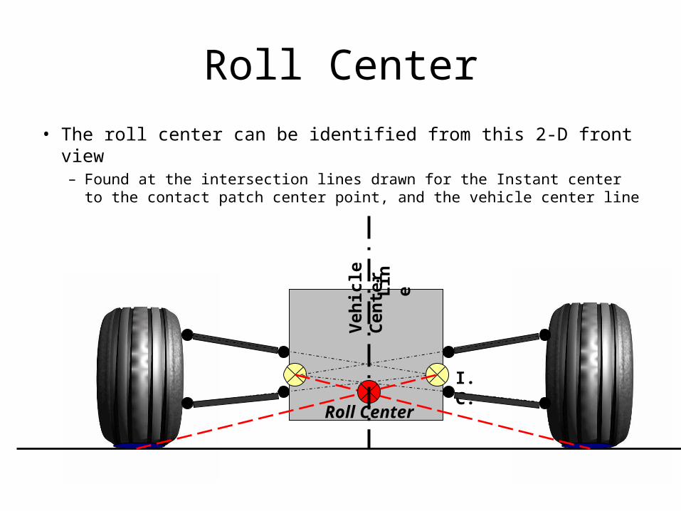
Roll Center
• The roll center can be identified from this 2-D front view– Found at the intersection lines drawn for the Instant center to the
contact patch center point, and the vehicle center line
I. C.
Roll Center
Veh
icle
Cen
ter
Lin
e

Roll Center
• For a parallel-Iink Situation the Roll Center is found on the ground plane
Roll Center
Veh
icle
Cen
ter
Lin
e

Significance of the Roll Center
• Required Roll stiffness of the suspension is determine by the roll moment. Which is dependant on Roll center height
Roll Center
Sprung Mass C.G.

Roll Moment• Present during lateral acceleration (the cause of body roll)
– Moment Arm: B = Sprung mass C.G. height – Roll center height
– Force:F = (Sprung Mass) x (Lateral Acceleration)
R. C.
Sprung Mass C.G.
B

Roll Axis
• To consider the total vehicle you must look at the roll axis
Roll AxisRear Roll Center
Front Roll Center
Sprung Mass C.G.

Side View
• The next step will be to consider the response of the suspension geometry to pitch situation– For this we will move to a 2-D side-view
Inboard A-arm pivot points
GroundFront Rear
CHASSIS

Anti-Features
• By angling the A-arms from the side jacking forces are created– These forces can be used in the design to provide
pitch resistance
GroundFront Rear
CHASSIS
Anti-DiveAnti-Lift
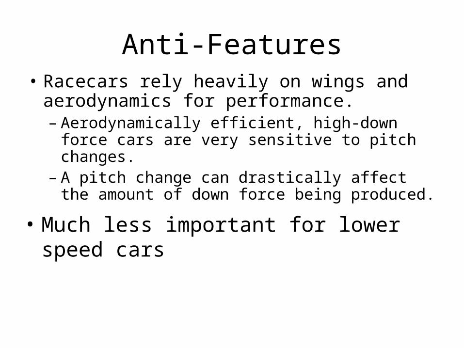
Anti-Features• Racecars rely heavily on wings and
aerodynamics for performance.– Aerodynamically efficient, high-down force
cars are very sensitive to pitch changes. – A pitch change can drastically affect the
amount of down force being produced.
• Much less important for lower speed cars
Pitch Center
Pitch Center
• The pitch center can be identified from this 2-D side view– Found at the intersection lines drawn for the
Instant center to the contact patch center point

Pitch Center
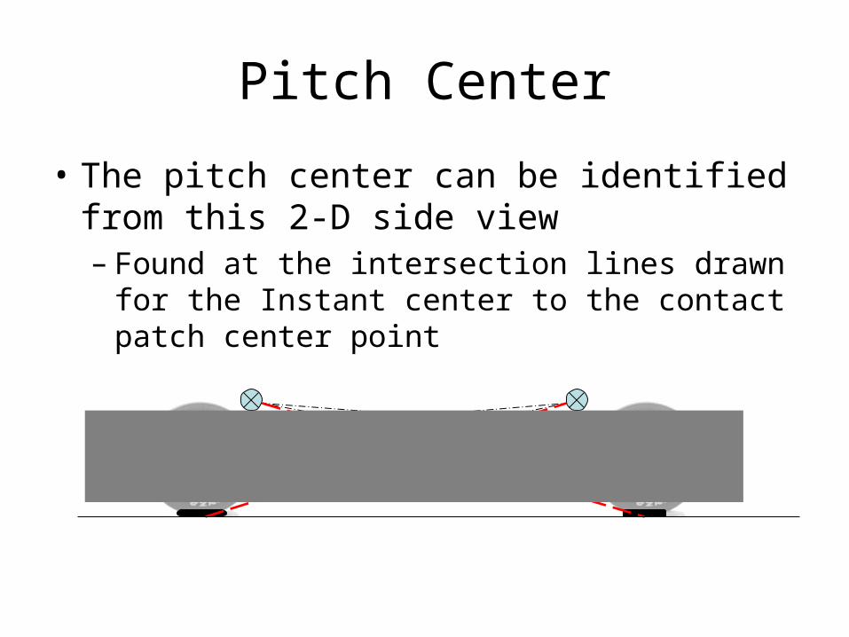
Pitch Center
• The pitch center can be identified from this 2-D side view– Found at the intersection lines drawn for the
Instant center to the contact patch center point

Pitch Moment
Pitch Center
• Present during longitudinal acceleration– Moment Arm: B = Sprung mass C.G. height – Roll center height
– Force:F = (Sprung Mass) x (Longitudinal Acceleration)
B
F