09 000 383 std with fan mv-1 - proair 000 383 -std with fan mv... · page 1 of 52 product: install...
TRANSCRIPT

Page 1 of 52
PRODUCT: Install Instructions, MV-1 C/O Std, With Aux Fan
RELEASE DATE: 2/28/14
REVISION DATE: 9/30/2014
PART NUMBER: 09 000 383 Rev C
Parts List
(1) 01 000 027 Switch, 4 Position Blower (1) 04 000 007 Hose, 1/2 ID Drain, 6”
(1) 01 000 087 Harn, Resistor (1) 04 000 078 Tube, Convo 1/2” x 24”
(2) 01 000 136 Relay, 40 Amp (1) 04 000 015 Hose, Duct 3” x 48” Flex
(1) 01 000 700 Tap, Fuse ATM Mini (1) 05 000 192 Tee, Block Assy #10
(1) 01 000 701 Harness, Power With Fuse MV-1 (1) 05 000 193 Tee, Block Assy #6
(1) 01 000 702 Harness, Relay MV-1 (1) 06 001 644 Plate, Unit Mount MV-1 Std
(1) 01 000 773 Harn, Relay Cond Fan/PS MV-1 (1) 06 001 650 Brkt, Hose Clamp A
(1) 01 000 776 Harn,Wire 25.5’ MV-1 (1) 06 001 651 Brkt, Hose Clamp B
(1) 01 000 777 Knob, Fan w/Screw (1) 06 001 652 Brkt, Hose Clamp C
(1) 02 000 023 Trim Lock, 32” Long (1) 06 001 653 Brkt, Hose Clamp D
(4) 02 000 024 Screw,10x1/2 Truss Hd Phil Bl (1) 07 000 674 Cover, Duct Hose MV-1
(5) 02 000 028 Screw, 8x1/2 Black Self Drilling (1) 07 000 676 Adpt, MM to 3”
(3) 02 000 040 Screw, 8x1 1/4hex wshr zinc tek (1) 08 000 001 Foam,1/8” x 4 x 24” Roll
(24) 02 000 052 Wiretie, 14 x 3/16 (1) 09 000 008 Faceplate, Round, 3 Speed
(2) 02 000 053 Grommet, 1" hose, 1 1/4" OD (1) 09 000 383 Install Inst, 14 MV-1 Std, With
(1) 02 000 056 Grommet, 1/2" ID 5/8" OD (1) 15 000 083 Switch,Press Trimary 606w/Conn
(16) 02 000 074 Screw, 14x1 Hex Wshr Tek Zinc (1) 60 001 586 Pusher Fan MV-1
(23) 02 000 075 Screw, 10x3/4 hex wshr tek zinc (1) 60 001 589 Cover Assy, MV-1 Std
(1) 02 000 118 Nut, 7/16-28 Pn'l zinc (1) 60 001 591 Shroud Assy, MV-1
(2) 02 000 279 Nut,7/16-14 Nylon Lock (1) 60 001 604 Grommet, Assy Hose MV-1
(1) 02 000 381 Washer,1/4 Flat SS (1) 62 000 885 Hose Assy, #10 RBx23’ MV-1
(3) 02 000 400 Plug, 5/8” Plastic Cap (1) 62 000 944 Hose Assy, #6 RB x 23’ MV-1
(2) 02 000 411 Nut, 5mm hex zinc (1) 63 000 705 Valve kazoo 5/8" ID x 3"
(16) 02 000 626 Linestake,3/4" Double (1) 63 001 150 O-ring Kit, 4 #6, 4 #10 & Tape
(6) 02 000 663 Screw, 8x3/4” Truss Gray (1) 65 000 011 Warranty Packet
(1) 66 000 016 Power Pak, Evaporater c/o
ENG000F Rel 09/12
Page 2 of 52
PRODUCT: Install Instructions, MV-1 C/O Std, With Aux Fan
RELEASE DATE: 2/28/14
REVISION DATE: 9/30/2014 PART NUMBER: 09 000 383 Rev C
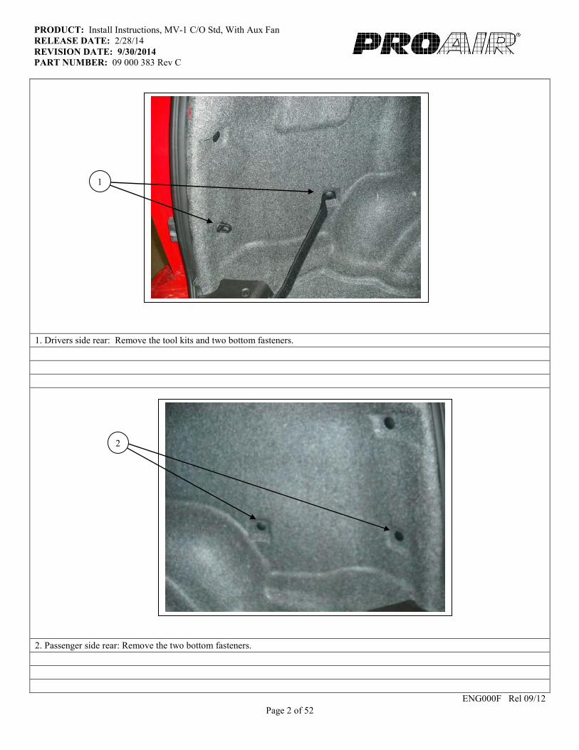
1. Drivers side rear: Remove the tool kits and two bottom fasteners.
2. Passenger side rear: Remove the two bottom fasteners.
ENG000F Rel 09/12
2
1

Page 3 of 52
PRODUCT: Install Instructions, MV-1 C/O Std, With Aux Fan
RELEASE DATE: 2/28/14
REVISION DATE: 9/30/2014 PART NUMBER: 09 000 383 Rev C
3. Install the (2) fasteners from the passenger side; into the driver’s side.
4. Install the fastener with the strap in the hole furthest from the back door on the passenger side. Install the fastener with the loop to
the other hole.
ENG000F Rel 09/12
4
3
Page 4 of 52
PRODUCT: Install Instructions, MV-1 C/O Std, With Aux Fan
RELEASE DATE: 2/28/14
REVISION DATE: 9/30/2014 PART NUMBER: 09 000 383 Rev C
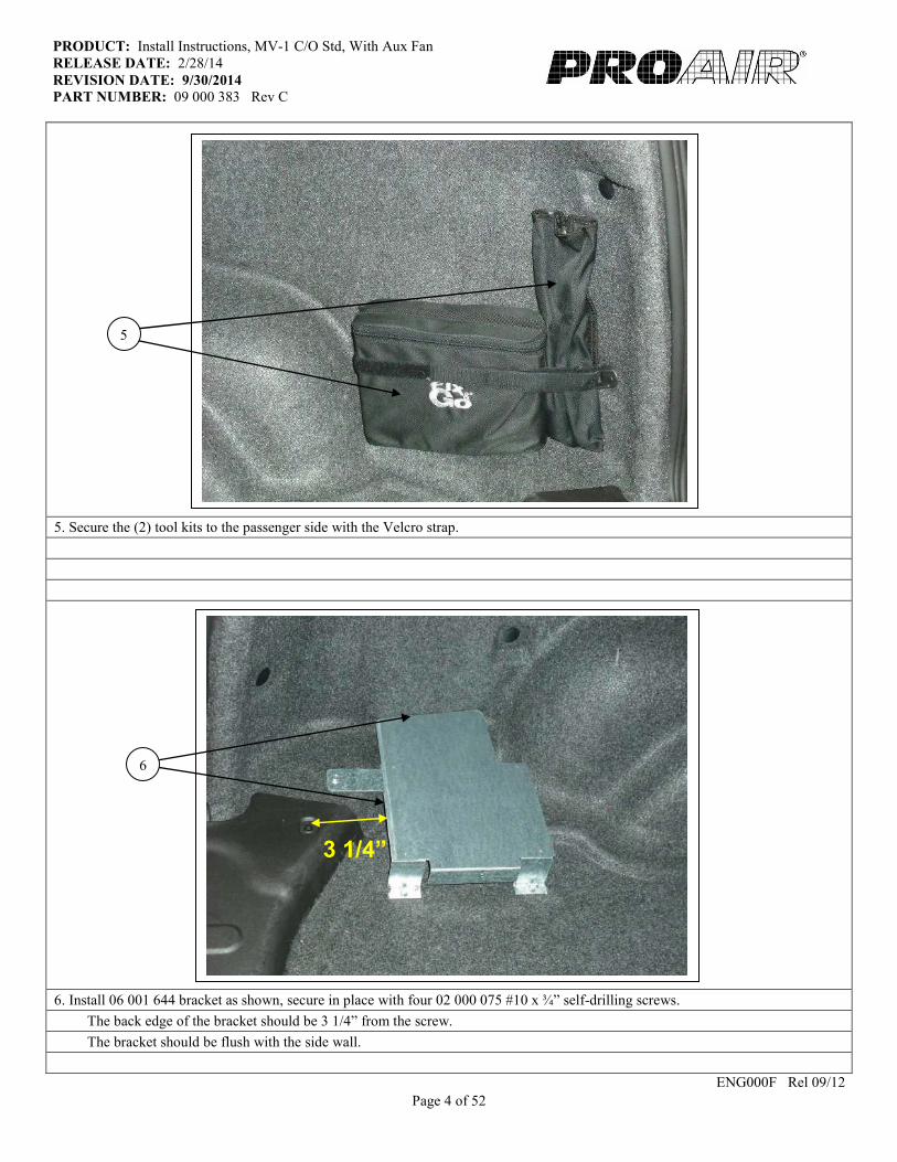
5. Secure the (2) tool kits to the passenger side with the Velcro strap.
6. Install 06 001 644 bracket as shown, secure in place with four 02 000 075 #10 x ¾” self-drilling screws.
The back edge of the bracket should be 3 1/4” from the screw.
The bracket should be flush with the side wall.
ENG000F Rel 09/12
3 1/4”
5
6

Page 5 of 52
PRODUCT: Install Instructions, MV-1 C/O Std, With Aux Fan
RELEASE DATE: 2/28/14
REVISION DATE: 9/30/2014 PART NUMBER: 09 000 383 Rev C
7. Drill a 7/8” hole even with the edge of bracket and on top of hump in carpet.
8. On left side of van, inside just behind rear wheel well right below hump in wall carpet cut out a 6” x 9” hole in sidewall.
ENG000F Rel 09/12
7
8
Page 6 of 52
PRODUCT: Install Instructions, MV-1 C/O Std, With Aux Fan
RELEASE DATE: 2/28/14
REVISION DATE: 9/30/2014 PART NUMBER: 09 000 383 Rev C
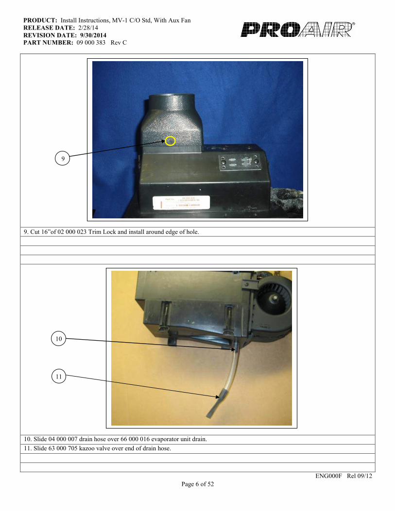
9. Cut 16”of 02 000 023 Trim Lock and install around edge of hole.
10. Slide 04 000 007 drain hose over 66 000 016 evaporator unit drain.
11. Slide 63 000 705 kazoo valve over end of drain hose.
ENG000F Rel 09/12
11
9
10

Page 7 of 52
PRODUCT: Install Instructions, MV-1 C/O Std, With Aux Fan
RELEASE DATE: 2/28/14
REVISION DATE: 9/30/2014 PART NUMBER: 09 000 383 Rev C
12. From underneath van behind left rear wheel remove plug or tape from factory hole.
13. Drill a 1 ¼” hole beside factory hole and apply primer to bare metal.
14. Run the 90 degree fitting on 62 000 944 #6 A/C hose and 01 000 776 harness up the factory hole, grommet, and out hole in
the sidewall.
15. Run 62 000 885 #10 A/C hose up the 1 ¼” hole and out hole in sidewall.
ENG000F Rel 09/12
13
12
15
14
Page 8 of 52
PRODUCT: Install Instructions, MV-1 C/O Std, With Aux Fan
RELEASE DATE: 2/28/14
REVISION DATE: 9/30/2014 PART NUMBER: 09 000 383 Rev C
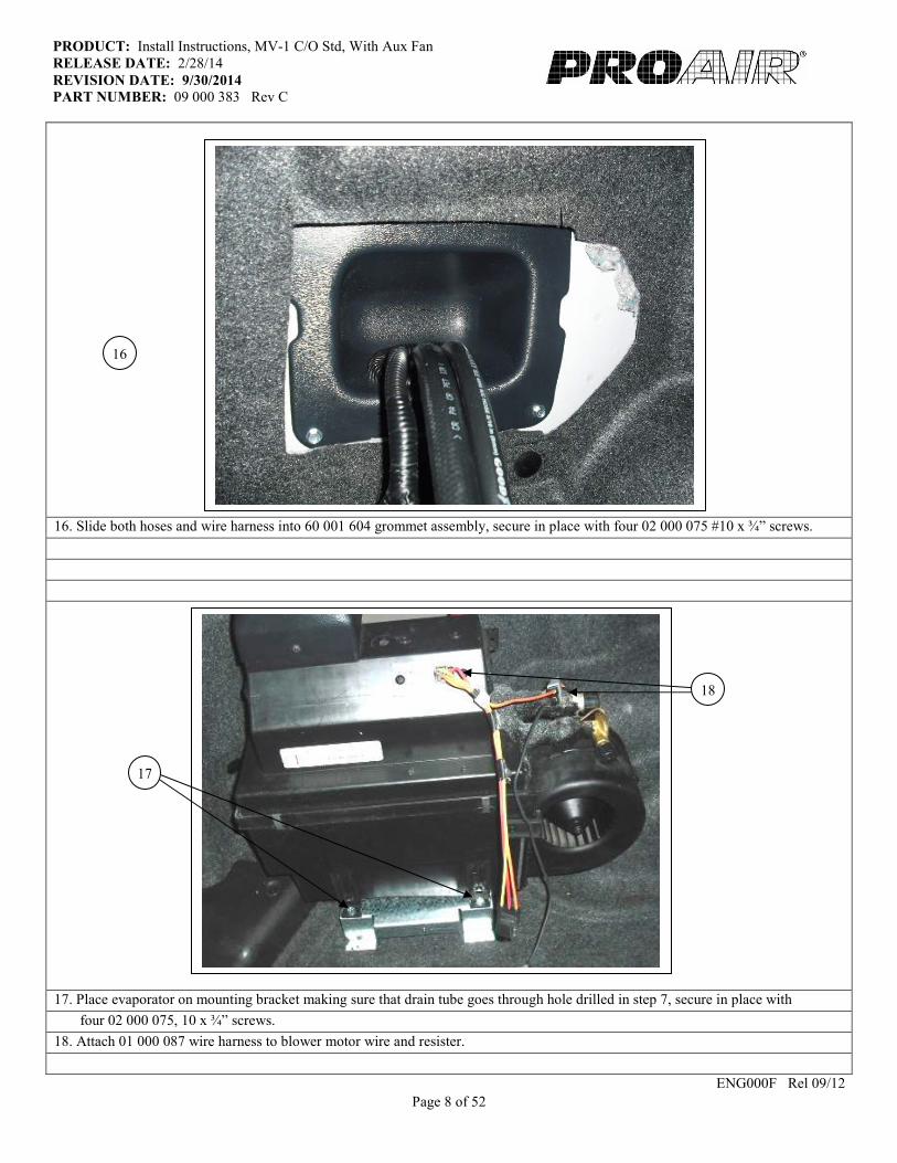
16. Slide both hoses and wire harness into 60 001 604 grommet assembly, secure in place with four 02 000 075 #10 x ¾” screws.
17. Place evaporator on mounting bracket making sure that drain tube goes through hole drilled in step 7, secure in place with
four 02 000 075, 10 x ¾” screws.
18. Attach 01 000 087 wire harness to blower motor wire and resister.
ENG000F Rel 09/12
18
17
16

Page 9 of 52
PRODUCT: Install Instructions, MV-1 C/O CNG, With Aux Fan
RELEASE DATE: 2/28/14
REVISION DATE: 9/30/2014 PART NUMBER: 09 000 383 Rev C
19. Attach 62 000 944 #6 A/C hose to evaporator. Place 08 000 009 #6 o-ring on fitting, apply mineral oil to o-ring and threads
then torque to 11-15 foot pounds.
20. Attach 62 000 885 #10 A/C hose to evaporator. Place 08 000 006 #10 o-ring on fitting apply mineral oil to o-ring
and threads then torque to 21-27 foot pounds.
21. Secure ground wire to inner side wall with 02 000 075 #10 x ¾” screw, place screw in line with spot welds.
ENG000F Rel 09/12
19
21
20
Page 10 of 52
PRODUCT: Install Instructions, MV-1 C/O Std, With Aux Fan
RELEASE DATE: 2/28/14
REVISION DATE: 9/30/2014 PART NUMBER: 09 000 383 Rev C
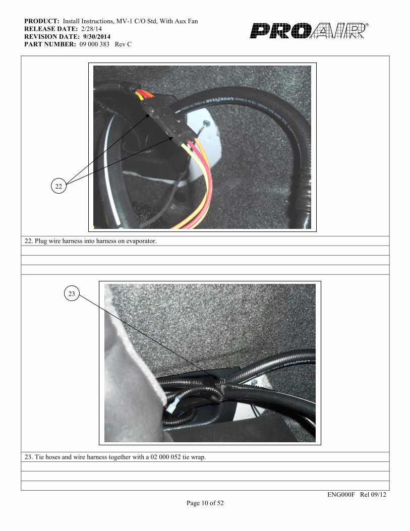
22. Plug wire harness into harness on evaporator.
23. Tie hoses and wire harness together with a 02 000 052 tie wrap.
ENG000F Rel 09/12
23
22

Page 11 of 52
PRODUCT: Install Instructions, MV-1 C/O Std, With Aux Fan
RELEASE DATE: 2/28/14
REVISION DATE: 9/30/2014 PART NUMBER: 09 000 383 Rev C
24. Wrap all of the suction fittings so that no metal is showing and the liquid line needs to be taped up to the disc of expansion valve.
25. Seal hole in plastic hose grommet with silicone as shown
ENG000F Rel 09/12
24
25
Page 12 of 52
PRODUCT: Install Instructions, MV-1 C/O Std, With Aux Fan
RELEASE DATE: 2/28/14
REVISION DATE: 9/30/2014 PART NUMBER: 09 000 383 Rev C
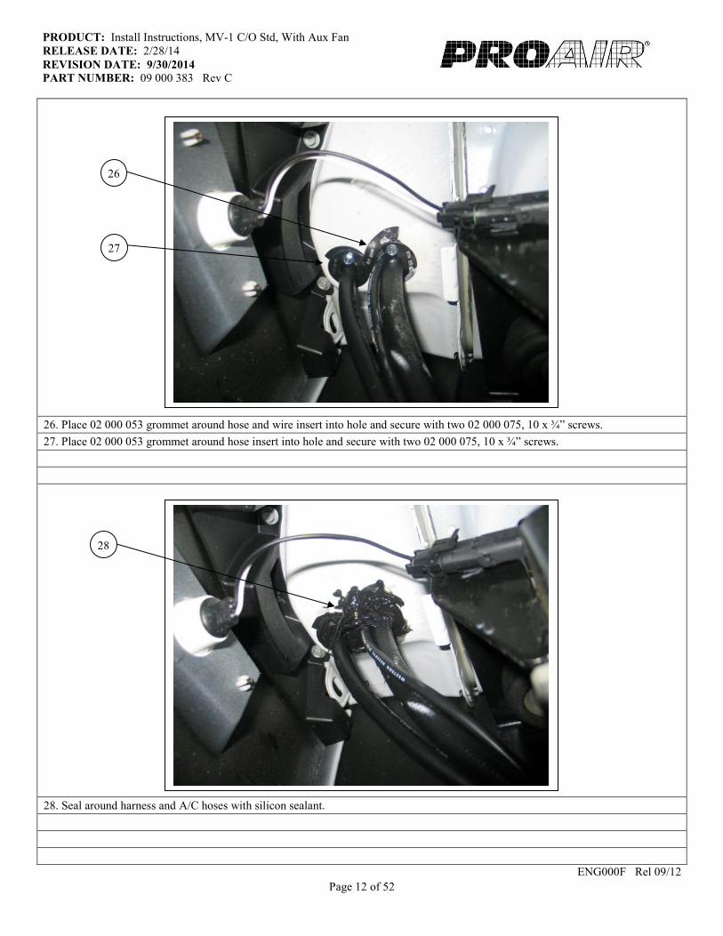
26. Place 02 000 053 grommet around hose and wire insert into hole and secure with two 02 000 075, 10 x ¾” screws.
27. Place 02 000 053 grommet around hose insert into hole and secure with two 02 000 075, 10 x ¾” screws.
28. Seal around harness and A/C hoses with silicon sealant.
ENG000F Rel 09/12
27
26
28
Page 13 of 52
PRODUCT: Install Instructions, MV-1 C/O Std, With Aux Fan
RELEASE DATE: 2/28/14
REVISION DATE: 9/30/2014 PART NUMBER: 09 000 383 Rev C
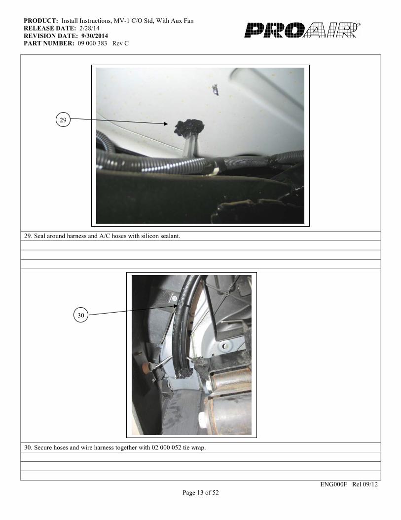
29. Seal around harness and A/C hoses with silicon sealant.
30. Secure hoses and wire harness together with 02 000 052 tie wrap.
ENG000F Rel 09/12
29
30
Page 14 of 52
PRODUCT: Install Instructions, MV-1 C/O Std, With Aux Fan
RELEASE DATE: 2/28/14
REVISION DATE: 9/30/2014 PART NUMBER: 09 000 383 Rev C
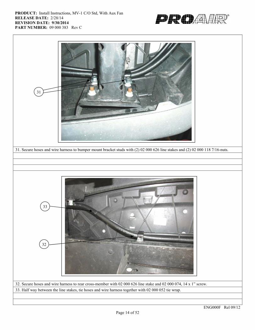
31. Secure hoses and wire harness to bumper mount bracket studs with (2) 02 000 626 line stakes and (2) 02 000 118 7/16-nuts.
32. Secure hoses and wire harness to rear cross-member with 02 000 626 line stake and 02 000 074, 14 x 1” screw.
33. Half way between the line stakes, tie hoses and wire harness together with 02 000 052 tie wrap.
ENG000F Rel 09/12
32
33
31
Page 15 of 52
PRODUCT: Install Instructions, MV-1 C/O Std, With Aux Fan
RELEASE DATE: 2/28/14
REVISION DATE: 9/30/2014 PART NUMBER: 09 000 383 Rev C
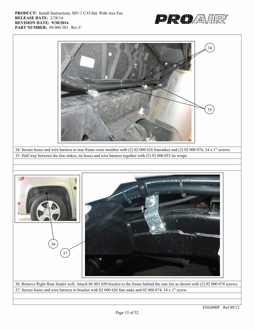
34. Secure hoses and wire harness to rear frame cross member with (2) 02 000 626 linestakes and (2) 02 000 074, 14 x 1” screws.
35. Half way between the line stakes, tie hoses and wire harness together with (2) 02 000 052 tie wraps.
36. Remove Right Rear fender well, Attach 06 001 650 bracket to the frame behind the rear tire as shown with (2) 02 000 074 screws.
37. Secure hoses and wire harness to bracket with 02 000 626 line stake and 02 000 074, 14 x 1” screw.
ENG000F Rel 09/12
34
35
36
37
Page 16 of 52
PRODUCT: Install Instructions, MV-1 C/O Std, With Aux Fan
RELEASE DATE: 2/28/14
REVISION DATE: 9/30/2014 PART NUMBER: 09 000 383 Rev C
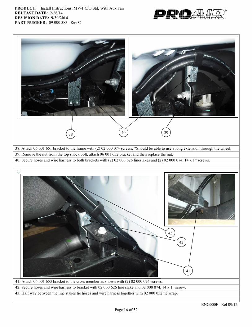
38. Attach 06 001 651 bracket to the frame with (2) 02 000 074 screws. *Should be able to use a long extension through the wheel.
39. Remove the nut from the top shock bolt, attach 06 001 652 bracket and then replace the nut.
40. Secure hoses and wire harness to both brackets with (2) 02 000 626 linestakes and (2) 02 000 074, 14 x 1” screws.
41. Attach 06 001 653 bracket to the cross member as shown with (2) 02 000 074 screws.
42. Secure hoses and wire harness to bracket with 02 000 626 line stake and 02 000 074, 14 x 1” screw.
43. Half way between the line stakes tie hoses and wire harness together with 02 000 052 tie wrap.
ENG000F Rel 09/12
46
38 39
43
40
41
42

Page 17 of 52
PRODUCT: Install Instructions, MV-1 C/O Std, With Aux Fan
RELEASE DATE: 2/28/14
REVISION DATE: 9/30/2014 PART NUMBER: 09 000 383 Rev C
44. Secure hoses and wire harness to frame with (3) 02 000 626 linestakes and (3) 02 000 074, 14 x 1” screws.
45. Half way between the linestakes tie hoses and wire harness together with (3) 02 000 052 tie wraps.
46. Secure hoses and wire harness to the body with (2) 02 000 626 linestakes and (2) 02 000 074, 14 x 1” screws.
47. Half way between the line stakes tie hoses and wire harness together with (2) 02 000 052 tie wraps.
ENG000F Rel 09/12
45
44
46
47

Page 18 of 52
PRODUCT: Install Instructions, MV-1 C/O Std, With Aux Fan
RELEASE DATE: 2/28/14
REVISION DATE: 9/30/2014 PART NUMBER: 09 000 383 Rev C
48. Remove front right fender liner (11) 7mm screws and place 6” of trim lock part number 02 000 023 on body lip above hoses.
trim lock should be visible sides of the hoses.
49. From outside of frame secure hoses and wire harness to body cross member with 02 000 626 line stake and 02 000 074,
14 x 1” screw. *Keep hoses tucked above frame as much as possible to keep them from rubbing on the inner fender well.
50. Half way between the line stakes tie hoses and wire harness together with 02 000 052 tie wrap.
51. Secure hoses and wire harness to the frame with 02 000 626 linestake, 02 000 381 washer, 02 000 074, 14 x 1” screw.
ENG000F Rel 09/12
49
48
50
51
Page 19 of 52
PRODUCT: Install Instructions, MV-1 C/O Std, With Aux Fan
RELEASE DATE: 2/28/14
REVISION DATE: 9/30/2014 PART NUMBER: 09 000 383 Rev C
ENG000F Rel 09/12
Page 20 of 52
PRODUCT: Install Instructions, MV-1 C/O Std, With Aux Fan
RELEASE DATE: 2/28/14
REVISION DATE: 9/30/2014 PART NUMBER: 09 000 383 Rev C
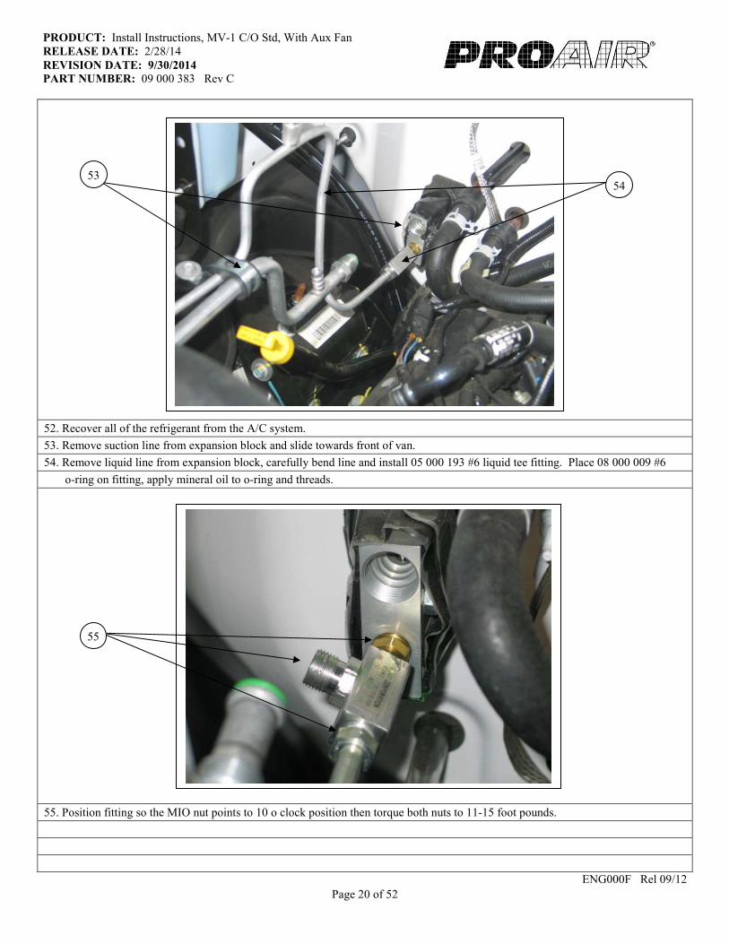
52. Recover all of the refrigerant from the A/C system.
53. Remove suction line from expansion block and slide towards front of van.
54. Remove liquid line from expansion block, carefully bend line and install 05 000 193 #6 liquid tee fitting. Place 08 000 009 #6
o-ring on fitting, apply mineral oil to o-ring and threads.
55. Position fitting so the MIO nut points to 10 o clock position then torque both nuts to 11-15 foot pounds.
ENG000F Rel 09/12
54 53
55
Page 21 of 52
PRODUCT: Install Instructions, MV-1 C/O Std, With Aux Fan
RELEASE DATE: 2/28/14
REVISION DATE: 9/30/2014 PART NUMBER: 09 000 383 Rev C
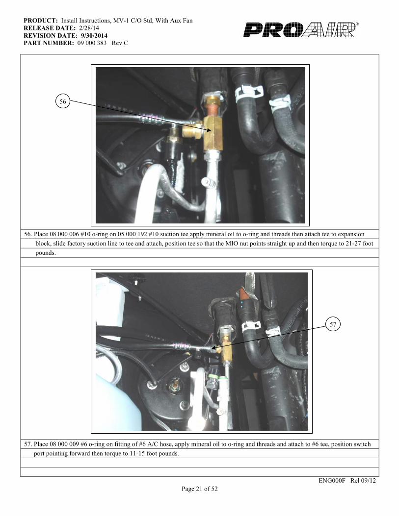
56. Place 08 000 006 #10 o-ring on 05 000 192 #10 suction tee apply mineral oil to o-ring and threads then attach tee to expansion
block, slide factory suction line to tee and attach, position tee so that the MIO nut points straight up and then torque to 21-27 foot
pounds.
57. Place 08 000 009 #6 o-ring on fitting of #6 A/C hose, apply mineral oil to o-ring and threads and attach to #6 tee, position switch
port pointing forward then torque to 11-15 foot pounds.
ENG000F Rel 09/12
56
57
Page 22 of 52
PRODUCT: Install Instructions, MV-1 C/O Std, With Aux Fan
RELEASE DATE: 2/28/14
REVISION DATE: 9/30/2014 PART NUMBER: 09 000 383 Rev C
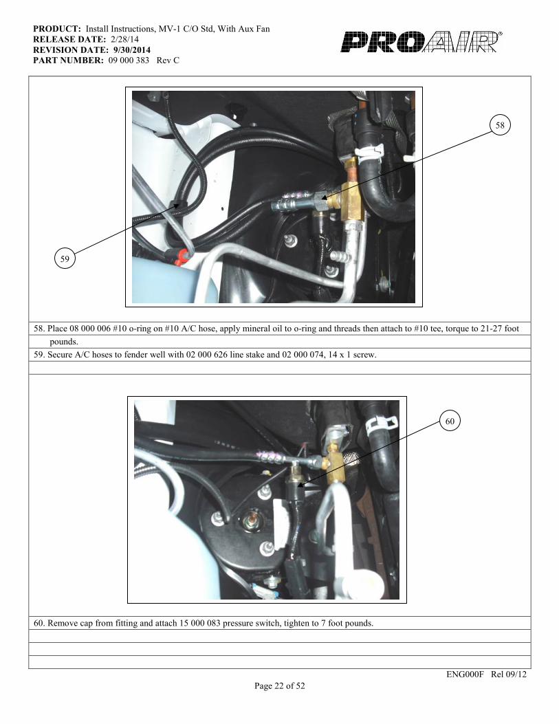
58. Place 08 000 006 #10 o-ring on #10 A/C hose, apply mineral oil to o-ring and threads then attach to #10 tee, torque to 21-27 foot
pounds.
59. Secure A/C hoses to fender well with 02 000 626 line stake and 02 000 074, 14 x 1 screw.
60. Remove cap from fitting and attach 15 000 083 pressure switch, tighten to 7 foot pounds.
ENG000F Rel 09/12
58
59
60
Page 23 of 52
PRODUCT: Install Instructions, MV-1 C/O Std, With Aux Fan
RELEASE DATE: 2/28/14
REVISION DATE: 9/30/2014 PART NUMBER: 09 000 383 Rev C
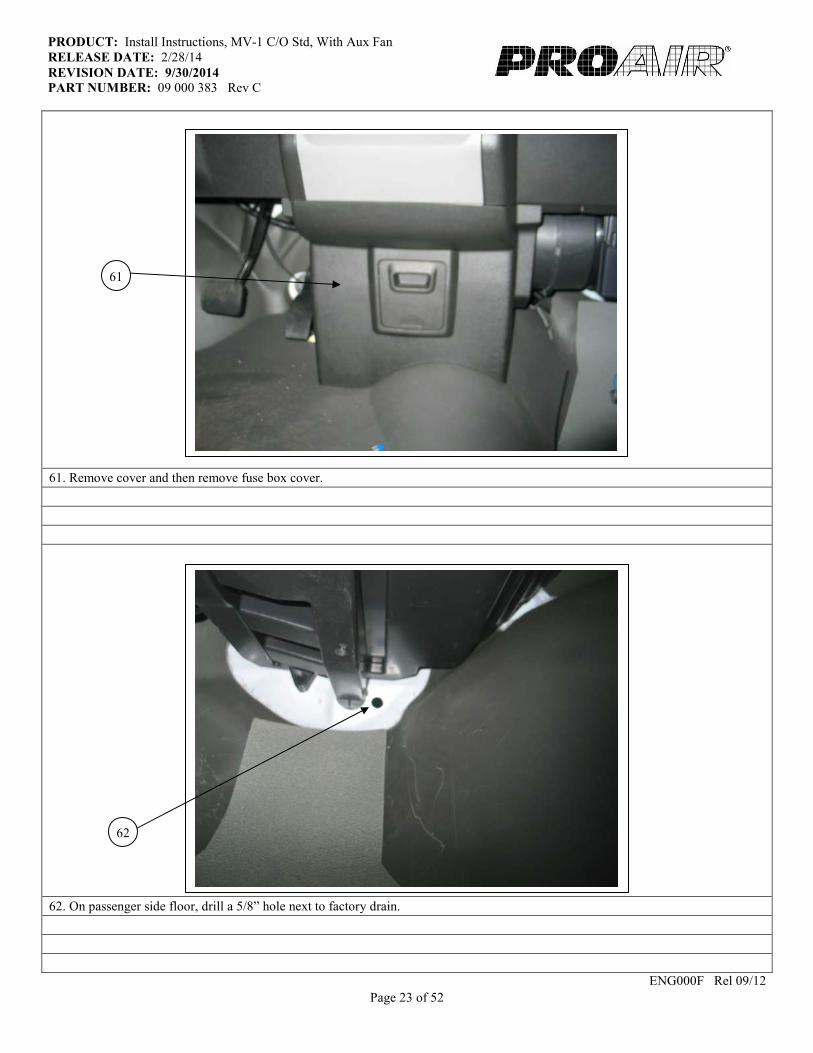
61. Remove cover and then remove fuse box cover.
62. On passenger side floor, drill a 5/8” hole next to factory drain.
ENG000F Rel 09/12
62
61
Page 24 of 52
PRODUCT: Install Instructions, MV-1 C/O Std, With Aux Fan
RELEASE DATE: 2/28/14
REVISION DATE: 9/30/2014 PART NUMBER: 09 000 383 Rev C
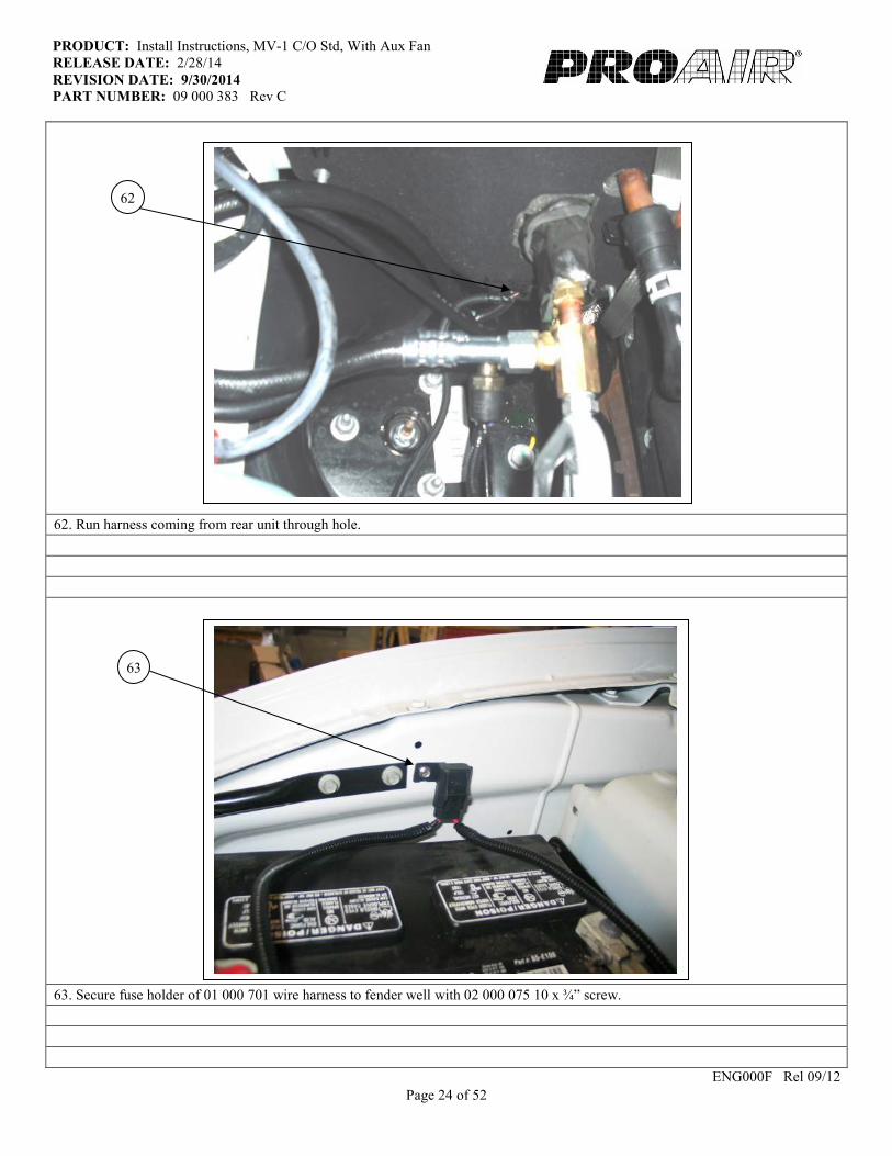
62. Run harness coming from rear unit through hole.
63. Secure fuse holder of 01 000 701 wire harness to fender well with 02 000 075 10 x ¾” screw.
ENG000F Rel 09/12
62
63

Page 25 of 52
PRODUCT: Install Instructions, MV-1 C/O Std, With Aux Fan
RELEASE DATE: 2/28/14
REVISION DATE: 9/30/2014 PART NUMBER: 09 000 383 Rev C
64. Insert long side of harness up to convoluted tubing, into hole drilled in step 65, secure harness with 02 000 052 wire tie.
65. Place 02 000 056 grommet around both harnesses and snap into hole.
ENG000F Rel 09/12
65
64
Page 26 of 52
PRODUCT: Install Instructions, MV-1 C/O Std, With Aux Fan
RELEASE DATE: 2/28/14
REVISION DATE: 9/30/2014 PART NUMBER: 09 000 383 Rev C
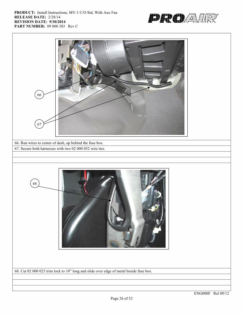
66. Run wires to center of dash, up behind the fuse box.
67. Secure both harnesses with two 02 000 052 wire ties.
68. Cut 02 000 023 trim lock to 10” long and slide over edge of metal beside fuse box.
ENG000F Rel 09/12
66
68
67
Page 27 of 52
PRODUCT: Install Instructions, MV-1 C/O Std, With Aux Fan
RELEASE DATE: 2/28/14
REVISION DATE: 9/30/2014 PART NUMBER: 09 000 383 Rev C
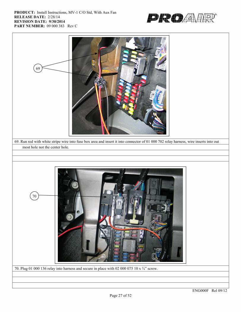
69. Run red with white stripe wire into fuse box area and insert it into connector of 01 000 702 relay harness, wire inserts into out
most hole not the center hole.
70. Plug 01 000 136 relay into harness and secure in place with 02 000 075 10 x ¾” screw.
ENG000F Rel 09/12
70
69
Page 28 of 52
PRODUCT: Install Instructions, MV-1 C/O Std, With Aux Fan
RELEASE DATE: 2/28/14
REVISION DATE: 9/30/2014 PART NUMBER: 09 000 383 Rev C
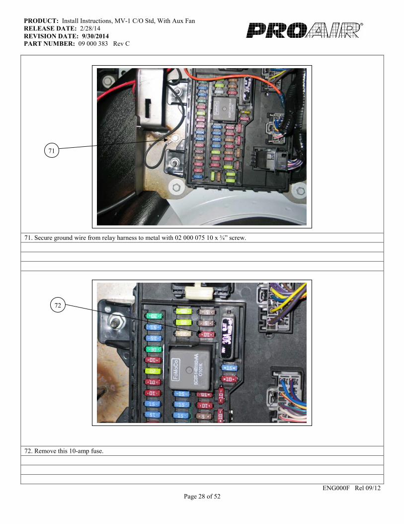
71. Secure ground wire from relay harness to metal with 02 000 075 10 x ¾” screw.
72. Remove this 10-amp fuse.
ENG000F Rel 09/12
71
72
Page 29 of 52
PRODUCT: Install Instructions, MV-1 C/O Std, With Aux Fan
RELEASE DATE: 2/28/14
REVISION DATE: 9/30/2014 PART NUMBER: 09 000 383 Rev C
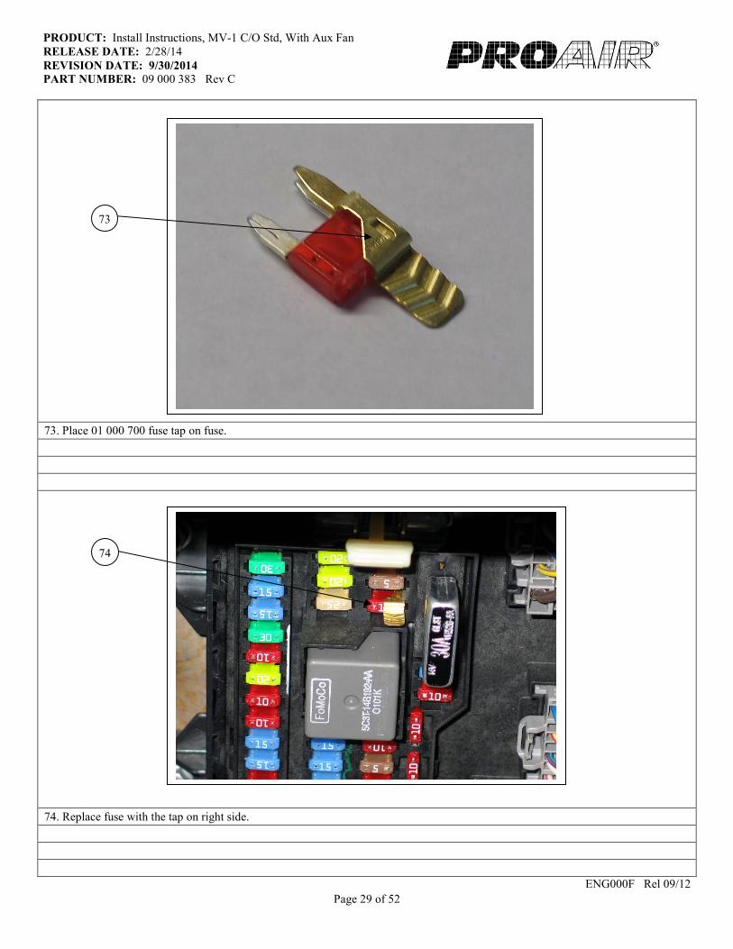
73. Place 01 000 700 fuse tap on fuse.
74. Replace fuse with the tap on right side.
ENG000F Rel 09/12
73
74
Page 30 of 52
PRODUCT: Install Instructions, MV-1 C/O Std, With Aux Fan
RELEASE DATE: 2/28/14
REVISION DATE: 9/30/2014 PART NUMBER: 09 000 383 Rev C
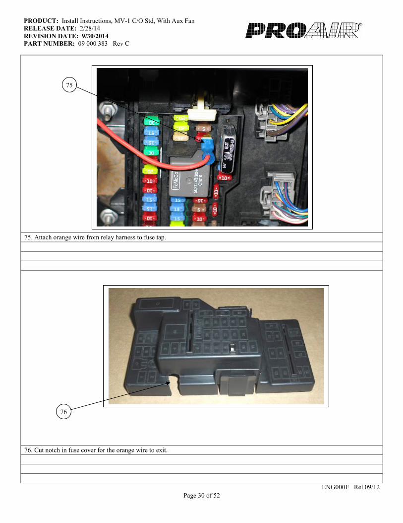
75. Attach orange wire from relay harness to fuse tap.
76. Cut notch in fuse cover for the orange wire to exit.
ENG000F Rel 09/12
75
76
Page 31 of 52
PRODUCT: Install Instructions, MV-1 C/O Std, With Aux Fan
RELEASE DATE: 2/28/14
REVISION DATE: 9/30/2014 PART NUMBER: 09 000 383 Rev C
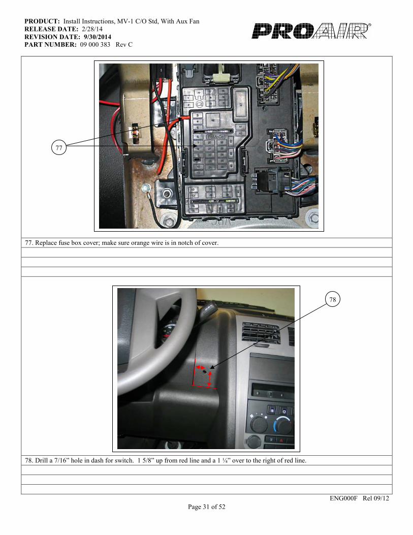
77. Replace fuse box cover; make sure orange wire is in notch of cover.
78. Drill a 7/16” hole in dash for switch. 1 5/8” up from red line and a 1 ¼” over to the right of red line.
ENG000F Rel 09/12
78
77
Page 32 of 52
PRODUCT: Install Instructions, MV-1 C/O Std, With Aux Fan
RELEASE DATE: 2/28/14
REVISION DATE: 9/30/2014 PART NUMBER: 09 000 383 Rev C
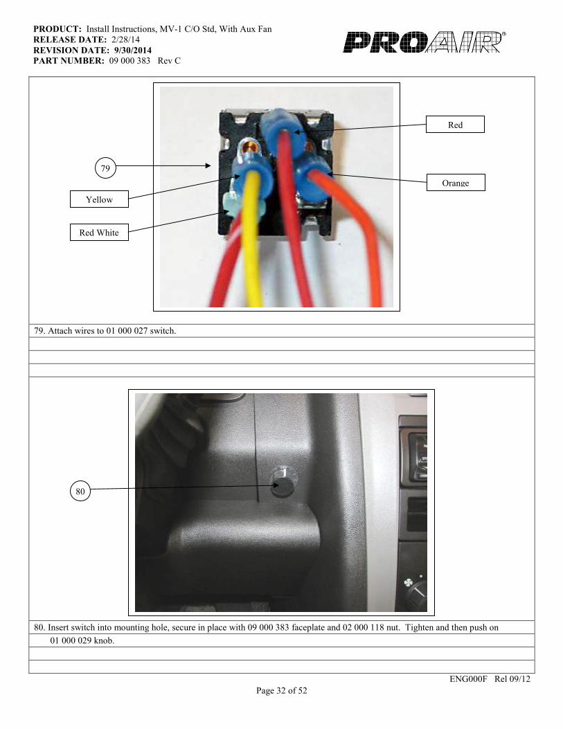
79. Attach wires to 01 000 027 switch.
80. Insert switch into mounting hole, secure in place with 09 000 383 faceplate and 02 000 118 nut. Tighten and then push on
01 000 029 knob.
ENG000F Rel 09/12
79
80
Red White
Yellow
Orange
Red
Page 33 of 52
PRODUCT: Install Instructions, MV-1 C/O Std, With Aux Fan
RELEASE DATE: 2/28/14
REVISION DATE: 9/30/2014 PART NUMBER: 09 000 383 Rev C
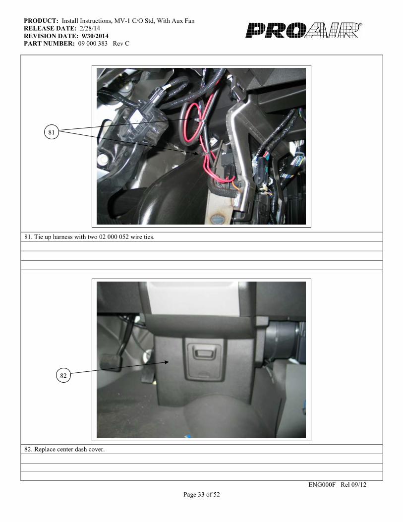
81. Tie up harness with two 02 000 052 wire ties.
82. Replace center dash cover.
ENG000F Rel 09/12
81
82

Page 34 of 52
Page 35 of 52
PRODUCT: Install Instructions, MV-1 C/O Std, With Aux Fan
RELEASE DATE: 2/28/14
REVISION DATE: 9/30/2014 PART NUMBER: 09 000 383 Rev C
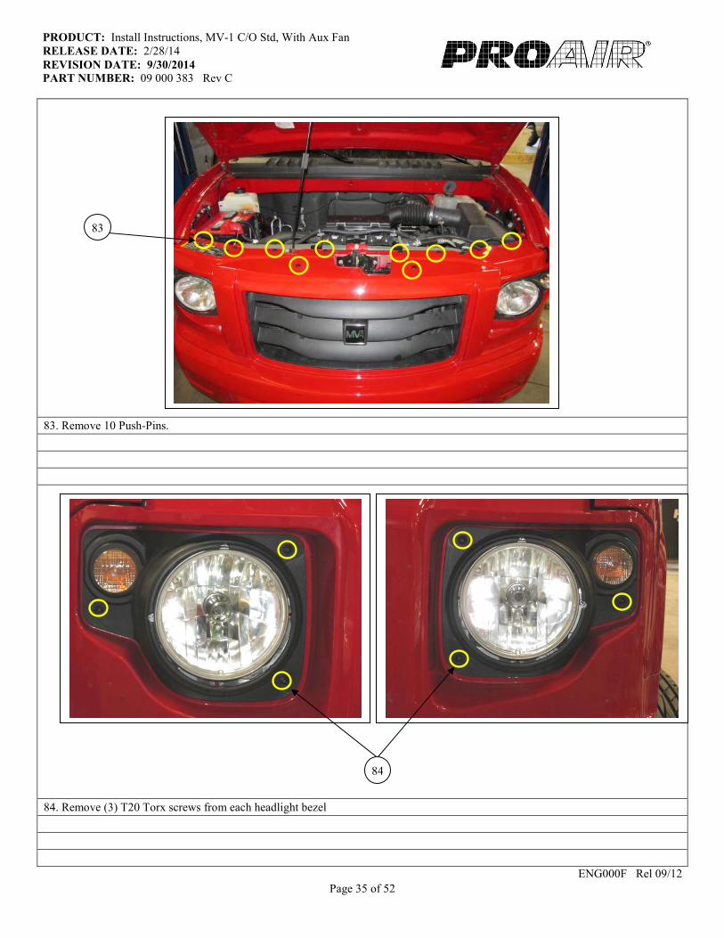
83. Remove 10 Push-Pins.
84. Remove (3) T20 Torx screws from each headlight bezel
ENG000F Rel 09/12
83
84
Page 36 of 52
PRODUCT: Install Instructions, MV-1 C/O Std, With Aux Fan
RELEASE DATE: 2/28/14
REVISION DATE: 9/30/2014 PART NUMBER: 09 000 383 Rev C
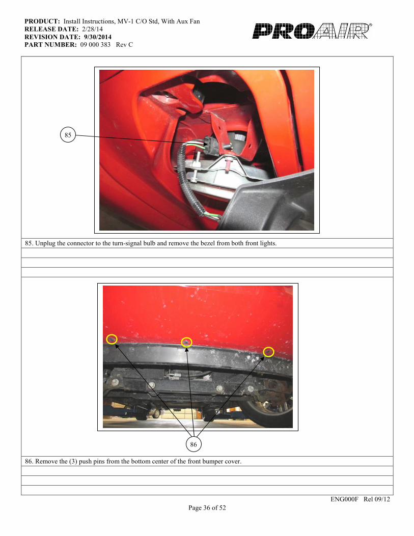
85. Unplug the connector to the turn-signal bulb and remove the bezel from both front lights.
86. Remove the (3) push pins from the bottom center of the front bumper cover.
ENG000F Rel 09/12
85
86
Page 37 of 52
PRODUCT: Install Instructions, MV-1 C/O Std, With Aux Fan
RELEASE DATE: 2/28/14
REVISION DATE: 9/30/2014 PART NUMBER: 09 000 383 Rev C
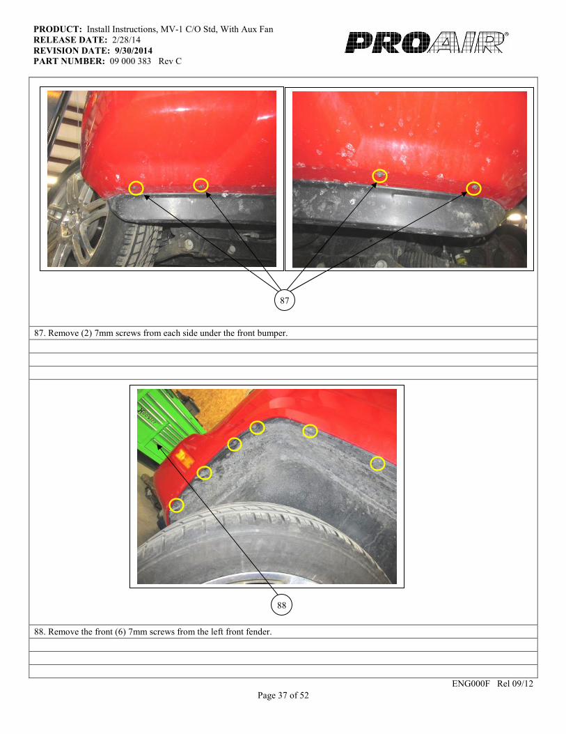
87. Remove (2) 7mm screws from each side under the front bumper.
88. Remove the front (6) 7mm screws from the left front fender.
ENG000F Rel 09/12
87
88

Page 38 of 52
PRODUCT: Install Instructions, MV-1 C/O Std, With Aux Fan
RELEASE DATE: 2/28/14
REVISION DATE: 9/30/2014 PART NUMBER: 09 000 383 Rev C
89. (Looking up into the fender) Remove (2) 10mm bolts that secure the front bumper cover to the fender, on each side of the vehicle.
90. (Looking up, at the back-side of the headlight assembly) Remove the nut from the stud with a 7mm socket
ENG000F Rel 09/12
90
89

Page 39 of 52
PRODUCT: Install Instructions, MV-1 C/O Std, With Aux Fan
RELEASE DATE: 2/28/14
REVISION DATE: 9/30/2014 PART NUMBER: 09 000 383 Rev C
91. Unplug the turn-signal / parking-light connector on each side of the bumper cover.
92. Have a 2nd person assist removing the front cover. (May require some maneuvering / wiggling to get the top two 7mm studs out.)
93. Remove (3) bolts with a 13mm socket.
94. Trim the off the plastic tabs at the yellow marks.
ENG000F Rel 09/12
94
91
92
93
Page 40 of 52
PRODUCT: Install Instructions, MV-1 C/O Std, With Aux Fan
RELEASE DATE: 2/28/14
REVISION DATE: 9/30/2014 PART NUMBER: 09 000 383 Rev C
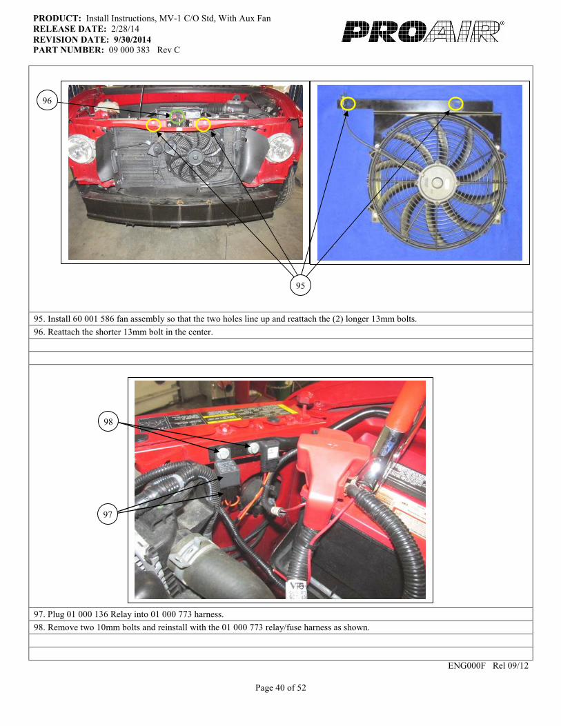
95. Install 60 001 586 fan assembly so that the two holes line up and reattach the (2) longer 13mm bolts.
96. Reattach the shorter 13mm bolt in the center.
97. Plug 01 000 136 Relay into 01 000 773 harness.
98. Remove two 10mm bolts and reinstall with the 01 000 773 relay/fuse harness as shown.
ENG000F Rel 09/12
95
96
98
97
Page 41 of 52
PRODUCT: Install Instructions, MV-1 C/O Std, With Aux Fan
RELEASE DATE: 2/28/14
REVISION DATE: 9/30/2014 PART NUMBER: 09 000 383 Rev C
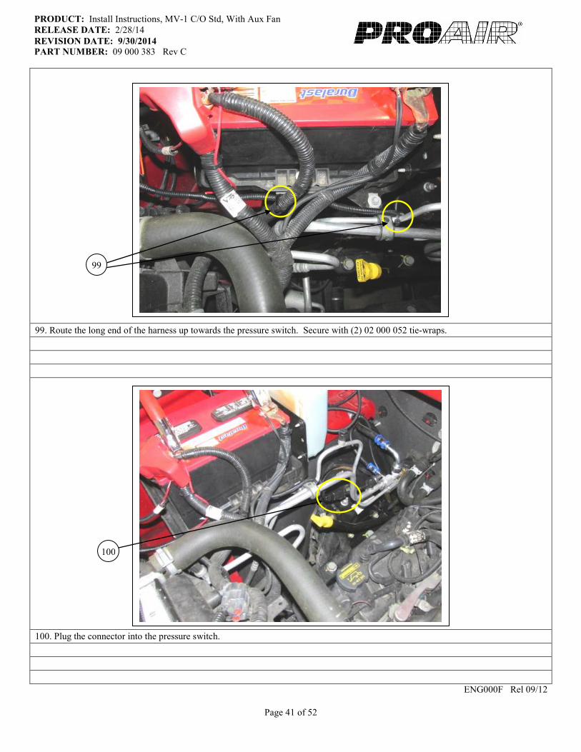
99. Route the long end of the harness up towards the pressure switch. Secure with (2) 02 000 052 tie-wraps.
100. Plug the connector into the pressure switch.
ENG000F Rel 09/12
99
100

Page 42 of 52
PRODUCT: Install Instructions, MV-1 C/O Std, With Aux Fan
RELEASE DATE: 2/28/14
REVISION DATE: 9/30/2014 PART NUMBER: 09 000 383 Rev C
101. Run the other end of the harness under the foam in the top corner by the condenser coil. Secure with (1) 02 000 052 tie-wrap.
102. Route the harness/connector as shown and plug into the fan. Secure with (1) 02 000 052 tie-wrap.
ENG000F Rel 09/12
101
102
Page 43 of 52
PRODUCT: Install Instructions, MV-1 C/O Std, With Aux Fan
RELEASE DATE: 2/28/14
REVISION DATE: 9/30/2014 PART NUMBER: 09 000 383 Rev C
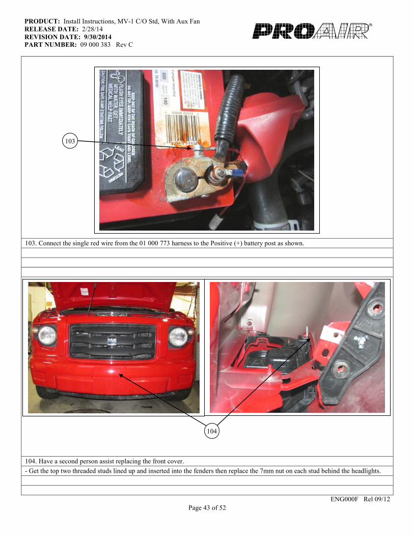
103. Connect the single red wire from the 01 000 773 harness to the Positive (+) battery post as shown.
104. Have a second person assist replacing the front cover.
- Get the top two threaded studs lined up and inserted into the fenders then replace the 7mm nut on each stud behind the headlights.
ENG000F Rel 09/12
104
103

Page 44 of 52
PRODUCT: Install Instructions, MV-1 C/O Std, With Aux Fan
RELEASE DATE: 2/28/14
REVISION DATE: 9/30/2014 PART NUMBER: 09 000 383 Rev C
105. Replace the (2) 10mm bolts inside each fender.
106. Reconnect the side-marker light plug on the bumper (both sides).
ENG000F Rel 09/12
106
105

Page 45 of 52
PRODUCT: Install Instructions, MV-1 C/O Std, With Aux Fan
RELEASE DATE: 2/28/14
REVISION DATE: 9/30/2014 PART NUMBER: 09 000 383 Rev C
107. Replace (2) 7mm screws on each side, under the front bumper.
108. Replace (3) push pins in the center under the front bumper.
ENG000F Rel 09/12
107
108
Page 46 of 52
PRODUCT: Install Instructions, MV-1 C/O Std, With Aux Fan
RELEASE DATE: 2/28/14
REVISION DATE: 9/30/2014 PART NUMBER: 09 000 383 Rev C
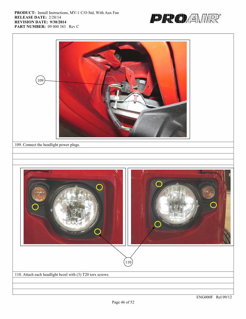
109. Connect the headlight power plugs.
110. Attach each headlight bezel with (3) T20 torx screws.
ENG000F Rel 09/12
109
110
Page 47 of 52
PRODUCT: Install Instructions, MV-1 C/O Std, With Aux Fan
RELEASE DATE: 2/28/14
REVISION DATE: 9/30/2014 PART NUMBER: 09 000 383 Rev C
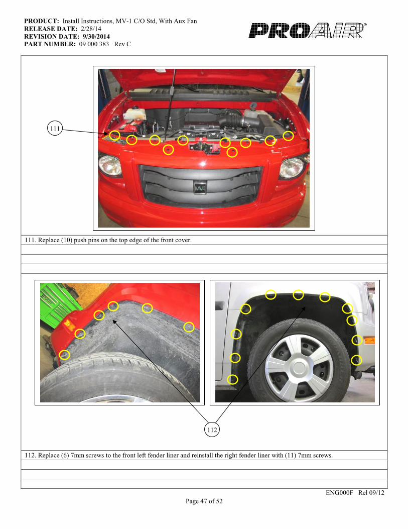
111. Replace (10) push pins on the top edge of the front cover.
112. Replace (6) 7mm screws to the front left fender liner and reinstall the right fender liner with (11) 7mm screws.
ENG000F Rel 09/12
111
112
Page 48 of 52
PRODUCT: Install Instructions, MV-1 C/O Std, With Aux Fan
RELEASE DATE: 2/28/14
REVISION DATE: 9/30/2014 PART NUMBER: 09 000 383 Rev C
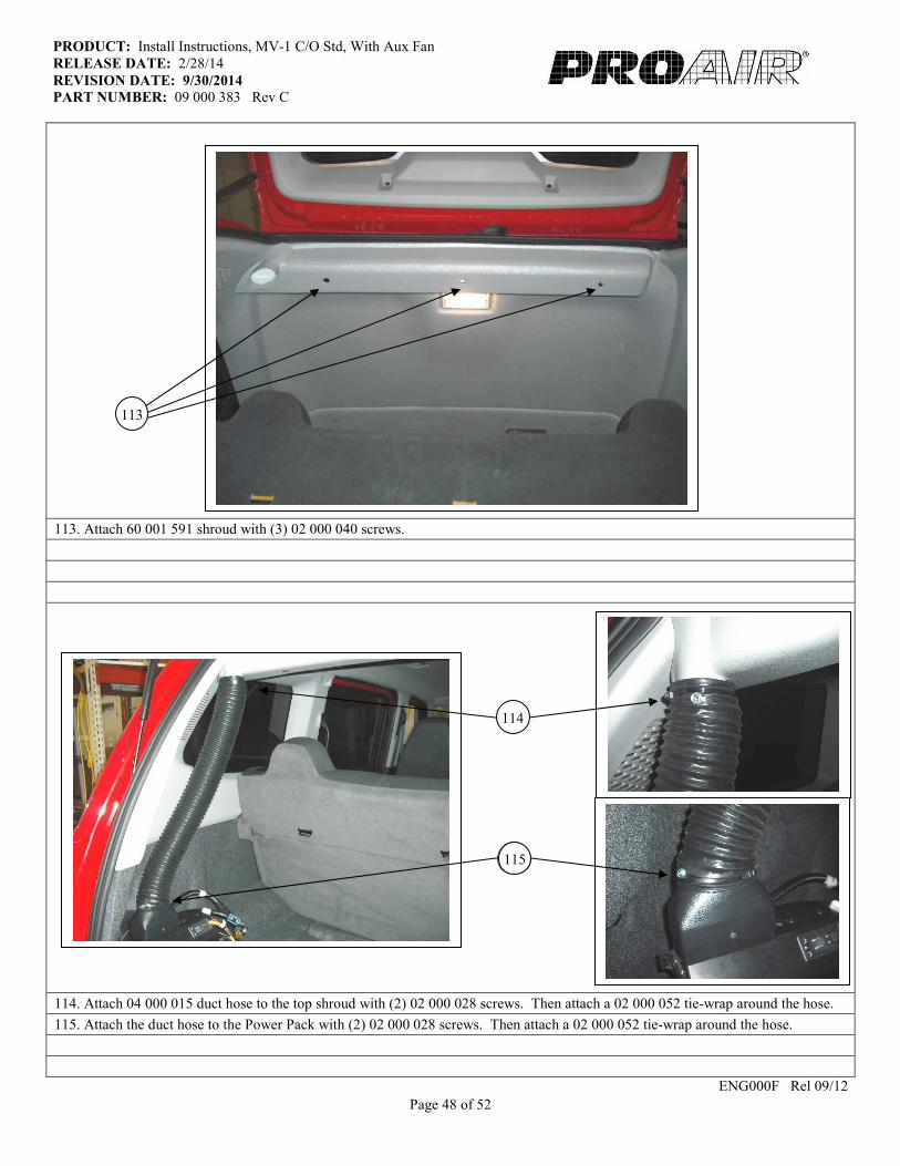
113. Attach 60 001 591 shroud with (3) 02 000 040 screws.
114. Attach 04 000 015 duct hose to the top shroud with (2) 02 000 028 screws. Then attach a 02 000 052 tie-wrap around the hose.
115. Attach the duct hose to the Power Pack with (2) 02 000 028 screws. Then attach a 02 000 052 tie-wrap around the hose.
ENG000F Rel 09/12
119
113
114
115

Page 49 of 52
PRODUCT: Install Instructions, MV-1 C/O Std, With Aux Fan
RELEASE DATE: 2/28/14
REVISION DATE: 9/30/2014 PART NUMBER: 09 000 383 Rev C
116. Wrap 08 000 001 foam tape around unit outlet and duct hose to seal connections.
117. Set 60 001 589 Cover Assy. over the Power Pack. Do not attach it yet.
ENG000F Rel 09/12
117
116
Page 50 of 52
PRODUCT: Install Instructions, MV-1 C/O Std, With Aux Fan
RELEASE DATE: 2/28/14
REVISION DATE: 9/30/2014 PART NUMBER: 09 000 383 Rev C
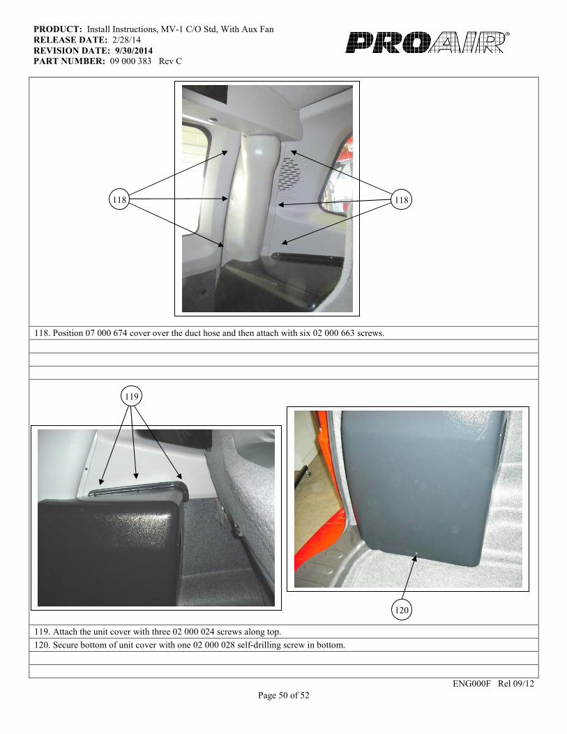
118. Position 07 000 674 cover over the duct hose and then attach with six 02 000 663 screws.
119. Attach the unit cover with three 02 000 024 screws along top.
120. Secure bottom of unit cover with one 02 000 028 self-drilling screw in bottom.
ENG000F Rel 09/12
118 118
119
120

Page 51 of 52
PRODUCT: Install Instructions, MV-1 C/O Std, With Aux Fan
RELEASE DATE: 2/28/14
REVISION DATE: 9/30/2014 PART NUMBER: 09 000 383 Rev C
121. Put (3) 02 000 400 plugs in the holes on the top shroud.
122. Attach power wire to positive battery cable.
ENG000F Rel 09/12
122
121
Page 52 of 52
PRODUCT: Install Instructions, MV-1 C/O Std, With Aux Fan
RELEASE DATE: 2/28/14
REVISION DATE: 9/30/2014 PART NUMBER: 09 000 383 Rev C
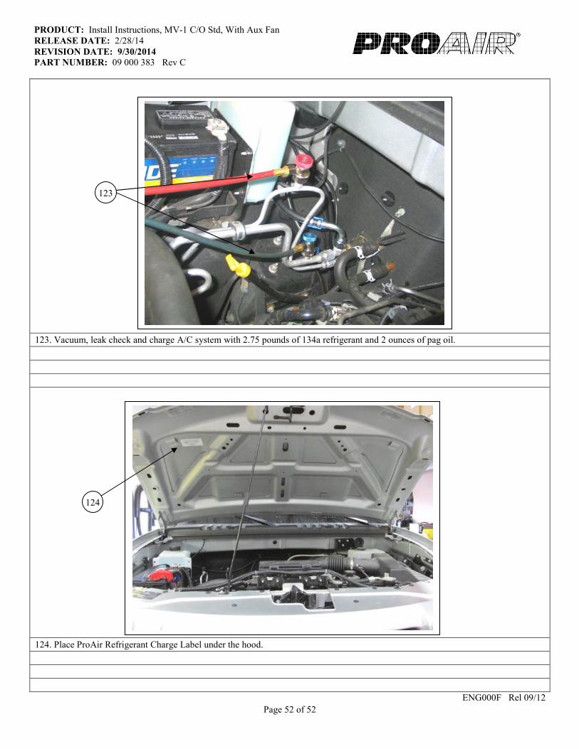
123. Vacuum, leak check and charge A/C system with 2.75 pounds of 134a refrigerant and 2 ounces of pag oil.
124. Place ProAir Refrigerant Charge Label under the hood.
ENG000F Rel 09/12
123
124