1 cse370, lecture 14 lecture 14 u logistics n midterm 1: average 90/100. well done! n midterm...
TRANSCRIPT
1CSE370, Lecture 14
Lecture 14
Logistics Midterm 1: Average 90/100. Well done! Midterm solutions online HW5 due date delayed until this Friday
Last lecture Finished combinational logic Introduction to sequential logic and systems
Today Memory storage elements
Latches Flip-flops
State Diagrams
2CSE370, Lecture 14
Example from last time
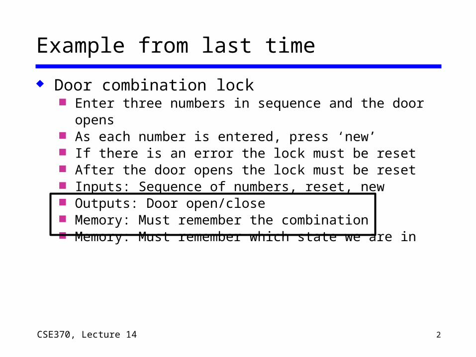
Door combination lock Enter three numbers in sequence and the door opens As each number is entered, press ‘new’ If there is an error the lock must be reset After the door opens the lock must be reset Inputs: Sequence of numbers, reset, new Outputs: Door open/close Memory: Must remember the combination Memory: Must remember which state we are in

3CSE370, Lecture 14
The “WHY” slide
Memory storage elements In order to do fun problems like the door combination
lock, we must know the building blocks (like how you had to learn AND and OR before you could do functional things). Be patient --- once you know these elements, you can build a lot of meaningful functions
State diagrams For combinational logic, truth table was an invaluable
visualization tool for a function. For sequential logic, state diagram serves as a way to visualize a function.

4CSE370, Lecture 14
How do we store info? Feedback
Two inverters can hold a bit As long as power is applied
Storing a new memory Temporarily break the feedback path
"0"
"1"
"stored bit"
"remember"
"load""data" "stored bit"

5CSE370, Lecture 14
The SR latch
Cross-coupled NOR gates Can set (S=1, R=0) or reset (R=1, S=0) the output
R Q
QS
Reset
Set
S R Q0 0 hold0 1 01 0 11 1 disallow

6CSE370, Lecture 14
SR latch behavior
Truth table and timing
Reset Hold Set SetReset Race
R
S
Q
Q'
100
R
S
Q
Q'
S R Q0 0 hold0 1 01 0 11 1 disallow
NOR output is 1 Only when both inputs are 0

7CSE370, Lecture 14
SR latch is glitch sensitive
Static 0 hazards can set/reset latch Glitch on S input sets latch Glitch on R input resets latch
R
S
Q
Q'
0
0

8CSE370, Lecture 14
State diagrams
How do we characterize logic circuits? Combinational circuits: Truth tables Sequential circuits: State diagrams
First draw the states States Unique circuit configurations
Second draw the transitions between states Transitions Changes in state caused by inputs

9CSE370, Lecture 14
Example: SR latch
Begin by drawing the states States Unique circuit
configurations Possible values for feedback (Q, Q')
R
S
Q
Q'
possible oscillationbetween states 00 and 11(when SR=00)
Q Q'0 1
Q Q'1 0
Q Q'0 0
Q Q'1 1
SR=00SR=11
SR=00
SR=10
SR=01
SR=00SR=10
SR=00SR=01
SR=11 SR=11
SR=10SR=01
SR=01 SR=10SR=11
S R Q0 0 hold0 1 01 0 11 1 disallow

10CSE370, Lecture 14
Observed SR latch behavior
The 1–1 state is transitory Either R or S “gets ahead” Latch settles to 0–1 or 1–0 state ambiguously Race condition non-deterministic transition
Disallow (R,S) = (1,1)
R
S
Q
Q'
SR=00SR=10Q Q'
0 1Q Q'1 0
SR=10
SR=01
SR=00SR=01

11CSE370, Lecture 14
The D latch: store it and look it up
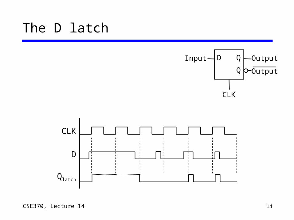
Output depends on clock Clock high: Input passes to
output Clock low: Latch holds its
output
Latches are level sensitive and “transparent”
D Q
Q
CLK
Input Output
Output
CLK
D
Qlatch

12CSE370, Lecture 14
The D flip-flop
Input sampled at clock edge Rising edge: Input passes to output Otherwise: Flip-flop holds its output
Flip-flops can be rising-edge triggered or falling-edge triggered
D Q
Q
CLK
Input Output
Output
CLK
D
Qff

13CSE370, Lecture 14
The D flip-flop
D Q
Q
CLK
Input Output
Output
CLK
D
Qff
14CSE370, Lecture 14
The D latch
D Q
Q
CLK
Input Output
Output
CLK
D
Qlatch

15CSE370, Lecture 14
How do we make a D flip flop?
Edge triggering is difficult You can do this at home:
Label the internal nodes Draw a timing diagram Start with Clk=1
Q
D
Clk
W
Y
X
Z
Q’
16CSE370, Lecture 14
How do we make a D flip flop?
Q
D
Clk
W
Y
X
Z
Q’
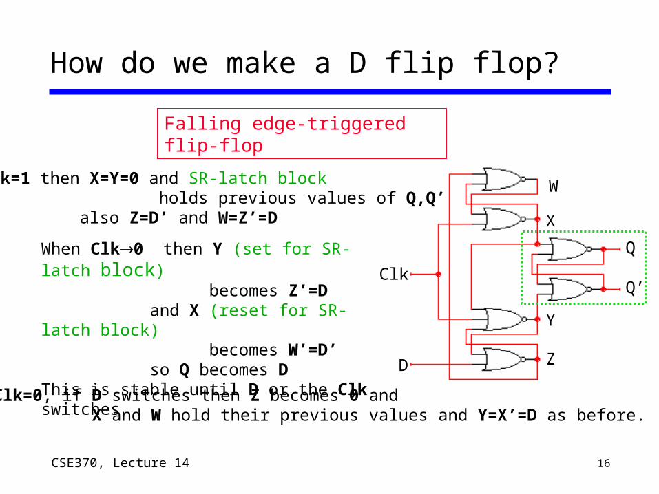
When Clk0 then Y (set for SR-latch block) becomes Z’=D and X (reset for SR-latch block) becomes W’=D’ so Q becomes DThis is stable until D or the Clk switches
If Clk=1 then X=Y=0 and SR-latch block holds previous values of Q,Q’ also Z=D’ and W=Z’=D
While Clk=0, if D switches then Z becomes 0 and X and W hold their previous values and Y=X’=D as before.
Falling edge-triggered flip-flop
17CSE370, Lecture 14
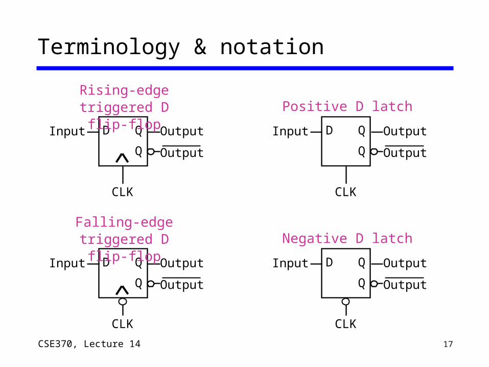
Terminology & notation
D Q
Q
CLK
Input Output
Output
Falling-edge triggered D flip-flop
D Q
Q
CLK
Input Output
Output
Rising-edge triggered D flip-flop
D Q
Q
CLK
Input Output
Output
Negative D latch
D Q
Q
CLK
Input Output
Output
Positive D latch
18CSE370, Lecture 14
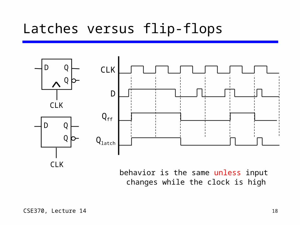
behavior is the same unless input changes while the clock is high
CLK
D
Qff
Qlatch
Latches versus flip-flops
D Q
Q
CLK
D Q
Q
CLK
19CSE370, Lecture 14
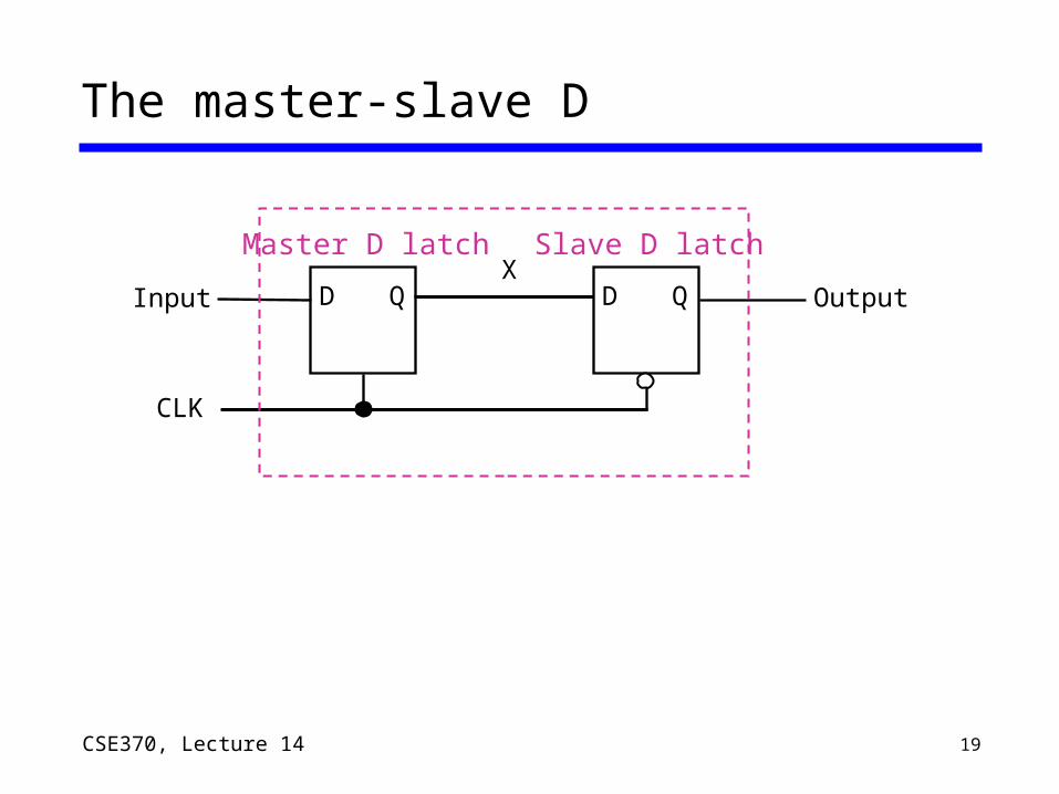
The master-slave D
D Q
CLK
Input
Master D latch
D Q Output
Slave D latchX
20CSE370, Lecture 14
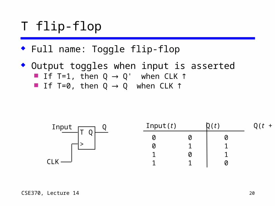
T flip-flop
Full name: Toggle flip-flop
Output toggles when input is asserted If T=1, then Q Q' when CLK If T=0, then Q Q when CLK
CLK
QT Q
>
Input(t) Q(t) Q(t + t)
0 0 00 1 11 0 11 1 0
Input
21CSE370, Lecture 14
Clear and preset in flip-flops
Clear and Preset set flip-flop to a known state Used at startup, reset
Clear or Reset to a logic 0 Synchronous: Q=0 when next clock edge arrives Asynchronous: Q=0 when reset is asserted
Doesn't wait for clock Quick but dangerous
Preset or Set the state to logic 1 Synchronous: Q=1 when next clock edge arrives Asynchronous: Q=1 when reset is asserted
Doesn't wait for clock Quick but dangerous