1 dan o. popa, ee 1205 intro. to ee 1 systems concepts dan popa, ph.d., associate professor...
Post on 20-Dec-2015
241 views
TRANSCRIPT
1Dan O. Popa, EE 1205 Intro. to EE 1
Systems Concepts
Dan Popa, Ph.D., Associate [email protected], http://ngs.uta.edu
• Systems Approach and Related Concepts• Modeling: Physical, mathematical • System identification, block diagrams, subsystems, modules,
interconnection• Input/output, environmental effects, linear-nonlinear, dynamic,
causal-noncausal• Examples of complex robotic systems

2Dan O. Popa, EE 1205 Intro. to EE 2
Signals and Systems
– Signal: • Any time dependent physical quantity• Electrical, Optical, Mechancal
– System:• Object in which input signals interact to
produce output signals.• Some have fundamental properties that make
it predictable: – Sinusoid in, sinusoid out of same frequency (when
transients settle)– Double the amplitude in, double the amplitude out
(when initial state conditions are zero)?
x(t)
u(t) y(t)
3Dan O. Popa, EE 1205 Intro. to EE 3
Signal Classification
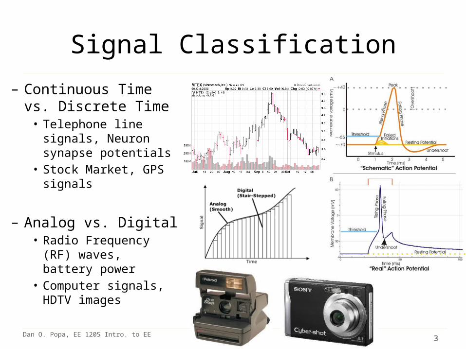
– Continuous Time vs. Discrete Time
• Telephone line signals, Neuron synapse potentials
• Stock Market, GPS signals
– Analog vs. Digital• Radio Frequency (RF)
waves, battery power• Computer signals, HDTV
images

4Dan O. Popa, EE 1205 Intro. to EE 4
Signal Classification
– Deterministic vs. Random• FM Radio Signals• Background Noise Speech
Signals
– Periodic vs. Aperiodic• Sine wave• Sum of sine waves with non-
rational frequency ratio
5Dan O. Popa, EE 1205 Intro. to EE 5
System Classification
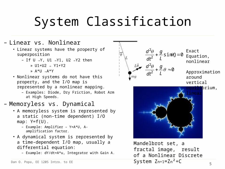
– Linear vs. Nonlinear• Linear systems have the property of
superposition– If U →Y, U1 →Y1, U2 →Y2 then
» U1+U2 → Y1+Y2» A*U →A*Y
• Nonlinear systems do not have this property, and the I/O map is represented by a nonlinear mapping.
– Examples: Diode, Dry Friction, Robot Arm at High Speeds.
– Memoryless vs. Dynamical• A memoryless system is represented by a
static (non-time dependent) I/O map: Y=f(U). – Example: Amplifier – Y=A*U, A- amplification factor.
• A dynamical system is represented by a time-dependent I/O map, usually a differential equation:
– Example: dY/dt=A*u, Integrator with Gain A.
Mandelbrot set, a fractal image, result of a Nonlinear Discrete System Zn+1=Zn²+C
0
0)sin(
2
2
2
2
L
g
dt
d
L
g
dt
d Exact Equation, nonlinear
Approximation around vertical equilibrium, linear

6Dan O. Popa, EE 1205 Intro. to EE 6
System Classification
– Time-Invariant vs. Time Varying• Time-invariant system parameters do not change over time. Example: pendulum, low
power circuit• Time-varying systems perform differently over time. Example: human body during exercise.
– Causal vs. Non-Causal• For a causal system, outputs depend on past inputs but not future inputs. Examples:
most engineered and natural systems• A non-causal system, outputs depend on future inputs. Example: computer simulation
where we know the inputs a-priori, digital filter with known images or signals.
– Stable vs. Unstable• For a stable system the output to bounded inputs is also bounded. Example:
pendulum at bottom equilibrium• For an unstable system the ouput diverges to infinity or to values causing permanent
damage. Example: short circuit on AC line.

7Dan O. Popa, EE 1205 Intro. to EE 7
System Modeling
• Building mathematical models based on observed data, or other insight for the system.– Parametric models (analytical): ODE, PDE– Non-parametric models: graphical models - plots, look-
up cause-effect tables– Mental models – Driving a car and using the cause-
effect knowledge– Simulation models – Many interconnect subroutines,
objects in video game

8Dan O. Popa, EE 1205 Intro. to EE 8
Types of Models
• White Box – derived from first principles laws: physical,
chemical, biological, economical, etc.– Examples: RLC circuits, MSD mechanical models
(electromechanical system models).• Black Box
– model is entirely derived from measured data– Example: regression (data fit)
• Gray Box – combination of the two

9Dan O. Popa, EE 1205 Intro. to EE 9
White Box Systems: Electrical
• Defined by Electro-Magnetic Laws of Physics: Ohm’s Law, Kirchoff’s Laws, Maxwell’s Equations
• Example: Resistor, Capacitor, Inductor
u
Riu
i
C
ui
L
10Dan O. Popa, EE 1205 Intro. to EE 10
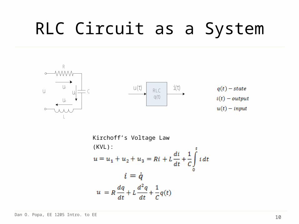
RLC Circuit as a System
Kirchoff’s Voltage Law (KVL):
u1
L
C
R
uu3
u2RLCq(t)
u(t) i(t)

11Dan O. Popa, EE 1205 Intro. to EE 11
White Box Systems: Mechanical
Newton’s Law:
M
K
BF MSD
x(t)
F(t) x(t)
Mechanical-Electrical Equivalance:
F (force) ~V (voltage)x (displacement) ~ q (charge)M (mass) ~ L (inductance)B (damping) ~ R (resistance)1/K (compliance) ~ C (capacitance)

12Dan O. Popa, EE 1205 Intro. to EE 12
White-Box vs. Black-Box Models
Newton-Euler Law:
LawnMowerx,y,θ
ω_r(t), ω_l(t) X(t), Y(t) Θ(t)

13Dan O. Popa, EE 1205 Intro. to EE 13
Grey-Box Models

14Dan O. Popa, EE 1205 Intro. to EE 14
White Box vs Black Box ModelsWhite Box Models Black-Box Models
Information Source First Principle Experimentation
Advantages Good ExtrapolationGood understandingHigh reliability, scalability
Short time to developLittle domain expertise requiredWorks for not well understood systems
Disadvantages Time consuming and detailed domain expertise required
Not scalable, data restricts accuracy, no system understanding
Application Areas Planning, Construction, Design, Analysis, Simple Systems
Complex processesExisting systems
Start to understand simple white continuous time models which are linearEventually deal with grey-box or black-box models in real-life

15Dan O. Popa, EE 1205 Intro. to EE 15
Linear vs. Nonlinear
• Why study continuous linear analysis of signals and systems when many systems are nonlinear in practice?– Linear systems have generic, predictable performance.– Nonlinear systems can be approximated and transformed
into linear systems.– Some techniques for analysis of nonlinear systems are
based on linear methods– If you don’t understand linear dynamical systems you
certainly can’t understand nonlinear systems

16Dan O. Popa, EE 1205 Intro. to EE 16
Application Areas for Systems Thinking
• Classical circuits & systems (1920s – 1960s) (transfer functions, state-space description of systems).
• First engineering applications: military - aerospace 1940’s-1960s
• Transitioned from specialized topic to ubiquitous in 1980s with EE applications to:– Electronic circuit design– Signal and image processing
• Networks (wired, wireless), imaging, radar, optics.
– Control of dynamical systems• Feedback control, prediction/estimation/identification of systems, robotics, micro
and nano systems

17Dan O. Popa, EE 1205 Intro. to EE 17
Diagram Representation of Systems
Top
Bottom 1 Bottom 2 Bottom 3
Middle
Graph Node 1
Graph Node 3
Graph Node 5
Graph Node 4
Graph Node 2
Hierarchical Diagram: Organizations
Undirected Graph: Networks Flowchart: Procedures, Software
18Dan O. Popa, EE 1205 Intro. to EE 18
System Simulation Software
• Matlab Simulink– http://www.mathworks.com/support/2010b/simu
link/7.6/demos/sl_env_intro_web.html
• National Instruments Labview– http://www.ni.com/gettingstarted/labviewbasics/
environment.htm

19Dan O. Popa, EE 1205 Intro. to EE 19
EE-Specific Diagrams
• Block Diagram Model: – Helps understand flow of information (signals) through a complex system– Helps visualize I/O dependencies– Equivalent to a set of linear algebraic equations.– Based on a set of primitives:
Transfer Function Summer/Difference Pick-off point
• Signal Flow Graph (SFG): – Directed Graph alternative
H(s)U(s) Y(s)
+
+
U2
U1 U1+U2 U U
U

20Dan O. Popa, EE 1205 Intro. to EE 20
EE-Specific Diagrams: Signal Flow Graph (SFG – Directed Graph)
2-port circuit SFG Multi-loop Control SFG

21Dan O. Popa, EE 1205 Intro. to EE 21
EE-Specific Diagrams: Block Diagram Simplification Rules

22Dan O. Popa, EE 1205 Intro. to EE 22
EE-Specific Diagrams: Block Diagram Reduction Rules

23Dan O. Popa, EE 1205 Intro. to EE 23
EE-Specific Diagrams: Block Diagram Reduction Rules

24Dan O. Popa, EE 1205 Intro. to EE 24
Robots as Complex Systems
G. Bekey definition: an entity that can sense, think and act.Extensions: communicate, imitate, collaborate Classification: manipulators, mobile robots, mobile manipulators.
Sense Think Act
Robot
25Dan O. Popa, EE 1205 Intro. to EE
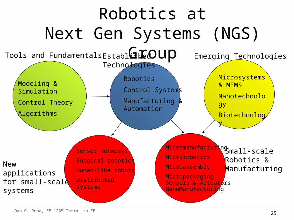
Research in Multiscale Robotics atNext Gen Systems (NGS) Group
Robotics
Control Systems
Manufacturing & Automation
Established Technologies Emerging Technologies
Micromanufacturing Microrobotics Microassembly MicropackagingSensors & ActuatorsNanoManufacturing
Microsystems & MEMS
Nanotechnology
Biotechnology
Small-scale Robotics & Manufacturing
Modeling & Simulation
Control Theory
Algorithms
Tools and Fundamentals
Sensor networks
Surgical robotics
Human-like robots
Distributed systems
New applicationsfor small-scale systems

26Dan O. Popa, EE 1205 Intro. to EE 26
NGS Research
• Micro and Nano Robotics– Manufacturable Micro and Nano Robotics
• Automated MEMS Assembly and Packaging– Mobile Microrobotics
• Sub-Millimeter size robots powered by ambient fields
• Next Generation Robotics for Healthcare– Assistive Robotics
• Treatment of cognitive and motor disabilities (Autism, CP) using Advanced Human-Robot Interaction (HRI)
– Microrobotics for healthcare application (in-vivo or in-vitro manipulation and process tools)
• Examples from recent projects – Micro Robotic Factories– UTA Microrobotics Team – Zeno and Neptune Assistive Robots

27Dan O. Popa, EE 1205 Intro. to EE 27
M³ - Multiscale (Macro-Micro) Robotic Assembly Cell
Multiscale Robotic Workcell: work volume of approximately O(1 m3), robots with dimensions of O(10-1~10-2m), handles parts of size O(10-2~10-4m), and achieves accuracies in the scale of O(10-4~10-6
m). Four precision robots sharing a common workspace, with multiple
end-effectors: microgrippers, zoom microscope, laser for solder reflow.
Control through Labview and NI motion control products
Laser solder reflow (delivery optics) – 3DOF
Zoom-camera system – 2DOF
Gripper Manipulator 4DOF
Tool tray with quickchange end-effectors
Parts trayFine manipulator3DOF
Hot plate for die attach
Packaged MOEMS device using the M³ for US Navy Schematic and Control System Diagram of M³
D.O. Popa, R. Murthy, A. N. Das, “M3- Deterministic, Multiscale, Multirobot Platform for Microsystems Packaging: Design and Quasi-Static Precision Evaluation,” in IEEE Transactions on Automation Science and Engineering (T-ASE), April 2009.
28Dan O. Popa, EE 1205 Intro. to EE 28
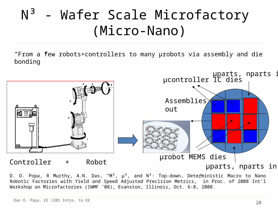
N³ - Wafer Scale Microfactory (Micro-Nano)
“From a few robots+controllers to many µrobots via assembly and die bonding”
D. O. Popa, R Murthy, A.N. Das, “M³, μ³, and N³: Top-down, Deterministic Macro to Nano Robotic Factories with Yield and Speed Adjusted Precision Metrics,” in Proc. of 2008 Int’l Workshop on Microfactories (IWMF ’08), Evanston, Illinois, Oct. 6-8, 2008.
Controller + Robot µparts, nparts in
µparts, nparts in
Assemblies out
µrobot MEMS dies
µcontroller IC dies

29Dan O. Popa, EE 1205 Intro. to EE 29
AFAM: A Millimetric Assembled 4 axis Micromanipulator for N³
Microrobot volume:2mm x 3mm x 1mm Work Volume: 50m x 50m x 75mActuation: Electrothermal Transmission: XY – direct drive
- cable drivenAll components fabricated using DRIE on 50~100 microns (device) SOI.Arm is detethered and assembled out-of-plane using passive jammer.Cable (30 m Cu wire) is cut to required length and assembled.
R. Murthy, D. O. Popa, “A Four Degree Of Freedom Microrobot with Large Work Volume”, in proc. of IEEE ICRA ‘09, Kobe, Japan, May 2009

30Dan O. Popa, EE 1205 Intro. to EE 30
ARRIpede: a Millimetric Microcrawler
System Specifications:•Volume = 1.7cm X 1.7cm X 1 cm• Weight ~ 4g (with battery)• Velocity=~2mm/s•Max Payload~9g•Resolution of 20~30nm•Repeatability better than 12 μm•Continous operation: 10 minutes at max speed, 100 minutes at .1x max speed Rakesh Murthy, A .N. Das, D. O. Popa, “Nonholonomic Control of an Assembled
Microcrawler,” in Proc. Of 9th International IFAC Symposium on Robot Control, Gifu, Japan, September 2009.

31Dan O. Popa, EE 1205 Intro. to EE 31
N³ - Wafer Scale Microfactory for Nanotechnology

32Dan O. Popa, EE 1205 Intro. to EE 32
Making the Microfactory by Automated 3D Microassembly
Control Challenges:-Larger number of robots
- Measurement uncertainty, measurement range,
- Time delays
- Fewer embedded sensors, low SNR
- Manufacturing uncertainty, inacurate robot models)
- Environmental effects (stiction, temperature)

33Dan O. Popa, EE 1205 Intro. to EE 33
NIST Microbotics Challenge 2011• Hosted at IEEE International Conference on Robotics and Automation, Shanghai, China, May 10, 2011. • 7 Qualified Teams: France (FEMTO-ST), Italy (IIT), Univ. of Waterloo (CA), 4 US Universities (Stevens,
Hawaii, Maryland, UTA• Maximum robot size: 600 microns sphere.
MobilityChallenge
MicroAssemblyEvent
Vibration and Laser Actuated
UTA Microrobots, 2011

34Dan O. Popa, EE 1205 Intro. to EE 34
UTA Vibot Control Using National Instruments PXI-8196
• Microrobot pose (x, y, θ) from NI-1742 Smart Camera• Exchange of pose data with the control interface VI via shared variables• User control of square wave output through PXI-5201 Arbitrary Waveform
Generator (AWG). Output frequency to piezoelectric actuator. PXI 7831 FPGA RIO• Data logging via control interface VI• UTA Microrobotics Team video
square waveamplitude & frequency
PXI-8196 controllerrobot posex, y, θ
PZT Actuator
arena andmicrorobot
image
user control
control interface VI

35Dan O. Popa, EE 1205 Intro. to EE 35
Advanced Human-Robot Interaction for Assistance to Children with Special Needs Interaction through advanced vision, motion control, gestures and compliant robotic skin. Interaction though Wii Remotes, Neural Brain interfaces and iPad devices. Collaboration with Heracleia Lab, UTA, Hanson Robotics Inc., UNTHSC
MicroRobotics for In-Vivo Diagnosis and Treatment Mobile microrobotics: Sub-mm size robots powered and controlled wirelessly through wireless energy fields such as EM,
vibration, or laser. Micro and Nano Assembly of Surgical Instruments for medical procedures in hard to reach places (eye, ear, brain).
Next Generation Robots for Healthcare
Interface
Wii Remote
EPOC neuroheadset
PC
VS Code
Neptune Mobile Manipulator
Encoders
Force Sensors
iPad
Camera
Recorded Results Patient
WiFi
Blue
toot
h
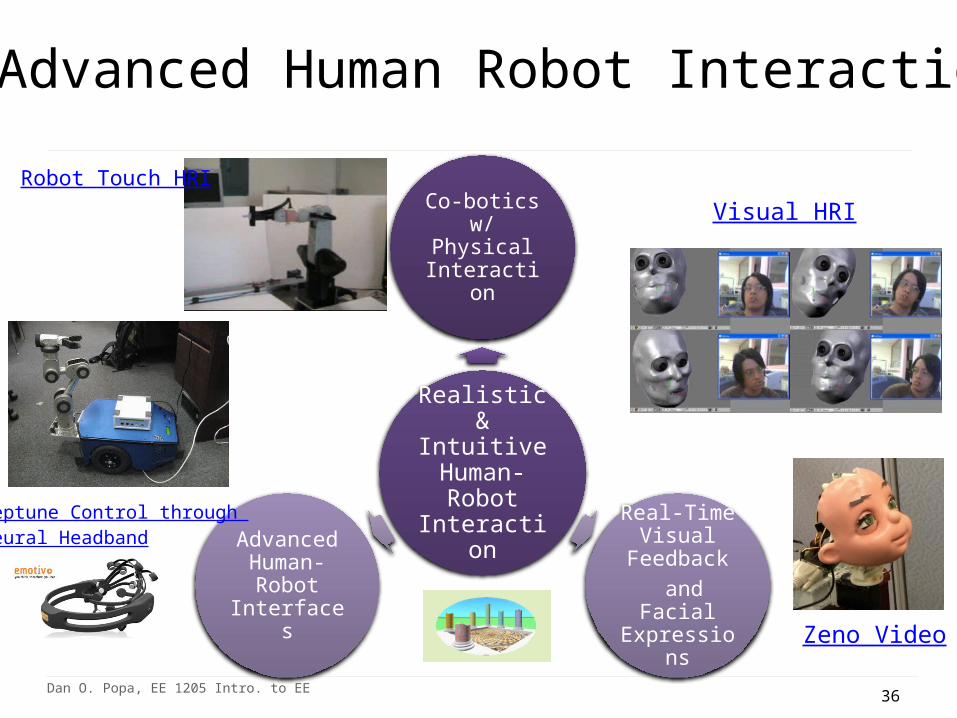
Advanced control for Zeno Robokind (by Hanson Robotics, Inc.) generating facial expressions and maintaining eye contact with NGS programmers.
Neptune Mobile Manipulator interfaced to human users through Wii Remote, Neural Headband, and Cameras, and provides assistance to users with motor impairments.
36Dan O. Popa, EE 1205 Intro. to EE
Realistic & Intuitive Human-Robot
Interaction
Co-botics w/ Physical Interaction
Real-Time Visual Feedback and Facial
Expressions
Advanced Human-Robot Interfaces
Advanced Human Robot Interaction
Zeno Video
Neptune Control through Neural Headband
Robot Touch HRI
Visual HRI
37Dan O. Popa, EE 1205 Intro. to EE
Conclusion
- Abstraction is the basis for system level thinking. Abstraction requires advanced mathematics, and it is especially required of Electrical and Computer Engineers.
- Systems are composed of building blocks used to generalize and manage complexity.
- Modeling and simulations are important building tools in systems-level approaches.
- System-level concepts are important tools in your engineering education.- System-level thinking helps manage complexity of present-day
technology, economics, society.- System-level approach originating in EE are a great advantage in
interdisciplinary projects with all your future colleagues from other departments.