1. earthwork 1.1 general 1.2 trench … · astm d 2922 & d 3017. since the composition of the...
TRANSCRIPT

BASIC SPECIFICATIONS
WATER PIPELINE CONSTRUCTION SPECIFICATIONS (In addition to Green Book Standards)
1. EARTHWORK 1.1 GENERAL (Per Green Book)
Unless otherwise approved, all pipeline trenches shall have vertical sides and shall have a minimum width equal to the outside diameter of the pipe plus 12-inches and a maximum width equal to the outside diameter of the pipe plus 16-inches.
1.2 TRENCH EXCAVATION (Per Green Book) 1.3 TRENCH AND EXCAVATION SHORING (Per Green Book) 1.4 PIPE BEDDING (Per Green Book)
Where the bottom of the trench is in rock or boulders, such material shall be removed to a minimum depth of 6 inches below the grade of the bottom of the pipe and the trench refilled to the grade of the pipe with sand or suitable selected sandy material. The material shall be properly moistened and thoroughly compacted in layers not exceeding 4 inches in thickness by means of a hand-operated, power-driven tamper.
1.5 TRENCH BACKFILL AND COMPACTION REQUIREMENTS (Per Green Book) 1.6 GEOTECHNICAL TESTING
The Developer or Contractor shall engage the services of a geotechnical engineering firm or individual licensed in the State of California to monitor soil conditions during earthwork, trenching, bedding, backfill and compaction operations. Sampling and testing procedures shall be performed in accordance with the Reference Standards and as
follows:
A. The soils technician shall be present at the site during all backfill and compaction operations. Failure to have the soils technician present will subject such operations to rejection.
B. Density and optimum moisture content of soil shall be determined by the use of the sand cone method, ASTM D 1556, or nuclear density gauge method, ASTM D 2922 & D 3017. Since the composition of the pipe and the walls of the trench have an effect on the nuclear density gauge output, a minimum of 25% of the density and optimum moisture tests shall be made using the sand cone method.
C. Determine laboratory moisture-density relations of existing soil by ASTM D
1557, Method C and/or D (formerly ASTM D 4253 and ASTM D 4254).
D. Determine the relative density of cohesionless soils by ASTM D 1557, Method C and/or D (formerly ASTM D 4253 and ASTM D 4254).
E. Sample backfill material by ASTM D 75.
F. Express "relative compaction" as a percentage of the ratio of the in-place dry
density to the laboratory maximum dry density.
A report of all soils tests performed shall be stamped and signed by the soils firm or individual and shall be submitted by the Contractor prior to the filing of the Notice of Completion or acceptance by the City. The report shall document the sampling and testing of materials, the location and results of all tests performed, and shall certify that materials and work are in compliance with this specification.
1.7 COMPACTION REQUIREMENTS (Green Book) Compaction shall be accomplished by mechanical means at the appropriate lifts for the
type of soil (1 to 2 foot maximum). Consolidation by water settling methods such as jetting or flooding is prohibited. If the backfill fails to meet the specified relative compaction requirements; the backfill shall be reworked until the requirements are met. All necessary excavations for density tests shall be made as directed by the Soils Technician, and as acceptable to the City. All excavations are subject to compaction tests.
Compaction tests shall be performed at random depths, and at random intervals not to exceed 300-feet, and in addition at least 20% of all service laterals shall be tested as directed by the Soils Technician or City.
1.8 CONTROL OF WATER
The Contractor shall provide and maintain at all times during construction, ample means and devices with which to promptly remove and dispose of all water entering the excavations or other parts of the work. Ground water shall not be allowed to rise around pipe installations until jointing compound in the joints has set. The Contractor shall dispose of the water from the work in a suitable manner without damage to adjacent property. No water shall be drained into work built or under construction. Water shall be disposed of in such a manner as not to be a menace to the public health.
Dewatering for structures and pipe lines shall commence when ground water is first encountered, and shall be continuous until such times as water may be allowed to rise in accordance with the provisions of this Section.
2. WATER PIPE INSTALLATION 2.1 GENERAL
The Contractor shall furnish and install all water pipeline material required for the construction of the water pipeline and appurtenances as herein specified and shown on the Drawings. All pipeline material shall be installed per manufacturer's published recommendations and per the applicable published standards for the particular material being installed unless otherwise modified herein. In case of any conflict, the most stringent and highest requirement shall govern, and the Contractor shall adhere to said requirement.
2.2 INSTALLATION
Pipe shall be accurately laid to alignment and grade shown on Drawings or established by City. Each section of pipe shall be lowered into trench in a manner that will prevent injury to pipe, coating, or joints and shall be carefully bedded to provide continuous bearing and prevent uneven settlement. Inside of pipe shall be clean and free from foreign material of any kind before being installed. Contractor will lay pipe units with bell ends in direction of laying, unless otherwise ordered by City or set forth in these Specifications and Drawings.
2.3 HANDLING
Contractor may find it necessary to move or haul pipe during progress of the work. Dropping or bumping of pipe will not be permitted, and all damaged pipe will be rejected. Rejected pipe may be repaired if permitted by City, and such repairs shall be subject to approval of City.
Contractor shall take all necessary precautions to prevent pipe from floating due to water entering trench from any source, shall assume full responsibility for any damage due to this cause, and shall restore and replace pipe to its specified condition and grade if it is displaced due to floating. Contractor shall maintain inside of pipe free from foreign materials and in a clean, sanitary condition until its acceptance by City.
At all times when work of installing pipe is not in progress, all openings into pipe and ends of pipe in trench shall be tightly closed to prevent entrance of animals and foreign materials.
2.4 JOINTS (CML/CMC PIPELINES)
Water pipeline joints shall be constructed in accordance with City Standards. All rubber gasket joints shall be bonded (in the field) per City Standard. Where indicated on the Drawing, Contractor shall install insulation flange kits in accordance with City requirements.
2.5 FIELD JOINTS - CEMENT MORTAR LINING
Mortar shall be Hubs all patch quickset non shrink commercial grout or a City approved equal packaged dry mortar mix consisting of one part cement and three parts sand. Quantity of water shall be sufficient so that when mortar is firmly compressed into a ball shape, it will hold its shape without slump. Mortar shall be mixed separately for each joint to be patched.
Special care should be taken to avoid damage to lining or coating during lowering pipe into trench.
2.6 FIELD JOINTS - CEMENT MORTAR COATING
Outside field joints are required to be coated with cement-mortar. This shall be accomplished by wrapping a canvas or paper diaper around the joint. The diaper is held on each side by steel strapping. Cement mortar shall be composed of 1 part cement and not more than 3 parts sand and mixed to a consistency of thick cream. The top of the pour must be covered with a protective material, such as cloth or paper.
2.7 CURVED ALIGNMENT
Laying pipe on curved alignment with unsymmetrical closure of spigot into bell rings shall be permitted as recommended by pipe manufacturer. For the purpose of reducing angular deflection at pipe joints and for closure sections, Contractor shall be permitted to install pipe sections of less than standard length. Closing courses and short sections of pipe shall be fabricated and installed by Contractor as found necessary in the field. Where closing pieces are required, Contractor shall make the necessary measurements and shall be responsible for their correctness.
2.8 MANUFACTURER ACCESS
Pipe manufacturer shall have free access to the work during laying operations and testing. Any improper act on the part of Contractor which pipe manufacturer may observe shall be reported to City.
2.9 ALLOWABLE VARIATIONS IN PIPELINE ALIGNMENT
Pipeline cover as shown on the attached Standard Drawings and/or the Design Drawings, is hereby defined to be Design Cover over pipeline. Therefore, should field conditions determined at time of construction show that any pipe grade changes are required, City reserves the right to authorize said changes in pipeline grades, and Contractor shall trench and lay pipeline accordingly.
All pipelines within public roadways shall be installed with no less than 42-inches of cover below road grade (or projected existing road grade, in case of embankments) unless otherwise shown on the Drawings or approved by the City.
2.10 PVC WATERLINES
Each section of pipe shall be lowered into the trench in a manner that will prevent injury to the pipe, or joints and shall be carefully bedded to provide continuous bearing and prevent uneven settlement. The inside of the pipe shall be clean and free from foreign material of any kind before being installed.
For PVC pipe and ductile iron pipe with mechanical joints, the gasket shall be placed in the groove of the bell. Lubricate the spigot end into the bell and force into position per manufacturer's recommendation. See attached Pipeline Manual page 11 Trenches shall be in a reasonably dry condition when the pipe is laid. Necessary facilities shall be provided for lowering and properly placing the pipe sections in the trench without damage. The pipe shall be laid carefully to the lines and grades given and the sections shall be closely jointed to form a smooth flow line. Where no grades are given, pipe shall be laid in a smooth continuous grade between connections to other mains, blow-offs and/or air release valves. Immediately before placing each section of pipe in final position for jointing, the bedding for the pipe shall be checked for firmness and uniformity of surface. For convenience of testing, the pipeline may be divided into sections and each section tested separately. All pipes shall be tested under a pressure 1-1/2 times the pressure rating of the pipe, but not less than 150 psi. Maximum test pressure shall not exceed that determined by the City. If any leakage is evidenced in the testing of the pipeline, the various sections of the pipeline shall be isolated for testing between available valves, or between bumpheads located as approved by the City. The maximum allowable leakage for PVC pipe shall be six (6) gallons per day per mile of pipe per inch of pipe inside diameter. If the leakage exceeds this amount, the section being tested will be considered defective. The Contractor shall determine the points of leakage, make the necessary repairs and perform another test. This procedure shall be continued until the leakage in each section falls below the allowable maximum for that section of pipeline. The Contractor shall provide all calibrated meters for measurement of leakage, all bumpheads or skillets, piping, calibrated gages, pumps and other equipment, all water not furnished by City, and all power and labor necessary for the performance of pressure tests satisfactory to the City. The Contractor shall furnish all necessary equipment and labor to fill each section of pipeline tested and for pumping the water from one test section to another as may be necessary for obtaining and maintaining the required water pressure and for filling the entire pipeline with water after the conclusion of the testing, as hereinafter provided. The Contractor, at his own expense, shall do any excavation necessary to locate and repair leaks or other defects which may develop under test, including removal of backfill already placed, shall replace such excavated material, and shall make all repairs necessary to meet the required water tightness after which the test shall be repeated until the pipe meets the test requirements. All tests shall be made in the presence of the City. After the pipe has successfully met all test requirements specified herein, the entire pipeline shall be filled with water and so maintained until the completion of the contract unless otherwise ordered by the City.
Thrust restraint shall be accomplished by the use of restrained joints as specified herein. Thrust blocks will not be allowed for PVC pipelines unless otherwise ordered by the City.
2.11 Locator Wire
Locator wire shall be installed over all PVC waterlines, non-ferrous services and pipelines. Locator wire shall be 14-1 solid insulated copper wire (UF), in a continuous strand, placed on top of pipe and secured with tape. Locator wire shall be brought to the surface at all appurtenances (i.e. fire hydrants, water services, air valves, blowoffs, etc.), thus providing continuous "looping" between the appurtenances and the water main.
After all trench backfill operations are complete, the Contractor shall conduct the conductivity test to confirm that the wire is continuous. The Contractor shall be responsible for all costs to confirm, locate, and repair any breaks in the locator wire identified in the conductivity test. The Contractor is advised to use care in the installation and backfilling operations to prevent damage to the wire. Splices shall be made at locations approved by the City. The wire connecting device shall be an underground electrical wire connector to splice and effectively moisture-seal the conductors. Wire connectors shall be approved by the City and shall be UL listed and CSA certified for direct burial splices.
3. WELDING SPECIFICATIONS 3.1 GENERAL
All welding operators shall be qualified under the Standard Qualification Procedure of the American Welding Society and all applicable provisions of the latest edition of "Structural Welding Code" (ANSI/AWS D1.1) published by the American Welding Society are incorporated into this Specification. Contractor shall adhere to all Cal-OSHA, American Welding Society, American National Standards Institute and local agency safety regulations (including fire) regarding all welding operations. The City shall have the right at any time to call for and witness making of test specimens by any welder in accordance with these Specifications, and the expense of such tests shall be borne by Contractor. The provisions of these sections do not apply to the fabrication of pipe or special fittings in conflict with AWWA Standard Specifications for pipe. All hand welding in both shop or field shall be done by welders certified in accordance with ASA B31.1 latest (AWWA C-206-latest). All welds shall be made by an electric shielded arc method of welding. Plates shall be held in correct position. Abutting edges shall be properly prepared. Each deposited layer of welded metal shall be thoroughly cleaned before additional metal is applied to its surface. Finished weld bead shall be central to the seam, and the finished joint shall be free from depressions, undercut edges, burrs, irregularities resulting from welding, other than normal bead necessary. All welds shall be a type that will produce complete fusion with base metal and shall be free from cracks, oxides, and gas pockets within the limits set forth under these Specifications. If the automatic welding machine does not obtain a fusion weld that will
penetrate through to the inside of the pipe and protrude beyond the contour of the plate surface, an inside pass shall be made in the root of the groove on the inside of the pipe. Chipping out of the weld in the root of the groove will be required when deemed necessary by the City. If welding is stopped for any reason, special care shall be taken when welding is resumed to obtain complete penetration between welded metal, plate, and welded metal previously deposited, and if flux is used, it must be redistributed before work is resumed. The height of the outside weld bead above the contour of the plate surface shall be measured and shall be not less than 1/16-inch. Heights of the outside weld bead above the contour of the plate surface exceeding l/8-inch shall be removed by grinding or chipping. Welds found deficient in dimensions but not in quality shall be enlarged by additional welding after thorough cleaning of the surface of previously deposited metal and adjoining plate. However, if work performed since making a deficient weld has rendered the weld inaccessible or has caused new conditions which would make such reinforcement dangerous or ineffective, the original conditions shall be restored by removal of welds, members, or both, before enlarging the deficient weld or the deficiency shall be compensated by additional work as prescribed by the City. Welds considered by the City to be deficient in quality or made contrary to any mandatory provision of these Specifications shall be removed by chipping or melting and shall be remade. The weld metal shall be removed throughout its depth to expose clean base metal, but if a strictly local deficiency, the weld need not be removed throughout its entire length, provided that sufficient amount shall be removed to insure that sound weld metal only remains. A cracked weld shall be removed throughout its length. When removing part or all of a weld by cutting or chipping, such cutting or chipping shall not extend into the base metal beyond the depth of weld penetration. When removing part or all of a weld by melting, care shall be taken not to burn or otherwise injure the base metal. After the melting operation, burned metal shall be removed to clean, sound metal. Overheated weld metal and any overheated base metal adjoining same shall be removed and replaced by new weld metal properly applied. However, if the plate is so badly or extensively injured by overheating that it cannot satisfactorily be replaced by weld metal, such additional work as prescribed by the City shall be performed. All longitudinal, spiral, and girth seams of straight pipe sections, and special sections when practicable, shall be welded with an automatic welding machine. If requested, sample welds shall be submitted to the City for testing in accordance with these Specifications. Approval of such tests shall be required prior to welding of pipe. Fillet welds shall have full penetration into the corner. Excessive cutting back of the edges of fillet welds is a defect and shall be repaired. Butt welds shall be made by adding weld metal to both sides of the joint, and the underside of the weld in groove shall be chipped out, removing all slag and unsound metal, containing a clean surface for the application of weld metal; in making butt and fillet welds, weld metal shall be
deposited in successive layers, so there will be as many passes as there are complete multiples of 1/8-inch in the plate thickness, provided there shall be a minimum of two passes.
3.2 FIELD WELDED PIPE JOINTS
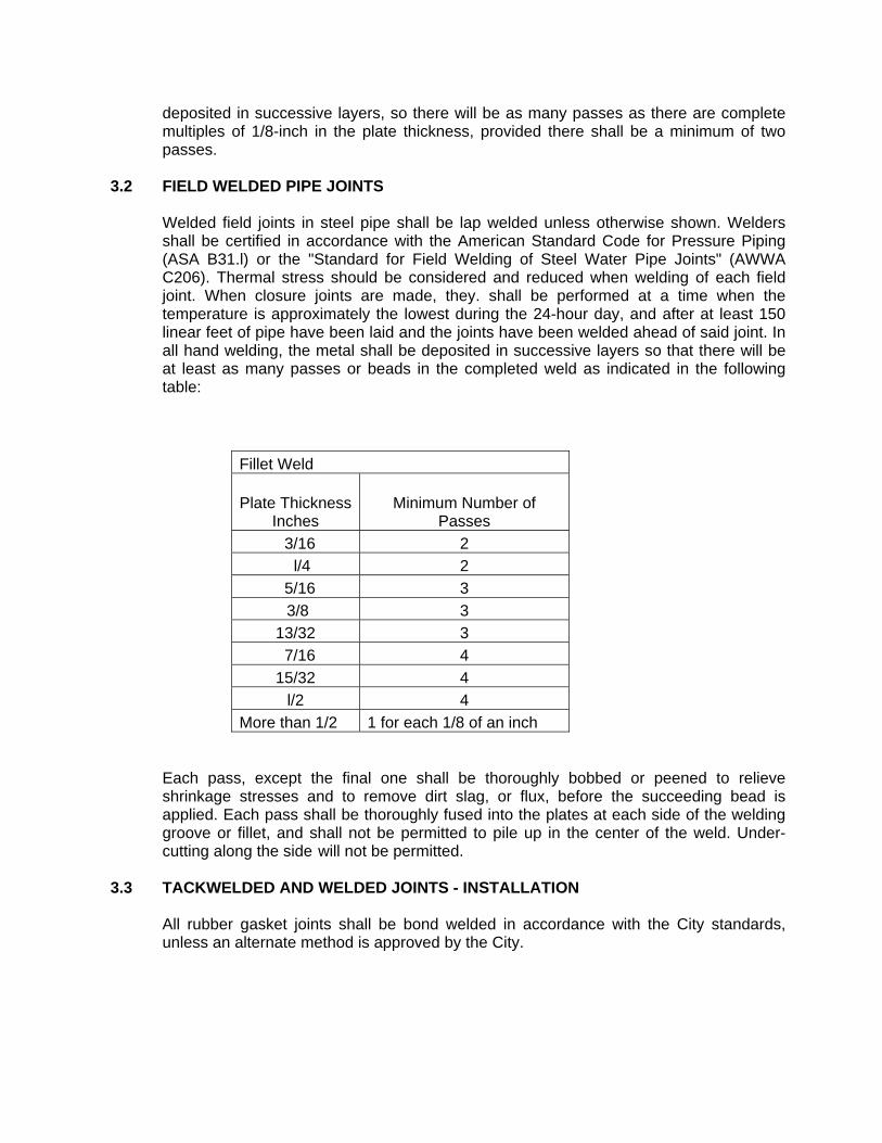
Welded field joints in steel pipe shall be lap welded unless otherwise shown. Welders shall be certified in accordance with the American Standard Code for Pressure Piping (ASA B31.l) or the "Standard for Field Welding of Steel Water Pipe Joints" (AWWA C206). Thermal stress should be considered and reduced when welding of each field joint. When closure joints are made, they. shall be performed at a time when the temperature is approximately the lowest during the 24-hour day, and after at least 150 linear feet of pipe have been laid and the joints have been welded ahead of said joint. In all hand welding, the metal shall be deposited in successive layers so that there will be at least as many passes or beads in the completed weld as indicated in the following table:
Fillet Weld
Plate Thickness Inches
Minimum Number of Passes
3/16 2
l/4 2
5/16 3
3/8 3
13/32 3
7/16 4
15/32 4
l/2 4
More than 1/2 1 for each 1/8 of an inch
Each pass, except the final one shall be thoroughly bobbed or peened to relieve shrinkage stresses and to remove dirt slag, or flux, before the succeeding bead is applied. Each pass shall be thoroughly fused into the plates at each side of the welding groove or fillet, and shall not be permitted to pile up in the center of the weld. Under-cutting along the side will not be permitted.
3.3 TACKWELDED AND WELDED JOINTS - INSTALLATION
All rubber gasket joints shall be bond welded in accordance with the City standards, unless an alternate method is approved by the City.
The pipe manufacturer shall direct the Contractor on the method of welding the fully welded joints, or the cut-to-fit joints, in order that the joints shall not pull apart or leak when subjected to design pressures stated herein.
4. ELBOWS, SIDE OUTLETS, TEES, BUTTSTRAPS, CROSSES
For steel pipe, all elbows, side outlets, top outlets, tees, crosses, etc., shall be furnished by the Contractor and shall be shop fabricated in accordance with A.W.W.A. C-208 (latest); except the minimum radius for all bends shall not be less than 2.5 times the nominal diameter of the pipelines. Whenever the Contractor must perform minor amounts of field fabrication, he will be required to do all fabrication in a manner such that the lining and wrapping/coating may be repaired by hand to a quality equal to the shop applied lining and wrapping/coating. Buttstraps, shear rings, etc. shall be per the applicable A.W.W.A. Standards or Manuals.
Service outlets shall be constructed in accordance with the Standard Drawing.
Wherever collar reinforcement is required, both the collar and the plain-end of the flanged x p.e. (plain-end) outlet shall be pre-shaped to mate with curvature of the main line pipeline, and both the collar and the flanged x p.e. (plain-end) outlet shall be welded into place. All collar and wrapper reinforcing shall be in accordance with the following reinforcement guides:
A. Steel Pipe, Design and Installation, A.W.W.A. Manual M-ll, latest. B. An equal pipeline manufacturer's reinforcing guide, as approved by City.
C. API-ASME Code for Unfired Pressure Vessels for Petroleum liquids and gases.
If case of conflict, the highest and most stringent standard shall govern.
5. DUCTILE-IRON PIPE
Ductile-iron pipe and ductile iron fittings shall be installed in accordance with the applicable sections of AWWA C600. The Contractor shall furnish and install all pipe, specials, fittings, closure pieces, valves, supports, bolts, nuts, gaskets, jointing materials, and all other appurtenances as shown on the Approved Plans and as required to provide a complete and workable installation. At all times when the work of installing pipe is not in progress, including worker break times, ends of the pipe shall be closed with vermin-proof and child-proof caps or plugs. Do not permit trench water to enter the pipe. Do not place tools, clothing, or other materials in the pipe. The Contractor shall maintain the interior of the pipe in a sanitary condition free from foreign materials. Install pipe according to the manufacturer's approved order of installation. Install pipes uphill if the grade exceeds 10%. Lower the pipe onto the bedding at the proper lines and grades.
The manufacturer's printed installation guide outlining the radius of curvature that can be negotiated with pipe sections of various lengths shall be followed, except they shall not exceed the deflections allowed in AWWA C600 according to joint type. Combined deflections at rubber gasket or flexible coupling joints shall not exceed that recommended by the manufacturer. The pipe shall have firm bearing along its full length, and bell holes shall be provided at each joint to permit visual inspection of the joint and prevent the pipe from being supported by the bell end or coupling. Pipe Assembly: 1. Push-On Type: Assemble the pipe joint using a lubricant recommended by the manufacturer. Insert the spigot end into the bell or coupling to the proper insertion mark. Check that the elastomeric ring has not left the groove during assembly by passing a feeler gauge around the completed joint. Drive spigot ends of the pipe into bell ends in accordance with the manufacturer’s recommendations. Stabbing shall not be permitted. 2. Mechanical Joint Type: Assembly of mechanical joint fittings shall be in accordance with the manufacturer's recommendations regarding installation. Bonding of joints to provide continuity, flange insulation kits, internal epoxy linings, and other cathodic protection items and materials shall be installed where shown on the Approved Plans in accordance with the City Standards. All ductile-iron pipe and fittings buried underground shall be protected with a polyethylene encasement wrap in accordance with AWWA C105. Wrap shall be a loose 8-mil thick LLD polyethylene tube or a 4-mil thick HDCL polyethylene tube. All joints between plastic tubes shall be wrapped with 2-inch wide, 10-mil thick, polyethylene adhesive tape.
6. FILLING, TESTING, AND CHLORINATION
Upon completion of laying, joining, and backfilling, and after pipe lengths comprising the line are not less than 7 days old, and prior to resurfacing, pipeline shall be hydrostatically tested. Prior to performing the test, the section of pipeline to be tested shall be filled with water and placed under a slight pressure for at least 48 hours. Required test pressure shall then be applied and maintained for a 4-hour period. Water required to maintain test pressure shall be measured by meter or other means acceptable to City. Contractor shall provide all necessary thrust restraint required for the hydrostatic testing. Contractor shall either install the proposed pipelines about 3-feet to 4-feet short of the connection points to the existing pipelines or install to valve using an approved test plate. Hydro-static/leakage tests SHALL NOT be performed against closed valves that separate the proposed system from the existing system. The Contractor shall fill all new pipelines (through an approved backflow device) with construction water and may obtain said construction water through hydrants, blow-offs, etc.
Care shall be taken to see that all air vents are open during filling. After section has been completely filled, it shall be allowed to stand under slight pressure for a sufficient length of time to allow escape of air from any air pockets. During this period all fittings, and connections shall be examined for leaks. If any are found, they shall be stopped, using a method approved by City. The required test pressure shall then be applied and maintained for the 4-hour period. All tests shall be made in the presence of the City Inspector. The measured leakage shall not exceed 6 gallons per diameter per mile per 24-hours. Should leakage exceed this amount, the section being tested will be considered defective and Contractor shall determine points of leakage, make necessary repairs, and conduct a second test. This procedure shall be continued until leakage equals or is less than the allowable mini-mum. Note:-No leakage is allowed for welded steel pipe with fully welded joints. Contractor shall provide calibrated meters for measurement of leakage, necessary bulkheads, piping, gauges, pumps, power, and labor, and furnish everything necessary for making all tests required, at his own expense, and shall furnish to City copies of all tests performed. The City will provide the pressure gauge to be utilized for pressure testing purposes. All pipes shall be pressure tested to at least 150% of the pipe class rating; i.e. Class 150 = 225 psi test pressure, as measured near the low point of the section of pipe being tested.
7. DISINFECTING PIPELINES
Contractor shall furnish all equipment, labor, material, and water for proper disinfection of pipelines. Disinfection shall be accomplished by chlorination after lines have been tested for leakage but before they have been connected to existing system. The new mains shall be cleaned and flushed prior to disinfection. The flushing velocity to be obtained for pipes 12-inches and smaller in diameter shall not be less than 2.5 feet per second. The Contractor shall make the necessary arrangements to attain the minimum velocity. The Contractor shall take due precaution in providing for adequate drainage from the site. The entire pipeline, including all valves, fittings, hydrants, service laterals, and other accessories, shall be disinfected in accordance with the specifications provided herein. A chlorine gas-water mixture shall be applied with a solution-feed chlorinating device. DOSAGE APPLIED TO WATER WITHIN PIPELINE SHALL BE AT LEAST 50 PPM. Chlorinated water shall be retained in pipeline long enough to destroy all non-sporeforming bacteria. This period shall be at least 24 hours. After chlorine-treated water hasbeen retained for required time, CHLORINE RESIDUAL AT PIPE EXTREMITIES AND AT OTHER REPRESENTATIVE POINTS SHALL BE AT LEAST 25 PPM. Following chlorination, all disinfection water shall be thoroughly flushed from the pipeline.
The flushed water shall have a residual chlorine content not to exceed 0.10 mg/l prior to discharging into the storm drain system. The flushing operation shall be in accordance with the California Regional Water Quality Control Board requirements. Dechlorination prior to or during flushing may be required. The Contractor shall provide adequate drainage from the site. Should initial treatment fail to produce satisfactory disinfection of the pipeline as evidenced by the chlorine residual and/or the bacteriological test results, the chlorination procedure shall be repeated until acceptable results are obtained. Contractor shall use caution in discharging any highly chlorinated water, and shall be responsible for obtaining any necessary permission and permits from regulatory agencies. If required, the Contractor shall apply a reducing agent to the solution to neutralize residual chlorine or chloramines remaining in the water at his expense. Bacteriological tests required by the Health Department shall be taken and conducted by a laboratory selected by the City. The bacteriological sampling shall be as follows:
1. Pipeline disinfected and flushed until the chlorine residual matches that of the source water.
2. Bacteriological samples shall be collected 24 hours after the completion of flushing.
3. A second set of bacteriological samples shall be collected 24 hours after taking the first set of samples.
4. The bacteriological sample analysis shall be provided to the City for review. All samples must be negative for bacteria with a HPC of less than 500
5. The City will approve the activation of the pipeline after two consecutive bacteriological samples have met the criteria noted above.
All costs for testing shall be paid by the Contractor. All retesting shall conform to City requirements. Unless otherwise specified herein, minimum requirements for disinfection and bacteriological testing of new pipelines shall be in accordance with ANSI/AWWA C651 except as modified herein; and the location and number of all tests shall be determined by the City, with approval by the State Health Department.
8. CONNECTIONS TO EXISTING WATER SYSTEM
Contractor shall furnish and install connections to the existing water systems at locations shown on Drawings. Prior to connecting to the existing water system, the Contractor shall "pothole" the connection location(s) and provide this information to the City for approval prior to making the connection. The contractor shall perform all work required including any necessary field measurements, cuts-to-fit, temporary connections, and field fabrications to meet existing conditions. Connections SHALL NOT be made between existing City pipelines and proposed pipelines until successful hydrostatic/leakage and disinfection testing of the proposed pipelines has been completed. Upon successful completion of the hydrostatic/leakage and disinfection testing and only upon approval by the City, final connections can be
made to the existing pipelines. The pipeline material and appurtenances utilized to make the final connections shall be "swabbed" with a high strength chlorine solution. Contractor shall construct all said connections so that any downtime of existing water systems, due to connection work, shall occur during normal working hours as directed by City. Contractor shall cooperate with City in scheduling said connections. City will operate all existing valves necessary for Contractor to accomplish said connection work.
9. TAPPING
Connections to existing pipelines shall be made with the installation of tees or wrappers as designated on the plans. The connection sequence shall be as follows: The existing pipeline shall be drained; the tee or wrapper with valving shall be installed; and City approval of the connection shall occur prior to the re-filling of the existing pipeline. In certain instances, and only where approved in writing by the City, wet tapping will be allowed as follows:
WATER MAINS
Where connections to existing water mains are made by wet tapping, the Contractor shall perform all required excavation and shall furnish the tapping saddle and gate valve. The authorized contractor will install the tapping saddle and gate or plug valve and make the wet tap. The Contractor shall pour the thrust block, backfill, complete all compaction of backfill, make closure, set the gate "can" and cover, make all necessary pavement repairs and complete the installation in accordance with the Plans and these Standards.
WATER SERVICE
Where connections to existing water mains are made by wet tapping, the Contractor shall furnish and install all necessary material and perform all required hand and machine excavation, backfill and pavement repair. The Contractor will perform the actual wet tapping.
10. PROTECTION OF DOMESTIC WATER MAINS FROM CONTAMINATION
The Contractor shall protect all domestic water mains from contamination by any existing septic tank and/or leach line facilities, etc., which may be adjacent to the jobsite.
11. CALIFORNIA REGIONAL WATER QUALITY CONTROL BOARD, SANTA ANA
REGION PERMIT
Contractor shall channel (using sandbags or other means) flushing flow. Contractor shall protect all property from flooding and other damage during flushing operations. Contractor shall post "flooding ahead" signs in streets as required and as directed by the City. Because of demand on existing water system, the City may require Contractor to flush the pipeline over several days, in the evenings, weekends, or holidays. Contractor shall not allow any discharges from the construction site which may have an adverse effect on receiving waters of the United States. Discharged water shall meet chlorine residual levels established by the appropriate State Water Quality Control Board. Dechlorination prior to or during flushing may be required.
12. STEEL CASING (Per Green Book) 13. JACKED STEEL CASING (Per Green Book) 14. CORROSION PROTECTION
Where indicated on the Drawings, cathodic protection test stations and/or flange insulation kits with test stations shall be constructed in accordance with the applicable City Standards. All materials furnished under this specification shall be standard products from manufacturers regularly engaged in the manufacture of such products and shall be the manufacturer’s latest design that complies with the specification requirements. Electrical continuity bonding cables shall be installed across all buried or submerged metallic inline valves, flexible couplings, grooved couplings, pipe joints that are not circumferentially welded, and all other pipe joints except flange joints equipped with insulation gaskets. Where shown on the drawings, bonding cables shall be installed in vaults. All test cable and bonding cable shall be stranded copper wire with insulation rated at 600 volts. Cable with cut or damaged insulation is not acceptable. All cable shall be of sufficient length to extend from the point of connection to the appropriate corrosion monitoring test box without splices. The cable shall have a 7/64-inch thick, high molecular weight polyethylene (HMW/PE) insulation specifically designed for cathodic protection service and suitable for direct burial in corrosive soil or water, conforming to ASTM D 1248, Type I, Class C, Category 5 (HMW/PE Type CP) Grade E-5 or J-1. Test cable shall have at least 18-inches of slack in the test box. Cable size shall be in accordance with the Standard Drawings. All wires terminating in CP Test Boxes shall be identified with brass tags securely attached to the wires with nylon fasteners. The tags shall be 1½-inches in diameter, 1/16-inch thick, and shall be die-stamped with identifying letters and numbers ¼-inch high. All test stations shall be installed behind existing or proposed curbs or otherwise and out of traffic lanes to allow safe access for personnel during testing. A utility marker post shall be installed, in accordance with the Standard Drawings, when indicated on the Approved Plans. Copper sulfate reference electrodes shall be placed 12-inches away from the pipe at spring line. Electrodes shall be placed at the opposite side of the pipe from anodes. Saturate packaged electrode in 5-gallons of water prior to installation. Backfill material around the electrode shall be as specified for the pipeline trench. Installation shall be in accordance with the Standard Drawings.
All buried test cable requiring trenching to the test station box location shall be installed, without splices, in a conduit in the trench at a minimum depth of 36-inches. Care shall be taken when installing wire and backfilling trench to prevent damage to the installation. Damaged wire shall be replaced in entirety. Brass identification tags shall be used to identify all cables in all test boxes. Care shall be taken to accurately maintain the wire identities. The tags for all test cables shall be stamped with the City’s name, the pipeline size, the contents of the pipeline, and the direction of the connection point along the pipe, in accordance with the Standard Drawings. Copper sulfate reference electrode tags at cathodic test boxes shall be stamped “CuSO4". The tags shall be securely attached to each wire with nylon fasteners prior to pipe backfilling operations. The Contractor shall test the cathodic protection installations in the presence of the City. Contractor shall notify City of proposed test dates and times a minimum of 48 hours in advance. As a practical approach, the Contractor may choose to verify pipe continuity and flange isolation (described in Items A and B below) prior to backfilling as an unofficial test. Official testing shall occur after the backfilling and installation of the test boxes.
A. Pipeline Electrical Continuity Testing: Test the electrical continuity of all sections of pipe to be monitored between each pair of adjacent corrosion monitoring test stations or between the ends of pipe sections. Each pipe section shall be considered electrically continuous when the measured longitudinal resistance of each pipe section is no greater than 20% higher than the theoretical resistance of that section of pipe. If testing indicates inadequate electrical continuity, the Contractor shall excavate to investigate and locate improperly bonded pipe joints and make repairs until electrical continuity is accomplished to the satisfaction of the City.
B. Insulated Pipe Flange Testing: Each insulated pipe flange will be tested for
effective electrical isolation of the two mating pipe flanges. The insulated pipe flange shall be judged for effectiveness in accordance with NACE RP0286, Section 7, Field Testing and Maintenance." The Contractor shall replace or repair any insulated pipe flange assembly until electrical discontinuity is accomplished.
At the completion of the testing, a report of the results will be prepared and presented to the City. The report shall be typed and shall include, at a minimum, test locations, date of tests, name of technician, testing methods, voltage measurements, and theoretical and calculated resistance.
15. VIDEO INSPECTION (CML/CML WATERLINES)
Upon completion of the installation and backfill of the water pipeline, appurtenances, services, etc. and prior to filling the pipeline with water for the pressure test, the Contractor shall notify the City that the pipeline system is ready for video inspection. Said notification shall be made at least three working days in advance of the actual video inspection date. The video inspection will be made by a video inspection company
approved by the City and shall be made in the presence of the City Inspector. Prior to the video inspection, the contractor shall be responsible to provide the following items: A. Clean water pipelines free of all dirt, rock, debris, etc. B. Labor and equipment necessary to excavate the pipeline and provide camera access
ports. Access ports shall not exceed 1000 feet in spacing shall be located at all bends in excess of 22°. Also, labor and equipment necessary to repair the access ports to the satisfaction of the City.
C. Drivable truck access to each access port within the system to be videoed. D. Provide all traffic control methods required. Should any of the aforementioned items not be in compliance by the time the video inspection is to occur, the Contractor shall be subject to compensating the City for all costs incurred. Upon completion of the video taping of the subject waterlines, the Contractor shall reconnect the piping and backfill all access ports. The video inspection company will provide the City with the color DVD and a written report detailing the condition of the interior of the mainline and joints. Subsequent to review of the DVD and report by the City, the City will notify the Contractor within three business days that he may then proceed with the filling, testing, and disinfection of the pipeline; or the City will provide a list of corrective measures that must occur prior to acceptance. Should remedial activities be necessary, the reconstruction methodology shall be approved by the City prior to commencement of the work. Upon completion of the remedial construction, the Contractor shall once again notify the City that the waterlines are ready for a video inspection. The City reserves the right to re-video any portions of the water system they determine may have been affected by the reconstruction work activities.
VIDEO INSPECTION COMPANY REQUIREMENTS
(Closed Circuit Television Inspection - CCTV)
1. Rotating lens camera with articulating head. 2. Scanning capabilities of 360°. 3. Operative in 100% humidity conditions. 4. Lighting for the camera shall minimize reflective glare. 5. Lighting and camera quality shall be suitable to provide clear, in focus picture
of the entire periphery of the pipe for all conditions.
6. Camera focal distance shall be adjustable through a range from 6" to infinity. 7. Remote reading distance (footage) counter shall be accurate to one percent
(1%) over the length of the particular section being inspected. 8. The camera, television monitor, and other components of the color video
system shall be capable of producing a minimum of 350 line resolution. 9. Documentation consisting of a DVD data disk and a written report detailing
the condition of the mainline and joints shall be submitted to the City inspector immediately following the video inspection.
10. All video equipment used for domestic water systems shall Be certified for
domestic waterline inspection only and shall never have been utilized in a non-potable system.
16. PAINTING SPECIFICATIONS (Per Green Book) 17. CONCRETE WORK (Per Green Book)
BASIC SPECIFICATIONS
SEWER PIPELINE CONSTRUCTION SPECIFICATIONS (In addition to Green Book Standards)
1.1 Earthwork 1.1.1 General (Green Book) 1.1.2 Clearing and Grubbing (Green Book) 1.1.3 Grading Along Pipeline (Green Book) 1.1.4 Trench Excavation General (Green Book) Limit of Excavation (Green Book). Tunneling
Tunneling will be permitted only where native earth is of such firmness that it will remain in its original position, without sloughing off, throughout the work of excavation and backfilling; if sloughing occurs, the roof of the tunnel shall be broken down and the trench excavated as an open trench as herein specified.
Trench Width
The maximum allowable trench width, at the top of the pipe, is the outside diameter of the barrel plus ten (10) inches on either side of the exterior of the pipe barrel. Where the trench width at the top of the pipe is wider than ten (10) inches on either side of the exterior of the pipe barrel, the pipe shall be backfilled from the bottom of the trench to a level one-fourth (1/4) of the diameter above the center of the pipe with Class "B" concrete to form a cradle for the pipe, or with -crushed rock as directed by the City.
1.1.5 Trench and Excavation Shoring (Green Book) 1.1.6 Pipe Bedding General
All pipe bedding shall be of the type indicated on the plans and shall be in accordance with the pipe bedding Standard Drawings.
Unstable Material (Green Book)

Rock
Where rock is encountered, it shall be removed below grade, and the trench backfilled with suitable material to provide a compacted earth cushion with a thickness under the pipe of not less than 1/2 inch per inch of nominal diameter of the pipe to be installed, with a minimum allowable thickness of 6 inches.
1.1.7 Special Crushed Rock Bedding
When groundwater is encountered in the excavation, or when soft, spongy and unstable material is encountered in the bottom of the trench, and when approved by the City, the material in the bottom of the trench shall be removed to a depth directed by the City and replaced with 3/4 inch maximum crushed rock bedding. The crushed rock bedding shall be installed and compacted as shown on the Standard Drawing within these Specifications. The 3/4 inch maximum crushed rock material shall be approved by the City before use. In addition, two (2) slurry cofferdams shall be placed between each manhole as approved by the City.
Crushed rock shall be the product of crushing rock or gravel. Fifty percent of the particles by weight retained on a 3/8-inch sieve shall have their entire surface area composed of faces resulting from fracture due to mechanical crushing. Not over 5% shall be particles that show no faces resulting from crushing. Less than 10% of the particles that pass the 3/8-inch sieve and are retained on the No. 4 sieve shall be waterworn particles. Gravel shall not be added to crushed rock. Crushed rock shall have the following gradation:
Sieve Sizes Clay Pipe
Institute ASTM D 448-67 % Passing
1" 100 3/4" 90-100 3/8" 20-55
No. 4 0-10 No. 8 0-5
1.1.8 Trench Backfill and Compaction Requirements Pipe Zone (Green Book) Procedure Above Pipe Zone (Green Book) Compaction Above Pipe Zone (Green Book)
Compaction Tests
Compaction tests shall be made at intervals not greater than 250', and in addition at least 20% of all service laterals shall be tested. The tests shall be in accordance with the Section herein entitled “Geotechnical Testing” and shall be made at varying depths at each test interval. All trench backfill shall be compacted to City Standards.
It shall be the Contractor's responsibility to advise the City two working days prior to performing compaction tests.
Excess Excavated Material (Green Book) Imported Backfill Material (Green Book) 1.1.9 Geotechnical Testing
The Developer or Contractor shall engage the services of a geotechnical engineering firm or individual licensed in the State of California to monitor soil conditions during earthwork, trenching, bedding, backfill and compaction operations. Sampling and testing procedures shall be performed in accordance with the Reference Standards and as follows: A. The soils technician shall be present at the site during all backfill and compaction
operations. Failure to have the soils technician present will subject such operations to rejection.
B. Density and optimum moisture content of soil shall be determined by the use of the sand cone method, ASTM D 1556, or nuclear density gauge method, ASTM D 2922 & D 3012. Since the composition of the pipe and the walls of the trench have an effect on the nuclear density gauge output, a minimum of 25% of the density and optimum moisture tests shall be made using the sand cone method.
C. Determine laboratory moisture-density relations of existing soil by ASTM D 1557, Method C and/or D (formerly ASTM D 4253 and ASTM D 4254).
D. Determine the relative density of cohesionless soils by ASTM D 1557, Method C and/or D (formerly ASTM D 4253 and ASTM D 4254).
E. Sample backfill material by ASTM D 75. F. Express "relative compaction" as a percentage of the ratio of the in-place dry density to the laboratory maximum dry density.
A report of all soils tests performed shall be stamped and signed by the soils firm or individual and shall be submitted by the Contractor prior to the filing of the Notice of Completion or acceptance by the City. The report shall document the sampling and testing of materials, the location and results of all tests performed, and shall certify that materials and work are in compliance with this specification.
1.2 Sewer Pipe Installation 1.2.1 General
The Contractor shall furnish and install all sewer pipeline material required for the construction of the sewer and appurtenances as herein specified and shown on the Drawings. All pipeline material shall be installed per manufacturer's published recommendations and per the applicable published standards for the particular material being installed unless otherwise modified herein. In case of any conflict, the most stringent and highest requirement shall govern, and the Contractor shall adhere to said requirement.
1.2.2 Installation of Pipelines
Pipe laying shall proceed up-grade with the spigot ends of bell-and-spigot pipe pointing in the direction of the flow. Each pipe shall be laid true to line and grade and in such manner as to form a close concentric joint with the adjoining pipe, following manufacturer's instructions for the specific jointing method being used. Any pipe which is not in true alignment or shows any undue settlement after laying shall be taken up and relaid. Notwithstanding prior factory or yard inspection, the City shall have the right to reject any damaged or defective pipe found on the job which in his opinion will affect the durability of the installation, and the City may order its removal from the work. Pipe shall be accurately laid to alignment and grade shown on the drawings or established by the City. Grade stakes are to be provided to establish the proper pipeline grade, pipe shall be laid to grade within a tolerance of 0.02', or 0.05' cumulative deviation from elevations set at 100' stations. Standing water or sags will not be allowed and will require reconstruction. It shall be the Contractor's responsibility to prove to the City's satisfaction that sags do not exceed the limit stated. Lines must be replaced if visual measurements and documentation cannot be provided. Due to unacceptably high operation and maintenance costs and poor system reliability, pipelines with sag depths exceeding ½-inch will be rejected. Reconstruction of the entire length of standing water plus 20 feet on each side of the standing water will be required. Damaged pipe must be removed and not reused At all times when the work of installing sewer pipeline is not in progress, all openings into the pipe and the ends of the pipe in the trench shall be kept tightly closed to prevent entrance of animals and foreign materials. The Contractor shall take all necessary precautions to prevent the pipe from floating due to water entering the trench from any source. The Contractor shall assume full responsibility for any damage due to any cause and shall restore and replace the pipe to its specified condition and grade if it is damaged during construction. Where sewer lines are placed crossing above existing waterlines, ductile iron pipe with hot dip bituminous coating shall be used 10 feet on each side of the waterline (or suitable concrete encasement in accordance with State Health Department requirements).
1.2.3 Sewer Constructed on Radius
Whenever portions of the proposed sewer construction are to be installed on the radius of a curve, the minimum radius and installation of the pipe shall be in accordance with the manufacturer's recommendations.
1.2.4 Cleaning Before final acceptance of sewer facilities or prior to putting any sewer into service, all sewer facilities shall be visually checked and all foreign objects, materials or obstructions removed from the facilities. The City shall require that the facilities be cleaned by flushing, balling, rodding or other means so that the materials may be removed from the system.
1.3 Manholes 1.3.1 General
The manholes shall be constructed in accordance with the Standard Drawing, and at the locations shown on the plans. All concrete used in the manholes shall be Class "A" Concrete, unless otherwise indicated herein. (Class A concrete is 4,000 psi.)
1.3.2 Precast Concrete Sections
Precast manhole sections shall conform to the size, shape, form and details shown on the Standard Drawing. The precast cylinder units and precast eccentric top sections shall meet the strength requirements for "Precast Reinforced Concrete Manhole Risers and Tops", ASTM C 478. Each manhole section shall be set in a bed of grout to make a watertight joint and shall be neatly pointed on the inside and shall be set perfectly plumb. Sections of various heights shall be used in order to bring the top of the manhole ring and cover to the elevation shown on the plans. Precast concrete rings are to be joined with a minimum thickness of one-half inch (1/2") of Portland cement mortar. Mortar for joining ring section shall be composed of not less than one (1) part portland cement to two (2) parts of clean, well-graded sand of such size that all will pass a No. 8 sieve. Mortar sand shall conform to the strength requirements specified for mortar strength under ASTM C-82.
1.3.3 Manhole Bases
Manhole bases shall be constructed of Class "A" concrete poured against native undisturbed material and to the form and dimensions shown on the Standard Drawing. The manhole base shall be poured as one monolithic pour. If the Contractor overexcavates beyond the vertical dimensions shown on the Standard Drawing, the depth of concrete below the invert of the pipe shall be increased to greater than the 9-inch minimum as required to meet undisturbed material.
The manhole stubs and sewer main shall be set before the concrete is placed and shall be rechecked for alignment and grade before the concrete has set. Invert elevations of connecting sewers may vary depending upon sizes. The crown elevation of all pipes shall be the same as the crown elevation of the largest pipe unless otherwise indicated on the plans.

The invert of the manhole base shall be formed so as to provide smooth channels conforming in size and shape to the lower portions of the inlet and outlet pipes. The channel shall vary uniformly in size and shape from inlet to outlet and a shelf shall be constructed higher than the pipe as indicated on the Standard drawing. Concrete shall be poured to a level ring-section seating surface, with the base centered over the sewer intersection unless otherwise specified. A metal forming ring shall be used to form a level joint groove in the manhole base. The groove will receive the first precast section to form a watertight joint. The manhole base shall set a minimum of 24 hours before the installation of the Precast manhole sections unless otherwise approved by the City. Precast manhole bases will not be allowed.
1.3.4 Manhole Frames and Covers (Green Book) 1.3.5 Testing of Manholes Ground Water Conditions – Infiltration Test (Green Book) Dry Conditions – Exfiltration Test (Green Book) Allowable Leakage (Green Book) 1.4 Sewer Laterals 1.4.1 General
The sewer laterals shall be constructed as shown on the Standard Drawing. Sewer laterals of the size called for on the plans shall be installed at approximately the locations shown on the plans. The exact location will be determined in the field by the City or private developer. The Contractor shall field reference each lateral connection with a surface marker.
1.4.2 Materials
All sewer laterals shall be constructed of the same material as the sewer main to which it shall be connected; and shall meet the requirements of the section of these specifications entitled "Basic Pipeline Materials Specifications."
1.4.3 Wyes
Wyes shall be of the same material as the sewer main and the longitudinal barrel of the wye shall be of the same size as the sewer main. Wyes of the size called for on the plans shall be installed at approximately the locations shown on the plans. The exact
location will be determined in the field by the City or private developer. A suitable plug shall be provided and installed prior to backfilling operations to ensure a watertight joint.
1.4.4 Construction
All sewer laterals shall be installed per the Standard Drawing. In no case shall any lateral be constructed at less than two percent (2%) slope unless shown on plans. The sewer lateral shall be constructed a minimum distance of five (5) feet horizontally from existing water services. Unless otherwise approved by the City, any required saddle connections to existing mains shall be made with an approved sewer tapping machine. The Contractor shall submit to the City his proposed method for tapping, including manufacturer's tapping equipment descriptions, etc.
1.5 Tests for Leakage in Sewer 1.5.1 General
The Contractor shall, at his own expense, furnish all materials for making the tests required under the direction of the City.
1.5.2 Air Testing
The Contractor shall test all sewers twice by means of the air test specified in the Green book, unless otherwise directed by the City. A first air test shall occur at the completion of the construction of the sewer lines (backfilled and compacted) and prior to the construction other facilities (water, storm drain, gas, etc.). A second air test will occur after all utilities are completed and prior to paving.
1.5.3 Water Infiltration Test (Green Book) 1.5.4 Force Main Pressure Test (Green Book) 1.6 Concrete Work 1.6.1 General 1.6.2 Portland Cement Concrete Classification (Green Book) 1.7 Connections to Existing Manholes
The Contractor shall make connections to existing manholes at the location and elevation shown on the plans and as verified in the field by the Contractor. Where new flow-through channels have to be cut in the existing manhole base, they shall be cut so that the resulting section is smooth and conforms to the intended shape. Deviation from form and grade shall not be greater than 1/4 inch. The channel surface shall be
smoothed with epoxy mortar. The new V.C.P. sewer shall be firmly embedded in epoxy grout where it joins the existing manhole.
1.8 Temporary Handling of Sewage
Certain work in connection with tying into existing sewers and manholes, may require the temporary handling of sewage either by temporary bypass lines, pumping, bulkheading at low flows, or other means, to be approved by the City. Sewage so diverted shall be handled in a manner such that all sewage shall be contained and properly disposed of so as not to create a public nuisance or health hazard.
Should the Contractor's operation result in fine(s) from other agency jurisdictions or result in the City's need for cleanup assistance, the payment of such fines and City assistance shall be the responsibility of the Contractor.
1.9 Steel Casing (Green Book) 1.10 Jacked Steel Casing (Green Book) 1.11 Video Inspection
CCTV inspections on newly constructed sewer mains shall be conducted after all utilities have been installed, backfill compaction has been certified and successful completion of the final leakage test for the sewer, but prior to paving. The contractor shall notify the City that the pipeline system is ready for video inspection. Said notification shall be made at least three working days in advance of the actual video inspection date. The video inspection will be made by a video inspection company approved by the City and shall be made in the presence of the City Inspector. Prior to the video inspection, the contractor shall be responsible to provide the following items:
A. Clean sewer pipelines free of all dirt, rock, debris, etc. B. Water source with an adequate amount water, pipe, hose, etc. to place enough
water in the pipelines to evaluate pipeline alignment "SAGS". C. Driveable truck access to each manhole within the system to be videoed. D. Provide all traffic control methods required.
Should any of the aforementioned items not be in compliance by the time the video inspection is to occur, the contractor shall be subject to compensating the City for all costs incurred. Upon completion of the video taping of the subject sewerlines, the video inspection company will provide the City with the color DVD data disk and a written report detailing the condition of the interior of the mainline and joints. Subsequent to review of the video and report by the City, the City will notify the Contractor within 7 days that they may then proceed with completion of the project; or the City will provide a list of corrective measures that must occur prior to acceptance.
Should remedial activities be necessary, the reconstruction methodology shall be approved by the City prior to commencement of the work. Upon completion of the remedial construction, the contractor shall once again notify the City that the sewerlines are ready for a video inspection. The City reserves the right to re-video any portions of the sewer system they determine may have been affected by the reconstruction work activities. Further, all related costs including but not limited to reconstruction materials, labor, equipment, video inspection, District and other agency inspection, and administrative costs shall be borne by the contractor.
VIDEO INSPECTION COMPANY REQUIREMENTS
(Closed Circuit Television Inspection - CCTV)
1. Rotating lens camera with articulating head. 2. Scanning capabilities of 360°.
3. Operative in 100% humidity conditions. 4. Lighting for the camera shall minimize reflective glare.
5. Lighting and camera quality shall be suitable to provide clear, in focus picture of the entire periphery of the pipe for all conditions.
6. Camera focal distance shall be adjustable through a range from 6" to infinity. 7. Remote reading distance (footage) counter shall be accurate to one percent (1%)
over the length of the particular section being inspected. 8. The camera, television monitor, and other components of the color video system
shall be capable of producing a minimum of 350 line resolution. 9. Documentation consisting of a DVD data disk and a written report detailing the
condition of the mainline and joints shall be submitted to the City inspector immediately following the video inspection.