1. ibm rational® software modeler - ufv · ibm rational® software modeler the rational® software...
TRANSCRIPT

1
Summary 1. IBM Rational® Software Modeler .......................................................................................... 1
2. Creating the GeoProfile ......................................................................................................... 2
3. Applying OCL Constraints .................................................................................................... 10
4. Applying Icons to Stereotypes ............................................................................................. 14
5. Applying the GeoProfile ...................................................................................................... 14
1. IBM Rational® Software Modeler
The Rational® Software Modeler (RSM) is a commercial CASE tool that lets you create
UML diagrams and profiles; currently, RSM is part of the Rational® Software Architect
which is under IBM license. This tool was presented as a great alternative to the profile
specification, offering features such as language support for definition of OCL
constraints, including stereotypes and icons on the possibility of import and export in
various formats including XMI (XML Metadata Interchange).
Desktop of Rational® Sofware Architect
Another advantage of this tool is to be multilingual. This tutorial was made using the
version 8.0 of this tool with English language.
2
2. Creating the GeoProfile
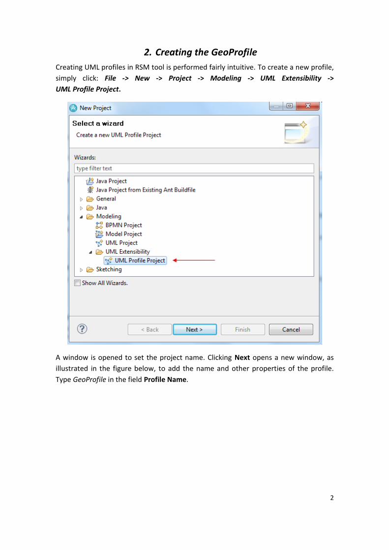
Creating UML profiles in RSM tool is performed fairly intuitive. To create a new profile,
simply click: File -> New -> Project -> Modeling -> UML Extensibility ->
UML Profile Project.
A window is opened to set the project name. Clicking Next opens a new window, as
illustrated in the figure below, to add the name and other properties of the profile.
Type GeoProfile in the field Profile Name.

3
Then, simply click Finish, and the project profile will be created and available for
manipulation in the “Project Explorer”.
4
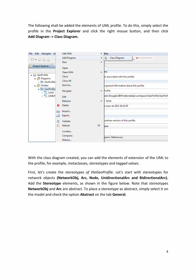
The following shall be added the elements of UML profile. To do this, simply select the
profile in the Project Explorer and click the right mouse button, and then click
Add Diagram -> Class Diagram.
With the class diagram created, you can add the elements of extension of the UML to
the profile, for example, metaclasses, stereotypes and tagged values.
First, let's create the stereotypes of theGeoProfile. Let's start with stereotypes for
network objects (NetworkObj, Arc, Node, UnidirectionalArc and BidirectionalArc).
Add the Stereotype elements, as shown in the figure below. Note that stereotypes
NetworkObj and Arc are abstract. To place a stereotype as abstract, simply select it on
the model and check the option Abstract on the tab General.

5
Then use the element Generalization, so leave the profile as shown below.
The next step is to extend the UML metaclass Class using stereotypes created, to add
the element Metaclass, in the window that appears, select the metaclass Class, add to
the project and click OK.

6
The metaclass "Class" will appear in the diagram, now let's extend the metaclass using
the stereotype created, and just use the element Extension.
Now let's extend the metaclass Association, creating stereotypes that deals with the
topological relationships between the classes. There are six different types of
topological relationships in GeoProfile, let's create just one for example.
First, create an element Stereotype and give it the name "Temporal". Now includes an
element Metaclass, but this time select the metaclass Association and then use the
7
element Extension to extend the metaclass Association with the stereotype created,
as shown in the figure below.
A stereotype can have properties, which can be referred to as tag definitions. When a
stereotype is applied to a model element, the values of the properties are listed in the
profile as tagged values, and can be handled in the model.
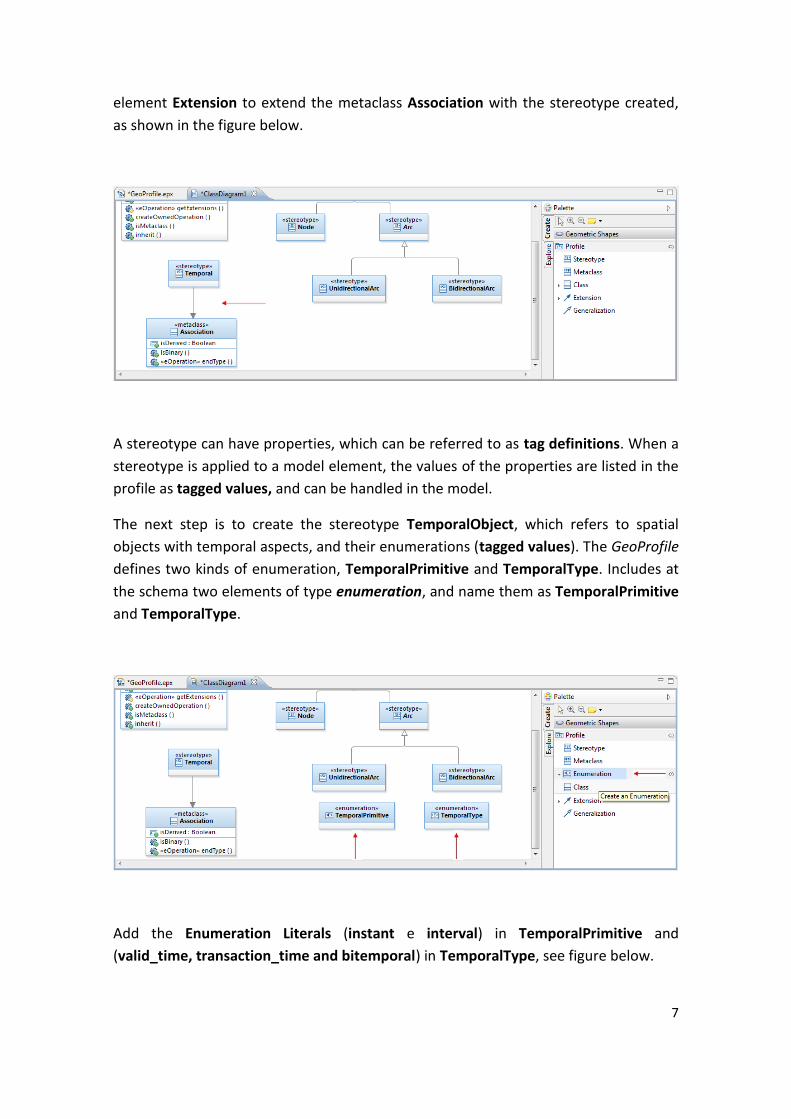
The next step is to create the stereotype TemporalObject, which refers to spatial
objects with temporal aspects, and their enumerations (tagged values). The GeoProfile
defines two kinds of enumeration, TemporalPrimitive and TemporalType. Includes at
the schema two elements of type enumeration, and name them as TemporalPrimitive
and TemporalType.
Add the Enumeration Literals (instant e interval) in TemporalPrimitive and
(valid_time, transaction_time and bitemporal) in TemporalType, see figure below.

8
Now, add to the schema the stereotype TemporalObj and includes two attributes with
types of enumerations created previously: temporalPrimitive of type
TemporalPrimitive and temporalType of type TemporalType.
To add the type of the attribute, just select it within the stereotype or in
Project Explorer tab, and in lower bar General click the Select Type button and select
the type in the window that appears, see figure below.

9
Just now we extend the metaclass Class again for the stereotype created; includes one
more Extension element from the stereotype TemporalObj to the metaclass Class.
This is enough to create the diagram of the profile to stereotypes of GeoProfile entirely
according to your specification; include other Stereotypes, Generalizations and
Extensions that are missing to leave the template as follows. Now, save the template.
Schema of GeoProfile

10
3. Applying OCL Constraints
The RSM supports OCL language for defining constraints, the same used to validate the
generated conceptual schema. This way, OCL constraints described in this section
always have as context a stereotype of GeoProfile, besides being invariant.
The constraints specified for GeoProfile basically avoiding the occurrence of three
types of errors: adding stereotypes incompatible within a single element; poor
construction of networks; and addition of topological relationships are impossible to
happen between two elements (e.g. Cross-relationship between two objects with
representation of geographic point). These three groups of constraints are analysed
below.
To declare Constraints, first right-click the stereotype to which to apply the constraint,
and, on the menu, choose Add UML -> Constraint.
In the edit box that appears, add the OCL constraint refers to the stereotype.
11
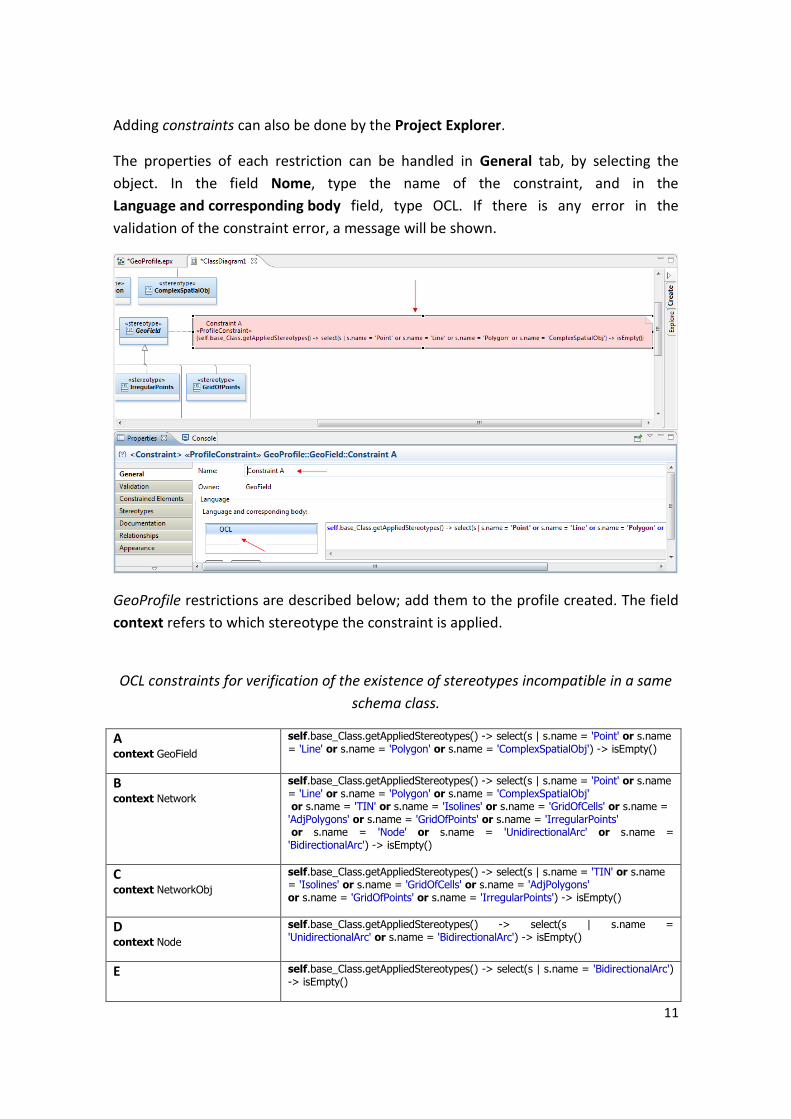
Adding constraints can also be done by the Project Explorer.
The properties of each restriction can be handled in General tab, by selecting the
object. In the field Nome, type the name of the constraint, and in the
Language and corresponding body field, type OCL. If there is any error in the
validation of the constraint error, a message will be shown.
GeoProfile restrictions are described below; add them to the profile created. The field
context refers to which stereotype the constraint is applied.
OCL constraints for verification of the existence of stereotypes incompatible in a same
schema class.
A context GeoField
self.base_Class.getAppliedStereotypes() -> select(s | s.name = 'Point' or s.name = 'Line' or s.name = 'Polygon' or s.name = 'ComplexSpatialObj') -> isEmpty()
B context Network
self.base_Class.getAppliedStereotypes() -> select(s | s.name = 'Point' or s.name = 'Line' or s.name = 'Polygon' or s.name = 'ComplexSpatialObj' or s.name = 'TIN' or s.name = 'Isolines' or s.name = 'GridOfCells' or s.name = 'AdjPolygons' or s.name = 'GridOfPoints' or s.name = 'IrregularPoints' or s.name = 'Node' or s.name = 'UnidirectionalArc' or s.name = 'BidirectionalArc') -> isEmpty()
C context NetworkObj
self.base_Class.getAppliedStereotypes() -> select(s | s.name = 'TIN' or s.name = 'Isolines' or s.name = 'GridOfCells' or s.name = 'AdjPolygons' or s.name = 'GridOfPoints' or s.name = 'IrregularPoints') -> isEmpty()
D context Node
self.base_Class.getAppliedStereotypes() -> select(s | s.name = 'UnidirectionalArc' or s.name = 'BidirectionalArc') -> isEmpty()
E self.base_Class.getAppliedStereotypes() -> select(s | s.name = 'BidirectionalArc') -> isEmpty()
12
context UnidirectionalArc
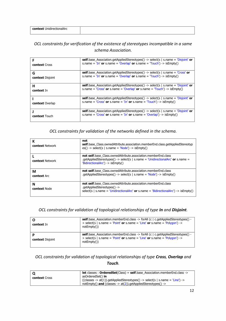
OCL constraints for verification of the existence of stereotypes incompatible in a same
schema Association.
F context Cross
self.base_Association.getAppliedStereotypes() -> select(s | s.name = 'Disjoint' or s.name = 'In' or s.name = 'Overlap' or s.name = 'Touch') -> isEmpty()
G context Disjoint
self.base_Association.getAppliedStereotypes() -> select(s | s.name = 'Cross' or s.name = 'In' or s.name = 'Overlap' or s.name = 'Touch') -> isEmpty()
H context In
self.base_Association.getAppliedStereotypes() -> select(s | s.name = 'Disjoint' or s.name = 'Cross' or s.name = 'Overlap' or s.name = 'Touch') -> isEmpty()
I context Overlap
self.base_Association.getAppliedStereotypes() -> select(s | s.name = 'Disjoint' or s.name = 'Cross' or s.name = 'In' or s.name = 'Touch') -> isEmpty()
J context Touch
self.base_Association.getAppliedStereotypes() -> select(s | s.name = 'Disjoint' or s.name = 'Cross' or s.name = 'In' or s.name = 'Overlap') -> isEmpty()
OCL constraints for validation of the networks defined in the schema.
K context Network
not self.base_Class.ownedAttribute.association.memberEnd.class.getAppliedStereotypes() -> select(s | s.name = 'Node') -> isEmpty()
L context Network
not self.base_Class.ownedAttribute.association.memberEnd.class .getAppliedStereotypes() -> select(s | s.name = 'UnidirectionalArc' or s.name = 'BidirectionalArc') -> isEmpty()
M context Arc
not self.base_Class.ownedAttribute.association.memberEnd.class .getAppliedStereotypes() -> select(s | s.name = 'Node') -> isEmpty()
N context Node
not self.base_Class.ownedAttribute.association.memberEnd.class .getAppliedStereotypes() -> select(s | s.name = 'UnidirectionalArc' or s.name = 'BidirectionalArc') -> isEmpty()
OCL constraints for validation of topological relationships of type In and Disjoint.
O context In
self.base_Association.memberEnd.class -> forAll (c | c.getAppliedStereotypes() -> select(s | s.name = 'Point' or s.name = 'Line' or s.name = 'Polygon') -> notEmpty())
P context Disjoint
self.base_Association.memberEnd.class -> forAll (c | c.getAppliedStereotypes() -> select(s | s.name = 'Point' or s.name = 'Line' or s.name = 'Polygon') -> notEmpty())
OCL constraints for validation of topological relationships of type Cross, Overlap and
Touch.
Q context Cross
let classes : OrderedSet(Class) = self.base_Association.memberEnd.class -> asOrderedSet() in ((classes -> at(1)).getAppliedStereotypes() -> select(s | s.name = 'Line') -> notEmpty() and (classes -> at(2)).getAppliedStereotypes() ->

13
select(s | s.name = 'Line') -> notEmpty() ) or ((classes -> at(1)).getAppliedStereotypes() -> select(s | s.name = 'Line') -> notEmpty() and (classes -> at(2)).getAppliedStereotypes() -> select(s | s.name = 'Polygon') -> notEmpty() ) or ((classes -> at(1)).getAppliedStereotypes() -> select(s | s.name = 'Polygon') -> notEmpty() and (classes -> at(2)).getAppliedStereotypes() -> select(s | s.name = 'Line') -> notEmpty() )
R context Overlap
let classes : OrderedSet(Class) = self.base_Association.memberEnd.class -> asOrderedSet() in ((classes -> at(1)).getAppliedStereotypes() -> select(s | s.name = 'Line') -> notEmpty() and (classes -> at(2)).getAppliedStereotypes() -> select(s | s.name = 'Line') -> notEmpty() ) or ((classes -> at(1)).getAppliedStereotypes() -> select(s | s.name = 'Polygon') -> notEmpty() and (classes -> at(2)).getAppliedStereotypes() -> select(s | s.name = 'Polygon') -> notEmpty() )
S context Touch
let classes : OrderedSet(Class) = self.base_Association.memberEnd.class -> asOrderedSet() in ((classes -> at(1)).getAppliedStereotypes() -> select(s | s.name = 'Polygon') -> notEmpty() and (classes -> at(2)).getAppliedStereotypes() -> select(s | s.name = 'Polygon') -> notEmpty() ) or ((classes -> at(1)).getAppliedStereotypes() -> select(s | s.name = 'Line') -> notEmpty() and (classes -> at(2)).getAppliedStereotypes() -> select(s | s.name = 'Line') -> notEmpty() ) or ((classes -> at(1)).getAppliedStereotypes() -> select(s | s.name = 'Line') -> notEmpty() and (classes -> at(2)).getAppliedStereotypes() -> select(s | s.name = 'Polygon') -> notEmpty() ) or ((classes -> at(1)).getAppliedStereotypes() -> select(s | s.name = 'Polygon') -> notEmpty() and (classes -> at(2)).getAppliedStereotypes() -> select(s | s.name = 'Line') -> notEmpty() ) or ((classes -> at(1)).getAppliedStereotypes() -> select(s | s.name = 'Point') -> notEmpty() and (classes -> at(2)).getAppliedStereotypes() -> select(s | s.name = 'Polygon') -> notEmpty() ) or ((classes -> at(1)).getAppliedStereotypes() -> select(s | s.name = 'Polygon') -> notEmpty() and (classes -> at(2)).getAppliedStereotypes() -> select(s | s.name = 'Point') -> notEmpty() ) or ((classes -> at(1)).getAppliedStereotypes() -> select(s | s.name = 'Point') -> notEmpty() and (classes -> at(2)).getAppliedStereotypes() -> select(s | s.name = 'Line') -> notEmpty() ) or ((classes -> at(1)).getAppliedStereotypes() -> select(s | s.name = 'Line') -> notEmpty() and (classes -> at(2)).getAppliedStereotypes() -> select(s | s.name = 'Point') -> notEmpty() )
Recalling that the OCL constraints of the GeoProfile validate only the conceptual
schema; is valid to say that a topological relationship modeled between classes that
have multiple representation is conceptually correct if the type of topological
relationship can exist for at least one geographical representation of the classes
concerned. In this case, the application has to restrict which geographical
representation of the class will be involved in the relationship.
14
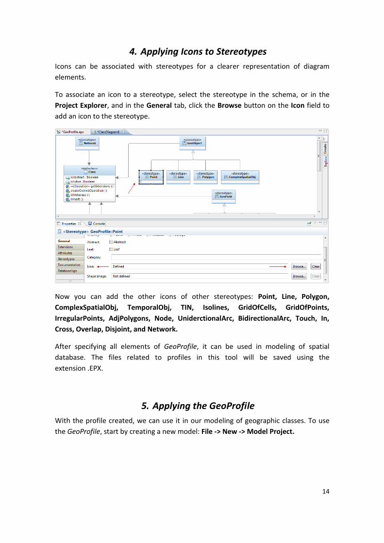
4. Applying Icons to Stereotypes
Icons can be associated with stereotypes for a clearer representation of diagram
elements.
To associate an icon to a stereotype, select the stereotype in the schema, or in the
Project Explorer, and in the General tab, click the Browse button on the Icon field to
add an icon to the stereotype.
Now you can add the other icons of other stereotypes: Point, Line, Polygon,
ComplexSpatialObj, TemporalObj, TIN, Isolines, GridOfCells, GridOfPoints,
IrregularPoints, AdjPolygons, Node, UniderctionalArc, BidirectionalArc, Touch, In,
Cross, Overlap, Disjoint, and Network.
After specifying all elements of GeoProfile, it can be used in modeling of spatial
database. The files related to profiles in this tool will be saved using the
extension .EPX.
5. Applying the GeoProfile
With the profile created, we can use it in our modeling of geographic classes. To use
the GeoProfile, start by creating a new model: File -> New -> Model Project.
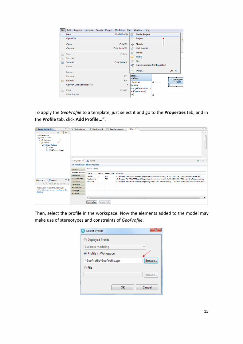
15
To apply the GeoProfile to a template, just select it and go to the Properties tab, and in
the Profile tab, click Add Profile...”.
Then, select the profile in the workspace. Now the elements added to the model may
make use of stereotypes and constraints of GeoProfile.

16
Now, with the profile applied, you can apply the stereotypes of GeoProfile in UML
elements. For example, to include a class in the model, simply go to the Properties tab,
click Stereotypes and then “Apply Stereotypes...”. A window will be opened with all
the available stereotypes.
Now, select the stereotype you want and click OK. The stereotype is then applied to
the corresponding class.
Note: you can apply more than one stereotype to a same class, the OCL constraints
described above prevent incompatible stereotypes are applied in the same class.

17
With the stereotype applied to the class, you can change some properties, such as the
way you view the same. The tool provides several ways to view stereotypes:
Decoração e Texto, Decoração, Imagem da Forma, Texto e Nenhum. To accomplish
this, simply select the class, right-click it, and then click: Filters -> Stereotypes and
Visibility Style, and then select the desired shape.
Note: there are occurrences of problems when viewing more than one stereotype by class. If are applied more than one stereotype to a class, can only be viewed the icon of the first stereotype applied. To work around this problem, you should opt for the visualization of stereotypes in textual form or text and icon.
As defined in GeoProfile, stereotypes can also be applied to relationships. Add another class with a stereotype and an Association element between them.

18
Select the object Association added and add a stereotype to proceed in the same way
as shown for objects of type class.
Another type of geographical object that can be found in our applications are the
temporal objects, defined in GeoProfile as TemporalObj. For this type of object are
defined two tagged values, temporalType and temporalPrimitive. To define their
values, first we should add a class in the model with the stereotype TemporalObj.
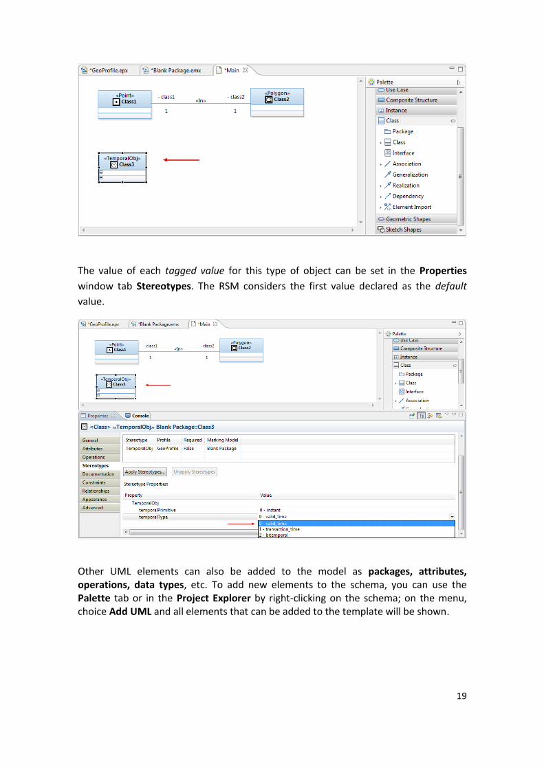
19
The value of each tagged value for this type of object can be set in the Properties
window tab Stereotypes. The RSM considers the first value declared as the default
value.
Other UML elements can also be added to the model as packages, attributes, operations, data types, etc. To add new elements to the schema, you can use the Palette tab or in the Project Explorer by right-clicking on the schema; on the menu, choice Add UML and all elements that can be added to the template will be shown.

20
This is enough to create a complete UML model for modeling spatial database using
GeoProfile in the RSM tool. An example of "School" by using this profile is shown
below.
Note that the classes City, School and District have stereotypes such as <<Point>> and <<polygon>>, it shows how the class may be represented in a geographic application. Disctrict, for example, can be represented as a point or a polygon, depending on the scale. The class Student, in turn, has not stereotype, because it is a class without

21
geographic representation will thus be created as a common object class, without applying any stereotype. Note also that were applied stereotypes to relationships NARY. The stereotype <<in>> between District and City topologically shows that every District element is within a City element, the same goes for the relationship between School and District. There is no topological relationship between Student and School, so we use only one common relationship Association, without applying any stereotype. The next step now is to validate our model using OCL constraints of GeoProfile. To do
this, right-click on the model in the Project Explorer and, on the menu, click Validate.
If any validation error occurs, an error message will appear in the Problems tab.
Otherwise, the confirmation of validation will appear on the Console tab.
22
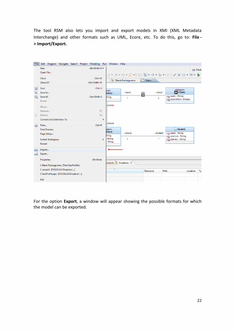
The tool RSM also lets you import and export models in XMI (XML Metadata
Interchange) and other formats such as UML, Ecore, etc. To do this, go to: File -
> Import/Export.
For the option Export, a window will appear showing the possible formats for which the model can be exported.

23
More information about this tool can be found at:
http://www.ibm.com/developerworks/rational/products/rsm/