©1998, 1999, 2000 rational software - all rights reserved session vm08 structuring your rational...
Post on 19-Dec-2015
219 views
TRANSCRIPT

Click on the desired colorClick on the desired color
Helpful tip: Double click the paintbrush tool to applycolor to more than oneobject at a time.
Helpful tip: Double click the paintbrush tool to applycolor to more than oneobject at a time.
ObjectivesObjectives After this presentation you will understand:
Why organize a Rational Rose model using RUP? Using the RUP framework to create a Rational Rose model RUP structure for a Rational Rose model Sequence of UML diagram creation
After this presentation you will understand: Why organize a Rational Rose model using RUP? Using the RUP framework to create a Rational Rose model RUP structure for a Rational Rose model Sequence of UML diagram creation
Click on the desired colorClick on the desired color
Helpful tip: Double click the paintbrush tool to applycolor to more than oneobject at a time.
Helpful tip: Double click the paintbrush tool to applycolor to more than oneobject at a time.
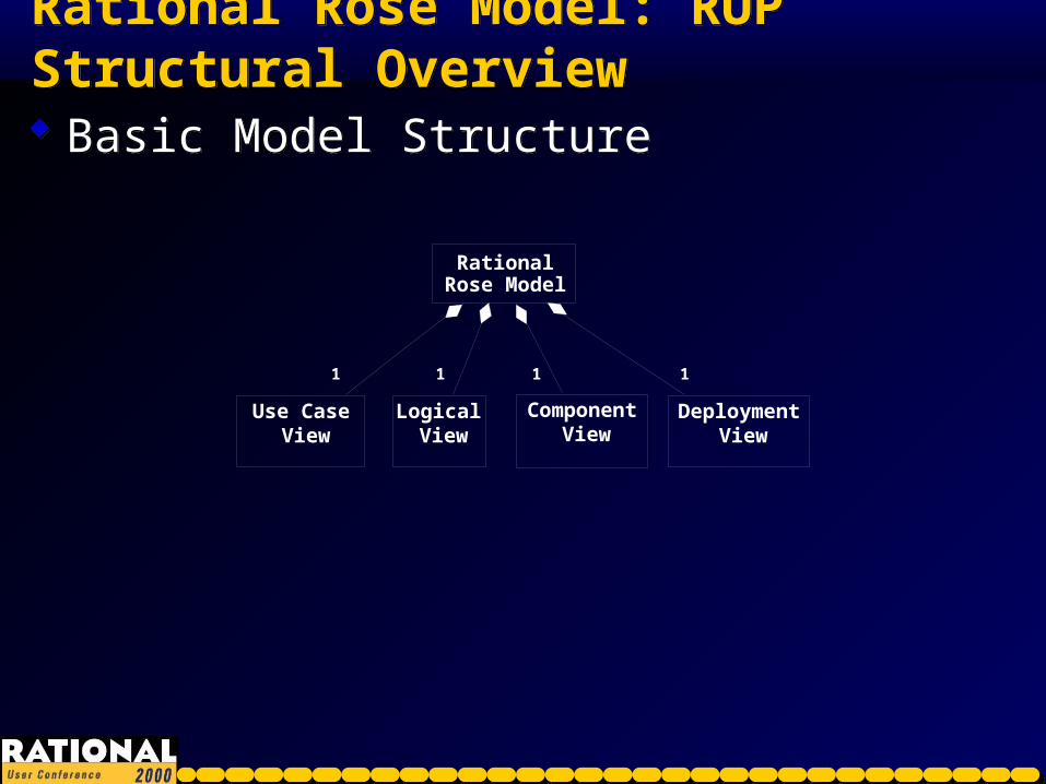
Rational Rose Model: RUP Structural OverviewRational Rose Model: RUP Structural Overview
Basic Model Structure Basic Model Structure
Use Case View
Logical View
Component View
Rational Rose Model
Deployment View
1 1 1 1
Click on the desired colorClick on the desired color
Helpful tip: Double click the paintbrush tool to applycolor to more than oneobject at a time.
Helpful tip: Double click the paintbrush tool to applycolor to more than oneobject at a time.
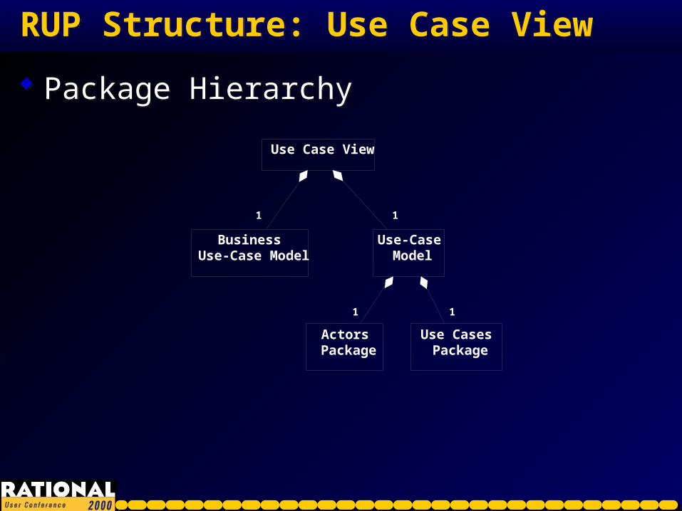
RUP Structure: Use Case ViewRUP Structure: Use Case View
Package Hierarchy Package Hierarchy
Business Use-Case Model
Use Case View
Actors Package
Use-Case Model
Use Cases Package
1 1
1 1

Click on the desired colorClick on the desired color
Helpful tip: Double click the paintbrush tool to applycolor to more than oneobject at a time.
Helpful tip: Double click the paintbrush tool to applycolor to more than oneobject at a time.
Use Case View: Use-Case ModelUse Case View: Use-Case Model
Recommended diagrams Recommended diagramsUse-Case
Model
Actors Package
Actor
0..n0..n
Shows the flow of events for a UC
Activity Diagram
Software Activity
1..n1..n
11
0..n
Use Cases Package
Use Case Diagram
Included UCs Package
0..n0..n
1..n
Specific UC Package
0..n0..n
1..n1..n
Use Case
0..n0..n
11
1 1
Click on the desired colorClick on the desired color
Helpful tip: Double click the paintbrush tool to applycolor to more than oneobject at a time.
Helpful tip: Double click the paintbrush tool to applycolor to more than oneobject at a time.
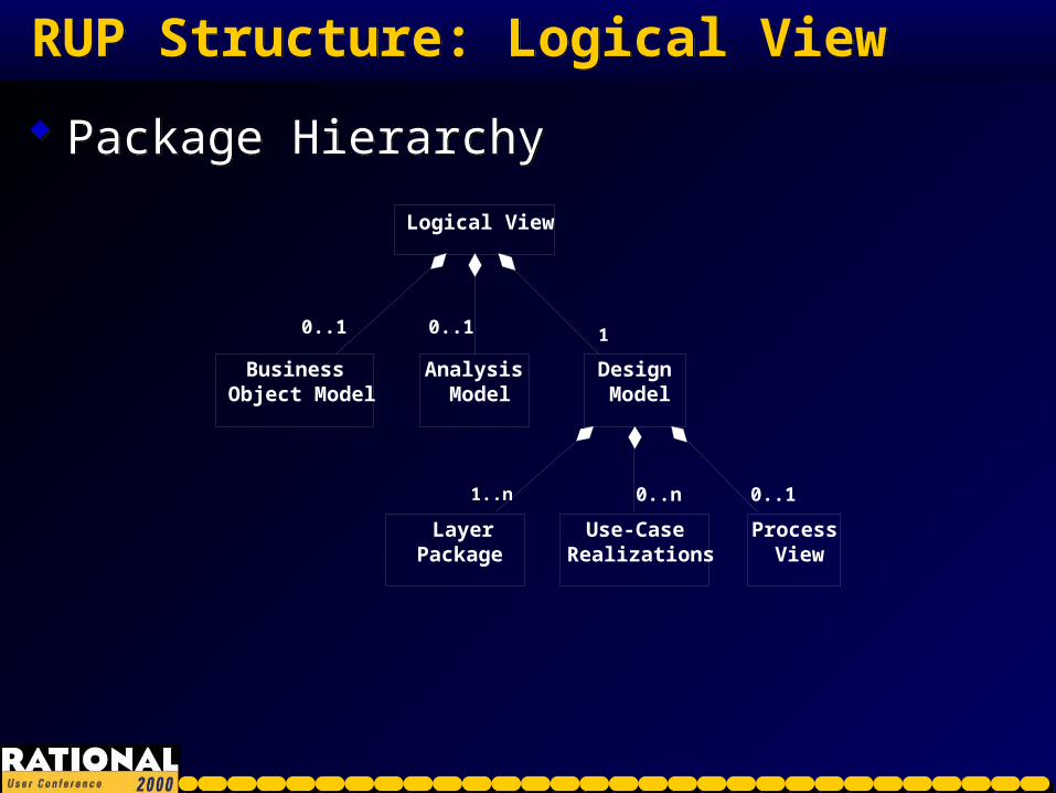
RUP Structure: Logical ViewRUP Structure: Logical View
Package Hierarchy Package Hierarchy
Use-Case Realizations
Business Object Model
Analysis Model
Logical View
Process View
Design Model
LayerPackage
1..n1..n
0..1 10..1
0..10..n

Click on the desired colorClick on the desired color
Helpful tip: Double click the paintbrush tool to applycolor to more than oneobject at a time.
Helpful tip: Double click the paintbrush tool to applycolor to more than oneobject at a time.
Logical View: Analysis Model (optional)Logical View: Analysis Model (optional)
Analysis Model
Class Diagram
1..n
Entity Class
1..n
Boundary Class
0..n0..n
Control Class
0..n0..n
Recommended diagrams Recommended diagrams
Click on the desired colorClick on the desired color
Helpful tip: Double click the paintbrush tool to applycolor to more than oneobject at a time.
Helpful tip: Double click the paintbrush tool to applycolor to more than oneobject at a time.
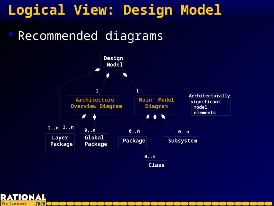
Logical View: Design ModelLogical View: Design Model
Recommended diagrams Recommended diagrams
Design Model
Layer Package
1..n
Architecture Overview Diagram
11
1..n1..n
Global Package
0..n
Class
Package
"Main" Model Diagram
11
0..n
0..n
Subsystem
0..n0..n
0..n
0..n
Architecturally significant model elements
Click on the desired colorClick on the desired color
Helpful tip: Double click the paintbrush tool to applycolor to more than oneobject at a time.
Helpful tip: Double click the paintbrush tool to applycolor to more than oneobject at a time.
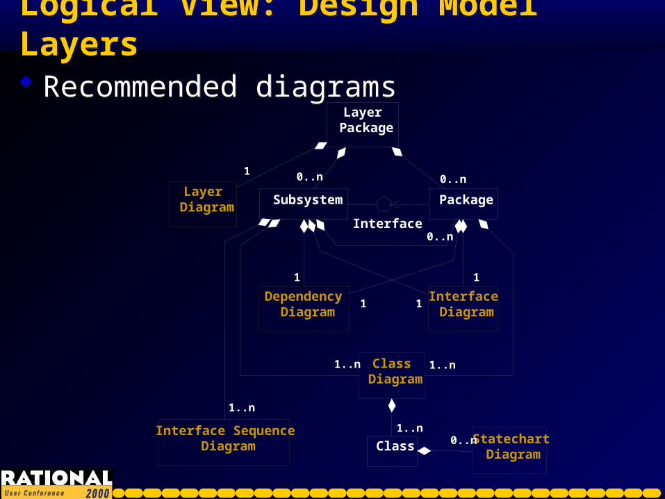
Logical View: Design Model LayersLogical View: Design Model Layers
Recommended diagrams Recommended diagrams
Interface
Layer Diagram
Interface Diagram
Dependency Diagram
Layer Package
11
Package
0..n0..n
11
11
Class Diagram
1..n1..n
Class
1..n1..nStatechart Diagram
0..n0..n
Subsystem
0..n0..n
0..n0..n
11
11
1..n1..n
Interface Sequence Diagram
1..n1..n

Click on the desired colorClick on the desired color
Helpful tip: Double click the paintbrush tool to applycolor to more than oneobject at a time.
Helpful tip: Double click the paintbrush tool to applycolor to more than oneobject at a time.
Logical View: Design Model: UC RealizationsLogical View: Design Model: UC Realizations
Recommended diagrams Recommended diagramsUse-Case
Realizations
Realization Dependency Diagram
Use-Case Package
1..n
11
via script
VOPC Diagram
Sequence Diagram
Use-Case Realization
1..n1..n
1..n1..n
11 1..n
Collaboration Diagram
1..n1..n 1..n
Click on the desired colorClick on the desired color
Helpful tip: Double click the paintbrush tool to applycolor to more than oneobject at a time.
Helpful tip: Double click the paintbrush tool to applycolor to more than oneobject at a time.
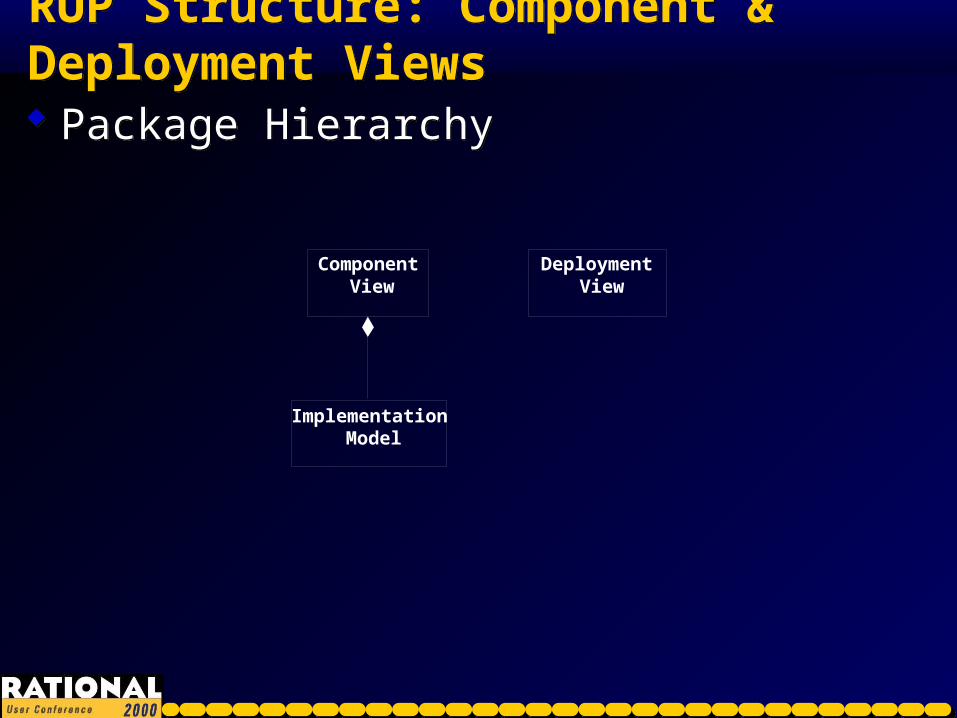
RUP Structure: Component & Deployment ViewsRUP Structure: Component & Deployment Views
Package Hierarchy Package Hierarchy
Component View
Implementation Model
Deployment View
Click on the desired colorClick on the desired color
Helpful tip: Double click the paintbrush tool to applycolor to more than oneobject at a time.
Helpful tip: Double click the paintbrush tool to applycolor to more than oneobject at a time.
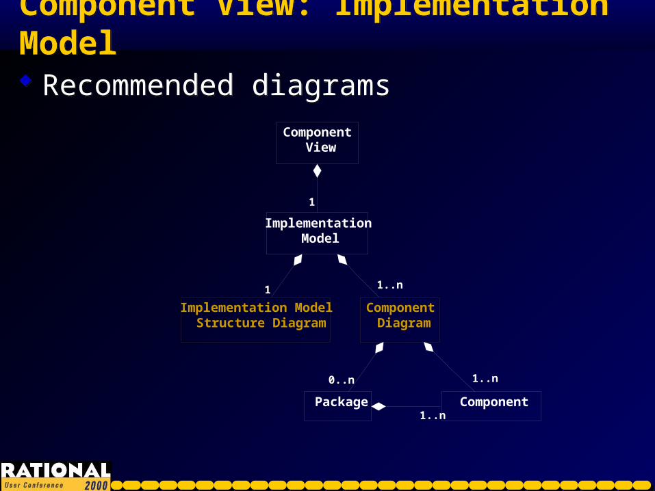
Component View: Implementation ModelComponent View: Implementation Model
Recommended diagrams Recommended diagramsComponent
View
Implementation Model Structure Diagram
Implementation Model
11
11
Package
Component Diagram
1..n1..n
0..n
Component1..n1..n
1..n0..n 1..n
Click on the desired colorClick on the desired color
Helpful tip: Double click the paintbrush tool to applycolor to more than oneobject at a time.
Helpful tip: Double click the paintbrush tool to applycolor to more than oneobject at a time.
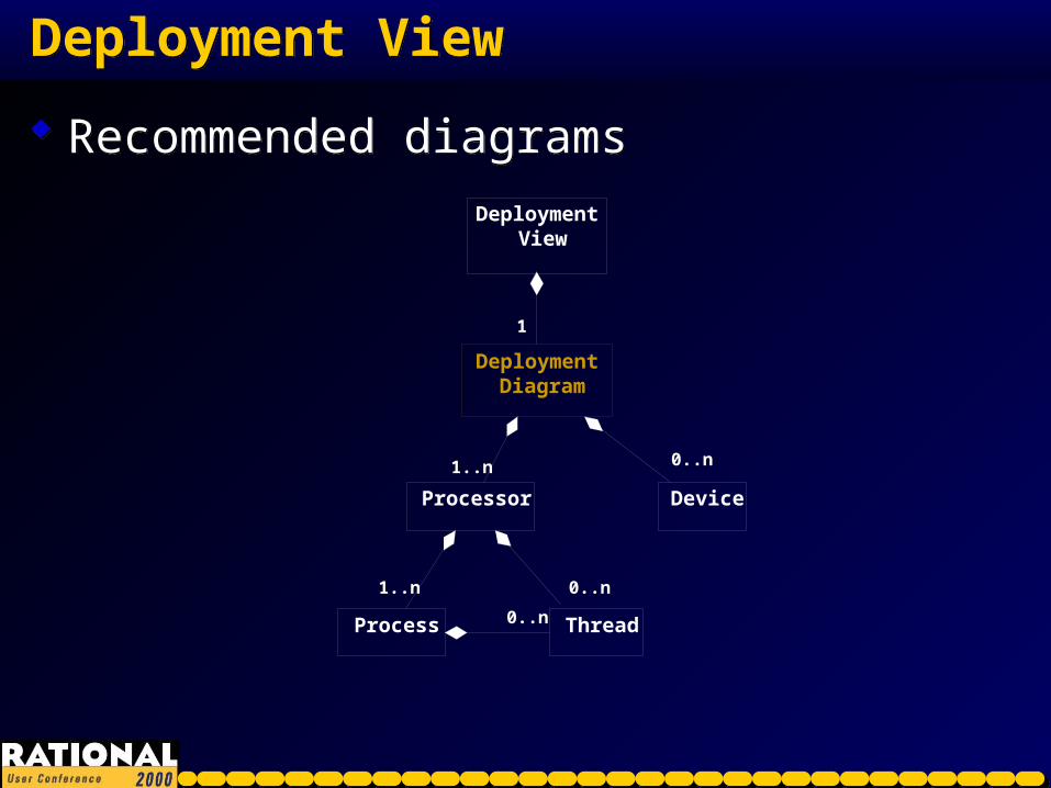
Deployment ViewDeployment View
Recommended diagrams Recommended diagramsDeployment
View
Deployment Diagram
1
Device
0..n0..n
Process
Processor
1..n1..n
1..n
Thread0..n0..n
0..n1..n 0..n

Click on the desired colorClick on the desired color
Helpful tip: Double click the paintbrush tool to applycolor to more than oneobject at a time.
Helpful tip: Double click the paintbrush tool to applycolor to more than oneobject at a time.
ObjectivesObjectives After this presentation you will understand:
Why organize a Rational Rose model using RUP? Using the RUP framework to create a Rational Rose model RUP structure for a Rational Rose model Sequence of UML diagram creation
After this presentation you will understand: Why organize a Rational Rose model using RUP? Using the RUP framework to create a Rational Rose model RUP structure for a Rational Rose model Sequence of UML diagram creation
Click on the desired colorClick on the desired color
Helpful tip: Double click the paintbrush tool to applycolor to more than oneobject at a time.
Helpful tip: Double click the paintbrush tool to applycolor to more than oneobject at a time.
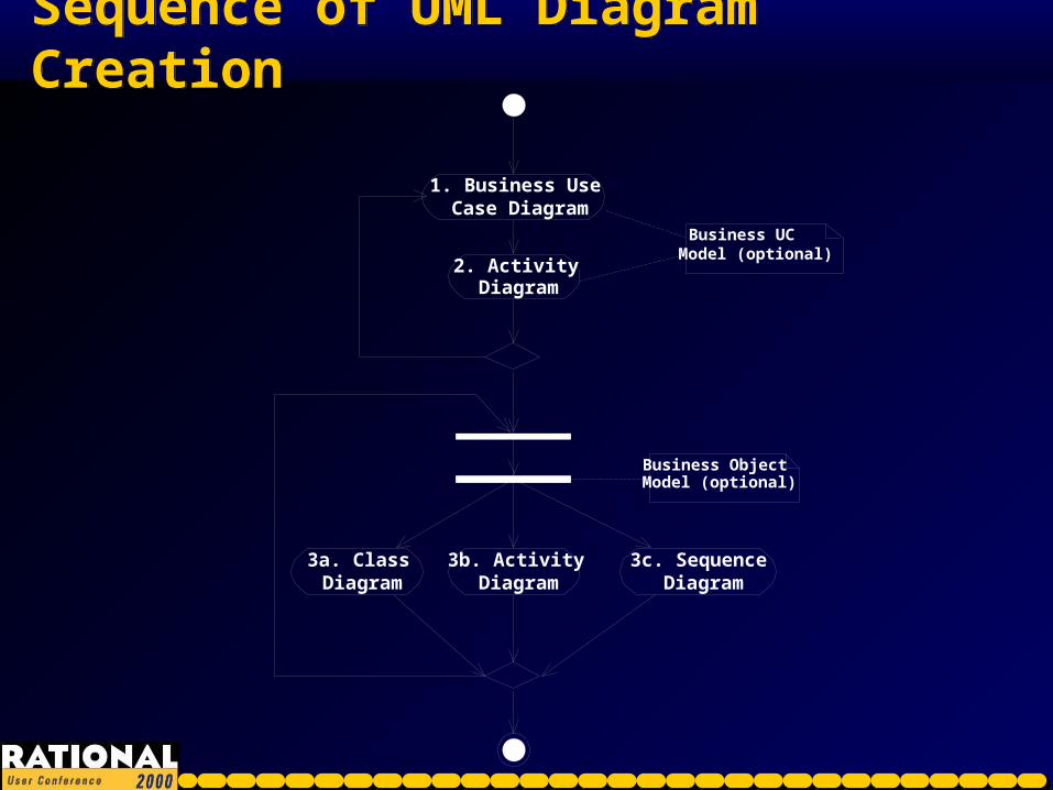
Sequence of UML Diagram CreationSequence of UML Diagram Creation
1. Business Use Case Diagram
2. Activity Diagram
3a. Class Diagram
3b. Activity Diagram
3c. Sequence Diagram
Business Object Model (optional)
Business UC Model (optional)

Click on the desired colorClick on the desired color
Helpful tip: Double click the paintbrush tool to applycolor to more than oneobject at a time.
Helpful tip: Double click the paintbrush tool to applycolor to more than oneobject at a time.
Sequence of UML Diagram Creation (2)Sequence of UML Diagram Creation (2)
4. Use Case Diagram
5. Activity Diagram
Use Case Model
6. Class Diagram
Analysis Model (optional)
Create key abstraction class diagrams in the Design Model if you are skipping the Analysis Model
Click on the desired colorClick on the desired color
Helpful tip: Double click the paintbrush tool to applycolor to more than oneobject at a time.
Helpful tip: Double click the paintbrush tool to applycolor to more than oneobject at a time.
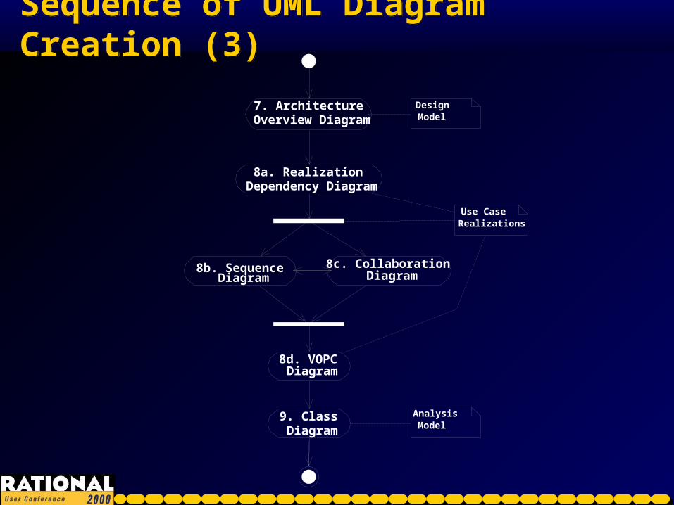
Sequence of UML Diagram Creation (3)Sequence of UML Diagram Creation (3)
7. Architecture Overview Diagram
Design Model
8a. Realization Dependency Diagram
Use Case Realizations
8b. Sequence Diagram
8c. Collaboration Diagram
8d. VOPC Diagram
9. Class Diagram
Analysis Model

Click on the desired colorClick on the desired color
Helpful tip: Double click the paintbrush tool to applycolor to more than oneobject at a time.
Helpful tip: Double click the paintbrush tool to applycolor to more than oneobject at a time.
Sequence of UML Diagram Creation (4)Sequence of UML Diagram Creation (4)
Create subsystem proxies and interfaces
10. "Main" Model Diagram
11a. Layer Diagram
11b. Dependency Diagram
11c. Interface Diagram
Show main elements in a specific layer of the system design
Show classes/ interfaces that are visible outside a package or subsystem
Architecturally significant model elements
All diagram types on this page are in the Design Model
Allocate Analysis classes to specific packages/ subsystems
12. Class Diagram
13. Class Diagram
Click on the desired colorClick on the desired color
Helpful tip: Double click the paintbrush tool to applycolor to more than oneobject at a time.
Helpful tip: Double click the paintbrush tool to applycolor to more than oneobject at a time.
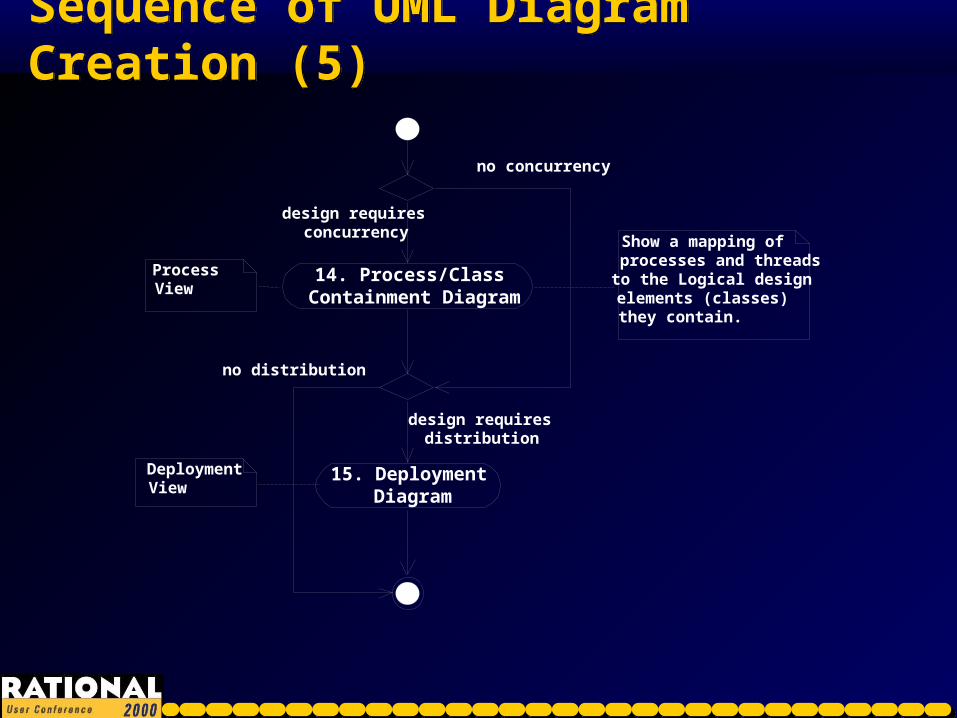
Sequence of UML Diagram Creation (5)Sequence of UML Diagram Creation (5)
14. Process/Class Containment Diagram
design requires concurrency
no concurrency
Show a mapping of processes and threads to the Logical design elements (classes) they contain.
Process View
15. Deployment Diagram
Deployment View
design requires distribution
no distribution

Click on the desired colorClick on the desired color
Helpful tip: Double click the paintbrush tool to applycolor to more than oneobject at a time.
Helpful tip: Double click the paintbrush tool to applycolor to more than oneobject at a time.
Sequence of UML Diagram Creation (6)Sequence of UML Diagram Creation (6)
16a. Sequence Diagram
16b. Collaboration Diagram
Use Case Realizations
Integrate Subsystem interfaces onto UC Realization interaction diagrams
17. Interface Sequence Diagram
18. Class Diagram
19. Statechart Diagram
* Add/refine Operations* Add/refine Attributes* Add/refine Associations* Create additional class diagrams as necessary to illustrate "interesting" design points
For classes with significant “interesting” state-driven behavior
Design Model

Click on the desired colorClick on the desired color
Helpful tip: Double click the paintbrush tool to applycolor to more than oneobject at a time.
Helpful tip: Double click the paintbrush tool to applycolor to more than oneobject at a time.
Sequence of UML Diagram Creation (7)Sequence of UML Diagram Creation (7)
Done! Repeat whole process as necessary
20. Implementation Model Structure Diagram
21. Component Diagram
* Create Components for code to be generated* Map classes from Logical View onto components in Component View * Create Component Diagrams as necessary to illustrate physical layout of code to be generated
Implementation Model
22. Generate Code

Click on the desired colorClick on the desired color
Helpful tip: Double click the paintbrush tool to applycolor to more than oneobject at a time.
Helpful tip: Double click the paintbrush tool to applycolor to more than oneobject at a time.
SummarySummary Improve team efficiency by following the RUP structure
of a Rational Rose model Know where in your Rational Rose model to place the
different recommended UML diagram types Agree on a sequence of UML diagram creation that
works for your project
Improve team efficiency by following the RUP structure of a Rational Rose model
Know where in your Rational Rose model to place the different recommended UML diagram types
Agree on a sequence of UML diagram creation that works for your project
©1998, 1999, 2000 Rational Software - All rights reserved©1998, 1999, 2000 Rational Software - All rights reserved
Session VM08Session VM08
Questions?Questions?

©1998, 1999, 2000 Rational Software - All rights reserved©1998, 1999, 2000 Rational Software - All rights reserved
Session VM08Session VM08
Thank You!Thank You!This presentation will be posted by tomorrow to http://www.rational.com/rucThis presentation will be posted by tomorrow to http://www.rational.com/ruc
Robert Bretall
Rational Software