12 x 35 wood lathe - grizzlycdn4.grizzly.com/manuals/g5979_m.pdf-2- g5979 wood lathe section 1:...
TRANSCRIPT

12" X 351⁄2" WOOD LATHEMODEL G5979
INSTRUCTION MANUAL
COPYRIGHT © FEBRUARY, 2002 BY GRIZZLY INDUSTRIAL, INC. WARNING: NO PORTION OF THIS MANUAL MAY BE REPRODUCED IN ANY SHAPE
OR FORM WITHOUT THE WRITTEN APPROVAL OF GRIZZLY INDUSTRIAL, INC.PRINTED IN CHINA.

WARNINGSome dust created by power sanding, sawing, grind-ing, drilling, and other construction activities containschemicals known to the State of California to causecancer, birth defects or other reproductive harm. Someexamples of these chemicals are:
• Lead from lead-based paints.• Crystalline silica from bricks, cement, and other
masonry products.• Arsenic and chromium from chemically treated
lumber.
Your risk from these exposures varies, depending onhow often you do this type of work. To reduce yourexposure to these chemicals: work in a well ventilatedarea, and work with approved safety equipment, suchas those dust masks that are specially designed to fil-ter out microscopic particles.

Table Of ContentsPAGE
1. SAFETYSAFETY RULES FOR ALL TOOLS......................................................................2-3ADDITIONAL SAFETY INSTRUCTIONS FOR G5979 ............................................4
2. CIRCUIT REQUIREMENTS110V OPERATION ..................................................................................................5GROUNDING ..........................................................................................................5EXTENSION CORDS ..............................................................................................5
3. INTRODUCTIONCOMMENTARY........................................................................................................6UNPACKING ............................................................................................................7PIECE INVENTORY ................................................................................................8HARDWARE RECOGNITION ..................................................................................9CLEAN UP..............................................................................................................10SITE CONSIDERATIONS ......................................................................................10
4. ASSEMBLYBEGINNING ASSEMBLY ......................................................................................11STAND....................................................................................................................11LATHE TO STAND ................................................................................................12FLOOR MOUNTING ..............................................................................................12HEADSTOCK LOCK ..............................................................................................13SPUR CENTER......................................................................................................13FACEPLATE ..........................................................................................................14EXTENSION BED ..................................................................................................14
5. ADJUSTMENTSHEADSTOCK ........................................................................................................15TAILSTOCK............................................................................................................15TOOL REST ..........................................................................................................16
6. OPERATIONSTEST RUN..............................................................................................................17SPEED SELECTOR ..............................................................................................17SPINDLE TURNING ..............................................................................................18FACEPLATE TURNING ........................................................................................19TOOL REST ..........................................................................................................19
7. MAINTENANCEGENERAL ..............................................................................................................20RUST......................................................................................................................20LUBRICATION........................................................................................................20V-BELT ..................................................................................................................20DUST/CHIP REMOVAL..........................................................................................20
8. CLOSURE ....................................................................................................................21
MACHINE DATA ................................................................................................................22PARTS BREAKDOWN AND PARTS LISTS................................................................23-25WARRANTY AND RETURNS ..........................................................................................26

-2- G5979 Wood Lathe
SECTION 1: SAFETY
For Your Own Safety Read InstructionManual Before Operating This Equipment
Indicates an imminently hazardous situation which, if not avoided,WILL result in death or serious injury.
Indicates a potentially hazardous situation which, if not avoided,COULD result in death or serious injury.
Indicates a potentially hazardous situation which, if not avoided,MAY result in minor or moderate injury. It may also be used to alertagainst unsafe practices.
This symbol is used to alert the user to useful information aboutproper operation of the equipment.
The purpose of safety symbols is to attract your attention to possible hazardous conditions. Thismanual uses a series of symbols and signal words which are intended to convey the level ofimportance of the safety messages. The progression of symbols is described below. Rememberthat safety messages by themselves do not eliminate danger and are not a substitute for properaccident prevention measures.
NOTICE
Safety Instructions For Power Tools5. KEEP CHILDREN AND VISITORS
AWAY. All children and visitors should bekept a safe distance from work area.
6. MAKE WORKSHOP CHILD PROOF withpadlocks, master switches, or by removingstarter keys.
7. DO NOT FORCE TOOL. It will do the jobbetter and safer at the rate for which it wasdesigned.
8. USE RIGHT TOOL. Do not force tool orattachment to do a job for which it was notdesigned.
1. KEEP GUARDS IN PLACE and in workingorder.
2. REMOVE ADJUSTING KEYS ANDWRENCHES. Form habit of checking tosee that keys and adjusting wrenches areremoved from tool before turning on.
3. KEEP WORK AREA CLEAN. Clutteredareas and benches invite accidents.
4. DO NOT USE IN DANGEROUS ENVI-RONMENT. Do not use power tools indamp or wet locations, or where any flam-mable or noxious fumes may exist. Keepwork area well lighted.

G5979 Wood Lathe -3-
9. USE PROPER EXTENSION CORD. Makesure your extension cord is in good condi-tion. Conductor size should be in accor-dance with the chart below. The amperagerating should be listed on the motor or toolnameplate. An undersized cord will causea drop in line voltage resulting in loss ofpower and overheating. Your extensioncord must also contain a ground wire andplug pin. Always repair or replace exten-sion cords if they become damaged.
Minimum Gauge for Extension Cords
10. WEAR PROPER APPAREL. Do not wearloose clothing, gloves, neckties, rings,bracelets, or other jewelry which may getcaught in moving parts. Non-slip footwearis recommended. Wear protective hair cov-ering to contain long hair.
11. ALWAYS USE SAFETY GLASSES. Alsouse face or dust mask if cutting operation isdusty. Everyday eyeglasses only have impactresistant lenses, they are NOT safety glasses.
12. SECURE WORK. Use clamps or a vise to holdwork when practical. It’s safer than using yourhand and frees both hands to operate tool.
13. DO NOT OVER-REACH. Keep properfooting and balance at all times.
14. MAINTAIN TOOLS WITH CARE. Keeptools sharp and clean for best and safestperformance. Follow instructions for lubri-cating and changing accessories.
15. USE RECOMMENDED ACCESSORIES.Consult the owner’s manual for recom-mended accessories. The use of improperaccessories may cause risk of injury.
LENGTHAMP RATING 25ft 50ft 100ft
0-6 18 16 167-10 18 16 1411-12 16 16 1413-16 14 12 1217-20 12 12 1021-30 10 10 No
Safety Instructions For Power Tools16. REDUCE THE RISK OF UNINTENTION-
AL STARTING. On machines with magnet-ic contact starting switches there is a risk ofstarting if the machine is bumped or jarred.Always disconnect from power sourcebefore adjusting or servicing. Make sureswitch is in OFF position before reconnecting.
17. MANY WOODWORKING TOOLS CAN“KICKBACK” THE WORKPIECE toward theoperator if not handled properly. Know whatconditions can create “kickback” and knowhow to avoid them. Read the manual accom-panying the machine thoroughly.
18. CHECK DAMAGED PARTS. Before fur-ther use of the tool, a guard or other partthat is damaged should be carefullychecked to determine that it will operateproperly and perform its intended function.Check for alignment of moving parts, bind-ing of moving parts, breakage of parts,mounting, and any other conditions thatmay affect its operation. A guard or otherpart that is damaged should be properlyrepaired or replaced.
19. NEVER LEAVE TOOL RUNNING UNAT-TENDED. TURN POWER OFF. Do notleave tool until it comes to a complete stop.
20. NEVER OPERATE A MACHINE WHENTIRED, OR UNDER THE INFLUENCE OFDRUGS OR ALCOHOL. Full mental alert-ness is required at all times when running amachine.
21. NEVER ALLOW UNSUPERVISED ORUNTRAINED PERSONNEL TO OPER-ATE THE MACHINE. Make sure anyinstructions you give in regards to machineoperation are approved, correct, safe, andclearly understood.
22. IF AT ANY TIME YOU ARE EXPERIENC-ING DIFFICULTIES performing the intend-ed operation, stop using the machine! Thencontact our service department or ask aqualified expert how the operation shouldbe performed.

-4- G5979 Wood Lathe
No list of safety guidelines can be complete.Every shop environment is different. Alwaysconsider safety first, as it applies to yourindividual working conditions. Use this andother machinery with caution and respect.Failure to do so could result in serious per-sonal injury, damage to equipment or poorwork results.
Additional Safety Instructions For The Lathe1. MAKE SURE ALL GUARDS are in place
and that the Lathe sits on a flat, stable sur-face.
2. ALWAYS WEAR EYE PROTECTION or aface shield when operating the Lathe. Allsafety equipment should be ANSI approved.
3. USE A RESPIRATOR TO AVOID INHAIL-ING DUST. All safety equipment should beANSI approved.
4. BEFORE STARTING THE MACHINE becertain the workpiece has been properlyimbedded on the headstock and tailstockcenters and that there is adequate clearancefor the full rotation.
5. ADJUST TOOL REST to provide propersupport for the turning tool you will be using.Test tool rest clearance by rotating work-piece by hand before turning lathe on.
6. SELECT THE TURNING SPEED which isappropriate for the type of work. Allow thelathe to gain its full speed before using.
7. ALWAYS INSPECT THE CONDITION ofthe materials you are turning. Do not turnpieces with knots, splits and other potential-ly dangerous conditions.
8. KEEP LATHE TOOLS PROPERLYSHARPENED and hold firmly in the properposition when turning.
9. NEVER OPERATE THE LATHE WITHDAMAGED OR WORN PARTS. Maintainyour lathe in proper working condition.Perform routine inspections and mainte-nance promptly when called for. Put awayadjustment tools after use.
10. MAKE SURE YOUR WOOD LATHE ISTURNED OFF, disconnected from its powersource and all moving parts have come to acomplete stop before starting any inspec-tion, adjustment, or maintenance procedure.
11. DO NOT LEAVE LATHE RUNNING UNAT-TENDED for any reason.
12. DO NOT STOP LATHE USING YOURHAND against the workpiece.
13. KEEP LOOSE CLOTHING ARTICLESsuch as sleeves, belts and jewelry itemsaway from the lathe spindle.
14. WHEN FACE PLATE TURNING, use lathechisels on the downward spinning side ofthe workpiece only.
15. REMOVE THE TOOL REST when perform-ing sanding or polishing operations on therotating spindle.
16. ATTEMPTING TO REMOVE too muchmaterial at once may cause work material tofly out of the lathe.
G5979 Wood Lathe -5-
110V Operation
SECTION 2: CIRCUIT REQUIREMENTS
A 15 amp dedicated circuit should be used withthis wood lathe. Always check to see if your cur-rent wires are capable of handling a 4 amp load.If you are unsure, consult the advice of a qualifiedelectrician.
If you find it necessary to use an extension cordwith the Model G5979, make sure the cord israted Hard Service (grade S) or better. Refer tothe chart in the standard safety instructions todetermine the minimum gauge for the extensioncord. The extension cord must also contain aground wire and plug pin. Always repair or replaceextension cords when they become worn or dam-aged.
Extension Cords
Grounding
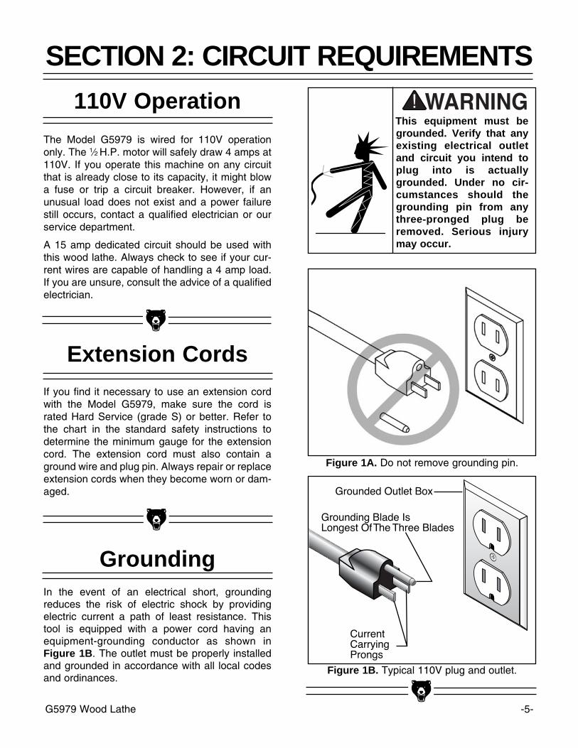
This equipment must begrounded. Verify that anyexisting electrical outletand circuit you intend toplug into is actuallygrounded. Under no cir-cumstances should thegrounding pin from anythree-pronged plug beremoved. Serious injurymay occur.
In the event of an electrical short, groundingreduces the risk of electric shock by providingelectric current a path of least resistance. Thistool is equipped with a power cord having anequipment-grounding conductor as shown inFigure 1B. The outlet must be properly installedand grounded in accordance with all local codesand ordinances.
The Model G5979 is wired for 110V operationonly. The 1⁄2 H.P. motor will safely draw 4 amps at110V. If you operate this machine on any circuitthat is already close to its capacity, it might blowa fuse or trip a circuit breaker. However, if anunusual load does not exist and a power failurestill occurs, contact a qualified electrician or ourservice department.
Figure 1B. Typical 110V plug and outlet.
Figure 1A. Do not remove grounding pin.

-6- G5979 Wood Lathe
SECTION 3: INTRODUCTION
We are proud to offer the Grizzly Model G5979Wood Lathe. The Model G5979 is part of a grow-ing Grizzly family of fine woodworking machinery.When used according to the guidelines set forth inthis manual, you can expect years of trouble-free,enjoyable operation and proof of Grizzly’s com-mitment to customer satisfaction.
The Model G5979 is a 10 speed, swivel-headwood lathe capable of a wide variety of turningoperations. This lathe also features a cast ironbed, outboard tool rest, quick-release head andtailstock, 12" swing over bed, 351⁄2" between cen-ters, 6" faceplate and #2 Morse Taper.
A number of chisels, gouges, faceplates andaccessories for the Model G5979 are availablethrough the Grizzly catalog.
We are also pleased to provide this manual withthe Model G5979. It was written to guide youthrough assembly, review safety considerations,and cover general operating procedures. It repre-sents our effort to produce the best documenta-tion possible. If you have any comments regard-ing this manual, please write to us at the addressbelow:
Grizzly Industrial, Inc.C/O Technical Documentation
P.O. Box 2069Bellingham, WA 98227-2069
Most importantly, we stand behind our machines.If you have any service questions or partsrequests, please call or write us at the locationlisted below.
Grizzly Industrial, Inc.1203 Lycoming Mall Circle
Muncy, PA 17756Phone: (570) 546-9663
Fax: (800) 438-5901E-Mail: [email protected] Site: http://www.grizzly.com
The specifications, drawings, and photographsillustrated in this manual represent the ModelG5979 as supplied when the manual was pre-pared. However, owing to Grizzly’s policy of con-tinuous improvement, changes may be made atany time with no obligation on the part of Grizzly.Whenever possible, though, we send manualupdates to all owners of a particular tool ormachine. Should you receive one, we urge you toinsert the new information with the old and keep itfor reference.
Commentary
Read the manual beforeassembly and opera-tion. Become familiarwith the machine and itsoperation before begin-ning any work. Seriouspersonal injury mayresult if safety or opera-tional information is notunderstood or followed.

G5979 Wood Lathe -7-
Unpacking
If moving this machineup or down stairs, themachine must be dis-mantled and moved insmaller pieces. Makesure floor and stairstructures are capable ofsupporting the com-bined weight of themachine parts and thepeople moving them.
The Model G5979 is shipped from the manufac-turer in a carefully packed carton. If you discoverthe machine is damaged after you’ve signed fordelivery, immediately call Customer Service foradvice.
When you are completely satisfied with the con-dition of your shipment, you should inventory itsparts in the next section.
The G5979 represents aload of 190 pounds.Seek assistance beforebeginning assembly.
Some metal parts mayhave sharp edges onthem after they areformed. Please examinethe edges of all metalparts before handlingthem. Failure to do socould result in injury.
-8- G5979 Wood Lathe
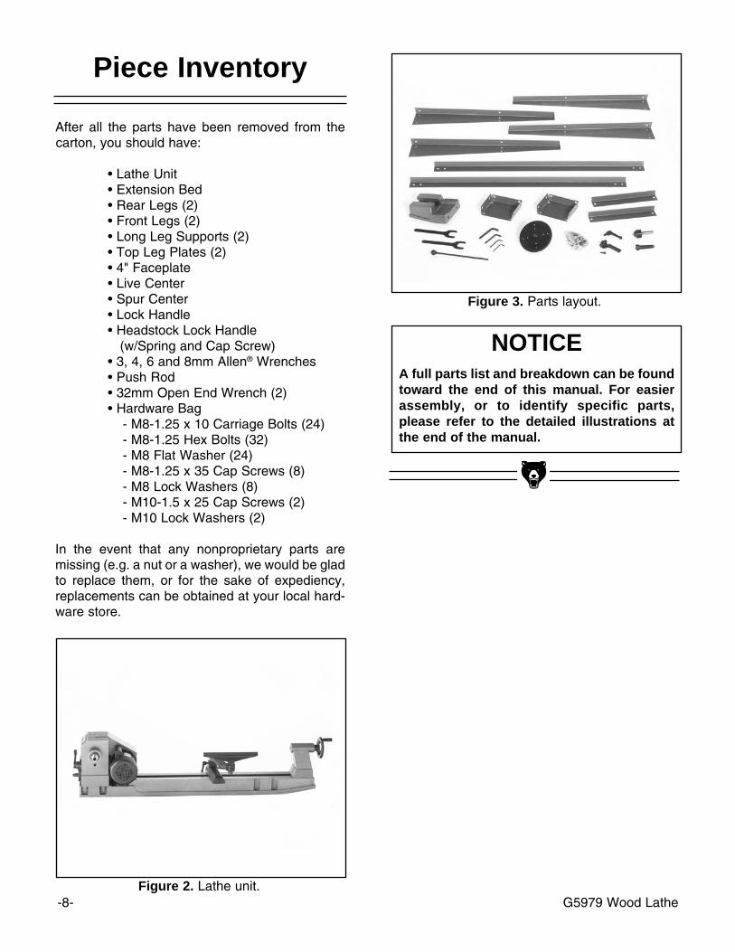
NOTICEA full parts list and breakdown can be foundtoward the end of this manual. For easierassembly, or to identify specific parts,please refer to the detailed illustrations atthe end of the manual.
Figure 3. Parts layout.
Piece Inventory
After all the parts have been removed from thecarton, you should have:
• Lathe Unit• Extension Bed• Rear Legs (2)• Front Legs (2)• Long Leg Supports (2)• Top Leg Plates (2)• 4" Faceplate• Live Center• Spur Center• Lock Handle• Headstock Lock Handle
(w/Spring and Cap Screw)• 3, 4, 6 and 8mm Allen® Wrenches• Push Rod• 32mm Open End Wrench (2)• Hardware Bag
- M8-1.25 x 10 Carriage Bolts (24)- M8-1.25 Hex Bolts (32)- M8 Flat Washer (24)- M8-1.25 x 35 Cap Screws (8)- M8 Lock Washers (8)- M10-1.5 x 25 Cap Screws (2)- M10 Lock Washers (2)
In the event that any nonproprietary parts aremissing (e.g. a nut or a washer), we would be gladto replace them, or for the sake of expediency,replacements can be obtained at your local hard-ware store.
Figure 2. Lathe unit.

G5979 Wood Lathe -9-
Hardware Recognition Chart
5mm10mm15mm20mm25mm30mm35mm40mm45mm50mm55mm60mm65mm70mm75mm
WasherLock Washer
Hex Nut
Wing Nut
Phillips HeadSheetMetalScrewSetscrew
Phillips Head Screw
ThumbScrew Slotted
Screw
CountersunkPhillipsHead Screw
Cap Screw
Carriage Bolt
Hex Head Bolt
ButtonHead Screw
FlangeBolt
PhillipsHeadHexBolt
LockNut
5⁄16''1⁄4''3⁄8'' 1⁄2''5⁄8''
7⁄16''9⁄16''3⁄4''7⁄8''1''11⁄4''
11⁄2''
13⁄4''
2
21⁄4''
21⁄2''
23⁄4''
3
LIN
ES
AR
E 1
MM
APA
RT
LIN
ES
AR
E 1
⁄16''
INC
H A
PAR
T
5⁄8''WA
SH
ER DIAMETER
9⁄16''WA
SH
ER DIAMETER
1⁄2''WA
SH
ER DIAMETE
R
12mm
WA
SHE
R DIAMETER
10mmWA
SH
ER DIAMETER
7⁄16''
WA
SH
ER DIAME
TER
8mm
WA
SH
ER DIAME
TER
3⁄8''W
AS
H
ER DIAME
TER
5⁄16''
WASH
ERDIAM
ETER
1⁄4''
WASH
ERDIAM
ETER
#10
WASH
ERDIAM
ETER
4mm
WASH
ERDIAM
ETER
6mm
WASH
ERDIAM
ETER
WA
SH
ER
S A
RE
ME
AS
UR
ED
BY
TH
E IN
SID
E D
IAM
ET
ER
ME
AS
UR
E B
OLT
DIA
ME
TE
R B
Y P
LAC
ING
INS
IDE
CIR
CLE #10
1⁄4''
5⁄16''
3⁄8''
7⁄16''
1⁄2''
5⁄8''
4mm
6mm
8mm
10mm
12mm
16mm
Use this chart to match uphardware pieces during theassembly process!

-10- G5979 Wood Lathe
Clean Up
The unpainted surfaces are coated with a waxy oilto protect them from corrosion during shipment.Remove this protective coating with a solventcleaner or citrus-based degreaser such asGrizzly’s G7895 Degreaser. Avoid chlorine-basedsolvents as they may damage painted surfacesshould they come in contact. Always follow theusage instructions on the product you choose forclean up.
Do not smoke while usingsolvents. A risk of explo-sion or fire exists and mayresult in serious personalinjury.
Do not use gasoline orother petroleum-basedsolvents. They have lowflash points which makethem extremely flamma-ble. A risk of explosionand burning exists ifthese products areused. Serious personalinjury may occur if thiswarning is ignored.
Many of the solventscommonly used to cleanmachinery can be toxicwhen inhaled or ingest-ed. Always work in well-ventilated areas far frompotential ignition sourceswhen dealing with sol-vents. Use care when dis-posing of waste rags andtowels to be sure they donot create fire or environ-mental hazards.
Site Considerations
FLOOR LOADYour Model G5979 represents a moderate weightload in a small footprint. Most commercial orhome shop floors should be sufficient to carry theweight of the Model G5979. If you question thestrength of your floor, you can opt to reinforce it.Ensure that the stand or bench you use with theModel G5979 is capable of supporting themachine.
WORKING CLEARANCESWorking clearances can be thought of as the dis-tances between machines and obstacles thatallow safe operation of every machine without lim-itation. Consider existing and anticipated machineneeds, size of material to be processed througheach machine, and space for auxiliary standsand/or work tables. Also, consider the relativeposition of each machine to one another for effi-cient material handling. Be sure to allow yourselfsufficient room to safely run your machines in anyforeseeable operation and keep dust collectionhoses off the floor and out of the way.
LIGHTING AND OUTLETSLighting should be bright enough to eliminateshadows and prevent eye strain. Electrical circuitsshould be dedicated or large enough to handlecombined motor amp loads. Outlets should belocated near each machine so power or extensioncords are not obstructing high-traffic areas. Besure to observe local electrical codes for properinstallation of new lighting, outlets, or circuits.
Make your shop “childsafe.” Ensure that yourworkplace is inaccessibleto youngsters by closingand locking all entranceswhen you are away. Neverallow visitors in your shopwhen assembling, adjust-ing or operating equip-ment.

G5979 Wood Lathe -11-
SECTION 4: ASSEMBLY
Beginning Assembly
Most of your Model G5979 has been assembledat the factory, but some parts must be assembledor installed after delivery. We have organized theassembly process into steps. Please follow alongin the order presented here.
TOOLS REQUIRED: Metric hex key set,adjustable wrench, Phillips and flat screwdriver.
1. Attach a front and rear vertical leg to the topplate using the 1⁄4"-20 x 3⁄8" carriage bolts, 1⁄4"flat washers and 1⁄4" nuts. Position the topplate so that it fits inside the legs.
2. Repeat the previous step with the other twovertical legs.
3. Attach the two long horizontal supports toeach of the vertical leg assemblies using the1⁄4"-20 x 3⁄8" carriage bolts, 1⁄4" flat washersand 1⁄4" nuts.
4. Attach the two short horizontal supports toeach of the vertical leg assemblies using the1⁄4"-20 x 3⁄8" carriage bolts, 1⁄4" flat washersand 1⁄4" nuts.
5. Place the stand on a level surface and tight-en all the nuts using a 14mm wrench.
Stand
Figure 4. Stand assembled.
Disconnect power to themachine when perform-ing any maintenance,assembly or adjust-ments. Failure to do thismay result in seriouspersonal injury.
!
Keep loose clothingrolled up and out of theway of machinery andkeep hair pulled back.
Wear safety glasses dur-ing the entire assemblyprocess. Failure to com-ply may result in seriouspersonal injury.
Some metal parts mayhave sharp edges onthem after they areformed. Please examinethe edges of all metalparts before handlingthem. Failure to do socould result in injury.

-12- G5979 Wood Lathe
1. Carefully place the lathe unit on the standwith the help of another person. Inspect thestand to make sure all the braces and legsare still secure.
2. Align the mounting hole in the top plates withthose on each end of the bed casting.
3. Attach the lathe unit to the stand using theM8-1.25 x 35 cap screws, M8 flat washersand M8-1.25 nuts as shown in Figure 5.Securely tighten the cap screws.
Lathe To Stand
Figure 5. Attaching lathe unit to stand.
Do not attempt to lift thelathe onto the stand byyourself. Seek the assis-tance of another person.
We highly recommend mounting your ModelG5979 to the floor. Doing so will eliminate anypossibility of the lathe becoming unbalanced andtipping over. The lathe will also produced betterresults because there will be less vibration fromthe machine. To mount the lathe to the floor:
Wooden Floor:Use 1⁄4" lag screws with flat washers. Be certainthe floor is stable and level. Drill pilot holes intothe floor and be careful not to tighten the lag boltstoo much or the hole may become stripped out.
Concrete Floor:Mounting the lathe to a concrete floor involves theuse of stud anchors or some other similar fasten-er. Once the location is selected, drill the anchorholes into the concrete floor using a hammer drilland masonry bit. Be sure to follow the directionsof the anchoring system you have chosen.
Once the lathe is secured to the floor, check tomake sure it is still level and all the mounting boltsare secure. Shim if needed.
Floor Mounting
G5979 Wood Lathe -13-
The headstock can be locked into position usingthe supplied locking handle. To install this handle:
1. Locate the handle, spring and special screw.
2. Slide the spring over the special screw. Pushthe screw through the locking handle andthread it into the locking clamp located on theside of the headstock.
3. The locking handle is designed so that it canbe tightened down and then turned out of theway of the operator. To tighten down thehandle, push in and turn clockwise.Releasing the handle will disengage thethreaded shaft, allowing you to reposition thelever handle out of the way. To release thelock handle, push it in and turn counterclock-wise.
Headstock Lock
Figure 7. Attaching the headstock lock handle.
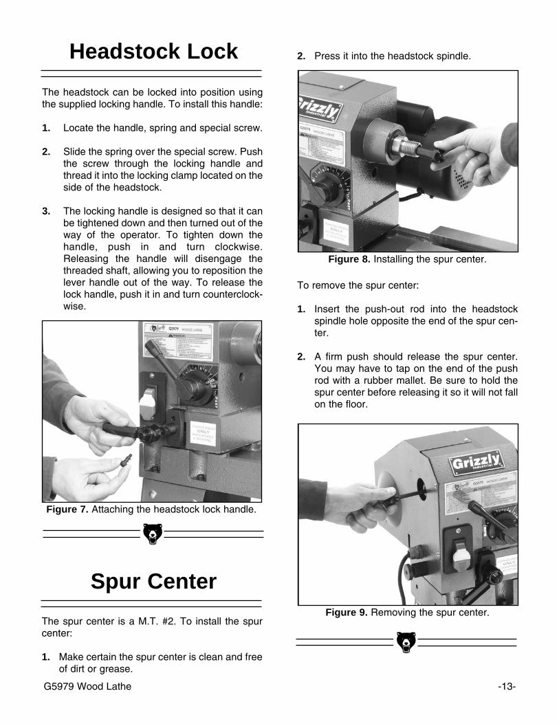
2. Press it into the headstock spindle.
To remove the spur center:
1. Insert the push-out rod into the headstockspindle hole opposite the end of the spur cen-ter.
2. A firm push should release the spur center.You may have to tap on the end of the pushrod with a rubber mallet. Be sure to hold thespur center before releasing it so it will not fallon the floor.
The spur center is a M.T. #2. To install the spurcenter:
1. Make certain the spur center is clean and freeof dirt or grease.
Spur Center
Figure 8. Installing the spur center.
Figure 9. Removing the spur center.

-14- G5979 Wood Lathe
The faceplate is used when turning plates, bowlsand vases. The headstock spur must be removedbefore installing the faceplate. To install the face-plate:
1. Remove the headstock spur using the pushrod.
2. Using two wrenches, thread on and tightenthe faceplate/workpiece assembly onto thethreaded spindle. Be sure to secure the face-plate tightly with two wrenches.
Faceplate
Figure 10. Attaching the faceplate.
The extension bed mounts to the left hand side ofthe main lathe bed. To attach the extension bed:
1. Align the mounting holes of the extensionbed and the main lathe bed.
2. Using the M10-1.5 x 25 cap screws and M10lock washers, attach the extension bed.
3. Be sure to securely tighten the cap screws.The extension bed does not have to be per-fectly level.
Extension Bed
Figure 11. Attaching extension table.

G5979 Wood Lathe -15-
SECTION 5: ADJUSTMENTS
Disconnect power to themachine when perform-ing any maintenance,assembly or adjust-ments. Failure to do thismay result in seriouspersonal injury.
!
Wear safety glassesduring the entire adjust-ment process. Failure tocomply may result inserious personal injury.
Keep loose clothingrolled up and out of theway of machinery andkeep hair pulled back.
The headstock has 5 preset positions: 0° for gen-eral spindle turning; 60°, 90° and 120° when doingfaceplate turnings where the workpiece extendsbelow the level of the lathe/extension bed; and180° when doing faceplate turning where theworkpiece edge does not extend below the edgeof the lathe/extension bed. To set the headstockto the desired degree:
1. Loosen the lock handle by turning counter-clockwise one full revolution.
2. Pull out on the headstock release knob androtate the headstock clockwise to the desiredsetting. The headstock will be fixed into posi-tion when it clicks into one of the 5 presetpositions.
3. Tighten the lock handle that was loosened inthe first step. Do not attempt to lock theheadstock into a position other than the 5presets.
Headstock
Figure 12. Adjusting headstock.
The tailstock can be moved along the length ofthe lathe bed. The tailstock barrel holds the livecenter, which can be adjusted up to 21⁄2" from thetailstock housing. To adjust the tailstock and tail-stock spindle:
1. Loosen the tailstock lock handle by loweringit and slide the tailstock to the desired posi-tion along the lathe bed. Retighten the tail-stock lock handle by lifting it. The lock handlemechanism can be adjusted by tightening orloosening the large hex nut under the tail-stock.
2. To adjust the tailstock barrel, loosen the spin-dle lock handle.
3. Rotate the tailstock spindle handwheel untilthe desired position is achieved. Retightenthe tailstock spindle lock handle.
4. To remove the live center from the tailstockspindle, use the push-out rod insertedthrough the hollow center of the tailstockspindle.
Tailstock
-16- G5979 Wood Lathe
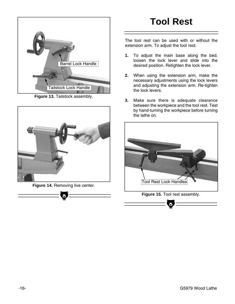
Figure 13. Tailstock assembly.
Figure 14. Removing live center.
Tool Rest
Figure 15. Tool rest assembly.
The tool rest can be used with or without theextension arm. To adjust the tool rest:
1. To adjust the main base along the bed,loosen the lock lever and slide into thedesired position. Retighten the lock lever.
2. When using the extension arm, make thenecessary adjustments using the lock leversand adjusting the extension arm. Re-tightenthe lock levers.
3. Make sure there is adequate clearancebetween the workpiece and the tool rest. Testby hand-turning the workpiece before turningthe lathe on.
Barrel Lock Handle
Tailstock Lock Handle
Tool Rest Lock Handles
G5979 Wood Lathe -17-
SECTION 5: OPERATIONS
Once assembly is complete and adjustments aredone to your satisfaction, you are ready to test runthe machine.
Press the START button. Make sure that your fin-ger is poised on the STOP button, just in casethere is a problem. The lathe should run smooth-ly, with little or no vibration or rubbing noises.Strange or unnatural noises should be investigat-ed and corrected before operating the machinefurther.
If you cannot easily locate the source of anunusual noise or vibration, contact our servicedepartment for help.
Test Run
Wear a face shield dur-ing the test run andoperation of this woodworking lathe. Failure todo so could result inserious injury.
Keep loose clothingrolled up and out of theway of machinery andkeep hair pulled back.
Speed Selector
The variable speed selector allows the adjust-ment of the spindle R.P.M. The lathe should onlybe turned ON when the speed is set at the lowestR.P.M. The lathe must be ON to adjust the speed;therefore, be sure to set the speed to the lowestR.P.M. before turning OFF the machine.
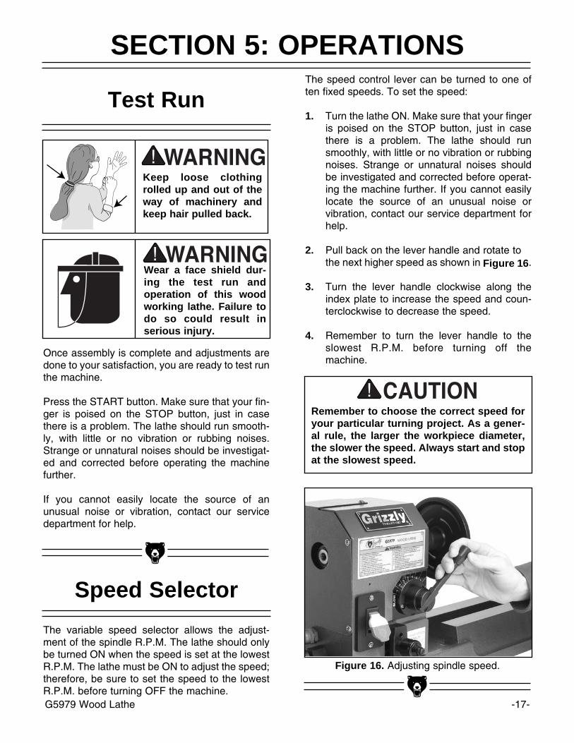
Figure 16. Adjusting spindle speed.
Remember to choose the correct speed foryour particular turning project. As a gener-al rule, the larger the workpiece diameter,the slower the speed. Always start and stopat the slowest speed.
The speed control lever can be turned to one often fixed speeds. To set the speed:
1. Turn the lathe ON. Make sure that your fingeris poised on the STOP button, just in casethere is a problem. The lathe should runsmoothly, with little or no vibration or rubbingnoises. Strange or unnatural noises shouldbe investigated and corrected before operat-ing the machine further. If you cannot easilylocate the source of an unusual noise orvibration, contact our service department forhelp.
2. Pull back on the lever handle and rotate to the next higher speed as shown in Figure 16.
3. Turn the lever handle clockwise along theindex plate to increase the speed and coun-terclockwise to decrease the speed.
4. Remember to turn the lever handle to theslowest R.P.M. before turning off themachine.

-18- G5979 Wood Lathe
To mount a workpiece between centers:
1. Locate the center point on both ends of theworkpiece by carefully drawing diagonal linesfrom corner to corner. The point of intersec-tion is the center of the work. Find the centerof a round workpiece by using a center finderinstrument.
2. When turning stock with a diameter greaterthan 2", remove the corner length edgesshown in Figure 17.
3. Line up the center of the spur center with thecenter mark on the end of the workpiece.While supporting the workpiece, slide the tail-stock close to the end of the workpiece andlock it into place.
4. Line up the live center with the center markon the other end of the workpiece. Turn thehandwheel to press the point of the live cen-ter into the workpiece.
5. Lock the tailstock in place.
Spindle Turning
D"
If measurement D" is greater than 2", cut off the corners of
the wood stock.
Wood Stock
Figure 17. Cross-section of turning stock.
Do not press too firmly or the bearings willbind and overheat. Likewise, do not adjusttoo loosely or the workpiece will spin offthe lathe. Use good judgement. Seriouspersonal injury could result if care is nottaken.

G5979 Wood Lathe -19-
1. Locate the center point of the workpiece bycarefully drawing diagonal lines from cornerto corner. The point of intersection is the cen-ter of the work. Find the center of round work-piece by using a center finder instrument.
2. Using 4 wood screws, attach the workpieceas close to the center of the faceplate as pos-sible. Make sure that the wood screws willnot interfere with the lathe chisels or intend-ed cuts.
3. Adjust the headstock to the desired positionfor the turning operation that you will be per-forming.
4. Attach the faceplate/workpiece assembly tothe headstock spindle using two wrenches.
Faceplate turning projects fall into two categories:those that extend below the level of thelathe/extension bed and those that do not. If yourproject will rotate below the level of thelathe/extension bed, you will need to rotate theheadstock to the 60° or 90° positions (discussedfurther in Adjustments section). But if your pro-ject does not extend below the lathe/extensionbed, it is safest to rotate the headstock 180° sothe project will rotate over the extension bed. Thisallows the operator to stand directly in front of theproject and allows use of the tool rest without theextension arm, thus, eliminating undue flexing ofthe tool rest.
Faceplate Turning
Figure 19. Faceplate turning large projects.
Adjust the tool rest as close to the workpiece aspossible without actually coming into contact withthe workpiece. Test by hand-turning the work-piece before turning the lathe on. Ensure that thelathe chisel is fully supported by the tool rest.Support the lathe chisel on the tool rest with onehand, while the other hand controls the chisel.See Figure 21.
Tool Rest
Figure 21. Proper hand positioning.
Wear a face shield dur-ing the test run andoperation of this woodworking lathe. Failure todo so could result inserious injury.
Figure 20. Faceplate turning small projects.

-20- G5979 Wood Lathe
SECTION 7: MAINTENANCE
Lubrication
V-Belt
All bearings are shielded and permanently lubri-cated. Simply leave them alone until they need tobe replaced. Do not lubricate them.
The end of the motor shaft has a lube fitting thatrequires periodic lubrication. It is very importantnot to over lube this fitting; otherwise, dirt anddebris will collect on the motor shaft, causing pre-mature failure of the pulley mechanism. We rec-ommend using a few shots of light spindle oil.
Inspect regularly for tension and wear. Check pul-leys to ensure that they are properly aligned. Seepulley/V-belt sections for proper tension and pul-ley alignment procedures.
Regular periodic maintenance on your ModelG5979 will ensure its optimum performance.Make a habit of inspecting your machine eachtime you use it. Check for the following conditionsand repair or replace when necessary:
1. Loose mounting bolts.
2. Worn switch.
3. Worn or damaged cords and plugs.
4. Damaged V-belt.
5. Any other condition that could hamper thesafe operation of this machine.
General
Dust/Chip Removal Saw dust and wood chips allowed to sit on castiron surfaces can trap moisture and cause rust.Regularly wipe or blow sawdust and chip buildupof of the lathe unit. This will help reduce thechance of rust.
RustThe nonpainted surfaces on the Model G5979should be protected against rust and pitting.Wiping the machine clean after every use ensuresthat wood dust will not trap moisture against baremetal surfaces.
Disconnect power to themachine when perform-ing any maintenance,assembly or adjust-ments. Failure to do thismay result in seriouspersonal injury.
!
Wear safety glassesduring the entire mainte-nance process. Failureto comply may result inserious personal injury.
Keep loose clothingrolled up and out of theway of machinery andkeep hair pulled back.

G5979 Wood Lathe -21-
The following pages contain general machinedata, parts diagrams/lists, a troubleshooting guideand Warranty/Return information for your ModelG5979.
If you need parts or help in assembling yourmachine, or if you need operational information,we encourage you to call our Service Department.Our trained service technicians will be glad to helpyou.
If you have comments dealing specifically withthis manual, please write to our Bellingham,Washington location using the address in Section3: Introduction.
We have included some important safety mea-sures that are essential to this machine’s opera-tion. While most safety measures are generallyuniversal, Grizzly reminds you that each work-shop is different and safety rules should be con-sidered as they apply to your specific situation.
We recommend you keep a copy of our currentcatalog for complete information regardingGrizzly's warranty and return policy. If you needadditional technical information relating to thismachine, or if you need general assistance orreplacement parts, please contact the ServiceDepartment listed in Section 3: Introduction.
Additional information sources are necessary torealize the full potential of this machine. Tradejournals, woodworking magazines, and your locallibrary are good places to start.
SECTION 8: CLOSURE
The Model G5979 was specifically designedfor wood turning operations. DO NOT MOD-IFY AND/OR USE THIS MACHINE FOR ANYOTHER PURPOSE. Modifications orimproper use of this tool will void the war-ranty. If you are confused about any aspectof this machine, DO NOT use it until all yourquestions have been answered or seriouspersonal injury may occur.
Like all power tools, there is danger asso-ciated with the Model G5979. Accidentsare frequently caused by lack of familiarityor failure to pay attention. Use this toolwith respect and caution to lessen thepossibility of operator injury. If normalsafety precautions are overlooked orignored, serious personal injury mayoccur.
Operating this equipment creates the poten-tial for flying debris to cause eye injury.Always wear safety glasses or goggleswhen operating equipment. Everyday glass-es or reading glasses only have impactresistant lenses, they are not safety glasses.Be certain the safety glasses you wear meetthe appropriate standards of the AmericanNational Standards Institute (ANSI).

-22- G5979 Wood Lathe
Customer Service #: (570) 546-9663 • To Order Call: (800) 523-4777 • Fax #: (800) 438-5901
MACHINE DATASHEET
Design Type ....................................................................................................Bench Model
Overall Dimensions:Height ......................................................................................................................44''Length ......................................................................................................................60''Shipping Weight ...............................................................................................190 lbs.Box Size ..................................................................................541⁄2" L x 13" W x 14" HFootprint ..................................................................................................431⁄2" x 181⁄2"
Construction:Bed ................................................................................................Cast Iron Flat WaysHeadstock........................................................................................................Cast Iron
Specifications:Inboard Spindle Size, Type ........................................................................1'' x 8 T.P.I.Tailstock ..............................................................................................................MT #2Spindle ................................................................................................................MT #2Range Of Speeds . . . . . . . . . . . . . . . . . . . . . . . . . . . . . . . . . . . . . . . . . . . . . . . . . . . . . . . . . . . . . . . . . . . . . . . . . . .10 @ 580 - 2850 R.P.M.Swing ........................................................................................................................12''Distance Between Centers ....................................................................................351⁄2''Swing Over Tool Rest . . . . . . . . . . . . . . . . . . . . . . . . . . . . . . . . . . . . . . . . . . . . . . . . . . . . . . . . . . . . . . . . . . . . . . . . . . . . . . . . . . . . . . . . . . . . . . . . . . . . . . . . . 9''Swivel Head ..............................................................................Stops @ 90° and 180°
Motor:Type ............................................................................TEFC Capacitor Start InductionHorsepower ........................................................................................................1⁄2 H.P.Phase ⁄ Cycle ..........................................................................................Single ⁄ 60 HzVoltage ..................................................................................................................110VAmperage..................................................................................................................4AR.P.M. ....................................................................................................................1720Bearings ..............................................................Sealed and Permanently Lubricated
Accessories:......................................................................................................................Tool Rest
........................................................................................................Live Rolling Center..................................................................................................................Spur Center....................................................................................................................Face Plate..........................................................................Extension Bed for Out-Board Turning......................................................................................................Tool Rest Extension................................................................................................................Paddle Switch
Specifications, while deemed accurate, are not guaranteed.
GRIZZLY MODEL G5979 SWIVEL HEAD WOOD LATHE

16
15
1210
97A59
8
30
5253
53-1
6857
A69
17A
58
11
44A
43
35
22
21-1
21
66
37
39
38
6A
5
4
36
25
41
41
40
55
44A43
24A
24-1
24-2
24-3
3
2
46
45
4749
48-1
50
4248
63
34
1
33
32
31
28
26
27
23
19
18
65-1
64
13
37
37
51
71
20
Lube
Fitt
ing
54-3
54-1
54-5
54-4
54-6
54-6
54-16061 62
6162
56
60
616162

G5979 Wood Lathe -25-
Ref# Part# Description
01 P5979001 HEADSTOCK
02 P5979002 DRIVE CENTER
03 P5979003 DISC
04 P5979004 SPINDLE
05 PK18M KEY 4 X 4 X 82
06A P5979006A BALL BEARING 80205Z
07A P5979007A BALL BEARING 80205Z
008 P5979008 SPRING
09 P5979009 BRACKET—SHIFTING LEVER
10 P6006 BALL BEARING 6006ZZ
11 P5979011 C-RING S-25
12 P5979012 SPINDLE PULLEY SET R & L
13 PVM23 V-BELT M-23 3L230
15 P5979015 C-RING S-24
16 P5979016 PIN-INJECTION
17A PLN09 LOCK NUT M12-1.75
18 P5979018 CLAMP LEFT
19 PB07M HEX BOLT M8-1.25 X 25
20 P5979020 RACK
21 P5979021 GEAR ASSEMBLY
21-1 PS09M PHLP HD SCR M5-.8 X 10
22 P5979022 CLAMP RIGHT
23 P5979023 SPECIAL SCREW
24A P5979024A SHAFT
24-1 P5979024-1 SPRING
24-2 P5979024-2 LOCK HANDLE
24-3 P5979024-3 SPECIAL CAP SCREW
25 P5979025 WRENCH
26 P5979026 C-RING S-16
27 P5979027 SLEEVE
28 P5979028 SPRING
30 P5979030 MOTOR PULLEY SET, L & R
31 PS09M PHLP HD SCR M5-.8 X 10
32 PK18M KEY 4 x 4 x 82
33 P5979033 1⁄2 H.P. MOTOR
34 P5979034 MOTOR COVER
35 P5979035 ANGULAR SETTING ASSEMBLY
36 P5979036 TOOL REST
37 P5979037 HANDLE ASSEMBLY
38 P5979038 EXTENSION TOOL REST
Ref# Part# Description
39 P5979039 TOOL REST BODY
40 P5979040 ECCENTRIC ROD
41 PR08M EXT RETAINING RING 19MM
42 P5979042 SPECIAL SCREW
43 P5979043 CLAMP
44A P5979044A HEX NUT M18-2.5
45 P5979045 CENTER
46 P5979046 TAIL SPINDLE
47 P5979047 TAILSTOCK SCREW
48 P5979048 TAILSTOCK
48-1 PPSS25M SET SCREW M6-1 X 20
49 P5979049 HANDWHEEL
50 P5979050 LOCK HANDLE-TAILSTOCK
51 P5979051 SPECIAL BOLT
52 P5979052 EXTENSION BED
53 PSB64M CAP SCREW M10-1.5 X 25
53-1 PLW06M LOCK WASHER 10MM
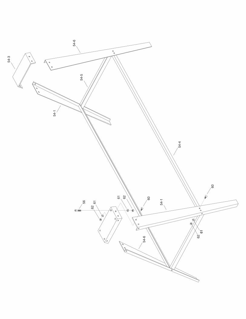
54-1 P5979054-1 STAND LEG, LEFT
54-3 P5979054-3 STAND UPPER COVER
54-4 P5979054-4 STAND LONG-CROSS SUPPORT
54-5 P5979054-5 STAND SHORT-CROSS SUPPORT
54-6 P5979054-6 STAND LEG, RIGHT
55 P5979055 BED
56 PSB11M CAP SCREW M8-1.25 x 16
57A PSW08 SWITCH 110V WITH KEY
58 PS21M PHLP HD SCR M4-.7 X 15
59 P5979059 PLASTIC JAM NUT M20 X 1.5
60 PCB02M CARRIAGE BOLT M8-1.25 x 10
61 PW01M FLAT WASHER 8MM
62 PN03M HEX NUT M8-1.25
63 PWRCRD110L POWER CORD 110V, LONG W/PLUG
64 P5979064 LOGO LABEL
65-1 P5979065-1 GRIZZLY ID/WARNING LABEL
66 P5979066 SPEED LABEL
68 P5979068 SWITCH BOX
69 P5979069 SWITCH FIXING PLATE
71 P5979071 MOTOR POWER WIRE

-26- G5979 Wood Lathe
Grizzly Industrial, Inc. warrants every product it sells for a period of 1 year to the original purchaser fromthe date of purchase. This warranty does not apply to defects due directly or indirectly to misuse, abuse,negligence, accidents, repairs or alterations or lack of maintenance. This is Grizzly’s sole written warrantyand any and all warranties that may be implied by law, including any merchantability or fitness, for any par-ticular purpose, are hereby limited to the duration of this written warranty. We do not warrant or representthat the merchandise complies with the provisions of any law or acts unless the manufacturer so warrants.In no event shall Grizzly’s liability under this warranty exceed the purchase price paid for the product andany legal actions brought against Grizzly shall be tried in the State of Washington, County of Whatcom.
We shall in no event be liable for death, injuries to persons or property or for incidental, contingent, spe-cial, or consequential damages arising from the use of our products.
To take advantage of this warranty, contact us by mail or phone and give us all the details. We will thenissue you a “Return Number,” which must be clearly posted on the outside as well as the inside of the car-ton. We will not accept any item back without this number. Proof of purchase must accompany the mer-chandise.
The manufacturers reserve the right to change specifications at any time because they constantly strive toachieve better quality equipment. We make every effort to ensure that our products meet high quality anddurability standards and we hope you never need to use this warranty.
Please feel free to write or call us if you have any questions about the machine or the manual.
Thank you again for your business and continued support. We hope to serve you again soon.
WARRANTY AND RETURNS

G5979 Wood Lathe -27-
10. Which benchtop tools do you own? Check all that apply.
___1" x 42" Belt Sander ___6" - 8" Grinder___5" - 8" Drill Press ___Mini Lathe___8" Table Saw ___10" - 12" Thickness Planer ___8" - 10" Bandsaw ___Scroll Saw___Disc/Belt Sander ___Spindle/Belt Sander___Mini Jointer
___Other__________________________________________________
11. How many of the machines checked above are Grizzly? ____________
12. Which portable/hand held power tools do you own? Check all that apply.
___Belt Sander ___Orbital Sander___Biscuit Joiner ___Palm Sander___Circular Saw ___Portable Planer___Detail Sander ___Saber Saw___Drill/Driver ___Reciprocating Saw___Miter Saw ___Router
___Other__________________________________________________
13. What machines/supplies would you like Grizzly Industrial to carry?
__________________________________________________________
__________________________________________________________
14. What new accessories would you like Grizzly Industrial to carry?
__________________________________________________________
__________________________________________________________
15. What other companies do you purchase your tools and supplies from?
__________________________________________________________
__________________________________________________________
16. Do you think your purchase represents good value?
___Yes ___No
17. Would you recommend Grizzly Industrial to a friend?
___Yes ___No
18. Would you allow us to use your name as a reference for Grizzly customersin your area? Note: We never use names more than three times.
___Yes ___No
19. Comments:_________________________________________________
__________________________________________________________
__________________________________________________________
__________________________________________________________
__________________________________________________________
1. How did you learn about us?
___Advertisement ___Friend___Catalog ___Card Deck___World Wide Web
___Other__________________________________________________
2. Which of the following magazines do you subscribe to.
___American Woodworker ___Practical Homeowner___Cabinetmaker ___Shop Notes___Family Handyman ___Today’s Homeowner___Fine Homebuilding ___WOOD___Fine Woodworking ___Wooden Boat___Home Handyman ___Woodshop News___Journal of Light Construction ___Woodsmith___Old House Journal ___Woodwork___Popular Mechanics ___Woodworker___Popular Science ___Woodworker’s Journal___Popular Woodworking ___Workbench
___Other__________________________________________________
3. Which of the following woodworking/remodeling shows do you watch?
___Backyard America ___The New Yankee Workshop___Home Time ___This Old House___The American Woodworker ___Woodwright’s Shop
___Other__________________________________________________
4. What is your annual household income?
___$20,000-$29,999 ___$60,000-$69,999___$30,000-$39,999 ___$70,000-$79,999___$40,000-$49,999 ___$80,000-$89,999___$50,000-$59,999 ___$90,000 +
5. What is your age group?
___20-29 ___50-59___30-39 ___60-69___40-49 ___70 +
6. How long have you been a woodworker?
___0 - 2 Years ___8 - 20 Years___2 - 8 Years ___20+ Years
7. How would you rank your woodworking skills?
___Simple ___Advanced___Intermediate ___Master Craftsman
8. What stationary woodworking tools do you own? Check all that apply.
___Air Compressor ___Panel Saw___Band Saw ___Planer___Drill Press ___Power Feeder___Drum Sander ___Radial Arm Saw___Dust Collector ___Shaper___Horizontal Boring Machine ___Spindle Sander___Jointer ___Table Saw___Lathe ___Vacuum Veneer Press___Mortiser ___Wide Belt Sander
___Other__________________________________________________
9. How many of your woodworking machines are Grizzly? _____________
Name ____________________________________________________________________________________Street ____________________________________________________________________________________City ______________________________________________________________State________Zip_________Phone Number_______________________E-Mail_______________________FAX________________________MODEL # G5979 Wood Lathe Order #______________________________________________
The following information is given on a voluntary basis. It will be used for marketing purposes to help us develop better products and services. Of
course, all information is strictly confidential.
WARRANTY CARD

FOLD ALONG DOTTED LINE
FOLD ALONG DOTTED LINE
GRIZZLY INDUSTRIAL, INC.P.O. BOX 2069BELLINGHAM, WA 98227-2069
PlaceStampHere
TAPE ALONG EDGES--PLEASE DO NOT STAPLE
Name_______________________________
Street_______________________________
City______________State______Zip______
Send a Grizzly Catalog to a friend:

