122622365-manual-dp210
TRANSCRIPT

WORKSHOP MANUALDP210 FUEL INJECTION PUMP DDNX184(EN)
2003

(D) Schutzbrille/Gesichtsschutz tragen.
(E) Úsese protección para los ojos/la cara.
(EN) Wear eye/face protection.
(F) Porter un appareil de protection des yeux / du visage.
(IT) Proteggersi gli occhi/la faccia.
(NL) Veiligheidsbril/-masker gebruiken.
(P) Use protecção da face/olhos.
(D) Von Zündquellen fernhalten - Nicht rauchen.
(E) Conservar alejado de toda llama o fuente de chispas -No fumar.
(EN) Keep away from sources of ignition - No smoking.
(F) Conserver à l'écart de toute flamme ou source d'étincelles - Ne pas fumer.
(IT) Conservare lontano da fiamme e scintille - Non fumare.
(NL) Ver van open vuur en ontstekingsbronnen houden – Niet roken.
(P) Mantenha afastado de fontes de ignição – Proibido fumar.
(D) Geeignete Schutzhandschuhe tragen.
(E) Usen guantes adecuados.
(EN) Wear suitable gloves.
(F) Porter des gants appropriés.
(IT) Usare guanti adatti.
(NL) Aangepaste veiligheidshandschoenen dragen.
(P) Use luvas apropriadas.
(D) Kommen Sie nicht mit dem Hochdruckstrahl in Verbindung! Besonders nicht, wennDruckrohrleitung oder Dichtung geprüft werden! Hochdruckflüssigkeiten können tödli-che Verletzungen verursachen! Im Falle einer Berührung mit der Haut, kontaktieren Siesofort einen Arzt. Bitte beachten Sie die Gesundheits-/und Sicherheitsunterlagen.
(E) Mantenga las manos y el cuerpo lejos del rociado del líquido, especialmente inyecto-res, tuberías y juntas de alta presión con fugas. La inyección de alta presión puede per-forar la piel humana y producir una lesión fatal. En caso de que la inyección atraviesela piel, consiga atención médica inmediatamente. Vea la hoja de Datos de Sanidad ySeguridad.
(EN) Do not put your skin into the fuel jets under pressure, especially those due to pressurepipe or seal leaks. High pressure liquids can cause deadly injuries. In case of an injec-tion under the skin, contact a doctor immediately. Please refer to the health and secu-rity fuel documents.
(F) Ne pas approcher les mains ni le corps des jets de liquides, particulièrement ceux pro-venant des fuites de tuyaux et des joint soumis a la haute pression. Le liquide soushaute pression injecté sous la peau peut causer des blessures mortelles. En cas d’in-jection sous la peau, consulter immédiatement un médecin. Se reporter a la fiche desanté et de sécurité du gazole.
(IT) Non esporre le mani o altre parti del corpo a getti di gasolio ad alta pressione, spe-cialmente a quelli provenienti da tubi o paraolii. I getti di liquidi ad alta pressione pos-sono causare ferite anche mortali. In caso di iniezione sotto pelle contattare immedia-tamente un medico. Fare riferimento alle schede di sicurezza del gasolio.
(NL) Zorg dat uw handen of andere lichaamsdelen niet in contact komen met vloeistofstra-len onder hoge druk, met name bij een lek aan een leiding of dichting. Als de vloeistofonder hoge druk onder de huid terechtkomt, kan dit zelfs tot dodelijke verwondingenleiden. Als de vloeistof onder de huid terechtkomt, onmiddellijk een arts raadplegen.Lees de gezondheids- en veiligheidsfiche met betrekking tot de brandstof.
(P) Não exponha a pele a jactos de combustível sob pressão, especialmente os devidos afugas de tubos de pressão ou vedantes. Líquidos a alta pressão podem causar ferimen-tos mortais. No caso de injecção subcutânea, consulte imediatamente um médico.Consulte por favor a documentação respeitante a saúde e segurança de combustíveis.

CONTENTS
© Delphi Diesel Systems UK Ltd
Publication N°: DDNX184(EN) 2K/03.03/FOLIUM i
INTRODUCTION 1
DISMANTLING 2
COMPONENT INSPECTION AND RENEWAL 3
REASSEMBLY 4
TEST PROCEDURE 5
TOOLING, TORQUES & EVDS 6

BC - Boost Control
CA - Cold Advance
CP - Zero Backlash Drive
CPS - Carriage Position Sensor
DCU - Diesel Control Unit
ESOS - Electric Shut-Off Solenoid
EVD - Exploded View Diagram
FIE - Fuel injection Equipment
HP - High Pressure
LLA - Light Load Advance
OEM - Original Equipment Manufacturer
SIN - Service Instruction Note
TP - Transfer Pressure
NOTATIONAL CONVENTIONS AND ABBREVIATIONS
ii
Produced by:
Delphi Diesel Aftermarket Operations
Stratford Road
Shirley, Solihull Tel.: (44) (0)121 746 6000
B90 4DT, UK Fax: (44) (0)121 746 6001

1 INTRODUCTION
1.1 The Pump .........................................................................................................................................................................7
1.2 General ........................................................................................................................................................................7 - 8
1.3 This Manual......................................................................................................................................................................8
1.4 Equipment ........................................................................................................................................................................8
1.5 Replacement of Parts.......................................................................................................................................................8
1.6 Pump Name Plate.......................................................................................................................................................8 - 9
2 DISMANTLING
2.1 Preparation .....................................................................................................................................................................11
2.1.1 Cleaning and draining........................................................................................................................................11
2.1.2 Mounting the pump ...........................................................................................................................................11
2.1.3 Sealing caps and drive shaft lock bolt..............................................................................................................11
2.1.4 Drive hub (if fitted) .............................................................................................................................................12
2.1.5 Measuring drive shaft end float ........................................................................................................................12
2.1.6 Measuring drive shaft radial play .....................................................................................................................12
2.2 Drive Shaft......................................................................................................................................................................13
2.3 High Pressure Outlets and End Plate Assembly .........................................................................................................13
2.3.1 High pressure outlets ........................................................................................................................................13
2.3.2 Endplate assembly .....................................................................................................................................13 - 14
2.4 Electric Shut-off Solenoid (ESOS) ................................................................................................................................14
2.5 Transfer Pump................................................................................................................................................................14
2.6 Governor Cover External Components .......................................................................................................................15
2.6.1 Fuel return connections ....................................................................................................................................15
2.6.2 Throttle lever stop screws, maximum fuel adjuster blanking plug and torque control screw ..................15
2.6.3 Throttle lever ......................................................................................................................................................16
2.7 Governor Cover .............................................................................................................................................................16
2.7.1 Governor cover with torque control only ................................................................................................16 - 17
2.7.2 Governor cover fitted with boost control ................................................................................................17 - 19
2.8 All Speed Governor ......................................................................................................................................................19
2.9 Governor Control Bracket and Arm Assembly ..........................................................................................................19
2.9.1 Scroll link plate return spring ...................................................................................................................19 - 20
2.9.2 Governor control bracket assembly ................................................................................................................20
2.9.3 Governor control arm assembly ......................................................................................................................20
2.10 Slackening the Transfer Pump Rotor ..........................................................................................................................20
2.11 Advance Device .....................................................................................................................................................20 - 21
2.11.1 Cam screw...........................................................................................................................................................22
2.12. Head Locating Fittings and Hydraulic Head ................................................................................................................22
2.12.1 Head locking screws...........................................................................................................................................22
2.12.2 Light load advance (LLA) ...................................................................................................................................22
2.12.3 Latch valve ..........................................................................................................................................................22
2.12.4 Releasing the hydraulic head ............................................................................................................................23
2.12.5 Drive assembly ...........................................................................................................................................23 - 24
2.13 Drive Shaft Seal(s) ........................................................................................................................................................24
3 COMPONENT INSPECTION AND RENEWAL
3.1 Cleaning..........................................................................................................................................................................25
3.2 General............................................................................................................................................................................25
3.2.1 Mated and matched assemblies .......................................................................................................................25
3.2.2 Examination and replacement ..........................................................................................................................25
CONTENTS
iii

3.2.3 Seals ....................................................................................................................................................................25
3.3 Details .............................................................................................................................................................................25
3.3.1 Hydraulic head rotor ..........................................................................................................................................25
3.3.2 Hydraulic head plungers....................................................................................................................................25
3.3.3 Cam ring and scroll plates.................................................................................................................................25
3.3.4 Rollers and shoes ...............................................................................................................................................25
3.3.5 Transfer pump .............................................................................................................................................25 - 26
3.3.6 Endplate...............................................................................................................................................................26
3.3.7 Control valves .....................................................................................................................................................26
3.3.8 Delivery valves and cambox pressurising valves ...........................................................................................26
3.3.9 Springs ................................................................................................................................................................26
3.3.10 Fittings and threads............................................................................................................................................26
3.3.11 Linkages...............................................................................................................................................................26
3.3.12 Throttle shaft.......................................................................................................................................................26
3.3.13 Drive shafts and associated components ........................................................................................................26
3.3.14 Advance device...................................................................................................................................................26
3.3.15 External controls.................................................................................................................................................26
3.3.16 Pump housing.....................................................................................................................................................26
3.3.17 Governor control cover......................................................................................................................................26
3.3.18 Orifices.................................................................................................................................................................26
3.3.19 Electric shut-off solenoid ...................................................................................................................................26
3.4 Storage ..........................................................................................................................................................................26
3.4.1 New pumps ........................................................................................................................................................26
3.4.2 Overhaul pumps ................................................................................................................................................26
3.4.3 Storage conditions ............................................................................................................................................27
4 REASSEMBLY
4.1 Preparation .....................................................................................................................................................................29
4.1.1 Hydraulic head....................................................................................................................................................29
4.2 Drive Shaft......................................................................................................................................................................29
4.2.1 Catch and support plates...................................................................................................................................29
4.2.2 Rollers and shoes ...............................................................................................................................................29
4.2.3 Governor weight cage ......................................................................................................................................30
4.2.4 Fitting the governor weight assembly to the drive shaft ..............................................................................30
4.2.5 O-ring and rear scroll plate ..............................................................................................................................30
4.2.6 Cam ring, front scroll plate and inner bearing ........................................................................................30 - 31
4.2.7 Drive shaft assembly .........................................................................................................................................31
4.2.8 Fitting the pump housing .................................................................................................................................31
4.3 Drive Shaft Seals, End Float and Radial Play .............................................................................................................31
4.3.1 Drive shaft seals ................................................................................................................................................32
4.3.2 Securing the drive shaft ....................................................................................................................................32
4.3.3 Measuring drive shaft end float ........................................................................................................................32
4.3.4 Measuring drive shaft radial play .....................................................................................................................33
4.4 Hydraulic Head, Cam Screw and Head Locating Fittings ..........................................................................................33
4.4.1 Aligning the hydraulic head ..............................................................................................................................33
4.4.2 Cam advance screw ...........................................................................................................................................33
4.4.3 Head locating fittings .........................................................................................................................................34
4.5 Advance Device ......................................................................................................................................................34 - 35
CONTENTS
iv
CONTENTS
v
4.5.1 Fitting the advance device assembly to the pump housing...........................................................................35
4.5.2 Tightening the head fittings and advance end plates .....................................................................................36
4.6 Governor Control Bracket and Arm Assembly..................................................................................................................36
4.6.1 Governor control arm assembly .............................................................................................................................36
4.6.2 Fitting the governor control bracket assembly......................................................................................................37
4.6.3 Scroll link plate return spring ..................................................................................................................................37
4.6.4 Setting the governor link length..............................................................................................................................37
4.7 Governor Cover ..............................................................................................................................................................38
4.7.1 Governor covers fitted with boost control .....................................................................................................38 - 39
4.7.2 Governor cover fitted with torque control only.....................................................................................................39
4.7.3 Assembling the torque trimmer ......................................................................................................................39 - 40
4.7.4 Throttle shaft and governor main spring ..............................................................................................................40
4.7.5 Fitting the governor cover .......................................................................................................................................40
4.8 Governor Cover External Components ..............................................................................................................................41
4.8.1 Throttle levers............................................................................................................................................................41
4.8.2 Throttle lever stop screws, maximum fuel screw and torque control screw.............................................41 - 42
4.8.3 Fuel return connections............................................................................................................................................42
4.9 Drive Hub, Transfer Pump and Endplate Assembly ........................................................................................................42
4.9.1 Drive hub ...................................................................................................................................................................42
4.9.2 Transfer pump rotor .................................................................................................................................................42
4.9.3 Internal recirculation (if fitted) ................................................................................................................................43
4.9.4 Assembling the transfer pump ...............................................................................................................................43
4.9.5 Endplate assembly ...........................................................................................................................................43 - 44
4.10 ESOS and High Pressure Outlets ........................................................................................................................................44
4.10.1 ESOS ..................................................................................................................................................................44 - 45
4.10.2 High pressure outlets and clamp plate ..................................................................................................................45
4.11 Drive Shaft Lock Bolt, Drain Plug and Cam Advance Screw...........................................................................................45
4.11.1 Drive shaft lock bolt .................................................................................................................................................45
4.11.2 Drain plug ..................................................................................................................................................................46
4.11.3 Cam advance reading screw ...................................................................................................................................46
4.12 Leak Testing ...........................................................................................................................................................................46
5 TEST PROCEDURE
5.1 Pump Specification........................................................................................................................................................47
5.1.1 Rotation ...............................................................................................................................................................47
5.1.2 Gov. link length...................................................................................................................................................47
5.1.3 Plunger diameter ................................................................................................................................................47
5.1.4 Drive type ............................................................................................................................................................47
5.1.5 Pump features.....................................................................................................................................................47
5.1.6 OEM code............................................................................................................................................................47
5.2 Test Conditions...............................................................................................................................................................48
5.2.1 Test fluid ..............................................................................................................................................................48
5.2.2 Inlet feed pressure..............................................................................................................................................48
5.2.3 Nozzles.................................................................................................................................................................48
5.2.4 Nozzle opening pressure ...................................................................................................................................48
5.2.5 Nozzle holder ......................................................................................................................................................48
5.2.6 H.P. pipes .............................................................................................................................................................48
5.3 Pre-Test Notes ................................................................................................................................................................49
5.3.1 Introduction.........................................................................................................................................................49
5.3.2 Leak testing .........................................................................................................................................................49

CONTENTS
vi
5.3.3 Test machine drive .............................................................................................................................................49
5.3.4 Pre set notes ................................................................................................................................................49 - 50
5.4 Test Procedure................................................................................................................................................................50
5.4.1 Introduction.........................................................................................................................................................50
5.4.2 Warm-up and stabilisation.................................................................................................................................50
5.4.3 Initial settings .....................................................................................................................................................51
5.4.4 Transfer pressure ........................................................................................................................................51 - 52
5.4.5 Cambox pressure ...............................................................................................................................................52
5.4.6 Speed advance ............................................................................................................................................53 - 54
5.4.7 Cold advance ..............................................................................................................................................54 - 55
5.4.8 Light load advance......................................................................................................................................55 - 56
5.4.9 Maximum fuel.....................................................................................................................................................56
5.4.10 Torque trimmer ...........................................................................................................................................57 - 58
5.4.11 Boost control.......................................................................................................................................................59
5.4.12 Latch Valve ..........................................................................................................................................................60
5.4.13 Maximum fuel adjustment ................................................................................................................................61
5.4.14 Torque screw ...............................................................................................................................................61 - 62
5.4.15 Governor ......................................................................................................................................................62 - 63
5.4.16 Light Load Valve .................................................................................................................................................63
5.4.17 Idle setting...........................................................................................................................................................64
5.4.18 ESOS....................................................................................................................................................................65
5.4.19 Timing..................................................................................................................................................................65
5.5 Overcheck Procedure ....................................................................................................................................................66
5.5.1 Introduction.........................................................................................................................................................66
5.5.2 Pump preparation...............................................................................................................................................66
5.5.3 Test machine drive .............................................................................................................................................66
5.5.4 Overcheck pre-set notes .............................................................................................................................66 - 67
5.5.5 Overcheck test procedure ..................................................................................................................................67
6 TOOLING, TORQUES & EVD’s
6.1 Tooling..........................................................................................................................................................69 - 70
6.2 Torque values......................................................................................................................................................71
6.3 EVD ..............................................................................................................................................................72 - 76

INTRODUCTION
1 - 7
1.1 THE PUMP
The DP210 distributor-type fuel injection pump is a
compact, self-contained unit that is suitable for
direct injection engines of up to 33 BHP per cylinder
and with three, four or six cylinders with either
clockwise or anticlockwise gear drives. It is primarily
intended for diesel engines which have to meet the
Tier 2 off-highway exhaust emissions legislation for
the industrial and agricultural markets in Europe
and USA.
All internal working parts are lubricated by fuel oil
and the pump housing is maintained at an internal
pressure that prevents the ingress of external dirt or
other foreign matter.
Standard features include improved shaft locked
orientation timing, servo controlled light load
advance and speed advance with solenoid switched
cold advance, torque trimmer control of maximum
fuel delivery including excess fuel for starting,
transfer pressure curve slope adjustment with
viscosity compensation.
It can also be fitted with a range of options to suit
particular customer and engine rating
requirements, including boost-pressure control for
turbocharged engines, high strength camrings,
quick fit low pressure connections and throttle
levers with combined break-back and throttle return
spring features.
Due to the complexity of this product, the need for
highly trained personnel, and a high level of
investment in equipment and workshop resources,
together with the need for up-to-date Technical
Information, it can only be tested or serviced by a
Delphi authorised distributor.
It has been developed from the well-known range of
DPA, DPS and DP200 injection pumps and is the
result of the Delphi policy of continued
improvement of products to meet the demands of
new legislation and operational requirements.
1.2 GENERAL
Fuel pumps may require off-engine workshop
attention for two main reasons:
(a) Investigation of a specific fault in engine
performance, which may only require partial
dismantling.
(b) A complete overhaul e.g. at the same time as a
major engine overhaul.
3433

INTRODUCTION
1 - 8
A full performance test is recommended, both
before and after any level of attention, as many
aspects of pump performance are interrelated.
1.3 THIS MANUAL
The Dismantling, Reassembly and Testing Sections
are laid out on a “step-by-step” basis, with each
action accompanied by an illustration showing the
component(s) involved and where applicable,
its/their positions on the pump. The Manual is not
based on any one specification, but covers pump
features which have been included up to the time of
publication. For the purposes of illustration, more
than one pump specification has been used.
The pumps illustrated are for clockwise rotation
(when viewed from the drive end). Any component
used for anticlockwise pumps that is different, is
individually described.
1.4 EQUIPMENT
Any tools, both standard and special-purpose, usedfor the servicing or repair of fuel injection equipment(FIE) must be reserved solely for use on FIE. Worn ordamaged tools can cause damage to criticalcomponents, as well as being a safety hazard.
The working area must be scrupulously clean andshould be in a room separated from any otheractivity; the ingress of dust and dirt, airborne orotherwise, must be prevented.
The minimum facilities required are:
1. A bench covered in non-rusting metal or industrial-grade linoleum and fitted with an engineer’s vicewith a jaw size of 100 mm (4 in). The vice jaws mustbe faced with either soft metal or fibre pads.
2. An adjustable pump-mounting device such as the“Hydraclamp”, fitted with an appropriate adaptorplate.
3. Easily cleaned compartmented trays for separatestorage of dismantled pumps are available fromDelphi Aftermarket Operations, Service OperationsDepartment.
4. All the necessary tools are listed in Section 6 of thismanual.
5. A low-pressure washing facility using a suitable,approved, cleaning fluid (not water or water-based)to clean pumps externally prior to dismantling.Cleaning must be carried out in a place separatedfrom the “clean area”.
6. A tank large enough to accommodate a completepump and filled with clean test oil, near to a sourceof clean, dry, variable pressure compressed air forcarrying out leakage tests.
7. Supplies of clean, lint-free (non-fluffy) cloths forcleaning and drying components. Cotton waste mustnever be used.
8. A pump test machine that conforms to ISO 4008.
9. Adequate storage facilities for pumps, tools and testequipment, with separate areas for pumps beforeand after repair.
Note: All cleaning tanks, workshop and test facilitiesand fluids must conform to any Fire Prevention orHealth and Safety Regulations in force at the time ofuse.
1.5 REPLACEMENT OF PARTS
All gaskets and seals must be replaced during
reassembly. However, in the event of partial
dismantling, only those seals that have been
disturbed need replacement, unless leaks from
elsewhere are detected during testing prior to
dismantling.
If any part of a “mated” assembly is worn or
damaged, the whole assembly must be replaced.
Any component showing signs of corrosion or water
ingress, cracks or distortion must be replaced.
Only service parts supplied by Delphi Aftermarket
Operations may be used as replacements. Parts
supplied from alternative sources may appear to be
externally similar and may carry the same part
numbers as the genuine item but may be inferior in
material specification or finish and lead to
malfunction or premature failure.
1.6 PUMP NAME PLATE
The number stamped on the type-plate attached to
the pump housing identifies the type and model of
the pump. Pumps with identical build but with
different settings, dependent upon engine
application, are further identified by the setting code
stamped beneath the serial number.
A typical Despatch Number could be as shown in Fig.
1.
Note 1: The pumps shown in the illustrations do notnecessarily represent any one specification, butare used to show particular features.
Note 2: As components are removed, inspect them andput those considered unfit for further service toone side for replacement; place those whichare fit for further service into a cleancompartmented tray. (Trays available throughDelphi Diesel Systems Aftermarket Operations,Service Operations Department.) A guide toareas of possible wear or damage appears inSection 3 (Component Inspection & Renewal).

INTRODUCTION
1 - 9
C 93 2 0 A 00 0 L
If the name plate has been painted over, special care is needed when removing the paint to avoid erasure of theinformation. Use a small quantity of proprietary paint-stripper, carefully observing the manufacturer’s instructions.
Marketing Code:
C = Spain
No letter = UK
Product Type (DP210)
Suffix letter -
Denotes the type of
ESOS fitted.
See SIN DT294
Change to the individual
specification affecting parts
interchangeability, but not fit or
function of pump.
Individual features
number.
Design change letter -
Has no significance at the
time of publication of this
manual
No. of delivery outlets:
0, 3 & 5 = 4 cyl.
1 & 4 = 6 cyl.
2 = 3 cyl.
6 - 9 to be allocated
Design Source:
0 = USA 1 = Korea
2 & 3 = UK
4 = France
5 = Spain 6 = Brazil
7 = India 8 = Poland
9 = Japan
Fig. 1 Explanation of Despatch Number

INTRODUCTION
1 - 10

DISMANTLING
2 - 11
2.1 PREPRATION
A list of all tools required to dismantle the pump is
given in Section 6.
2.1.1 Cleaning and draining
Externally clean the pump. Remove the drain plug
(1) and drain any fuel oil remaining in the housing.
If the pump is suspected to be faulty, or is subject to
a warranty assessment, a preliminary test on the test
machine may be required. In this case, externally
clean the pump as above but drain the fuel oil into a
clean container for possible subsequent analysis.
If the pump has not seized and it is to be tested prior
to dismantling, examination will first be necessary to
determine if dirt or water ingress has occurred, so as
to avoid contamination of the test fuel and possible
damage to the test equipment.
If it is not possible to see through the drain plug
hole, remove the spring end cover plate of the
advance device (see Section 2.11) and closely
examine the components for signs of corrosion or
metal particles.
Note: Do NOT remove the advance device as removalof the HLF will destroy the knife edge sealing ofthe plug.
If there is no contamination, refit the end cover plate,
using a new O-ring. Tighten the two screws to the
respective torque and proceed with the test.
2.1.2 Mounting the pump
Mount the pump on a Hydraclamp using a mounting
plate (1) with a suitable adaptor ring.
Align the pump with its axis horizontal and the
governor cover uppermost.
2.1.3 Sealing caps and drive shaft lock bolt
Remove any shrink sleeving or tamperproof caps
from adjustment screws. Remove the drive shaft
lock screw and washer (1) and discard the O-ring.
Remove the plug that enables accsess to the cam
ring for the advance readings (not shown).
3433
3449
3450
1
1
1

DISMANTLING
2 - 12
2.1.4 Drive hub (if fitted)
Restrain the drive hub with the special tool. Slacken
the drive hub nut and spring washer just sufficiently
to allow release of the hub.
Use a suitable extractor to release the hub from the
drive shaft taper. Remove the woodruff key (if fitted).
2.1.5 Measuring drive shaft end float
Note: To assess the condition of components subjectedto end-thrust, end-float must be measured priorto dismantling. The pump and gauge must beclamped to an assembly plate mounted in a viceor on a Hydraclamp.
Fit the appropriate adaptor (3) to the drive shaft
thread. Screw in the dial gauge holder (1), and fit the
gauge (2). Adjust the gauge pin to contact the thrust
washer (4). Push the drive shaft inwards and set the
dial gauge to zero. Pull the drive shaft outwards and
note the maximum gauge reading, ensuring the
thrust washer (4) remains against the pump housing.
End-float should be 0.05mm to 0.2mm. If the
maximum is exceeded, examine the housing thrust-
faces during dismantling. If no significant wear or
damage is apparent, requiring replacement of the
pump housing, correct the end-float by the use of
alternative shims during reassembly.
2.1.6 Measuring drive shaft radial play
Note: In order to assess the condition of the bearing anddrive shaft, radial play must be measured prior todismantling.
With the pump and gauge (1) mounted rigidly
relative to each other, adjust the gauge pin to bear (at
right angles) against the parallel section (2) of the
drive shaft.
Note that this section is very short, therefore a fine tipwill be required on the gauge pin. Push the shaftradially towards the gauge and set the gauge tozero.
Pull the shaft radially to the opposite extreme and
record the gauge movement. Repeat the readings
with the gauge repositioned as shown at (3) and (4).
Do not rotate the drive shaft. Reject the housing if the
maximum play is 0.27mm or the difference between
the measurements exceeds 0.2mm.
1863
A1005
2
4
1
3
12 3
4

DISMANTLING
2 - 13
2.2 DRIVE SHAFT
Remove the circlip (2) and thrust washer (1).
2.3 HIGH PRESSURE OUTLETS AND ENDPLATE ASSEMBLY
2.3.1 High pressure outlets
Turn the pump vertical so that the endplate is
uppermost.
Remove all the nuts (1) securing the clamping plate
(2) to the outlet connections, and remove the plate.
If fitted, remove the four support plate screws and
the pump-to-engine support bracket (not shown).
The outlets contain delivery valves that must be
retained in their matched seat / valve pairs.
Unscrew and remove each high pressure outlet (1),
using a long-reach socket, and then remove the
delivery valves (2), delivery valve springs and pegs.
Delivery valve holders must be discarded.
Remove and discard the seating washer from the
bottom of each outlet bore.
2.3.2 Endplate assembly
2.3.2.1 Removing the endplate assembly
Slacken, but do not remove, the fuel inlet
connection (1). Slacken and remove the four
endplate screws (2) and remove the endplate
assembly (3) complete.
1865
4000
4001
4002
1
2
1
2
12
2
1
2
3
22

2138
DISMANTLING
2 - 14
2.3.2.2 Internal components
Remove the fuel inlet connection (1) and discard
the O-ring (2). Tip out the filter (3) together with
the end plate sleeve assembly and remove the
piston retainer (12), the piston (10) and the
regulating springs with spring peg (8). From the
opposite end of the regulating sleeve unscrew
the double adjuster (4) using a 4.5mm hex key.
Remove the O-ring (5) and discard. With a 2mm
hex key remove, clockwise, the inner adjuster
(6), remove the O-ring (7) and discard. From the
regulating sleeve remove and discard the O-ring
(11).
Note: The piston, sleeve and adjusters arematched and are not interchangeable.
Remove the sandwich plate (13).
Note: If damaged carefully remove thesandwich plate locating pin (14) from the endplate using a pair of long nose pliers. Note theparticular hole in the endplate to which it isfitted. Incorrect fitting when reassembling willaffect transfer pump operation.
2.4 ELECTRIC SHUT-OFF SOLENOID (ESOS)
Remove any detachable electrical connections, nut
and washer, depending upon the type of ESOS
fitted; slacken and remove the ESOS body. Remove
and discard the O-ring.
2.5 TRANSFER PUMP
Note: Make a note of the orientation of the transfer pumpliner (2) before dismantling, particularly the positionof the recess (1) in one face, to aid correctreassembly.
Remove the transfer pump sealing ring (3).
Carefully lift out the liner together with the two pairs
of transfer pump blades (4) and their separating
springs (5).
CAUTION: The springs are very small and could be easilymislaid.
Note: Care must be taken to avoid damage to the bladefaces during storage or assembly.
If internal recirculation is fitted, remove the spring
and poppet valve assembly (1) which is retained
within the barrel by the liner.
1889
3
2
45
1
E2322
1
2
3
4
5
6
7
8
9
10
11
12
1314
E2322
E251
1

DISMANTLING
2 - 15
2.6 GOVERNOR COVER EXTERNALCOMPONENTS
2.6.1 Fuel return connections
Note: Fuel return arrangements will vary, dependentupon the pump specification.
Align the pump with its axis horizontal and the
governor cover uppermost.
Unscrew the tube nut (1), the banjo bolt (2) and
remove the drain pipe (3). Discard the two sealing
washers from the banjo bolt.
If any backleak connections are fitted unscrew and
remove them. Discard any washers.
2.6.2 Throttle lever stop screws, maximum fueladjuster blanking plug and torque control screw
Loosen the lock nuts on the idling stop screw (1),
and torque screw (3), and remove the screws and
washers. Using a pair of “molegrips” grip and undo
the conical tamperproof nut of the maximum speed
screw (2). Remove and discard the nut and screw.
Discard any rubber sealing washers.
Using the special tool, slacken and remove the
blanking plug (1) on the side of the governor cover.
Discard any sealing washer.
3456
3456
1901
2165
1
3
1 2
1
2
3

DISMANTLING
2 - 16
2.6.3 Throttle lever
2.6.3.1 Rigid type
Remove and discard the self-locking nut (1);
remove washer (2), upper spring retainer (3),
spring (4), spring retainer (6), spacer (5), throttle
lever (7), and dust cap (8).
2.6.3.2 Break-back type
Remove and discard the self-locking nut (11);
remove washer (10), upper spring retainer (9),
spring (8), spacer (7), lower spring retainer (6)
and washer (1). Remove break-back lever (2) and
throttle lever (4) together with spring (3). Remove
dust cover (5).
2.7 GOVERNOR COVER
2.7.1 Governor cover with Torque Control only
Remove the pressure end plug circlip (1).
2.7.1.1 Spring end components
Note: It may be necessary to re-position thepump on the Hydraclamp mounting plate to gainaccess to the preload plug.
Unscrew and remove the plug (1) and discard the
O-ring.
E2631
1907
1916
1
1
1
2
3
4
5
6
7
8
4912
11
10
9
8
7
6
1
2
4
5
3

DISMANTLING
2 - 17
Remove the large spring (4), the spring plate (5)
(if fitted), and the small spring (6) (if fitted).
Remove shim(s) (2) from inside preload plug (1);
remove and discard the O-ring (3).
2.7.1.2 The pivot plug
If no boost control is fitted, the cam follower will
be pivoted on a spindle, which is formed as part
of a pivot plug (1) screwed into the governor
control cover. If the pivot plug is to be removed,
slacken it by no more than one turn before
removal of the governor control cover (to avoid
the risk of damage to internal components).
2.7.2 Governor cover fitted with Boost Control
Note the position of the air inlet connection (3) on
the boost control cover.
2.7.2.1 Boost control cover and diaphragm
Slacken and remove the cover fixing screws (2).
Caution: The cover (1) will be lifted up under theaction of the diaphragm return spring as thescrews are loosened.
Remove the cover and the diaphragm assembly
(1).
If fitted, remove the shim from within the “cup”
in the lower face of the diaphragm assembly.
Note 1: Do not dismantle the diaphragmassembly as this is a factory-assembled item. Ifany part of it is worn or damaged, the wholeassembly must be replaced.
E2711
2123
1922
1
2
1
3
E2712
1 2 3 4 5 6
1
2

DISMANTLING
2 - 18
Note 2: The spring, spring seat and spindle (3),cannot be lifted out at this stage, as they areretained by the cam follower and a circlip withinthe governor cover.
Push the throttle shaft (2) down into the cover.
Remove the Torx screws (1) securing the
governor cover.
2.7.2.2 Removing the governor cover
Lift and rotate the cover off towards the torque
trimmer side, and push the throttle shaft (2) out
of its bore. Remove and discard the “trapped” O-
ring (1) from the sealing face of the cover.
Remove the O-ring from the transfer port and
discard.
Note: If the control cover is lifted too far, thecarriage angle plate may become distorted; ifresistance is felt, lower it and move it furtheraway, then lift it again.
2.7.2.3 Removing the piston and the pressure end plug
Tip out the torque trimmer cam (1); remove and
discard circlip (2) (if fitted). Tip out piston (3). Use
a suitable piece of soft metal or plastic rod to
push the plug (5) out of the cover; remove and
discard the O-ring (4).
2.7.2.4 Removing the cam follower and its pivot
Remove the small circlip (3) and the cam follower
(1) from the spindle (2). The washer behind the
cam follower (not visible) may be difficult to
extract and can be left until the spindle is
removed.
2122
E2723
1
2
1924
3
2
1
1
1
1
1 2 3 4 5
2115
1
2
3

DISMANTLING
2 - 19
If no boost control is fitted to the governor cover
remove the small circlip (4) and the cam follower
(3). Unscrew and remove the pivot plug (1); at
which point the washer (not visible) can be
removed from the spindle. Remove and discard
the O-ring (2).
2.7.2.5 Boost housing
Remove the spindle (1), spring seat washer (2),
spring (3) and shim (4). Remove the stroke
adjuster (6) from the body (7) and discard the O-
ring (5). Using the special tool slacken and
remove the stroke adjustment screw body (7),
the shim (8) and the housing (9). Remove the
dowel pin (10) if damaged. Remove and discard
O-ring (11).
2.8 ALL-SPEED GOVERNOR
Detach the governor main spring (5) from the idling
spring peg (3). Remove the peg, idling spring (2) and
pivot ball washer (1) from the governor arm (4).
Remove the main spring from the throttle shaft link
(6).
Remove and discard the O-rings from the throttle
shaft (7).
2.9 GOVERNOR CONTROL BRACKET AND ARMASSEMBLY
2.9.1 Scroll link plate return spring
Push the scroll link plate (3), to compress the spring
and expose the end of the spring pin (1); grip the end
of the pin, release the scroll link plate and pull the
pin away from the spring stop (2). Tip the
“shouldered” end of the pin upwards to clear the
spring stop and carefully release and remove the pin
and spring.
Warning
Cover the pin and spring with a non-fluffy
cloth in case it is released prematurely,
allowing it to be ejected at speed.
1937
2104
6
5
4
1
2 3
7
3
1
2
3
E2725
2115
A1473
1
2
4
3
1
2
3
6
5
4
7
8
9
10
11

DISMANTLING
2 - 20
2.9.2 Governor control bracket assembly
Straighten the “ears” of the two tab washers (3) and
(5). Slacken and remove the control plate screws (2)
and (6) and discard tab washers.
Note: Screws are of a different length and head shapeso a note must be made of their respectivepositions.
Lift out the bracket and anchor plate (7) together
with the control arm assembly (4) and the metering
valve (1), from the pump housing.
2.9.3 Governor control arm assembly
Unscrew and remove the linkage lock nut (7) and
adjusting nut (6). Remove the pivot ball washer (5).
Withdraw the linkage hook with the washer and
spring (3) from the governor control arm (4); remove
the spring retainer (2), and metering valve assembly
(1) from the linkage hook.
2.10 SLACKENING THE TRANSFER PUMPROTOR
Temporarily refit a drive hub and key to the shaft and
push the hub fully onto the shaft taper; hold the hub
with the special tool (2). Hold the transfer pump
rotor with the special tool (1). Slacken but do not
remove the TP rotor; the direction in which it is to be
slackened can be determined by examination of the
end face of the TP rotor.
TP rotors marked with an arrow indicate a clockwise
(left handed thread) direction in which to turn the
rotor to remove it.
Remove the tools; drive hub and key, leaving the TP
rotor just finger-tight.
2.11 ADVANCE DEVICE
Align the pump vertically with the transfer pump
uppermost.
Slacken but do not remove the cold start solenoid (1)
and the four end plate bolts (2) and (5).
Slacken and remove the cap nut (3). Slacken and
undo the head locating fitting (4) no more than two
turns.
Push the advance assembly back onto the pump
housing enabling the head locating fitting to be
released and it to be fully removed. Remove the O-
rings and discard, noting their relevant positions.
1949
1954
1
4
3
25
1
2
1943
1948
1 2 3 4 5 6 7
4
3
5
6
2
7
1

DISMANTLING
2 - 21
Remove the HLF plug (2) in the end by inserting a
suitable bar (1) in to the centre of the sleeve to allow
it to be gripped, without collapsing, with a pair of
side cutters to assist its removal. The sleeve will
collapse if no bar is inserted.
Note: DO NOT push the sleeve any further in to the headlocating fitting otherwise it will be unable to beremoved and a new head locating fitting will have tobe used.
Remove the advance device. Remove and discard
the advance housing gasket and the cap nut washer.
Remove the solenoid and discard the O-ring.
Remove the two screws and plate from the spring
end (1), opposite end to the cold start solenoid.
Remove the control spring and shim, remove and
discard the O-ring.
From the pressure end remove the two screws and
plate. Remove and discard the O-ring.
Slide out the advance piston and servo valve
assembly.
Remove the servo valve assembly from the advance
piston. Using suitable spanners grip and remove the
light load screw (1) from the light load piston (2).
Lightly grip in a rubber jawed vice whilst pushing
down on the light load piston (2), compress the
spring (3) sufficiently to expose the retaining E-clip
(1). Remove the E-clip from the servo shaft (6),
gently release the spring pressure, lift off the light
load piston with the spring and bottom spring plate
(4). Only remove the bottom E-clip (5) if damaged.
1961
1968
2
1
1971
1 2
1
E46
12
3
45
6

DISMANTLING
2 - 22
2.11.1 Cam screw
Using a suitable socket and wrench, slacken but do
not remove the cam screw.
If the cam ring has become stuck, remove the
wrench and socket from the cam advance screw and
tap the screw sideways with a soft-faced mallet until
the cam has been released. Remove the cam screw
from the cam ring.
2.12 HEAD LOCATING FITTINGS ANDHYDRAULIC HEAD
2.12.1 Head locking screws
Align the pump horizontally with the top of the
pump uppermost.
Note: Before removing the head locating fittings makea note of their relative positions.
Slacken and remove the two head locking screws (1)
and (2); remove and discard the O-rings and the
filters (if fitted) in the inner ends of the screws.
2.12.2 Light Load Advance (LLA)
Remove the tamper resistant plug (5) from the
valve body (2). Unscrew and remove the
adjusting screw and tapered valve pin (4) from
the body. Remove and discard the O-ring (3).
Note: It is advisable to retain the filter (1) within thebody of the valve and to clean and clear anyforeign matter with the use of dry compressedair. The process of removing the filter willdamage the valve body and will require a newLLA valve to be fitted.
2.12.3 Latch valve
Remove the tamper resistant plug (1). Unscrew
and remove the adjuster (3) from the body (6)
and tip out the spring (4) and piston (5). Remove
and discard the O-rings (7) and (8).
E2123
1972
1979
E2121
21
2
3
4
5
1
1 2 3 4 56
7 8

DISMANTLING
2 - 23
2.12.4 Releasing the hydraulic head
To release the hydraulic head twist and pull until the
large O-ring (1) is just exposed.
Align the pump with its axis vertical and with a
twisting action lift the head out of the pump housing;
carefully hold the plungers within the rotor and
invert the hydraulic head.
Note: The rear scroll plate may adhere to the face of thehydraulic head, if it does, remove it.
Place a plunger retaining cap (2) over the rotor;
remove and discard the large O-ring (1).
Keep the hydraulic head either in a bath of clean test
oil, ensuring that the exposed part of the rotor is
covered or in a clean plastic bag until it is required
for reassembly.
2.12.5 Drive assembly
2.12.5.1 Drive shaft
Twist and push the drive shaft carefully up
through the front bearing and remove it from the
pump, holding the rollers and shoes in position
as the shaft is lifted above the cam ring.
2.12.5.2 Rollers and shoes
Remove the rollers and shoes, keeping them in
their matched pairs.
1984
1995
1998
1
1
2
2002

DISMANTLING
2 - 24
2025
E21254
2005
2
3
2.12.5.3 Catch and support plates
If the roller cage is to be removed, place a
suitable “tommy” bar (1) through the transverse
hole in the drive shaft; support the drive shaft in
a vice fitted with soft jaws, without gripping it
and use the “tommy” bar to resist the slackening
torque.
Use a “Torx” screw bit and adaptor to remove
the four catch plate screws. Remove the catch
plate (2) and shoe plate (3).
2.12.5.4 Cam and scroll rings and bearing
Remove the rear scroll plate (7) (if still within the
housing), cam ring (6), front scroll plate (5), inner
bearing (4), and the governor weight cage
assembly complete with the weights, thrust
sleeve and thrust washer. Remove the weights
(8), thrust sleeve (3) and thrust washer (2) from
the weight cage (1).
2.13 DRIVE SHAFT SEAL(S)
Reposition the hydraclamp so that the drive shaft
seals are uppermost.
Using the special seal removal tool, carefully lever
out the seal noting the way round the seal is fitted
into the housing.
If two seals are fitted, remove the circlip spacer and
using the special seal removal tool, carefully lever
out the seal noting the way round the seal is fitted
into the housing.
1
23
1
4
56
7
8
COMPONENT INSPECTION AND RENEWAL
3 - 25
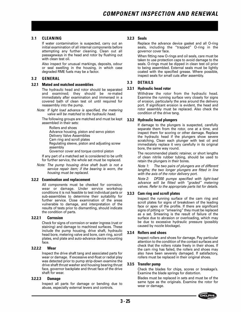
3.1 CLEANINGIf water contamination is suspected, carry out aninitial examination of all internal components beforeattempting any further cleaning. Clean out allpassageways in the head and rotor by flushing outwith clean test oil.
Also inspect for unusual markings, deposits, odouror seal swelling in the housing, in which casedegraded RME fuels may be a factor.
3.2 GENERAL
3.2.1 Mated and matched assembliesThe hydraulic head and rotor should be separatedand examined; they should be re-matedimmediately after examination and immersed in acovered bath of clean test oil until required forreassembly into the pump.
Note: If light load advance is specified, the meteringvalve will be matched to the hydraulic head.
The following groups are matched and must be keptassembled in their sets:
Rollers and shoesAdvance housing, piston and servo pistonDelivery Valve AssembliesCam ring and scroll platesRegulating sleeve, piston and adjusting screw assemblyGovernor cover and torque control piston
If any part of a matched set is considered to be unfitfor further service, the whole set must be replaced.
Note: The pump housing drive shaft bush is not aservice repair item; if the bearing is worn, thehousing must be replaced.
3.2.2 Examination and replacementAll components must be checked for corrosion,wear or damage. Under service workshopconditions it is not feasible to test individual parts orsub-assemblies to determine their suitability forfurther service. Close examination of the areasvulnerable to damage, and interpretation of theresults of tests prior to dismantling, should indicatethe condition of parts.
3.2.2.1 CorrosionCheck for signs of corrosion or water ingress (rust orstaining) and damage to machined surfaces. Theseinclude the pump housing, drive shaft, hydraulichead bore, metering valve and bore, cam ring, scrollplates, end plate and auto-advance device mountingface.
3.2.2.2 WearInspect the drive shaft tang and associated parts forwear or damage. If excessive end-float or radial playwas detected prior to pump strip-down examine thedrive shaft thrust washer and housing bearing thrustface, governor backplate and thrust face of the driveshaft for wear.
3.2.2.3 DamageInspect all parts for damage or bending due toabuse, especially external levers and controls.
3.2.3 SealsReplace the advance device gasket and all O-ringseals, including the “trapped” O-ring in thegovernor cover face.
When fitting new O-rings and oil seals, care must betaken to use protection caps to avoid damage to theseals. O-rings must be dipped in clean test oil priorto being assembled. External seals must be lightlycoated with the specified grease. Where possible,inspect seals for small cuts after assembly.
3.3 DETAILS
3.3.1 Hydraulic head rotorWithdraw the rotor from the hydraulic head.Examine the running surface very closely for signsof erosion, particularly the area around the deliveryport. If significant erosion is evident, the head androtor assembly must be replaced. Also check thecondition of the drive tang.
3.3.2 Hydraulic head plungersIf damage to the plungers is suspected, carefullyseparate them from the rotor, one at a time, andinspect them for scoring or other damage. Replacethe hydraulic head if the plungers show severescratching. Clean each plunger with test oil andimmediately replace it very carefully in its originalbore, the same way round.
The recommended plastic retainer, or short lengthsof clean nitrile rubber tubing, should be used toretain the plungers in their bores.
Note 1: The two pairs of plungers are of differentlengths; the two longer plungers are fitted in linewith the axis of the rotor delivery port.
Note 2: DP200 pumps specified with light-loadadvance will be fitted with “graded” meteringvalves. Refer to the appropriate parts list for details.
3.3.3 Cam ring and scroll platesInspect the running surface of the cam ring andscroll plates for signs of breakdown of the leadingface or apex of the profile. If there are significantsigns of pitting or “smearing” they must be replacedas a set. Smearing is the result of failure of thesurface due to abrasion or overloading, which maybe due to excessive hydraulic pressure (possiblycaused by nozzle blockage).
3.3.4 Rollers and shoesInspect rollers and shoes for damage. Pay particularattention to the condition of the contact surfaces andcheck that the rollers rotate freely in their shoes. Ifthe cam ring has failed, the rollers and shoes mayalso have been severely damaged. If satisfactory,rollers must be replaced in their original shoes.
3.3.5 Transfer pumpCheck the blades for chips, scores or breakage’s.Examine the blade springs for distortion.
Blades must be replaced in sets and must be of thesame type as the originals. Examine the rotor forwear or damage.

COMPONENT INSPECTION AND RENEWAL
3 - 26
Examine the liner for corrosion or scoring andreplace it if there are any signs of damage.
3.3.6 EndplateExamine the inner face of the end plate for wear.Replace it if there is any significant scoring. If thesandwich plate is scored or worn, it must bereplaced and not reversed.
3.3.7 Control valvesCheck all control valves for wear or scoring.Examine the metering valve for “stepping” of thecontrol slot edges and at the point where it entersthe bore in the hydraulic head. Check that the valveand the governor link pin are securely fixed in thebar and that the roller is free to rotate on the pin andis not worn. Check the regulating sleeve and pistonand differential valve for damage, corrosion orblockage of orifices.
3.3.8 Delivery valves and cambox pressurising valvesCheck for erosion or other damage to delivery valveassemblies. Replace them (as matched pairs) ifnecessary.
If movement of the cambox pressurising valve canbe detected when shaken, the spring may havecollapsed, in which case the whole assembly mustbe replaced, as it is a factory-sealed item.
3.3.9 SpringsLook for distorted or fractured springs. Very carefullyexamine the areas of contact with adjoiningcomponents (spring pegs, throttle shaft links etc).
Check that all springs specified in the Parts List forthe pump are present.
3.3.10 Fittings and threadsCheck all screws and nuts for damage.
Check all threads for damage, especially on thetransfer and distributor rotors, hydraulic head, camadvance screw hole, studs, fuel inlet and return andhigh pressure outlet connections.
3.3.11 LinkagesInspect all mechanical governor linkages, shafts,pivot pins and arms for wear, cracks or scoring oftheir mating surfaces.
3.3.12 Throttle shaftExamine the throttle shaft and its associated bore inthe governor cover for distortion, wear andlooseness of joints or elongation of spring anchorhole.
3.3.13 Drive shafts and associated componentsInspect the shaft for wear or damage, especiallywhere the oil seal contacts the shaft. Check the tangslot on CP drive pumps.
Examine the thrust surfaces on the inner face of thepump housing and the weight cage for damage orscoring.
Examine the governor weight cage and weights forwear, cracks or damage. Ensure that the correctnumber and type of governor weights are fitted.
3.3.14 Advance deviceExamine the components for corrosion. If water hasbeen present in the fuel it will tend to settle in theadvance housing. Check that the piston and servopiston moves freely.
3.3.15 External controlsExamine all levers for cracks and for excessive wearat contact points.
3.3.16 Pump housingExamine the housing for damage, especially tosealing surfaces. If the bearing is unfit for furtherservice, the housing must be replaced. If theadvance device stud is damaged replace thehousing.
3.3.17 Governor control coverCheck the control shaft bore, stop screw threads,and adjusting screw seal spotfaces. Check the boostcontrol locating dowel pin. Check the torquetrimmer piston bore.
3.3.18 OrificesExamine all orifices for blockage and carefully clearany obstruction with dry compressed air.
3.3.19 Electric shut-off solenoidEnsure that all the solenoid electrical parts are clean,especially the connection(s). Check that the flexiblevalve seat is in good condition, with no pitting orother damage. Check the coil for electrical continuityby measuring its resistance. Ensure that thesolenoid is completely dry and check insulationresistance between each terminal and the solenoidbody (insulated return solenoids only).
Note 1: A few solenoids are specified to beoperated only when there is a requirement to stopthe engine.
Note 2: If any fault is apparent in the stopsolenoid assembly, the whole unit must be replaced.
3.4 STORAGE
3.4.1 New pumps
New pumps must be stored in their “as received”
condition, with their original packaging intact.
3.4.2 Overhauled pumps
Run the pump at full load and half maximum speed
for 5 minutes on ISO 4113 test oil. Drain the oil; fit
the drain plug and tighten it to the specified torque.
Fit protection caps to the inlet and outlet
connections and seal the pump, together with some
rust-preventing material, in damp-proof packaging.

3.4.3 Storage conditions
Pumps must be stored in a dry, dust-free area, away
from direct sunlight or contact with any artificial
heat source.
The temperature limits of the storage area must be
between minus 30° C and plus 60° C. Humidity must
be between 0% and 80%.
Pumps must be stored with the axis horizontal;
unboxed pumps must not be stored one on top of
another.
A stock-rotation system must be observed to
minimise storage time of any individual pump. If a
pump has been stored for one year, it should be
subjected to a full test according to the relevant Test
Plan and the storage procedure repeated.
COMPONENT INSPECTION AND RENEWAL
3 - 27

COMPONENT INSPECTION AND RENEWAL
3 - 28
REASSEMBLY
4 - 29
4.1 PREPARATION
Before using thread-locking compound, if
specified, ensure that the mating surfaces are
completely oil-free and dry.
When reassembling pumps, it is important to use
the correct overhaul kits. The relevant kit numbers
can be found in the Service Parts List.
Lightly lubricate all flexible seals and O-rings with
clean test oil before fitment to their respective
components. Always use the correct protection cap
when fitting new O-rings. Apply the specified grease
to the drive shaft seal and the throttle shaft before
assembly in their respective positions. Dip all
internal components in clean test oil before
assembly.
Refer to the relevant Test Plan for details of special
build items and any initial setting instructions.
Refer to Section 6 for all special tools and torque
values.
The direction of rotation of the pump, as shown on
the nameplate, is as viewed from the drive end.
4.1.1 HYDRAULIC HEAD
The plungers in four-plunger rotors must be fitted
with the longer plungers opposite to each other and
in line with the distributor port in the rotor.
4.2 DRIVE SHAFT
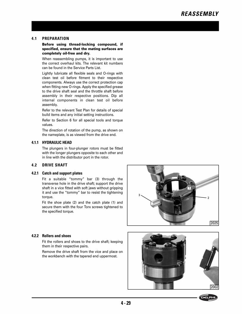
4.2.1 Catch and support plates
Fit a suitable “tommy” bar (3) through the
transverse hole in the drive shaft; support the drive
shaft in a vice fitted with soft jaws without gripping
it and use the “tommy” bar to resist the tightening
torque.
Fit the shoe plate (2) and the catch plate (1) and
secure them with the four Torx screws tightened to
the specified torque.
4.2.2 Rollers and shoes
Fit the rollers and shoes to the drive shaft; keeping
them in their respective pairs.
Remove the drive shaft from the vice and place on
the workbench with the tapered end uppermost.
2025
2002
3
1
2

REASSEMBLY
4 - 30
4.2.3 Governor weight cage
Fit the governor weights to the weight cage (1).
Arrange them so that, if there are less than six
weights (i.e. 4 or 3) they are symmetrically
positioned. If there are only three, place one in every
alternate “pocket”; if there are four, place them as
shown in the illustration.
Place the governor thrust washer (2) on (not under)
the “toes” (4) of the weights, followed by the thrust
sleeve (3).
4.2.4 Fitting the governor weight assembly to the driveshaft
Hold the weight cage and the governor thrust sleeve
assembly and invert it. Place the assembly over the
drive shaft and lower it, rotating it a little if necessary
to engage the splines on the drive shaft.
4.2.5 O-ring and rear scroll plate
Place the assembled hydraulic head on the
workbench with the pumping plungers uppermost,
ensuring they stay in position by use of the plunger
retaining cap (not shown). Align the cutaway part of
the drive tang (5) with the metering valve bore (3).
Fit a new O-ring into the groove (2) in the hydraulic
head.
Place one of the scroll plates (1) in the recess in the
hydraulic head (the “rear” scroll plate position).
Ensure that its arrow is facing in the correct direction
of rotation (as indicated on the pump nameplate)
and the slot (4) is centralised in the gap in the
hydraulic head, as shown.
4.2.6 Cam ring, front scroll plate and inner bearing
Place the cam ring (1) on the hydraulic head, with its
arrow facing in the direction of pump rotation, and
with the cam advance screw hole (2) aligned with
the head locating fitting hole (3).
2006
2007
2011
2014
A1503
12
3
4
3
2 1
4
1
2
5
3

REASSEMBLY
4 - 31
Place the front scroll plate on the cam with its arrow
pointing in the direction of rotation and with the slot
(8) aligned with the metering valve bore (6).
Place the inner bearing (4) over the front scroll plate,
with its shallow recess facing downwards and the
wide slot (7) centralised in line with the metering
valve bore.
Ensure that both scroll plate slots are aligned with
each other and with the metering valve bore.
Note: The small blind hole (5) accommodates theextended shank of one of the governor platesecuring screws to prevent rotation of the innerbearing.
4.2.7 Drive shaft assembly
Hold the drive shaft assembly together and place it
into the assembled components on the hydraulic
head, rotating the shaft as necessary to align the slot
with the hydraulic head rotor “tang” and the drive
shaft keyway (1) in line with the metering valve bore
(3).
Rotate the shaft so that a gap (2) between any two
adjacent weight “pockets” is aligned with the
metering valve bore (3) to ensure that the head of the
advance housing stud will pass between the two
opposite “pockets” when the pump housing is fitted.
4.2.8 Fitting the pump housing
Align the head locating fitting hole (1) in the pump
housing with the matching hole (2) in the hydraulic
head and lower the housing onto the inner
components until it just touches the hydraulic head
O-ring (3).
4.3 DRIVE SHAFT SEALS, END FLOAT ANDRADIAL PLAY
Fit the pump to the Hydraclamp and align
horizontally with the top of the pump uppermost.
Grip the hydraulic head and, using a twisting and
pushing action, slide the head fully into the pump
housing.
2016
2018
2022
2030
5
6
48
7
1
2
3
1
2
3

REASSEMBLY
4 - 32
4.3.1Drive shaft seals
Fit the protection sleeve (1) over the tapered end of
the drive shaft. The sleeve must cover the circlip
groove in the drive shaft. Failure to do so will cause
the lip of the seal to be cut and create a fuel oil leak.
Fit a new seal into the pump housing. Ensure that
the seal is the correct way round as noted during
dismantling. Use the special punch tool (2) and a
soft-headed mallet to drive the seal fully into the
recess in the pump housing.
If a second drive shaft seal is required fit the circlip,
if specified, into the groove in the pump housing
seal recess. The circlip must be positioned within the
groove so that the ears are either side of the telltale
hole in the pump housing.
Repeat the process for fitting the first seal.
4.3.2 Securing the drive shaft
Fit the thrust washer (2) over the drive shaft and fit
the circlip (1) correctly into the shaft groove (3).
4.3.3 Measuring drive shaft end floatNote: If this dimension was found to be correct when
measured prior to dismantling, and nocomponents which could affect end-float havebeen replaced, it should not be necessary torepeat this measurement.
Fit the appropriate adaptor (3) to the drive shaft
thread. Screw in the dial gauge holder (5), and fit the
dial gauge (4). Adjust the gauge pin to contact the
thrust washer (1).
Push the drive shaft inwards and set the dial gauge
to zero. Pull the drive shaft outwards and note the
maximum gauge reading ensuring the thrust
washer (1) remains against the pump housing. End-
float should be between 0,05mm and 0,2mm. If it is
outside that tolerance, correct it by the use of an
alternative thrust washer (1).
2033
2042
2044
2034
3
1
2
54
1
2
3
12

REASSEMBLY
4 - 33
4.3.4 Measuring drive shaft radial play
Note: If the original housing and shaft are to be usedand radial play at the bearing was found to bewithin the limits stated below, it should not benecessary to measure radial play at this stage. Ifeither item has been replaced, radial play mustbe measured.
With the pump and dial gauge (1) mounted rigidly
relative to each other (e.g. on a plate fitted to the
Hydraclamp), adjust the gauge pin to bear against
the parallel section (2) of the drive shaft. Push the
shaft radially towards the gauge and set the gauge
to zero. Pull the shaft radially to the opposite
extreme and record the gauge movement.
Repeat the readings with the gauge repositioned as
shown at (3) and (4). Do not rotate the drive shaft.
Reject the housing if the maximum play is 0.27mm
or the difference between the measurements
exceeds 0.2mm.
4.4 HYDRAULIC HEAD, CAM SCREW ANDHEAD LOCATING FITTINGS
4.4.1 Aligning the hydraulic head
Re-align the Hydraclamp so the pump is horizontal
with the top of the pump uppermost.
Grip the hydraulic head and, using a twisting action
ensure the holes in the housing (1) and the hydraulic
head are aligned with each other.
4.4.2 Cam advance screw
Align the Hydraclamp to place the pump with its axis
vertical. Fit the cam advance screw (1) to the cam
ring and using a suitable socket fitted to a torque
wrench tighten the screw to the specified torque.
Note: During this operation, the cam ring usuallybecomes “jammed” in the housing. Using arubber or hide mallet, lightly tap the cam screwaxially to free the cam ring.
A1259
120º
2058
1
23 4
1
1 2028
2029
4
8
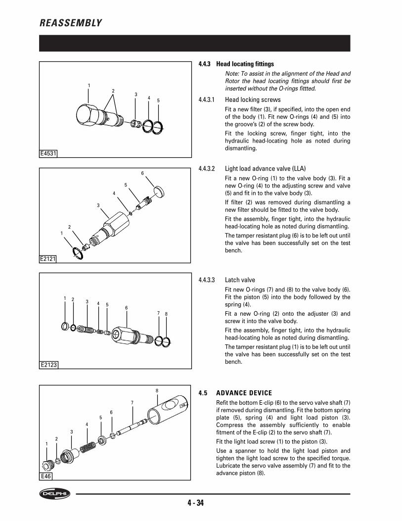
REASSEMBLY
4 - 34
4.4.3 Head locating fittings
Note: To assist in the alignment of the Head andRotor the head locating fittings should first beinserted without the O-rings fittted.
4.4.3.1 Head locking screws
Fit a new filter (3), if specified, into the open end
of the body (1). Fit new O-rings (4) and (5) into
the groove’s (2) of the screw body.
Fit the locking screw, finger tight, into the
hydraulic head-locating hole as noted during
dismantling.
4.4.3.2 Light load advance valve (LLA)
Fit a new O-ring (1) to the valve body (3). Fit a
new O-ring (4) to the adjusting screw and valve
(5) and fit in to the valve body (3).
If filter (2) was removed during dismantling a
new filter should be fitted to the valve body.
Fit the assembly, finger tight, into the hydraulic
head-locating hole as noted during dismantling.
The tamper resistant plug (6) is to be left out until
the valve has been successfully set on the test
bench.
4.4.3.3 Latch valve
Fit new O-rings (7) and (8) to the valve body (6).
Fit the piston (5) into the body followed by the
spring (4).
Fit a new O-ring (2) onto the adjuster (3) and
screw it into the valve body.
Fit the assembly, finger tight, into the hydraulic
head-locating hole as noted during dismantling.
The tamper resistant plug (1) is to be left out until
the valve has been successfully set on the test
bench.
4.5 ADVANCE DEVICE
Refit the bottom E-clip (6) to the servo valve shaft (7)
if removed during dismantling. Fit the bottom spring
plate (5), spring (4) and light load piston (3).
Compress the assembly sufficiently to enable
fitment of the E-clip (2) to the servo shaft (7).
Fit the light load screw (1) to the piston (3).
Use a spanner to hold the light load piston and
tighten the light load screw to the specified torque.
Lubricate the servo valve assembly (7) and fit to the
advance piston (8).
E4531
E46
1
34
E2123
E2121
3
4
5
6
2
1 2 3 4 56
7 8
12
3
4
56
7
8
2
5
1

REASSEMBLY
4 - 35
Lubricate and slide the advance piston assembly in
to the advance housing from the spring end (which
is the opposite end to the cold start solenoid)
ensuring that the port and slots (1) are inline with the
cold start solenoid hole (2).
Fit shim(s) (3), control spring (4) and a new O-ring
(5). Fit the end plate (6) and the two securing bolts (7)
finger tight.
Fit the plug (1) in to the head locating fitting (2) and
leave it protruding 4.1 ±0.2mm (A).
Note: Its final position will be set when the HLF istightened to the correct torque value.
4.5.1 Fitting the advance device assembly to the pumphousing
Fit new O-rings (2) and (3), as noted during
dismantling, to the grooves in the HLF (4).
Push the head locating fitting up through the larger
of the two holes in the advance housing. Place a new
gasket (1) onto the advance housing, with the
straight edge (7) adjacent to the pump housing stud
hole. Ensure that the shoulder of the head locating
fitting will not cut the gasket when the fitting is
tightened.
Place the advance housing over the stud and the
cam advance screw, and onto the pump housing,
ensuring that the gasket is correctly located over the
housing stud shoulder.
Note: The position of the piston may need to beadjusted to enable the cam advance screw to belocated.
Engage the fitting with the thread in the hydraulic
head and screw it fully in finger tight. If necessary
adjust the position of the hydraulic head.
Centralisation of the hydraulic head is necessary to
avoid damage to the O-rings as the head fixings are
screwed in.
Fit a new sealing washer (6) to the stud, followed by
2065
HLF
E461
12
E462
7 6 5 4 3
6
5
1
2
3
4
7
A1
2

REASSEMBLY
4 - 36
the cap nut (5).
4.5.2 Tightening the head fittings and advance endplates
Progressively tighten in the following order, LLA
valve, head locating fitting, head locking bolt or latch
valve to their specified torques.
Note: When all screws are tightened, check that theadvance piston moves freely within the advancehousing.
Warning: If the HLF is slackened once
tightened, the plug MUST be replaced.
On the pressure end fit the O-ring in to the advance
housing and then fit the end plate (3) and secure
with the two bolts (2). Tighten these and the spring
end bolts (4) to the correct torque.
Fit a new O-ring to the cold start solenoid (1) and fit
the solenoid to the advance housing and tighten to
the correct torque.
4.6 GOVERNOR CONTROL BRACKET AND ARMASSEMBLY
4.6.1 Governor control arm assembly
On to the linkage hook (9) place the spring retainer
(2), long spring (3), and washer (4). Feed the linkage
hook through the smaller of the two holes in the
upper part of the governor arm (5) and then fit the
pivot ball washer (6) with its dome towards the
governor arm, plain adjusting nut (7), and self-
locking nut (8). Leave the nuts at the outer end of the
thread. Their final position will be established when
the link-length is set.
Engage the hook of the link with the roller (1) of the
metering valve; with the open end of the linkage
hook facing the metering valve lift stop (10).
Assemble the control arm to the support bracket as
shown.
2066
1948
1 2 3 4 5 6 7 8
9
10
2
3
1
24
4

REASSEMBLY
4 - 37
4.6.2 Fitting the governor control bracket assembly
Align the pump horizontally with the top of the
pump uppermost.
Position the governor thrust sleeve so that the
“flats” are horizontal and visible through the access
hole (1). Ensure that the locating hole in the bearing
(5) is aligned with the governor control plate fixing
screw hole (2). Align the scroll plate slots (3) with the
metering valve bore (4).
Fit the assembled control arm and control bracket,
together with the metering valve, into the pump to
rest the control arm forks on the flats on the thrust
sleeve and the metering valve in to its bore. Fit the
arms of the scroll link plate into the scroll plate slots.
Fit a new tab washer, so that its lip will face
downwards, to the fixing screw with the longest
shank. Fit the screw at position (3), ensuring that it
enters the hole in the internal bearing.
Fit a new tab washer to screw (2), with its lip
positioned along the edge of the bracket.
Fit the plate (5 ) and hold in place with two screws
(1) and (4), as noted during dismantling. Check that
the scroll link plate is free, check that the governor
assembly is in the correct position, and then tighten
all control bracket screws to their specified torque
and bend up the locking tabs.
4.6.3 Scroll link plate return spring
Fit the spring over the spring pin (3) up to the pin
shoulder. Fully compress the spring; carefully grip
the pin and the spring and insert the exposed end of
the pin into the hole in the scroll link plate (4).
Transfer grip to the exposed end of the pin (1), push
the scroll link plate towards the pump centreline and
fit the spigot of the pin into the hole (2) in the spring
stop.
Caution: There is a risk of the spring and pin beingejected at high speed if grip is relaxed before thepin is securely fitted into the spring stop.
4.6.4 Setting the governor link-length
Set a vernier caliper (1) to the link-length specified in
the Test Pan. Move and hold the governor control
bracket to open the metering valve, i.e. towards the
head and rotor. Place one leg of the vernier gauge
against the smaller diameter of the metering valve
roller (3). Ensure that the gauge leg does not slip
into the link hook groove. With the use of a straight
edge guide against the end of the pump housing (2)
insert the other leg of the vernier gauge. Adjust and
lock the lock-nut on the end of the spring link to
obtain the test plan specified value.
SHOT1-2
2099
2104
4003
2095
1
43
2
3
5
2
4
1
5
3
2
4
1
3
1
2

REASSEMBLY
4 - 38
4.7 GOVERNOR COVER
4.7.1 Governor covers fitted with boost control
Note: The diaphragm assembly is a factory-assembleditem.
Fit a new O-ring (11) in the recess in the governor
control cover. Fit a new pin (10), if removed, into the
governor cover. Locate the boost control housing (9)
over the dowel pin (10) and secure it in position
using a new adjustment screw body (7) (and shim (8)
if fitted). Use the special tool to tighten the body to
the specified torque.
Fit a new O-ring (5) to the adjusting screw (6). Fit the
screw into the stroke adjustment screw body and
screw it into the body until the O-ring is just
concealed, or to a position specified in the relevant
Test Plan.
Place the shim (4) into the recess in the boost control
housing, followed by the spring (3). Fit the spring
plate (2) to the spindle (1) and place the spindle
assembly through the spring and the adjustment
screw (6).
Do not yet fit the cam follower to the spindle.
4.7.1.1 Setting the boost stroke
a) Fit the diaphragm assembly to the boost control
housing.
Fit a dummy cover (see tool list) to the housing
and secure it with the two screws.
Note: At this stage, the position of the boostpressure inlet is not important.
b) Fitting the gauge
Fit the special tool (1) and dial gauge (2) to the
cover, locking the gauge in position with the grub
screw (3). Set the gauge to zero then fully
depress the gauge pin (4) against the diaphragm
spring and note the reading. This “boost stroke”
will be specified in the test plan.
c) Adjusting the stroke
If adjustment is required, remove the cover and
dial gauge and the inner components. Rotate the
adjustment screw to increase or decrease the
stroke.
Note: Clockwise rotation of the strokeadjustment screw will increase stroke.
Replace the inner components, cover, gauge and
tool to check the stroke.
When the stroke has been set, remove the gauge
tool, temporary cover and diaphragm.
A796
4
2
1
3
E2725
1
2
3
6
5
4
7
8
9
10
11

REASSEMBLY
4 - 39
4.7.1.2 Fitting the cam follower
Place the washer (not shown) and the cam
follower (1) over the spindle (2) with the
“shaped” section of the follower facing into the
“window” (4) in the torque control bore. Fit a
new circlip (3) into the groove in the spindle.
4.7.1.3 Boost control cover and diaphragm
Invert the governor control cover again and
place it on the bench. If specified, fit the shim to
the “cup” in the lower face of the diaphragm
assembly (1) and fit the assembly to the boost
control housing.
Place the boost control cover (2) over the
diaphragm with the air inlet connection (4) facing
in the correct direction (as noted during
dismantling) and secure it in position with the
two screws (3), tightened to the specified torque.
4.7.2 Governor cover with torque control only
Fitting the pivot-plug.
If the cam follower and pivot-plug were removed
during dismantling, fit a new O-ring (2) to the pivot-
plug (1). Fit the pivot-plug to the governor control
cover and screw it in finger-tight. Fit washer (not
shown) to the pivot plug spindle (4) then the cam
follower (3) retained by a new circlip (5) as shown.
4.7.3 Assembling the torque trimmer
Fit circlip (8), if fitted, to the torque trimmer piston
(9). Fit the torque trimmer piston and circlip, with the
conical recess in the piston facing inwards (i.e.
towards the “spring” end), into the plain bore in the
governor control cover (13). Fit a new O-ring (10) to
the plain plug (11). Fit the plain plug and O-ring into
the governor control cover (13), pushing it far
enough to reveal the circlip groove. Fit a new circlip
(12) into the groove. From the opposite end of the
torque trimmer bore, use a suitable bar to push the
plug back against the circlip.
2115
2121
2115
E2723
2119
A1473
1
2
1
3
2
2
1
4
4
3
5
4
3
12
34
56
78
9
1011
12
A1473
13

REASSEMBLY
4 - 40
Fit the torque trimmer cam (7), with the small conical
end facing the piston. Fit the small spring (6) (if
specified) into the hollow end of the cam, followed
by the spring plate (5) and the large spring (4).
Fit a new O-ring (3) to the threaded pre-load plug (1).
Fit the shim (2) in to the preload plug and fit the plug
to the governor control cover and screw it in to the
position specified in the relevant Test Plan. If no
position is specified, leave the plug protruding from
the cover by approximately 4 mm. The final position
of the plug will be set during Testing.
4.7.4 Throttle shaft and governor main spring
Fit two new O-rings onto the throttle shaft (1).
Fit the idling spring (6) and the pivot ball washer (5)
(with its spherical face towards the governor arm) to
the spring guide (7). Fit the guide through the large
hole in the governor arm (4). Hook one end of the
governor main spring (3) through the hole in the end
of the guide and the other end through the hole in
the throttle shaft link (2).
4.7.5 Fitting the governor cover
Fit the pre-shaped trapped O-ring (2) to the governor
cover and a new O-ring in to the transfer port recess
(not shown). Fill the throttle shaft grease groove (3)
with the specified grease. Moisten the shaft with
clean test oil and push it up through the hole (1) in
the governor cover. Press the shaft firmly into place.
Place the cover assembly onto the pump, and use a
small hook tool through the maximum fuel adjusting
screw hole (1) in the cover to pull the carriage link
plate away from the torque trimmer cam. Once the
cover is lowered remove the hook tool and secure
the governor cover with the four Torx screws (2),
tightened to their specified torque.
2122
2123
1937
1
2
3 4
5
67
1 2
3
1
2
2
2
2
E2723
12
34
56
78
9
1011
12

REASSEMBLY
4 - 41
4.8 GOVERNOR COVER EXTERNALCOMPONENTS
4.8.1 Throttle levers
Rotate the throttle shaft fully anticlockwise
4.8.1.1 Rigid type
Fit the dust cap (8) to the throttle shaft boss. Fit
the lever (7), (ensuring that the flats in the hole of
the lever engage with the flats on the shaft), bush
(5), spring guide (6), and spring (4). Fit the spring
into the grooves in the spring guide and place
the lower (shorter) leg of the spring against the
maximum speed stop lug (9) and the upper
(longer) leg against the lever “upstand” (10). Fit
the upper spring retainer (3), small washer (2)
and self-locking nut (1), tightened to its specified
torque.
4.8.1.2. Break-back type
Fit the following components to the throttle
shaft; dust cap (5), throttle lever (4), break-back
lever (2). Fit spring (3) to the lugs of both levers
and then locate the lever over the flats of the
shaft. Then fit large washer (1), spring seat (6),
spacer (7), spring (8) (engaging the legs of the
spring with both levers). Spring retainer (9),
washer (10), and self-locking throttle shaft nut
(11). Tighten the nut to the specified torque.
Hold the throttle lever securely with one hand.
With the other hand move the throttle lever
against the spring; the throttle shaft should
rotate. If it does not, check that the flats in the
break-back lever are correctly located with those
of the throttle shaft.
4.8.2 Throttle lever stop screws, maximum fuel screwand torque control screw
Note 1: The nuts of any stop screws which passthrough the governor control cover must befitted with new rubber seals.
Note 2: The final positions of all stop screws willbe established during testing.
4.8.2.1 Maximum speed screw
Fit the shearnut (1) to the screw, with the hex end
of the nut facing the hex end of the screw and fit
the screw through the pillar (2) so that the hex
end is accessible. The Test Plan will specify the
initial setting position for the screw.
4.8.2.2 Idling screw
Fit the lock-nut to the screw (4) and fit the screw
through the lug (3). The Test Plan will specify the
initial setting position for the screw.
2124
4912
2126
4
3
1
2
E2631
1
2
3
4
5
6
7
8
910
11
10
9
8
7
6
1
2
4
5
3

REASSEMBLY
4 - 42
4.8.2.3 Torque screw
Fit the lock nut (1) with its circular end facing the
governor control cover, together with a new
flexible sealing washer (not shown) to the screw
(2) and fit the screw to the cover. Rotate the screw
four turns, unless the Test Plan specifies
otherwise, and tighten the lock nut to the
specified torque.
If no torque screw is specified, the housing will
be drilled and tapped and a blanking plug and
seal will replace the screw and lock nut.
4.8.2.4 Maximum fuel adjuster blanking plug
Fit a new O-ring to the plug (1); fit the plug to the
cover and tighten to its specified torque.
4.8.3 Fuel return connections
Note: Fuel return arrangements will vary, dependentupon the pump specification.
Locate the tube nut (3) in the boost housing (1) and
fit the banjo bolt (2), using new washers, and tighten
both parts to the specified torques.
If any backleak connection(s) are specified use new
O-rings and tighten to their specified torque.
4.9 DRIVE HUB, TRANSFER PUMP ANDENDPLATE ASSEMBLY
4.9.1 Drive hub
Fit a new Woodruff key to the keyway in the drive
shaft and fit a “slave” drive hub and nut finger tight.
Fit the special tool (2).
4.9.2 Transfer pump rotor
Fit the special tool (1) to the pump rotor and tighten
the rotor against the normal direction of pump
rotation, to the specified torque.
Remove the drive shaft nut and “slave” hub.
2165
3459
3456
2131
1
1
2
2
1
1
32

REASSEMBLY
4 - 43
4.9.3 Internal recirculation (if fitted)
Align the pump vertically with the transfer pump
uppermost.
Fit the retaining spring and poppet valve assembly
(1) into the recess in the hydraulic head barrel valve
first.
4.9.4 Assembling the transfer pump
Fit the transfer pump liner (1) into the head. The cut-
out (2) in one end face of the liner must be
positioned at the lowest point in the liner cavity i.e.
approximately the 6 o’clock position.
The locating groove (5) in the liner must be
positioned so that it will align with the spring dowel
pin in the face of the end plate. The position of that
pin is determined by the direction of rotation of the
pump.
Lubricate a new transfer pump sealing ring (3) with
clean test oil and fit it into its groove in the head. Fit
the split steel transfer pump blades and springs (4).
4.9.5 Endplate assembly
4.9.5.1 Internal components
Fit new O-rings (7) and (5) to the regulating
sleeve small adjuster (6) and large adjuster (4).
Place a small amount of grease (Alvania R2) on
to the small adjuster O-ring and using a 2mm
Allen key insert the small adjuster (from the
bottom end) in to the large adjuster. Using a
4.5mm Allen key insert the assembly in to the
regulating sleeve (9).
Insert the regulating springs with spring peg (8).
Insert the piston (10) and piston retainer (12) in to
the regulating sleeve and then fit a new filter (3)
to the outside of the sleeve.
Insert the assembly in to the end plate. Fit a new
O-ring (2) on to the fuel inlet adapter (1) and fit to
the end plate assembly finger tight.
2143 2138
1
1
3
5
4
2
5
E251
1
E2322
1
2
3
4
5
6
7
8
9
10
11
12

REASSEMBLY
4 - 44
4.9.5.2 Sandwich plate
Fit the sandwich plate (1) into the recess in the
endplate (2), with either face outwards if new, but
with the same face towards the transfer rotor if
the original plate is to be used again. The spring
dowel pin will control the position of the groove
in the edge of the plate.
4.9.5.3 Endplate assembly
Fit the endplate in position, matching the spring
pin (1) to the slot in the liner (4). Fasten the
endplate with the four Allen screws (3) tightened
progressively and diagonally to the specified
torque.
Tighten the fuel inlet connection (2) to the
specified torque.
Check that the drive shaft rotates freely.
4.9.5.4 Support bracket
If specified, fit the pump-to-engine support
bracket (2) in the position noted during
dismantling and tighten the screws (3)
progressively and diagonally, to their specified
torque.
If the position of the plate was not noted during
dismantling, its orientation may be determined
by reference to the position of the engine
manufacturer’s adaptor plate for anchorage of
control cables (if fitted). The adaptor plate will be
retained by fixings through the holes (1). The
cable holes should align with the free end of the
throttle lever.
4.10 ESOS AND HIGH PRESSURE OUTLETS
4.10.1 ESOS
Note: It is essential that the specified solenoid is fittedas there are versions available which operate inthe reverse sense to all others, or requireadditional wiring and resistors. Refer to theDespatch Number and SIN DT294 for correctdetails.
Fit a new O-ring to the solenoid body (1). Screw the
solenoid into the hydraulic head and leave it finger
tight. The solenoid will be removed for fitment of a
pressure gauge during testing.
41054
2149
2151
2139
2143
1
4 3
2
1
3
2
1
2139 2146
1
2

REASSEMBLY
4 - 45
If detachable electrical connections are specified for
the solenoid fit the terminal blade to the solenoid,
retained by the washer and nut.
4.10.2 High pressure outlets and clamp plate
Into each high pressure outlet of the hydraulic head
fit a new sealing washer (1), delivery valve and body
(2). Fit the spring (3) on to the delivery valve and fit
the spring peg (4) in to the spring. Carefully fit the
holder (5) over the spring and peg and leave it finger-
tight.
Note 1: The delivery valve holders must not belubricated before fitment to the hydraulic head.
Note 2: Delivery valve holders which have been fittedto a pump and tightened to the correct torquemust not be used again. They must be replaced.
When all of the delivery valve holders have been
fitted, tighten them progressively to their initial
specified torque then rotate each holder through the
specified additional angle (see Section 6).
Fit the high pressure outlet clamp plate (6), followed
by a nut (7) on each outlet; tighten the nuts
progressively to their specified torque.
4.11 DRIVE SHAFT LOCK BOLT, DRAIN PLUGAND CAM ADVANCE READING SCREW
4.11.1 Drive shaft lock bolt
Fit a new O-ring to the shaft locking screw (1). Fit the
lockshaft spacing washer to the screw and fit the
screw to the pump housing. Position the washer (2)
with its smaller end under the screw head so that the
screw does not restrain the shaft. Lightly tighten the
screw. It will be tightened to the correct torque after
the shaft has been placed in the correct timing
position.
2151
2157
4112
1
2
12
34
56
7

REASSEMBLY
4 - 46
4.11.2 Drain plug
Fit the drain plug (1) with a new seal.
Screw the drain plug into the pump housing and
tighten it to the specified torque.
4.11.3 Cam advance reading screw
Fit a new O-ring to the plug (2) and screw into the
pump body finger tight.
4.12 LEAK TESTING
All pumps must be pressure tested before and after
machine testing.
Drain test oil from the pump. Connect a supply of
clean, dry, variable pressure compressed air to the
pump fuel inlet and return connections. Immerse
the pump in a tank of clean test oil.
Raise the pressure to 1.4 bar (20 lbf/in2). Leave the
pump immersed for ten minutes and then look for
leaks.
If leaks are detected remove and rectify. Some or the
entire Test Plan may need to be repeated, depending
upon the rectification necessary.
If no leaks are detected, reduce the pressure to 0.14
bar (2 lbf/in2) for 30 seconds. If no leaks appear,
return the pressure to 1.4 bar (20 lbf/in2) and wait for
30 seconds. If there is still no air leak, the pump may
be passed as leak-free. The setting devices must be
sealed with wire and lead seals (embossed with an
authorised stamp) or other methods as specified.
2159
1
2

TEST PROCEDURE
5 - 47
TEST PROCEDURE
The testing section of the manual is based on the
Service Test Plan format, which consists of five basic
sections.
‘Pump Specification’
‘Test Conditions’
‘Pre-Test Notes’
‘Test Procedure’
‘Overcheck Procedure’
The following notes will examine each section in
turn. Statements within a section will assist the
operator to pre-set the pump during assembly,
prepare the test bench and select the correct testing
tools ready for testing.
Each range of pump numbers are all covered by one
test plan. e.g. 9320A000G to 9320A009G.
It will also cover any variants of the ESOS, as
designated by the last letter of the despatch number.
The Original Manufacture will also be quoted
together with the engine type to which the pump has
been homologated, but not the application.
All test plans are released at issue 1. As a
specification evolves, a change in the settings may
be necessary. If this happens, the changes are
included in an up-issue of the test plan which can be
successfully applied to any pump released prior to
the up-date.
5.1 PUMP SPECIFICATION
This section is designed to give a basic description of
the features and pump build dimensions specific to
the pump despatch number.
They are grouped in a sequence relevant to the order
encountered during build and test.
5.1.1 Rotation
Rotation refers to the pump drive shaft and always
relates to the direction it turns when looking at the
drive end of the pump.
Knowing the drive rotation enables the removal and
re-fitting of the ‘handed’ components, e.g.
Transfer pressure pump.
Advance device.
Cam and scroll plates.
Type plate label.
Rotating the pump against its designed direction on
a test bench will prevent fuel delivery and if
continued, components will be damaged.
5.1.2 Gov. Link Length
This measurement sets the correct distance between
the governor control arm and the metering valve.
The precise points to measure between are shown
in the workshop manual (section 4.6.4).
Failure to set the correct length will result in either
the governor not being able to shut fuel off and
therefore control the speed, or under full load
acceleration the metering valve will not fully open.
5.1.3 Plunger diameter
States the quantity and diameter of the pumping
plungers.
5.1.4 Drive type
The pump drive shaft is of the supported type and
the drive from the engine is unsupported, e.g. an
engine gear driven design. Therefore the test bench
drive must also be unsupported.
Incorrect test bench drive selection will result in
shear or seizure of the drive shaft or head and rotor.
5.1.5 Pump features
The pump may contain any of the following
features;
Transfer pressure slope adjuster
Viscosity compensating device in end plate
Cambox pressure
Servo Advance with:
Light load advance
Cold advance
Speed advance
Scroll plate max. fuel delivery adjustment
Torque trimmer cam
Torque screw
Boost Control
Latch valve
5.1.6 OEM Code:
e.g. 2644K901PH Setting Code: ...../1/2350
The OEM Customer part number or setting code
reference.

TEST PROCEDURE
5 - 48
Fluctuations outside of the ± 0.5° C range will affect
the settings of valves and orifices that are viscosity
sensitive. In turn, the variations will affect the timing
and light load settings upon which engine emissions
are dependent.
5.2.2 Inlet feed pressure
A standard supply pressure is quoted for the pump
during test.
The pressure is quoted in psi and a variation during
test of ± 0.2 psi must be adhered to.
Pressure variations of more than ± 0.2 psi affect the
timing, full load and light load fuel settings upon
which engine emissions are dependent.
5.2.3 Nozzles
The range of nozzles available for testing pumps are;
Part No. Type No.
YDB286 BDL0S6844
YDB287 BDL0S6889
YDB445 BDL110S6133/2
Some nozzles are to a recognised ISO standard,
others to an agreed authenticated standard, and are
available to test different models of pumps.
Failure to use the nozzles as stated on the test plan
will affect the overall delivery capabilities and the
final delivery volumes from the pump to the engine.
Nozzles should be serviced weekly or every 40
pumps when the opening pressure must be checked
and reset.
If the seat leakage or backleakage is incorrect
replace where appropriate.
After 400 pumps replace the nozzles.
5.2.4 Nozzle Opening Pressure
A nozzle opening pressure is stated with a tolerance.
Failure to adhere to the stated value on the test plan
will affect the overall delivery capabilities and the
final delivery volumes from the pump to the engine.
5.2.5 Nozzle Holder
The type of nozzle holder is specified as part number
YDB289, which complies with ISO standard 7440. In
addition an agreed authenticated size of inlet filter,
part number YDB288, is included.
Failure to adhere to the stated parts on the test plan
will affect the overall delivery capabilities and the
final delivery volumes from the pump to the engine.
5.2 TEST CONDITIONS
In order for the pump to be set or checked accurately
there are a number of conditions that the test
equipment has to meet.
These conditions are mostly related to ISO
standards. However, a number of deviations from
the standards are encountered, but are fully
contained within agreed parameters laid down
during development and final homoligation of the
product.
Test conditions for Service are directly related to
Production conditions.
Pump performance can be influenced by test
machine design. To minimise performance
variations, Delphi Aftermarket Operations
recommend that the bench must adhere to ISO
standards. The Hartridge test machines conform to
the design requirement contained in the relevant
International Standard on FIE testing (ISO 4008 Parts
I and II).
These are:
HA3000, HA2500, HA700, AVM, AVM2 & PGM.
Hartridge test machines have the ability to test the
whole foreseeable range of DP210 pumps. If a
Hartridge test machine is not available, the use of a
Hartridge Universal Calibrator HF580 is
recommended, in conjunction with a test machine
having a drive motor of at least 5 kW (7.5 hp) power
output and conforming to ISO 4008 (Part 1 - Drive
Systems Requirements).
The test bench must also adhere to certain drive
requirements. The details of pump mounting will
depend upon the type of test machine available;
however, the machine must incorporate the
following features:
a) An anti-backlash coupling of sufficient torsional
stiffness for the particular pump under test.
b) A drive unit, suitable for distributor pumps, which
can accommodate pumps with either supported or
unsupported drive shafts.
5.2.1 Test fluid
The test plan requires the test fluid to be of an ISO
specification (ISO 4113). The pump must be tested
within the fuel temperature range of 40° ± 2° C.
Once set, variation must be held to within ± 0.5° C.
Too high or too low fluid temperatures affect the
volume of fuel being delivered by the pump due to
the change in viscosity. Too high a temperature, the
volume decreases, too low and the volume
increases.

TEST PROCEDURE
5 - 49
5.2.6 H. P. Pipes
Outside diameter, bore and length of injector pipes
are quoted, some to a recognised ISO standard,
others to an agreed authenticated standard.
The range of HP pipes used is:
6.0 mm x 1.8 mm x 450 mm
6.0 mm x 1.5 mm x 710 mm
6.0 mm x 1.6 mm x 365 mm
6.0 mm x 2.0 mm x 600 mm (ISO 4093.1)
6.0 mm x 2.0 mm x 845 mm (ISO 4093.2)
A number of service checks must be carried out on
the condition of the pipes. Failure to do so will affect
fuel delivery pressures and volumes.
The nipples at each end of the pipe must be in a
condition to permit a leak free seal to be formed
when tightened squarely into the seating cone by the
pipe gland nut.
The bore of the pipe must not be allowed to close.
This will occur more so at the ends of the pipe and if
the radius of a bend is less than 50 mm.
5.3 PRE-TEST NOTES
5.3.1 Introduction
The following notes are standard instructions that
must be applied to all pumps when being prepared
for testing. They will not be stated on any test plan,
as they will be recognised as the basic standard to
adhere to. However, if there is an exception to any of
these basic instructions a relevant note
countermanding the instruction will be stated on the
test plan.
5.3.2 Leak testing
All pumps must be leak-tested both before and after
bench testing and any leaks must be rectified.
During the test procedure, there should be no fuel
leaks from the pump.
5.3.3 Test Machine Drive
Caution: Before carrying out any activity on the test
machine drive arrangement ensure that the electrical
supply to the machine is switched off.
The details of pump mounting will depend upon the
type of test machine available (see section: 5.2 Test
Conditions).
The test plan includes information necessary for the
correct mounting of the pump on to the test
machine.
Fit a suitable test drive adaptor to the pump drive
shaft. For a dynamically timed pump use the
coupling in kit YDT261 or YDT 262. Ensure that the
adaptor is fully tightened (see section 6.1 for details
of drive adaptors).
Fit a suitable bore adaptor ring to the pump
mounting plate, if required.
Ensure that the test machine drive rotation is
compatible with the pump rotation.
Warning
Incorrect rotation will result in serious
damage to the pump.
Ensure that no end loading is applied to the pump
when it is fitted to the drive adaptor.
Rotate the drive by hand in the direction of normal
rotation to check that the pump is free to rotate.
Before starting the machine, check the following:
the pump is firmly secured to the mounting.
the mounting is secured to the machine bed.
the drive adaptor is securely clamped.
5.3.4 Pre-Set Notes
These notes give instructions on initial settings and
adjustments for the individual features built into a
pump specification.
These notes will be listed in the order with which
they will be encountered during the test setting
procedure.
The instructions can be referred to during:
The build of a pump to determine the initial set
position of a feature.
The pre-set position of a feature before testing
commences.
Guidance as to how much adjustment is allowed to
meet a particular test parameter.
5.3.4.1 Throttle lever: To be fully open unless otherwise
stated.
5.3.4.2 Solenoids: To be energised unless otherwise
stated.
5.3.4.3 Transfer Pressure:
Position of the transfer pressure adjusters before
testing commences.
Transfer pressure adjuster tool to be retracted
whilst test readings are being taken.
Transfer and cambox pressures can be taken at
more than one speed.
When taking a transfer pressure reading where
the test plan calls for the cambox pressure to be
included, the test bench transfer pressure gauge
must equal the sum of the transfer pressure and
cambox pressure shown in the test plan.
E.g. If the test plan states:
Test (11) Transfer Press.(C) 1200 Press at test (8)
+ 72 to 84 psi. (where test (8) is the cambox
pressure.)

TEST PROCEDURE
5 - 50
- Advance
- Maximum fuel
- Governor
Interspersed with these settings are the settings for
Light Load, the control valves, solenoids and lever
positions.
Note: As most aspects of pump performance are inter-related, if a specified figure for a test cannot beachieved then the fault must be rectified beforeproceeding to the next test. (However,continuation of the test sequence may assist inidentifying the cause, but the earlier tests must berepeated after the fault is corrected).
Errors in test results, which cannot be correctedby change of settings, should be rectified bychange of component.
The following notes give a guide to the procedures
to adopt.
5.4.2 Warm-up and stabilisation
Switch on the test oil supply, set the pressure to that
specified in the Test Plan and energise the stop
solenoid (if fitted).
Confirm that the test machine is set to rotate in the
correct direction, switch on the drive and set the
speed to that specified in the Test Plan for priming.
Run the pump at that speed until delivery is obtained
from all injectors and the flow of fuel from the
backleak connections is clear of air.
Backleakage is usually checked at about the mid-
point in the working speed range. Excessive
backleakage may be due to an internal leak e.g. worn
advance device or damaged or missing seals.
Low backleakage could be attributed to poor fuel
supply to the transfer pressure pump or restriction of
fuel flow from the H & R into the pump cambox via
advance assembly or restriction orifice.
If cambox pressure at test (8) was 12 psi then the
transfer pressure gauge should read between 84
(72+12) to 96 psi. (84+12).
5.3.4.4 Advance:
The location from where the advance readings
are to be taken.
The initial amount of advance shimming that
must be present.
The amount of additional advance shimming
permitted to meet test values.
5.3.4.5 Torque Trimmer:
The initial position of the torque trimmer cam
adjusting screw.
The initial position of the torque screw.
5.3.4.6 Boost Control Unit:
The amount of boost control shimming
permissible.
The boost stroke travel that must be obtained to
meet test parameters.
5.3.4.7 Light Load and Latch Valve:
The initial position of light load and latch valve
adjusters before setting.
5.4 TEST PROCEDURE
5.4.1 Introduction
This is the working part of the test plan and is in two
parts, a ‘Setting’ section and an ‘Overcheck’ section.
The ‘Setting’ section is a series of sequential setting
and checking instructions for new and repaired
pumps. This will enable the pump to be set to values
that will re-create the original homologated
performance curves of the engine to which the
pump is to be fitted.
The tests will enable the operator to determine:
- If the correct parts have been fitted.
- Determine the degree of wear that has occurred
during its service life.
- Identify failed components.
All test plans follow the same setting procedure.
Each feature or function is set, then checked for
correct performance. Once set and confirmed as
correctly built, the next feature or function is dealt
with. Performed in the correct order, the inter-action
of each feature or function is ensured.
The order of setting is:
- Warm-up and running pre-sets
- Transfer pressure
- Cambox pressure

TEST PROCEDURE
5 - 51
5.4.3 Initial settings
Use the 4.5mm hex adjusting tool (1) to set the upper
transfer pressure as stated in the test plan. Ensure
that the tool is fully retracted after each adjustment.
Fit the maximum fuel adjuster tool, part no. 6408-
80A, and set the maximum fuel delivery by adjusting
screw (1).
Run the pump at the specified speed and time
quoted at the end of which the fuel temperature
should be at the values quoted.
5.4.4 Transfer pressure
5.4.4.1 Operation
The natural transfer pressure curve of both
springs operating together is depicted as line
A,B,C,D.
After setting the transfer pressure the curve will
follow the line A,B,C,E. Where between (A) and
(C) both springs are controlling transfer pressure
and at a speed just after point C only the single
regulating spring is in control to point (E).
Note: Y = Transfer pressure
X = rpm
5.4.4.2 Setting
The method of setting is to initially retract the
slope adjuster, using the TP adjusting tool (1)
fitted with the 4.5mm ‘T’ bar, so that it is within
the pre-load adjuster and has no influence on the
fuel flow; and therefore the true pressure
reading.
2176
1
2211
1
2177
G1
1
A
Y
X
B
E
C
D

TEST PROCEDURE
5 - 52
At the rpm point (C) the pre-load adjuster is
screwed in to reach a required pressure.
At the rpm point (D), the slope (inner) adjuster is
screwed down into the pre-load (outer) adjuster
to achieve a specific transfer pressure rise point
(E), above point (D) using the 2.0mm ‘T’ bar.
Note: Do not rotate more than 4 turns.
The lighter of the two springs (adjuster spring) is
initially compressed until the bottom edge of the
slope adjuster contacts the top of the spring
connector. Further adjustment pre-loads the
regulator spring and controls the rise of transfer
pressure (C, E).
The rpm point (C) is re-checked for any change in
value brought about by setting point (E). If so, the
outer adjuster has been moved in error and the
procedure must be repeated from the start.
Note1: Failure to retract the adjuster after eachadjustment will influence the pressure gaugereading and also, if left in place too long, a rapidrise in pressure will occur and result in possibledamage to the pressure gauge itself.
Note 2: Y = Transfer pressure
X = rpm
5.4.5 Cambox pressure
This feature is not adjustable but must be confirmed
as being within specified limits at the checkpoints
indicated.
If the cambox pressure is significantly above the
specified level, it may indicate either an excessive
backleak rate or severe restriction at the cambox
pressurising valve.
If cambox pressure is too low the cambox
pressurising valve, a seal within the pump, or the
transfer pump may be faulty.
The Test Plan may specify that pressure be checked
at low speed or high speed.
Note: Diag 3 shows a typical cambox pressure curve.
Y = psi
X = rpm
Diag 3X
Y
G1
Y
X
B
A
C
D
E

TEST PROCEDURE
5 - 53
5.4.6 Speed advance
5.4.6.1 Operation
Full load speed advance is dependent on the
transfer pressure being fed through to the
pressure end of the advance piston (1) via the
servo valve (2). Fuel under transfer pressure is
fed to a slot in the side of the Advance piston and
into the centre where the servo valve controls the
flow under an intermediate or reaction pressure
to act on the pressure end face of the Advance
piston. The Advance piston moves in an advance
direction as the pressure acting on its end
increases with speed until the servo piston rod
(3) contacts the inner face of the Light Load screw
(4) at which point total advance travel will be
obtained. The rate of movement is controlled by
the speed advance spring (5) and the point of lift
by the shimming.
Note: A = Speed advance
B = Light load advance
C = Cold advance
5.4.6.2 Setting
Remove the plug in the side of the pump housing
and insert the probe of the electronic advance
sensor (1) through the hole so that it makes
contact with the notch in the rim of the cam ring.
210AB
1
5
A B
C
432
4004
1

TEST PROCEDURE
5 - 54
Set the test bench advance gauge reading to suit
values stated in the test plan (see manufacturer’s
test bench instructions) and at the specified speed
stated datum the gauge to read zero, point (A).
Points (B) and (C) are then checked to determine
that the advance piston has traveled its total
distance point (C) and at a pre-determined point
in this travel, which relates to speed, the advance
position is at point (B).
If point (B) can not be obtained, but point (C) can,
then the speed advance spring is either of the
incorrect rate, requires shimming or there is a
problem with the transfer pressure. If point (C)
cannot be obtained, even at a higher speed than
that specified in the test plan or exceeds the value
stated, then there is a mechanical fault in the
advance assembly that controls the total limit of
advance travel. Incorrect parts fitted or
assembled are the most probable cause.
Note: Y = degrees of advance
X = rpm
V = total cold advance
W = total speed advance
(throttle lever open)
5.4.7 Cold advance
5.4.7.1 Operation
Cold advance is dependent on the operation of
the solenoid (1). If the solenoid is energised, the
plunger lifts and transfer pressure flows to the
slot (2) in the side of the advance piston and into
the centre of the Light Load piston (3), moving it
in an advance direction. The movement of the
Light Load piston carries with it the servo valve
(5) which allows transfer / reaction pressure to act
on the pressure end of the Advance piston (4) and
lift it off of the cover plate (6) and into an
advanced state. This action will continue until the
slot in the side of the advance piston becomes
throttled. A balance is then maintained and no
further transfer pressure can be fed to it from the
solenoid.
Note: A = Speed advance
B = Light load advance
C = Cold advance
G2
210AB
1
6
A B
C
5
3
2
4
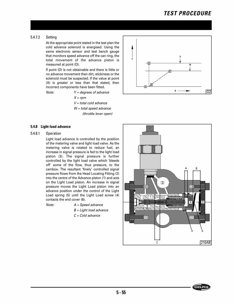
TEST PROCEDURE
5 - 55
5.4.7.2 Setting
At the appropriate point stated in the test plan the
cold advance solenoid is energised. Using the
same electronic sensor and test bench gauge
that monitors speed advance off the can ring, the
total movement of the advance piston is
measured at point (D).
If point (D) is not obtainable and there is little or
no advance movement then dirt, stickiness or the
solenoid must be suspected. If the value at point
(A) is greater or less than that stated, then
incorrect components have been fitted.
Note: Y = degrees of advance
X = rpm
V = total cold advance
W = total speed advance
(throttle lever open)
5.4.8 Light-load advance
5.4.8.1 Operation
Light load advance is controlled by the position
of the metering valve and light load valve. As the
metering valve is rotated to reduce fuel, an
increase in signal pressure is fed to the light load
piston (3). The signal pressure is further
controlled by the light load valve which ‘bleeds
off’ some of the flow, thus pressure, to the
cambox. The resultant ‘finely’ controlled signal
pressure flows from the Head Locating Fitting (2)
into the centre of the Advance piston (1) and acts
on the Light Load piston. An increase in signal
pressure moves the Light Load piston into an
advance position under the control of the Light
Load spring (5) until the Light Load screw (4)
contacts the end cover (6).
Note: A = Speed advance
B = Light load advance
C = Cold advance
G2
210AB
1
3
A B
C
5
2
64

TEST PROCEDURE
5 - 56
5.4.8.2 Setting
The same electronic sensor and test bench
gauge that monitors speed and cold advance off
the cam ring is used to set and check light load
travel. If a torque screw is not fitted as standard,
remove the plug and temporarily fit a torque
screw, lock nut and seal (1). At the test plan
stated speed hold the throttle lever open using
tool 7244-411 (2) and adjust the torque screw (1)
to a set given advance piston travel which results
in a light load fuel delivery, point (F). Point (G)
checks the setting, which can be ‘finely’ set by
adjusting transfer pressure.
To ensure the advance position does not become
retarded as the throttle lever and fuel delivery
return to full load, a further check at point (E)
ensures there is no danger of an ‘engine’ misfire.
If LLA at (F) is low, remove a shim, if high, add a
shim.
Note: Y = advance and delivery
X = rpm
U = maximum LLA
(throttle closed)
V = LLA transition
W = no LLA (throttle open)
Providing the correct advance, transfer pressure
and metering valve components have been
fitted, failure to obtain the values required can be
attributed to the control mechanisms that
determine light load advance.
Having previously confirmed that transfer
pressure is correct then the light load spring or
its shimming must be suspect. The setting of the
light load valve with resultant flow of ‘bled’ fuel
into the cambox and the seating of the HLF and
its plug against the head and rotor must also be
suspect.
5.4.9 Maximum fuel
Maximum fuel delivery is controlled by the scroll
plates, which limit the outward travel of pumping
plungers.
The position of the scroll plates is set by adjusting
the position of the carriage link plate, which is in turn
dependent on the position of the torque trimmer
cam operated by transfer pressure.
Some applications have the addition of a boost
capsule.
The diaphragm operated boost capsule, senses
engine boost pressure and changes the position of
the carriage link and scroll plates at the same time,
but independently to that set by the torque trimmer
cam.
G3
2192
2
1
2217

TEST PROCEDURE
5 - 57
5.4.10 Torque trimmer
5.4.10.1 Operation
It is necessary to adjust the position of the scroll
plates to achieve a specified delivery for a given
torque trimmer cam travel.
This is achieved by firstly setting the position and
travel of the carriage link plate relative to the
torque trimmer cam.
Transfer pressure acts directly on the torque
trimmer piston, which bears on the cam. Being
directly related to pump speed it will position the
carriage link plate for that speed.
An electronic sensor tool (1), introduced through
the access hole in the governor cover, contacts
the carriage link plate and registers that position.
An initial reading is used as a datum point and a
second position reading taken at a different
speed when the torque trimmer cam should have
travelled a set distance.
This is known as ‘Carriage Position Sensing’
(CPS).
Once the travel is confirmed as correct, but
before the scroll plates are adjusted relative to
this position to give a specified fuel delivery the
latch valve and, if fitted, the boost control, is set
using the CPS.
Once the latch valve and the optional boost
control has been set the electronic sensor is
removed and the maximum fuel adjusting tool
(1) is fitted in its place.
The tool adjusts the scroll plate position in
relation to the carriage link plate which enables
torque trimmer cam and maximum fuel delivery
relationship to be accurately set.
5.4.10.2 Setting
Note: If the pump to be tested has both featuresof torque trimmer and boost, the boost capsulemust be supplied with a compressed air pressureonly when stated on the test plan and then onlyto the value stated. Failure to do so may causebending and damage to the cam follower.
To set and check the position and travel of the
carriage link plate, the advance probe sensor,
(AE3/1) has to be converted using kit YDT264.
Note: It will not be a requirement of the testprocedure to measure the pump advance travelat the same time as the carriage position travel.Therefore the same sensor tool can be used forsetting both features.
2211
2197
1
1

TEST PROCEDURE
5 - 58
The CPS kit contains a probe pin with a magnetic
tip to maintain contact with the maximum fuel
adjusting screw, an adaptor to enable the sensor
to be screwed into the governor cover and a
return spring. (The standard spring used in AE3/1
for measuring advance movement is of a too
strong a rate and, if used, will affect the
sensitivity of the torque trimmer cam and result
in incorrect settings).
The sensor (1), once converted, is fitted carefully
through the hole in the governor cover that is
used for maximum fuel adjustment.
Note: If fitted carelessly, the probe can be locatedalongside the maximum fuel adjustment screw.In this position it will not be possible to set theCPS and the probe pin may become bent.
Refer to the Pre-Test notes to confirm that the
initial setting of the torque trimmer cam is
correct. Adjust if necessary using the special tool
(1).
Select the test bench ‘advance mm’ option and at
the speed specified in the test plan zero the CPS
sensor, point (A).
Reduce the pump speed to that specified in the
test plan and adjust the torque trimmer cam
adjuster until the CPS reading is obtained, point
(B). Further checks are made to confirm the
accuracy of the settings, points (A),(B),(C).
Note: All CPS settings are carried out underdecreasing test bench speed conditions. Thehysterisis of the system will give inaccurateresults if the bench speed is allowed to go belowthe adjusting speed and then brought back ‘up’to the speed.
Note: Y1 = delivery (mm3/st)
Y2 = CPS travel (mm)
X = rpm
G4
2207
2197
1
1
F
BA
D
C
E

TEST PROCEDURE
5 - 59
5.4.11 Boost control
5.4.11.1 Operation
A boost control device can, in addition to the
torque trimmer cam, also control the maximum
fuel delivery.
The setting of these combined features is carried
out in two stages. The torque trimmer cam
position is carried out first followed by the boost
control.
The boost control device senses the engine turbo
boost pressure through the medium of a
diaphragm. Diaphragm movement is transmitted
through a linkage pin and moves the carriage link
plate independently to any changes brought
about by torque trimmer cam movement.
5.4.11.2 Setting
Connect the boost capsule inlet (1) to a source of
dry, clean compressed air.
Note: The stroke of the boost control diaphragmshould have already been set (see section4.7.1.1).
At the specified test plan speed the CPS reading
(A) under the full boost pressure is set to zero.
A second CPS reading is taken at the same or
different speed (B), but at zero boost pressure.
The two readings confirm that the boost stroke is
correct.
Further readings taken at other points, speeds
and pressures (C) & (D) will confirm that the
boost control spring is of the correct rate.
Note: Y = boost
X = rpm
Failure to obtain the values at point (C) indicates
that the travel of the boost stroke is incorrect. The
procedure for setting the stroke must be re-
checked (see section 4.7.1.1).
Failure to obtain the values at point (B) indicates
that the boost control spring rate or shimming is
incorrect.
Note: If the torque trimmer and maximum fuelsettings have been inaccurately set, then theboost settings will also be incorrect.
G5
2214
1

TEST PROCEDURE
5 - 60
5.4.12 Latch valve
5.4.12.1 Operation
Transfer pressure operates the latch valve and is
used primarily to cut excess fuel by movement of
the torque trimmer. The latch valve is also used
to control advance. This results in there being no
speed, light load or cold advance before the
valve opens.
5.4.12.2 Setting
At the test plan stated speed, adjust the latch
valve (1) at point (A) to obtain the CPS reading
specified. Further speed checks at points (B) &
(C) will confirm the correct operation of the valve.
Remove the Sensor from the pump and convert
it back ready to measure advance.
Note: Y = CPS
X = rpm
Providing transfer and cambox pressures are
being controlled accurately, failure to obtain the
settings could be attributed to either a weak or
incorrect control spring or debris restricting fuel
flow or causing ‘stickiness’ of the valve
operation.
3448
1
G9

TEST PROCEDURE
5 - 61
5.4.13 Maximum fuel adjustment
Fit the maximum fuel adjuster tool (1).
Adjust the fuel delivery at the speed and delivery
quoted in the test plan, point (D).
The fuel delivery once set at point (D), is checked
at points, (E) and (F), which confirm torque
trimmer fuel control is correct.
Note: Y1 = delivery (mm3/st)
Y2 = CPS travel (mm)
X = rpm
Failure to obtain the CPS readings can be
attributed to:
- Incorrect fitting or sticking of the tool.
- Incorrect transfer pressure that fails to position
the torque trimmer cam relevant to the speed
required.
- The cam follower is contacting the trimmer cam
on the wrong side.
If the CPS readings are correct, but the fuel
delivery is outside the limits specified, then a
problem is indicated with the components that
set and control the outward movement of the
pumping plungers. That is; the carriage link
assembly, scroll plates, cam ring and Head and
Rotor assembly.
5.4.14 Torque screw
5.4.14.1 Operation
The natural fuel delivery curve (A), (B) can be
influenced by the position of the metering valve
so that at high speed, a pressure time fill
situation occurs. When, on decreasing engine
speed, the metering valve position is adjusted,
the full load delivery curve is altered, (C), (A).
Note: Y = delivery
X = rpm
G6
2211
1
G4
D
AC
B
F
E
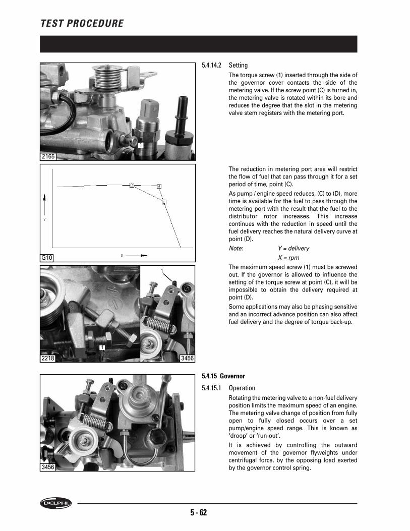
TEST PROCEDURE
5 - 62
5.4.14.2 Setting
The torque screw (1) inserted through the side of
the governor cover contacts the side of the
metering valve. If the screw point (C) is turned in,
the metering valve is rotated within its bore and
reduces the degree that the slot in the metering
valve stem registers with the metering port.
The reduction in metering port area will restrict
the flow of fuel that can pass through it for a set
period of time, point (C).
As pump / engine speed reduces, (C) to (D), more
time is available for the fuel to pass through the
metering port with the result that the fuel to the
distributor rotor increases. This increase
continues with the reduction in speed until the
fuel delivery reaches the natural delivery curve at
point (D).
Note: Y = delivery
X = rpm
The maximum speed screw (1) must be screwed
out. If the governor is allowed to influence the
setting of the torque screw at point (C), it will be
impossible to obtain the delivery required at
point (D).
Some applications may also be phasing sensitive
and an incorrect advance position can also affect
fuel delivery and the degree of torque back-up.
5.4.15 Governor
5.4.15.1 Operation
Rotating the metering valve to a non-fuel delivery
position limits the maximum speed of an engine.
The metering valve change of position from fully
open to fully closed occurs over a set
pump/engine speed range. This is known as
‘droop’ or ‘run-out’.
It is achieved by controlling the outward
movement of the governor flyweights under
centrifugal force, by the opposing load exerted
by the governor control spring.
2218
2165
1
1
3456
3456
1
G10

TEST PROCEDURE
5 - 63
5.4.15.2 Setting
With the throttle lever held in the open position,
using tool (1), the governor control spring holds
the flyweights closed and a fuel delivery reading
is taken (A).
The pump speed is increased to a pre-
determined value and by adjusting the throttle
lever stop screw (2) the governor spring load is
reduced. This reduction allows the flyweights to
start moving outwards under centrifugal force.
The metering valve closes and reduces fuel
delivery (B).
Pump speed is further increased and the fuel
delivery should be reduced to the value indicated
on the test plan (C).
Pump speed is then again re-set to a value that
will return delivery to a full load condition.
Note: Y = delivery
X = rpm
Failure to meet the points shown on the diagram
could be attributed to a ‘stiffness’ in the governor
mechanism, incorrect link length setting, or a
wrong or weak governor spring. If the pump has
seen an excessive service life then a build up of
wear on all the mechanical parts, from drive shaft
through to metering valve and throttle lever, is to
be suspected.
5.4.16 Light load valve
5.4.16.1 Operation
The Light Load Valve (1), in conjunction with the
metering valve, controls the signal pressure to
the light load piston in the advance device. This
enables the position of the advance piston to be
set for a compatible position for the amount of
fuel required for light load.
5.4.16.2 Setting
The test plan will specify a speed at which to
adjust the opening of the valve to give a pre-
determined fuel value for a given throttle
opening.
If there is difficulty in obtaining the light load fuel
deliveries to correspond to the light load advance
readings, then the accuracy of the operation of
the light load valve must be considered.
Providing metering valve and advance operation
is correct, failure to obtain the settings could be
attributed to either a weak or incorrect control
spring or debris restricting fuel flow.
3438
G8
2224
1
2
1

TEST PROCEDURE
5 - 64
G7
5.4.17 Idle setting
5.4.17.1 Operation
As well as controlling the engine at its highest
speed, the governor must also control it at its
lowest speed, idle. Without adequate control,
engine stall or surge will occur. At high speed
when the throttle lever is released, the governor
flyweights open, as the governor control spring
no longer exerts a load keeping the weights
closed. In this position the metering valve rotates
to a closed position and the engine speed falls
due to lack of fuel.
As the engine speed approaches the idling
range, the load exerted by the light idle spring
hooked around the main governor control spring
peg slowly closes the flyweights. A fine balance
then occurs between this spring and the
centrifugal force produced by the flyweights.
5.4.17.2 Setting
The idle fuel delivery must be set to a nominal
setting to ensure sufficient fuel is delivered, with
the throttle closed, to sustain idling when the
pump is first fitted to an engine.
With the test machine running at the specified
speed, adjust the idle screw (1) to achieve the
delivery (B) as quoted in the test plan. The test
machine speed is then checked at a higher speed
to ensure that the delivery reduces by the
required amount (C). This will confirm that the
governor mechanism is capable of controlling
the engine speed at idle and prevent stalling
(A),(B),(C),(D).
Note: Y = delivery
X = rpm
V = maximum fuel
(throttle open)
W = zero delivery
(throttle closed)
If the readings cannot be achieved, re-check the
link length before dismantling the governor
mechanism to investigate incorrect build,
stiffness or wear problems.
2218
1
3456
1

TEST PROCEDURE
5 - 65
5.4.18 ESOS
Checking of the ESOS, (1) is carried out at a set
speed with the solenoid de-energised and the fuel
delivery measured. A delivery in excess to that
specified indicates a faulty seat.
If there is no change in the delivery quantity, a
complete operating failure or in the case of an
energised to stop ESOS an open electrical circuit of
the ESOS must be suspected. The ESOS is non-
repairable and a complete new unit must be fitted in
its place.
After checking, the test bench must be stopped to
allow any pressure above the solenoid plunger to
disperse. Failure to do so, will prevent the plunger
rising when re-energised to permit delivery to
commence.
5.4.19 Timing
5.4.19.1 Operation
Timing is set dynamically. To do this, an
electronic pulse generated at a precise point in
drive shaft rotation is compared to a pulse
generated by the pumping action of the plungers
delivering fuel.
5.4.19.2 Setting
The Dynamic Timing kit (1), part nos. YDT261 or
YDT262 (depending on the type of test bench)
contains a special encoder coupling (2) keyed to
the pump drive shaft.
A piezo transducer (1) which is fitted into the HP
outlet (as specified on the test plan).
All parts must be connected according to the
fitting instruction contained within the kit.
The setting of the timing is then a process
controlled by the timing kit along with the
instructions contained within the test plan.
2225
1
2228
2229
2233
1
1
2

TEST PROCEDURE
5 - 66
5.5.3 Test machine drive
Caution: Before carrying out any activity on the test
machine drive arrangement ensure that the
electrical supply to the machine is switched off.
The details of pump mounting will depend upon the
type of test machine available (see section: 5.2 Test
Conditions).
The test plan includes information necessary for the
correct mounting of the pump on to the test
machine.
Fit a suitable test drive adapter for the pump drive
shaft, for dynamically timed pumps use the coupling
in kit YDT261 or YDT262 Ensure that the adaptor is
fully tightened (see section 6.1 for details of drive
adaptors).
Ensure that the test machine drive rotation is
compatible with the pump rotation.
Warning
Incorrect rotation will result in serious
damage to the pump.
Ensure that no end loading is applied to the pump
when it is fitted to the drive adaptor.
Rotate the drive by hand in the direction of normal
rotation to check that the pump is free to rotate.
Before starting the machine, check the following:
the pump is firmly secured to the mounting
the mounting is secured to the machine bed
the drive adaptor is securely clamped
5.5.4 Overcheck pre-set notes
5.5.4.1 Throttle lever
To be fully open unless otherwise stated.
5.5.4.2 Solenoids
To be energised unless otherwise stated.
5.5.4.3 Transfer Pressure
When taking a transfer pressure reading where
the test plan calls for the cambox pressure to be
included, the test bench transfer pressure gauge
must equal the sum of the transfer pressure and
cambox pressure shown in the test plan.
E.g. If the test plan states:
Test (11) Transfer Press. (C) 1200 Press. at test (8)
+ 72 to 84 psi (where test (8) is the cambox
pressure).
If cambox pressure at test (8) was 12 psi then the
transfer pressure gauge should read between 84
(72+12) to 96 psi (84+12).
5.5.4.4 Advance
The location from where the advance readings
are to be taken.
5.5 OVERCHECK PROCEDURE
5.5.1 Introduction
This facility enables the operator to quickly assess
the ability of a pump to control an engine within the
performance parameters it has been designed for
and agreed with, the Original Equipment
Manufacturer (OEM).
The pump control curves are compared at set points
with pre-determined engine performance curves
that are known to produce the required engine
performance.
It is an ideal ‘tool’ to confirm if the pump is the cause
of engine malfunction or poor performance and the
section is designed to ‘stand alone’ from the setting
plan.
It is also part of the warranty return procedure and
any guarantees pertaining to the product are based
on the results of the Overcheck plan.
Note: Pumps that are timed dynamically should bereceived with the drive shaft locked in the timedposition. This permits comprehensive diagnosticsand validation if subject to Warranty.
Providing all the values specified are achieved, the
pump will be able to maintain the original
homologated engine performance for which it is
designed. Failure to attain any one of the values will
indicate that there is a pump setting or function
failure that will require further investigation. The
setting plan can be used for this purpose.
This section is not designed as a fault diagnostic
tool, but as confirmation that the pump is, or is not
the cause of an engine fault or performance
problem.
The following notes are standard instructions that
must be applied to all pumps when being prepared
for testing. They will not be stated on any test plan
as they will be recognised as the basic standard to
adhere to. It is important that the pump is fitted to
the test bench without disturbing any of the settings.
However, on some applications settings may have
to be disturbed. In these cases, instructions during
the checking procedure will indicate when to do so.
This will be after the setting to be disturbed has
been checked and recorded.
5.5.2 Pump preperation
The pump must be drained and the fuel retained in
case of contamination.
The pump should then be leak tested.
During the test procedure, there should be no fuel
leaks from the pump.

TEST PROCEDURE
5 - 67
5.5.5 Overcheck test procedure
Pump preparation, operation and validation of
results are fully described in the appropriate SIN’s
(refer to Direct2Web CD-ROM for a full list of notes.
Note: The drive shaft for those pumps that aredynamically timed must be received and keptlocked in the timed position. This will enable theaccuracy of the pump to engine bolt-up positionto be clarified. Unlocking the drive shaft out ofthe test plan sequence will result in loosing any“as received” data and make it impossible todetermine the root cause of a bolt-upmisalignment.

TEST PROCEDURE
5 - 68

TOOLING, TORQUES & EVDS
6 - 69
Part Number Description
7244-581 Adaptor for Boost Pressure Setting (13 mm dia)
YDT140 Adaptor for Transfer Pressure & Backleak
AE3/1 Advance Probe - Requires AE7 & AE3/2
HB343 Advance Probe Adaptor Kit for use with AE3/1
AE7 Advance Probe Box - Requires AE3/1 & AE3/2
AE3/2 Advance Probe Cable - Requires AE7 & AE3/1
7244-584 Body Screw Tool for Boost Stroke Adjustment
YDB328 Boost Control Tester
HB246 Boost Pressure Control Unit for Setting Boost Pressure
YDT146 Cam Car Torx Kit
YDT264 CPS Tool
7244-582 Dial Gauge Adaptor for Boost Control
YDT136 Dial Indicator Gauge
YDB314 Digital Advance Gauge Kit
APB94 Drive Adaptor Plate (3 Hole)
APB195 Drive Adaptor Plate (68 mm)
APB194 Drive Adaptor Ring (50mm)
7244-633 Drive Shaft Seal Guide for Double Seal Fitment
YDT263 Dual Transfer Pressure Adjuster
YDT262 Dynamic Timing Kit (Stand Alone)
YDT261 Dynamic Timing Kit for AVM2 Test Bench
YDB288 Edge Filter
5936-95Q Edge Filter Washer
7244-231 Extractor for Drive Hub
7244-604 Extractor for Regulating Sleeve
AHP134 High Pressure Pipe (6 x 1.5 x 710 mm)
AHP133 High Pressure Pipe (6 x 1.8 x 450 mm)
YDB372 Hydra-clamp
AI51 Injector for AVM & PGM Test Bench - Fitted with YDB286 Nozzle
AI53 Injector for AVM & PGM Test Bench - Fitted with YDB287 Nozzle
AI52 Injector for HA2500 & HA700 Test Bench - Fitted with YDB286 Nozzle
AI54 Injector for HA2500 & HA700 Test Bench - Fitted with YDB287 Nozzle
6408-80A Max. Fuel Adjuster
YDB286 Nozzle BDL0S6844 CFE
YDB287 Nozzle BDL0S6889 CFE
YDB289 Nozzle Holder
7244-275A Pressure Gauge for Cam Box
7244-625 Protection Cap for Boost Control Pivot Plug
6.1 TOOLING

TOOLING, TORQUES & EVDS
6 - 70
Part Number Description
7244-627 Protection Cap for Boost Control Plug
7244-626 Protection Cap for Boost Control Screw Body
1804-429 Protection Cap for Housing Drain Screw / TP Advance Screw / Timing Cover Plate Plug
7244-621 Protection Cap for Latch Valve Body
7244-621A Protection Cap for Latch Valve Body
7144-458C Protection Cap for Latch Valve Body / Throttle & Exhaust Shafts
7244-623 Protection Cap for LLA Body
7244-623A Protection Cap for LLA Body
6408-68 Protection Cap for Regulating Sleeve
7044-897 Protection Cap for Solenoid & Head Locating Fitting
7244-628 Protection Cap for Torque Trimmer Piston End Cap
7244-629 Protection Cap for Torque Trimmer Spring End Cap
1804-411 Pump Mounting Plate
ALP307 Quick Fit Pipe Connection
6408-59 Retainer for Rotor Plungers
7174-62 Retaining Clip for Hydraulic Head Plungers
ALP308 Screw Fit Pipe Connection
7244-275/3 Screw for Cambox Pressure Gauge
7044-889 Socket for TP Rotor
7244-24 Spanner for Holding Drive Hub
7244-411 Throttle Lever Movement Gauge
7244-405 Throttle Spring Assy Tool
6408-78 Torque Trimmer Adjuster
7244-439A Torx Bit T10 for Timing Plate Screw
7244-439 Torx Bit T15 for Timing Plate Screw
7244-437 Torx Bit T20 for Catch Plate Screw
7244-438 Torx Bit T25 for Governor Control Cover Screw
YDT146 Tamper-resist Torx bit kit
60620197 Dismantling tray available through Delphi Diesel Systems, Aftermarket Operations,
Service Operations Department

TOOLING, TORQUES & EVDS
6 - 71
NM LBF.IN
LSN Description Part Number from to from to Head Type Comments
101 Drive Shaft Nut 7185-758 90.00 90.00 796 796 22mm AF
120 Catch Plate Screw 7174-350A 4.00 4.00 35 35 T15
123 Cam Ring Screw 7189-086 57.00 57.00 500 500 14mm AF
130 Transfer Pump Rotor 7182-245 7.40 7.40 65 65 Special
140 Endplate Screw 7185-015 5.10 5.10 45 45 4mm Allen
203 Latch Valve Assy 7185-884A 34.00 34.00 300 300 17mm AF for tightening sequence refer to manual
210 Blanking Plug 9101-335 5.50 5.50 48 48 5mm Allen
214 LLA Valve Body 7189-008 34.00 34.00 300 300 22mm AF
221 Stop Solenoid 7185-900H 15.00 15.00 130 130 24mm AF
224 Inlet Connection 7189-066 34.00 34.00 300 300 24mm AF
237 Clamping Plate Nut 7185-852A 30.40 30.40 270 270 18mm AF
238 Bracket Screw 7167-667A 14.00 14.00 120 120 5mm Allen
239 Delivery Valve Holder 7185-130D 8.00 12.00 70 103 16mm AF turn 65° ±5° (max 45.5Nm ±17.0 Nm)
245 Housing Plug Bolt 7167-299 2.30 2.30 20 20 5/16" AF
247 Drive Shaft Lock Screw 7189-003 17.00 17.00 150 150 10mm AF drive shaft locked position
12.00 12.00 106 106 10mm AF drive shaft unlocked position - engine run
301 CA Housing Screw 7185-304A 9.50 9.50 85 85 4mm Allen
305 Light Load Screw 7189-096DQ 9.00 9.00 80 80 14mm AF
316 Nut 7185-854B 2.30 2.30 20 20 8mm AF
319 Solenoid 7185-900K 15.00 15.00 130 130 24mm AF
324 Head Locating Fitting 7189-010 40.00 40.00 350 350 3/4” AF for tightening sequence refer to manual
325 Housing Stud Cap Nut 5330-362C 28.00 28.00 240 240 1/2” AF
401 Control Bracket Screw 7174-798 2.30 2.30 20 20 2.5mm Allen
402 Control Bracket Screw 7174-798 2.30 2.30 20 20 2.5mm Allen
403 Control Bracket Screw 7182-023A 5.10 5.10 45 45 8mm AF
411 Control Bracket Bolt 7182-023 5.10 5.10 45 45 8mm AF
415 Backleak Adaptor 7189-142A 25.00 25.00 220 220 17mm AF
417 Governor Cover Screw 7174-895C 4.00 4.00 35 35 T25
503 Pivot Plug 7185-316 16.65 20.35 146 176 6mm Allen
504 Boost Cover Bolt 7185-645 2.30 2.30 20 20 Torx special
511 Adjusting Screw Body 7185-954 29.50 29.50 260 260 Special
519 Banjo and Pipe 7189-148 6.80 6.80 60 60 12mm AF
521 Gov Cover Plug Screw 7185-641 6.30 7.70 56 68 Torx special
522 Self Lock Nut 7174-637 5.70 5.70 50 50 10mm AF
537 Gov Cover Plug Screw 7182-569A 5.10 5.10 45 45 10mm AF
542 Idle Screw Lock Nut 7185-854E 5.70 5.70 50 50 10mm AF
547 Tamper Proof Nut 7189-040 6.20 6.20 55 55 13mm AF
6.2 TORQUE VALUES

TOOLING, TORQUES & EVDS
6 - 72

TOOLING, TORQUES & EVDS
6 - 73

TOOLING, TORQUES & EVDS
6 - 74

TOOLING, TORQUES & EVDS
6 - 75

TOOLING, TORQUES & EVDS
6 - 76

Whilst every care has been taken in compiling the information in this publication, Delphi Diesel Systems Ltd. cannot accept legal liability for any inaccuracies.
Delphi Diesel Systems Ltd. has an intensive programme of design and development which may well alter product specification. Delphi Diesel Systems Ltd.
reserve the right to alter specifications without notice and whenever necessary to ensure optimum performance from its product range.
All Rights Reserved
No part of this publication may be reproduced, stored in a retrieval system, or transmitted in any form, or by any means, electronic, mechanical, photocopying,
recording or otherwise, without the prior permission of Delphi Diesel Systems Ltd.
Il a été apporté une attention particulière pour garantir l'exactitude des renseignements contenus dans cette publication par Delphi Diesel Systems Ltd, mais
la société décline toute responsabilité légale à cet égard. Delphi Diesel Systems Ltd poursuit un programme intensif de conception et de développement qui
peut entraîner la modification des spécifications des produits. Delphi Diesel Systems Ltd se réserve le droit de modifier les spécifications, sans préavis et si
cela est nécessaire, pour assurer les performances optimales de sa gamme de produits.
Tous droits réservés
Toute reproduction, mémorisation dans un système informatique ou transmission sous quelle que forme que ce soit, ou par tout moyen électronique,
mécanique, par photocopie, enregistrement ou autre de cette publication est interdit sans l'autorisation préalable de Delphi Diesel Systems Ltd.
Bei der Zusammenstellung der in dieser Veröffentlichung enthaltenen Informationen wurde mit größtmöglicher Sorgfalt vorgegangen. Delphi Diesel Systems
Ltd. kann jedoch rechtlich nicht für etwaige Ungenauigkeiten zur Verantwortung gezogen werden. Delphi Diesel Systems Ltd. führt ein fortlaufendes Design-
und Entwicklungsprogramm durch, weshalb es möglich ist, daß sich Produktdaten ändern. Delphi Diesel Systems Ltd. behält sich das Recht vor, ohne
Vorankündigung Spezifikationen jederzeit zu ändern, um die optimale Leistung seiner Produkte sicherzustellen.
Alle Rechte vorbehalten.
Kein Teil dieser Veröffentlichung darf ohne vorherige Genehmigung durch Delphi Diesel Systems Ltd. abgedruckt, in einem Datenverarbeitungssystem
gespeichert oder auf irgendeine Art und Weise, sei es auf elektronischem oder mechanischem Wege, durch Fotokopieren, Aufzeichnen oder auf sonstige Art,
übertragen werden.
Anche se ogni cura è stata adottata nel compilare le informazioni di questa pubblicazione, Delphi Diesel Systems Ltd. Declina qualsiasi responsabilità per eventuali
imprecisioni.
Delphi Diesel Systems svolge un intenso programma di progettazione e sviluppo che potrebbe modificare le specifiche del prodotto. Delphi Diesel Systems si riserva
il diritto di modificare le specifiche senza preavviso e ogniqualvolta lo ritenga necessario ai fini di assicurare le prestazioni ottimali dalla sua gamma di prodotti.
Tutti i diritti riservati
Nessuna parte di questa pubblicazione può essere riprodotta, memorizzata in un sistema elettronico o trasmessa in qualsiasi forma o con qualsiasi mezzo, elettronico,
di fotocopiatura, di registrazione o altro, senza la preventiva autorizzazione di Delphi Diesel Sistems Ltd.
Aunque hemos tomado todas las precauciones necesarias al recopilar esta publicación, Delphi Diesel Systems Ltd no acepta ninguna responsabilidad legal
por inexactitudes que puedan aparecer en la misma. En Delphi Diesel Systems Ltd se sigue un programa intensivo de diseño e investigación el cual podría
en cualquier momento alterar la especificación de los productos. Delphi Diesel Systems Ltd se reserva el derecho de alterar las especificaciones sin
notificación previa y siempre que esto sea necesario para asegurar el mejor funcionamiento posible de sus productos.
Todos los Derechos Reservados
No se permite copiar, almacenar en sistema recuperable ni transmitir esta publicación de ninguna forma o medio electrónico, mecánico, de fotocopia,
grabación o cualquier otro, sin autorización previa de Delphi Diesel Systems Ltd.
Ainda que se tenha lido o máximo cuidado na compilação da informação contida nesta publicação, a Delphi Diesel Systems Ltd, não pode aceitar qualquer
responsabilidade legal por inexactidões. A Delphi Diesel Systems Ltd. tem um programa intensivo de projecto e desenvolvimento que pode porventura alterar
as especificações do produto. A Delphi Diesel Systems Ltd. reserva o direito de alterar especificações sem aviso e sempre que seja necessario para
assegurar um desempenho óptimo da sua linha de produtos.
Todos os direitos reservados.
Nenhuma parte desta publicação pode ser reproduzida, armazenada num sistema de onde possa ser recuperada ou transmitida de alguma forma, ou por
quaisquer meios, electrónico, mecânico, de fotocópia, gravação ou outros, sem autorização antecipada de Delphi Diesel Systems Ltd.