14004 evans head airpark - servicing strategy … versions\14004 evans head airpark - servicing...
TRANSCRIPT
FS 555072
121 Bridge Street P 02 6762 4411 F 02 6762 4412
PO Box 1568 E [email protected]
Tamworth NSW 2340 W www.mitchelhanlon.com.au
EVANS HEADAIRPARK PTY LTD
SERVICINGSTRATEGY
For proposed
AIRPARK DEVELOPMENTEvans Head Aerodrome
Memorial Airport Drive
Evans Head NSW 2473
Prepared for: Evans Head Airpark Pty Ltd
GPO Box 7122
Brisbane QLD 4001
Our reference: 14004
Evans Head Airpark, Servicing Strategy Page 2
Mitchel Hanlon Consulting Pty Ltd
121 Bridge Street
PO Box 1568TAMWORTH NSW 2340Phone: (02) 6762 4411 Fax: (02) 6762 [email protected]
This document may only be used for the purpose for which it wascommissioned and in accordance with the Terms of Engagement for thecommission. This document is not to be used or copied without the writtenauthorisation of Mitchel Hanlon Consulting Pty Ltd or Evans Head AirparkPty Ltd.
Ref.: 14004
FS 555072

Evans Head Airpark, Servicing Strategy Page 3
ISSUE VER. DATE AUTHOR APPROVED ISSUEDTO
01 Final 27 June 2016 T McLean M Hanlon General issue
File path: J:\2014\14004 Evans Head Airpark - Concept plan, DA & Engineering\01 Planning\Servicing\02Working Versions\14004 Evans Head Airpark - Servicing Strategy_Working v03 Rev 1.doc
Evans Head Airpark, Servicing Strategy Page 4
CONTENTS
Mitchel Hanlon Consulting Pty Ltd..................... 2
Introduction ............................................... 6
The Proponent ................................................................................................ 7
Development Overview................................................................................... 7
Site Description......................................... 1
General ........................................................................................................... 1
Stormwater Drainage...................................................................................... 2
Water Supply .................................................................................................. 3
Sewerage........................................................................................................ 4
Proposed Development ............................ 5
Stormwater ............................................... 6
Introduction ..................................................................................................... 6
Proposed Assessment Method....................................................................... 7
Concept Stormwater Network......................................................................... 7
Water Supply ............................................ 9
Introduction ..................................................................................................... 9
Design Criteria ................................................................................................ 9
Water Supply Capacity ................................................................................. 12
Concept Internal Water Supply..................................................................... 14
Sewer...................................................... 15
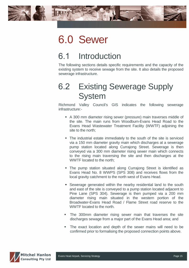
Introduction ................................................................................................... 15
Existing Sewerage Supply System............................................................... 15
Projected Equivalent Tenements and Sewage Flows .................................. 16
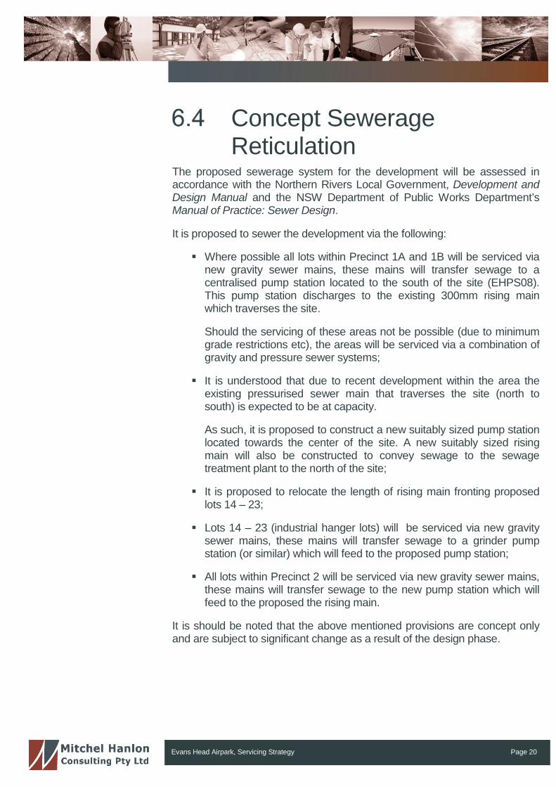
Concept Sewerage Reticulation ................................................................... 20
Stormwater Quality ................................. 22
References ............................................. 24

Evans Head Airpark, Servicing Strategy Page 5
FIGURESFigure 1: Regional Locality Plan .............................................................. 9
Figure 2: Evans Head Locality Plan ....................................................... 10
Figure 3: Overall Concept Plan .............................................................. 11
Figure 4: Overall Concept Plan .............................................................. 12
Figure 5: Concept Plan: Precinct 1A (Residential) ................................ 13
Figure 6: Concept Plan: Precinct 1B (Hanger) ...................................... 14
Figure 7: Concept Plan: Precinct 2 (Museum) ...................................... 15
TABLESTable 1: Site Identification....................................................................... 1
Table 2: Water Design Criteria.............................................................. 10
Table 3: AS 2419.1-2005 Fire Hydrant Outlet Flow Rates andPressures ................................................................................ 12
Table 4: Available Flow Rates and Pressures – 100mm and150mm Diameter DICL............................................................ 13
Table 5: Calculation of Development Design Loading........................... 17
Table 6: Sewerage Flows from the Development.................................. 18
Table 7: Stormwater Quality Targets..................................................... 23
Evans Head Airpark, Servicing Strategy Page 6
IntroductionMitchel Hanlon Consulting Pty Ltd has been engaged by Evans HeadAirpark Pty Ltd (EHAP) to prepare a servicing strategy for the proposed re-development of the Evans Head aerodrome facility. The development site isidentified as Lot 3 in DP 1217074.
The primary focus of this report is to detail the proposed servicing of the sitewith respect to:
(a) Stormwater;
(b) Water Supply; and
(c) Sewerage.
The proposal aims to develop a range of allotments and other facilitiestargeted towards the aviation enthusiasts by establishing a residentialairpark. The proposal includes:
Local commercial and recreational aerodrome;
Small scale commercial uses and community facilities associatedwith the aerodrome;
Museum for military aviation and community groups;
Residential airside precinct with direct access to flying facilities;
Aircraft maintenance and support hub; and
Boutique hotel and convention centre
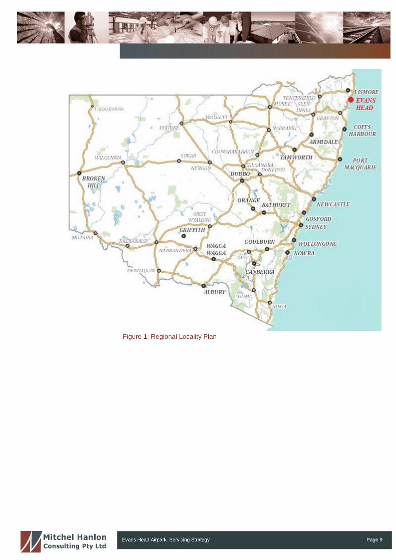
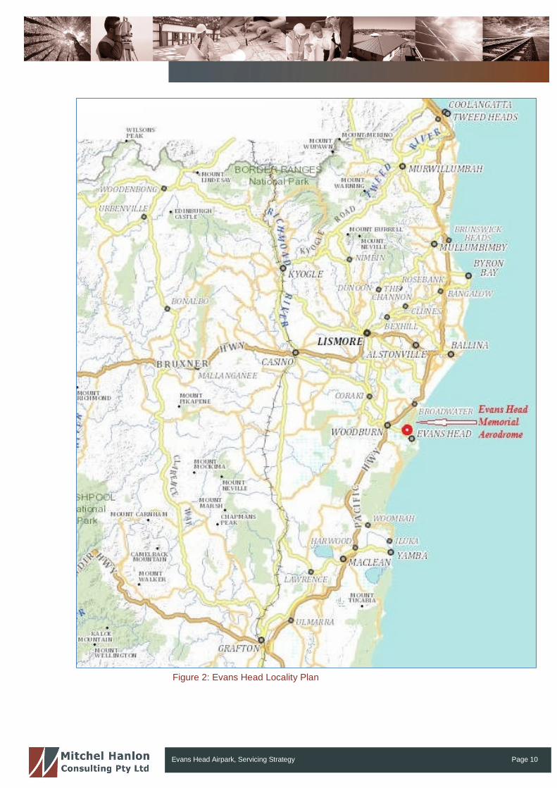
The regional context in which the development is situated is illustrated inFigure 1, while Figure 2 shows the site location within the locality of EvansHead. The proposed development is illustrated on an aerial photograph inFigure 3 and Figure 4.
Evans Head Airpark, Servicing Strategy Page 7
The ProponentThe proponent for the development is Evans Head Airpark Pty Ltd(http://www.evansheadairpark.com.au).
Evans Head Airpark Pty Ltd is a company which has been established onbehalf of the airpark proponents. Evans Head Airpark Pty Ltd are a group ofpassionate aviators and supporters of the aviation industry with a vision topreserve the heritage value and significance of the Evans Head MemorialAerodrome.
The members have been specifically drawn together for this project throughtheir mutual love for aviation and desire to see the heritage-listed EvansHead Memorial Aerodrome not only preserved but significantly contributingto the economic viability of the region and local community, once again.
Development OverviewEHAP proposes to develop a multifaceted residential and commercialAirpark on the historically significant, State Heritage Listed, Evans HeadMemorial Aerodrome.
At present the aerodrome is supported by voluntary organisations and thelocal council, with very little income being derived for its own upkeep. Withself-sufficiency a high priority for the developer of the land, the proposedAirpark provides the opportunity to not only conserve the aerodrome forcontinued use in general aviation, but also bring substantial economic andlifestyle benefits to the local and greater community.
With the creation of a residential and commercial airpark, aviation relatedindustries would be enticed to the area to start businesses and increase thenumber and range of employment opportunities. With an aviation centresuch as this, more job opportunities are open to local youth, not only inaviation, apprenticeships, building, etc, but also in tourism related industries.
With this in mind, Evans Head Airpark Pty Ltd is also determined to keepand pay homage to the significance of the aerodromes military history, bothout of respect to the part the aerodrome played in World War II, but also outof respect to the relatives and friends of our men and women who workedand played there in times of war. This goal will be achieved with the creationof a military museum similar to the Temora and Point Cook aviationmuseums.
It would initially be built around the last surviving Bellman Hangar, eventuallyleading to the creation of a very large scale museum with a strong RAAFtheme in line with its heritage. The Evans Head Memorial AerodromeCommittee and the local community would be consulted and invited to takean active role in the nature and operation of such a museum.
Evans Head Airpark, Servicing Strategy Page 8
The proposal incorporates the following key elements:
Local commercial and recreational aerodrome;
Small scale commercial uses and community facilities associatedwith the aerodrome;
Military Aviation museum;
Residential airside precinct with direct access to flying facilities;
Aircraft maintenance and support hub;
Boutique motel and convention centre; and
Standard residential release area.
Evans Head Airpark Pty Ltd believe a residential and commercial airparkfacility, with its aviation focus and historical significance, is unique and willattract a more varied clientele that can only be of added value to theresidents of the Richmond Valley. This airpark will bring added prosperityand significance to the Evans Head area and distinguish it from the usualdevelopment often found in coastal towns.
Evans Head Airpark, Servicing Strategy Page 9
Figure 1: Regional Locality Plan
Evans Head Airpark, Servicing Strategy Page 10
Figure 2: Evans Head Locality Plan
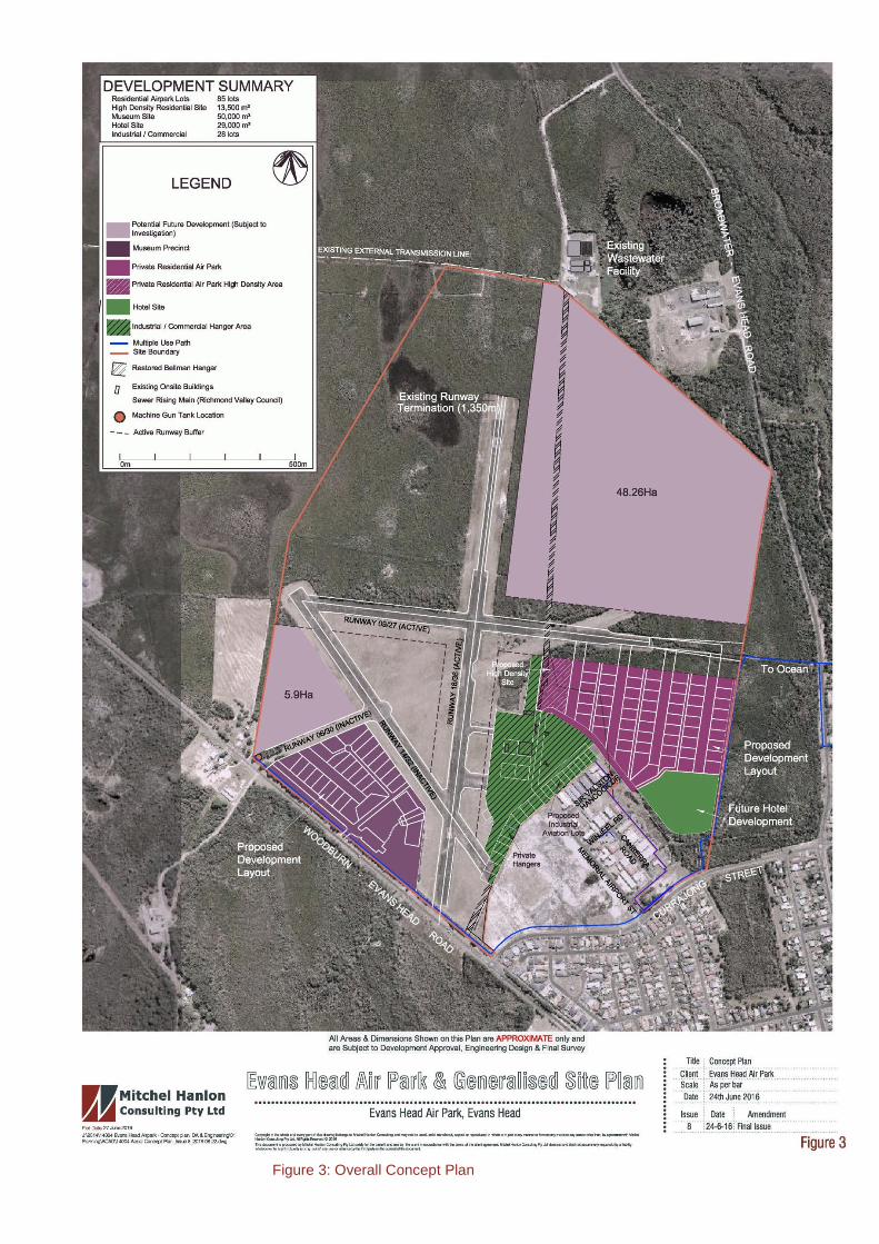
Figure 3: Overall Concept Plan
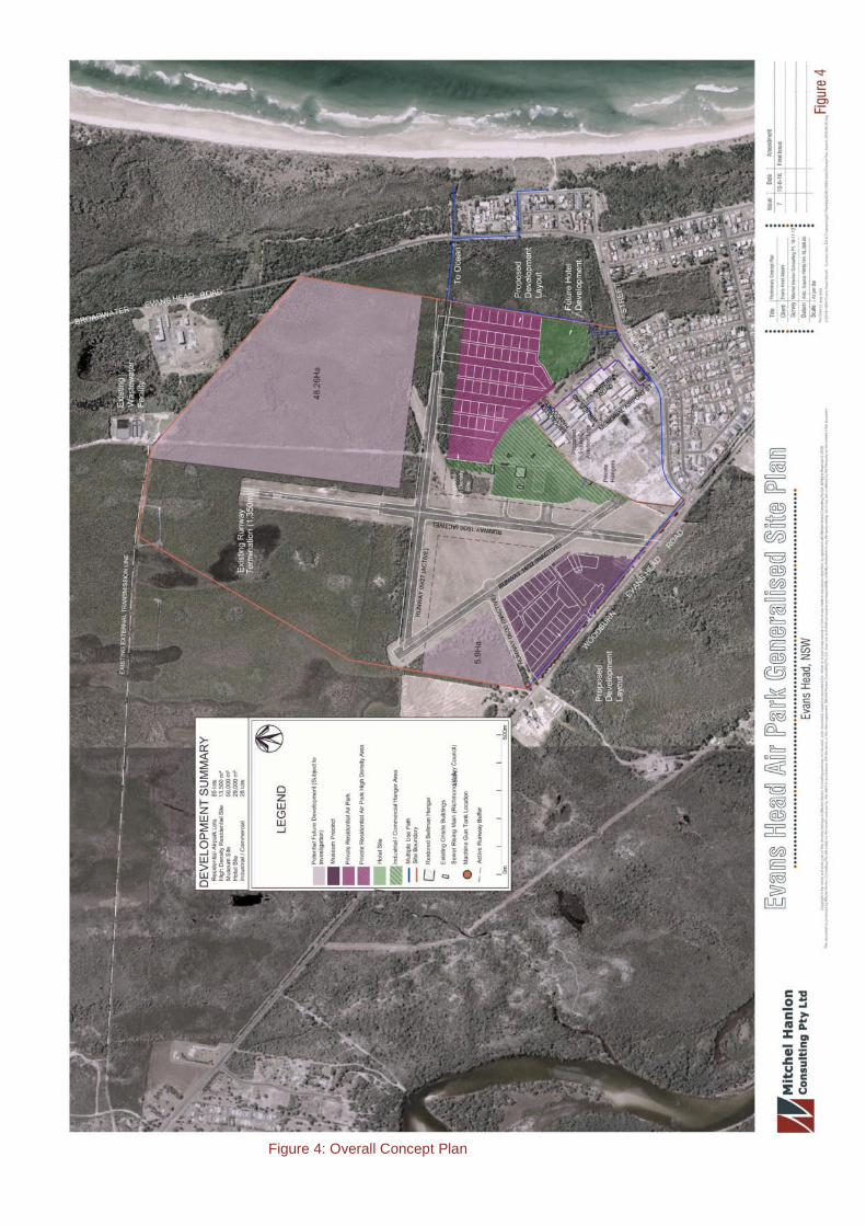
Figure 4: Overall Concept Plan
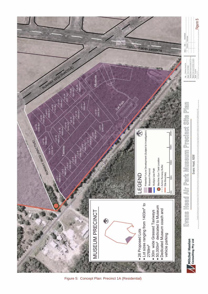
Figure 5: Concept Plan: Precinct 1A (Residential)

Figure 6: Concept Plan: Precinct 1B (Hanger)
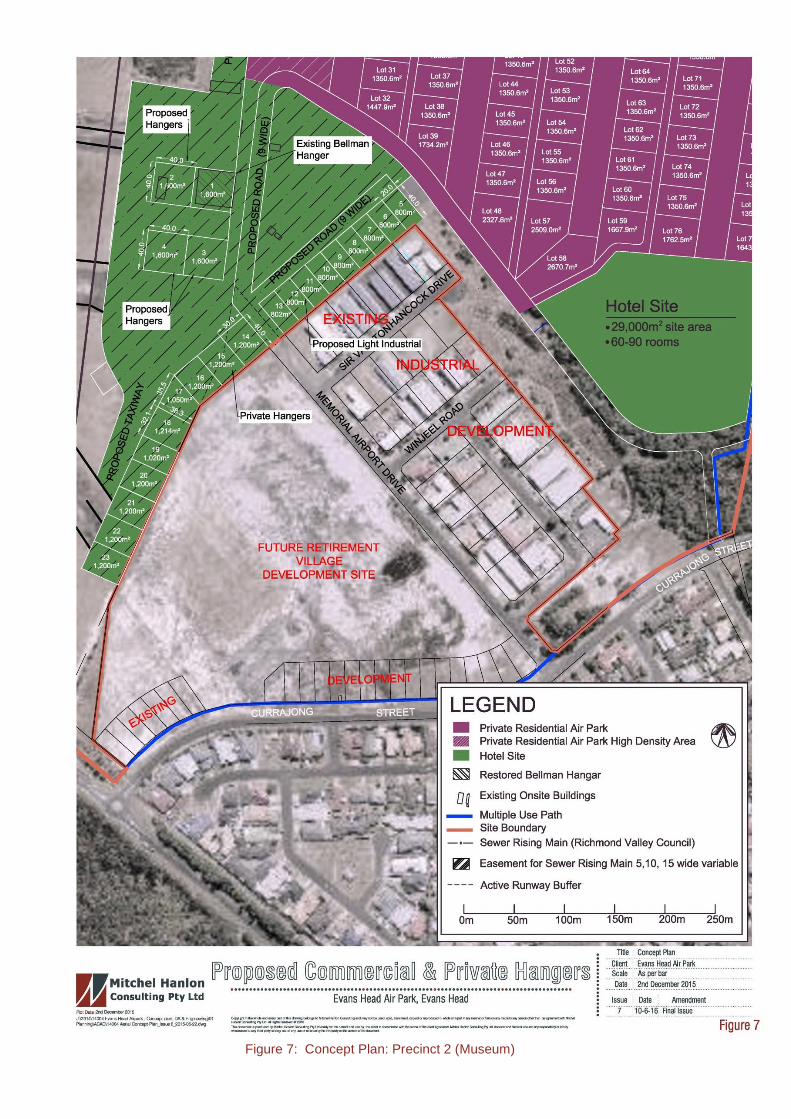
Figure 7: Concept Plan: Precinct 2 (Museum)
Evans Head Airpark, Servicing Strategy Page 1
Site Description
GeneralThe proposed development site is located along the Woodburn-Evans HeadRoad approximately 1.5 km north-west of the centre of Evans Head. Specificdetails of the subject land are included in Table 1 (p1).
Table 1: Site Identification
ASPECT DESCRIPTION
Site Owner Richmond Valley Council
Site Address Memorial Airport Drive, Evans Head
Lot / Section / DP 3 / 1217074
Town / City Evans Head
Parish Riley
County Richmond
LGA Richmond Valley
Approximate Site Area 183.6 Ha
Current Zoning * RU1 – ‘Primary Production’ and E3 –‘Environmental Management’
Current Use Evans Head Memorial Aerodrome
Site Information Sourced from ACS Title Search* Zoning under Richmond Valley LEP (2012)
The existing memorial aerodrome site is characterised by World War IIaviation infrastructure, including four runways, associated taxi-way andaprons as well as a number of hangars, including a recently restoredBellman Hangar.
Vegetation is extensively present within the site, with large patches of nativeheath vegetation located within the northern half of the site, with patchesextending across the southern half of the site in areas not occupied byaviation infrastructure.
The site is bound by the Woodburn-Evans Head Road and Currajong Streeton the south-western and south-eastern sides respectively. Land to thenorth, north-west and east of the site has been identified as the northernextents of the Broadwater National Park.
Evans Head Airpark, Servicing Strategy Page 2
The area surrounding the site contains a small pocket of industrial landlocated immediately south of the site (along the eastern side of MemorialAirport Drive). The Evans Head Waste Transfer Station and WastewaterTreatment Facility are located immediately to the north, the remaining landsurrounding the site is either residential land or National Parks and NatureReserves.
In general, much of the original road network within the surrounding areawas constructed to urban standards viz. two-lane carriageways, roll typekerb and guttering and stormwater drainage infrastructure however someroads (Broadwater-Evans Head Road / Flame Street) possess a grassedshoulder on the western verge of the road.
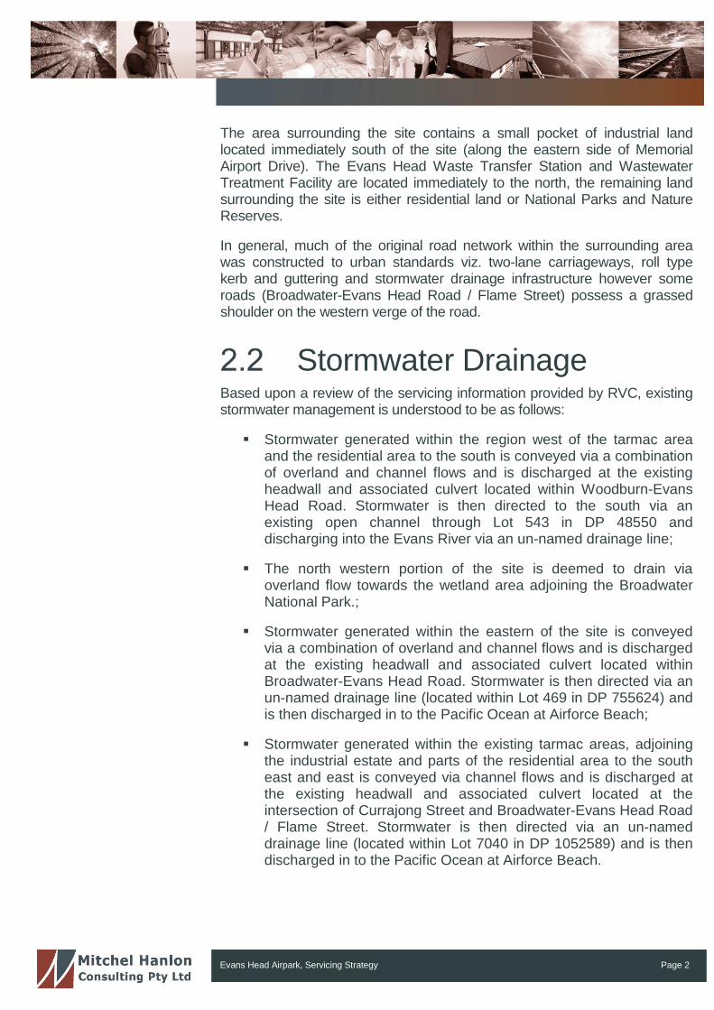
Stormwater DrainageBased upon a review of the servicing information provided by RVC, existingstormwater management is understood to be as follows:
Stormwater generated within the region west of the tarmac areaand the residential area to the south is conveyed via a combinationof overland and channel flows and is discharged at the existingheadwall and associated culvert located within Woodburn-EvansHead Road. Stormwater is then directed to the south via anexisting open channel through Lot 543 in DP 48550 anddischarging into the Evans River via an un-named drainage line;
The north western portion of the site is deemed to drain viaoverland flow towards the wetland area adjoining the BroadwaterNational Park.;
Stormwater generated within the eastern of the site is conveyedvia a combination of overland and channel flows and is dischargedat the existing headwall and associated culvert located withinBroadwater-Evans Head Road. Stormwater is then directed via anun-named drainage line (located within Lot 469 in DP 755624) andis then discharged in to the Pacific Ocean at Airforce Beach;
Stormwater generated within the existing tarmac areas, adjoiningthe industrial estate and parts of the residential area to the southeast and east is conveyed via channel flows and is discharged atthe existing headwall and associated culvert located at theintersection of Currajong Street and Broadwater-Evans Head Road/ Flame Street. Stormwater is then directed via an un-nameddrainage line (located within Lot 7040 in DP 1052589) and is thendischarged in to the Pacific Ocean at Airforce Beach.
Evans Head Airpark, Servicing Strategy Page 3
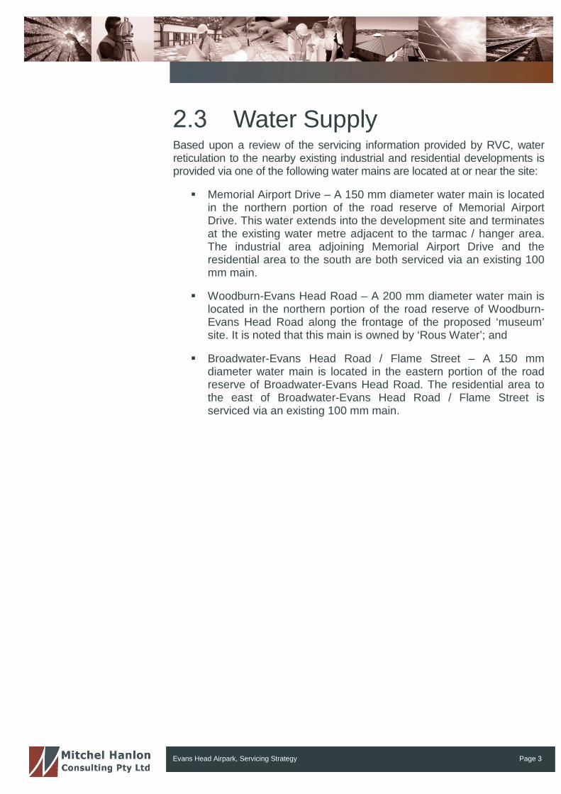
Water SupplyBased upon a review of the servicing information provided by RVC, waterreticulation to the nearby existing industrial and residential developments isprovided via one of the following water mains are located at or near the site:
Memorial Airport Drive – A 150 mm diameter water main is locatedin the northern portion of the road reserve of Memorial AirportDrive. This water extends into the development site and terminatesat the existing water metre adjacent to the tarmac / hanger area.The industrial area adjoining Memorial Airport Drive and theresidential area to the south are both serviced via an existing 100mm main.
Woodburn-Evans Head Road – A 200 mm diameter water main islocated in the northern portion of the road reserve of Woodburn-Evans Head Road along the frontage of the proposed ‘museum’site. It is noted that this main is owned by ‘Rous Water’; and
Broadwater-Evans Head Road / Flame Street – A 150 mmdiameter water main is located in the eastern portion of the roadreserve of Broadwater-Evans Head Road. The residential area tothe east of Broadwater-Evans Head Road / Flame Street isserviced via an existing 100 mm main.
Evans Head Airpark, Servicing Strategy Page 4
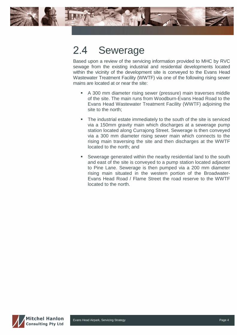
SewerageBased upon a review of the servicing information provided to MHC by RVCsewage from the existing industrial and residential developments locatedwithin the vicinity of the development site is conveyed to the Evans HeadWastewater Treatment Facility (WWTF) via one of the following rising sewermains are located at or near the site:
A 300 mm diameter rising sewer (pressure) main traverses middleof the site. The main runs from Woodburn-Evans Head Road to theEvans Head Wastewater Treatment Facility (WWTF) adjoining thesite to the north;
The industrial estate immediately to the south of the site is servicedvia a 150mm gravity main which discharges at a sewerage pumpstation located along Currajong Street. Sewerage is then conveyedvia a 300 mm diameter rising sewer main which connects to therising main traversing the site and then discharges at the WWTFlocated to the north; and
Sewerage generated within the nearby residential land to the southand east of the site is conveyed to a pump station located adjacentto Pine Lane. Sewerage is then pumped via a 200 mm diameterrising main situated in the western portion of the Broadwater-Evans Head Road / Flame Street the road reserve to the WWTFlocated to the north.
Evans Head Airpark, Servicing Strategy Page 5
ProposedDevelopment
The overall concept plan for the development is depicted in Figure 3 andFigure 4. Detailed concept plans for the residential, hanger and museumprecincts are illustrated in Figure 5, Figure 6 and Figure 7 respectively. Theproposed Airpark development is comprised of the following:
85 residential lots ranging from approximately 1,350m2 to 2,900m2;
60 – 90 room Hotel;
18 Commercial Aviation Premises;
10 Private Hangar Space;
Historical Museum; and
Club rooms.
The estate will require the provision of the following services:
(a) Stormwater drainage;
(b) Water supply; and
(c) Sewerage.

Evans Head Airpark, Servicing Strategy Page 6
Stormwater
IntroductionStormwater impacts due to the development will be assessed using thefollowing criteria:
a) Using methodologies detailed in Australian Rainfall and Runoff(2001), the following will be determined:
o Major catchment boundaries and areas;
o Existing trunk drainage flows for the 5-year, 10-year (whereappropriate) and 100-year Annual Recurrence Interval (ARI)event; and
o The development flows for the 5-year, 10-year and 100-yearARI event.
b) Assessment and recommendations will be made for:
o Capabilities of the existing trunk drainage lines; and
o Culvert/pipe size based on load requirements.
The deliverables are as follows:
a) A drainage assessment report comprised of the following:
o Runoff methodology adopted and resulting calculations.
b) Design plans that show:
o The extent of site catchments;
o Sites of existing and proposed stormwater infrastructure; and
o Ultimate discharge point(s).
Evans Head Airpark, Servicing Strategy Page 7
Proposed AssessmentMethod
Catchment areas will be defined from GIS data supplied by Richmond ValleyCouncil and a survey completed by Mitchel Hanlon Consulting Pty Ltd.
Discharge volumes for the five (5), ten (10) and one hundred (100) yearaverage recurrence intervals (ARI) will be determined using the RationalMethod as detailed in Australian Rainfall and Runoff (2001).
The stormwater management system will be designed to control stormwaterrunoff for the five (5) year ARI for the residential areas and the ten (10) yearstorm event for the industrial / commercial / hotel and museum components.The calculations will be based upon the Evans Head IFD values and runoffcoefficients obtained from the Northern Rivers – Local Government‘Development Design Specification, D5 – Stormwater Drainage Design’,2013.
The design will be developed to ensure all stormwater produced by theproposed development is contained within the site area before flowingthrough the proposed piped drainage system before entering existingstormwater drainage lines.
Concept StormwaterNetwork
Pipe flow within the industrial site will be determined for the 5-year and 10-year (where necessary) ARIs.
It is intended to develop a network of pits and drainage lines to carry alldeveloped runoff from the proposed development during a 5-year (residentialareas) and 10-year (commercial/industrial/hotel and museum areas) ARIrainfall event.
A series of overland flow paths have will also be designed to cater forstormwater surcharging for the piped network in the event of a 1 in 100 yearstorm event. It is intended that all internal roads and taxi ways will function asoverland channels directing flows to existing discharge points. The capacityof these discharge points will be confirmed during the design phase. Shouldthese points be found to be at capacity or ‘under-sized’ suitableaugmentations or upgrades will be undertaken.

Evans Head Airpark, Servicing Strategy Page 8
The principal discharge point for the eastern portion of the site has beenidentified as the existing channel located on the eastern side of Broadwater-Evans Head Road / Flame Street whilst the secondary discharge point is theexisting culvert beneath the intersection Evans Head Road / Flame Streetand Currajong Street.
The principal discharge point for the western portion of the site has beenidentified as the existing culvert located beneath Woodburn-Evans HeadRoad.
It is should be noted that the above mentioned provisions are concept onlyand are subject to significant change as a result of the design phase.
Evans Head Airpark, Servicing Strategy Page 9
Water Supply
IntroductionThe water supply to the site will be supplied from the extension of theexisting network. The following sections detail specific requirements and thecapacity of the existing system to deliver water to the site. It also details theproposed site water supply infrastructure.
Design CriteriaDesign criteria are provided by Richmond Valley Council and StandardsAustralia:
Standards Australia 2005, AS 2419.1 Fire Hydrant InstallationsPart 1: System design, installation and commissioning, ISBN 07337 7010 X.
Northern Rivers Local Government, Development and DesignManual – D11, Water Supply, Version 3; and
Water Services Association of Australia’s (WSA) publication WSA03 – Water Supply Code of Australia.
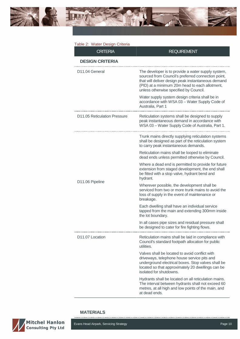
Table 2 details the relevant requirements from the Northern Rivers LocalGovernment, Development and Design Manual with respect to waterdemand, minimum static head, main pipe size and pipe fittings.
Evans Head Airpark, Servicing Strategy Page 10
Table 2: Water Design Criteria
CRITERIA REQUIREMENT
DESIGN CRITERIA
D11.04 General The developer is to provide a water supply system,sourced from Council’s preferred connection point,that will deliver design peak instantaneous demand(PID) at a minimum 20m head to each allotment,unless otherwise specified by Council.
Water supply system design criteria shall be inaccordance with WSA 03 – Water Supply Code ofAustralia, Part 1
D11.05 Reticulation Pressure Reticulation systems shall be designed to supplypeak instantaneous demand in accordance withWSA 03 – Water Supply Code of Australia, Part 1.
D11.06 Pipeline
Trunk mains directly supplying reticulation systemsshall be designed as part of the reticulation systemto carry peak instantaneous demands.
Reticulation mains shall be looped to eliminatedead ends unless permitted otherwise by Council.
Where a dead end is permitted to provide for futureextension from staged development, the end shallbe fitted with a stop valve, hydrant bend andhydrant.
Wherever possible, the development shall beserviced from two or more trunk mains to avoid theloss of supply in the event of maintenance orbreakage.
Each dwelling shall have an individual servicetapped from the main and extending 300mm insidethe lot boundary.
In all cases pipe sizes and residual pressure shallbe designed to cater for fire fighting flows.
D11.07 Location Reticulation mains shall be laid in compliance withCouncil's standard footpath allocation for publicutilities.
Valves shall be located to avoid conflict withdriveways, telephone house service pits andunderground electrical boxes. Stop valves shall belocated so that approximately 20 dwellings can beisolated for shutdowns.
Hydrants shall be located on all reticulation mains.The interval between hydrants shall not exceed 60metres, at all high and low points of the main, andat dead ends.
MATERIALS
Evans Head Airpark, Servicing Strategy Page 11
CRITERIA REQUIREMENT
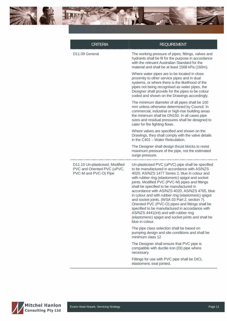
D11.09 General The working pressure of pipes, fittings, valves andhydrants shall be fit for the purpose in accordancewith the relevant Australian Standard for thematerial and shall be at least 1568 kPa (160m).
Where water pipes are to be located in closeproximity to other service pipes and in dualsystems, or where there is the likelihood of thepipes not being recognised as water pipes, theDesigner shall provide for the pipes to be colourcoded and shown on the Drawings accordingly.
The minimum diameter of all pipes shall be 100mm unless otherwise determined by Council. Incommercial, industrial or high-rise building areasthe minimum shall be DN150. In all cases pipesizes and residual pressures shall be designed tocater for fire fighting flows.
Where valves are specified and shown on theDrawings, they shall comply with the valve detailsin the C401 – Water Reticulation.
The Designer shall design thrust blocks to resistmaximum pressure of the pipe, not the estimatedsurge pressure.
D11.10 Un-plasticised, ModifiedPVC and Oriented PVC (uPVC,PVC-M and PVC-O) Pipe
Un-plasticised PVC (uPVC) pipe shall be specifiedto be manufactured in accordance with AS/NZS4020, AS/NZS 1477 Series 2, blue in colour andwith rubber ring (elastomeric) spigot and socketjoints. Modified PVC (PVC-M) pipes and fittingsshall be specified to be manufactured inaccordance with AS/NZS 4020, AS/NZS 4765, bluein colour and with rubber ring (elastomeric) spigotand socket joints. (WSA 03 Part 2, section 7).Oriented PVC (PVC-O) pipes and fittings shall bespecified to be manufactured in accordance withAS/NZS 4441(Int) and with rubber ring(elastomeric) spigot and socket joints and shall beblue in colour.
The pipe class selection shall be based onpumping design and site conditions and shall beminimum class 12
The Designer shall ensure that PVC pipe iscompatible with ductile iron (DI) pipe wherenecessary.
Fittings for use with PVC pipe shall be DICLelastomeric seal jointed.
Evans Head Airpark, Servicing Strategy Page 12
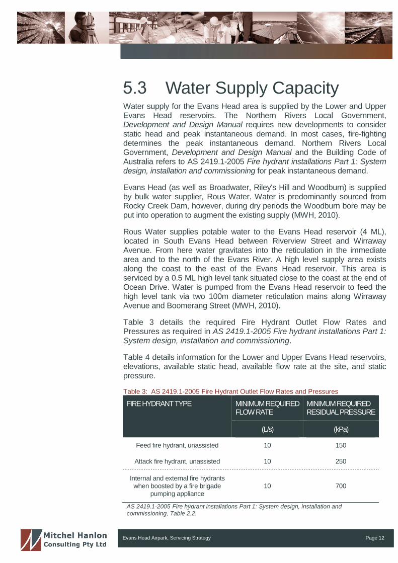
Water Supply CapacityWater supply for the Evans Head area is supplied by the Lower and UpperEvans Head reservoirs. The Northern Rivers Local Government,Development and Design Manual requires new developments to considerstatic head and peak instantaneous demand. In most cases, fire-fightingdetermines the peak instantaneous demand. Northern Rivers LocalGovernment, Development and Design Manual and the Building Code ofAustralia refers to AS 2419.1-2005 Fire hydrant installations Part 1: Systemdesign, installation and commissioning for peak instantaneous demand.
Evans Head (as well as Broadwater, Riley's Hill and Woodburn) is suppliedby bulk water supplier, Rous Water. Water is predominantly sourced fromRocky Creek Dam, however, during dry periods the Woodburn bore may beput into operation to augment the existing supply (MWH, 2010).
Rous Water supplies potable water to the Evans Head reservoir (4 ML),located in South Evans Head between Riverview Street and WirrawayAvenue. From here water gravitates into the reticulation in the immediatearea and to the north of the Evans River. A high level supply area existsalong the coast to the east of the Evans Head reservoir. This area isserviced by a 0.5 ML high level tank situated close to the coast at the end ofOcean Drive. Water is pumped from the Evans Head reservoir to feed thehigh level tank via two 100m diameter reticulation mains along WirrawayAvenue and Boomerang Street (MWH, 2010).
Table 3 details the required Fire Hydrant Outlet Flow Rates andPressures as required in AS 2419.1-2005 Fire hydrant installations Part 1:System design, installation and commissioning.
Table 4 details information for the Lower and Upper Evans Head reservoirs,elevations, available static head, available flow rate at the site, and staticpressure.
Table 3: AS 2419.1-2005 Fire Hydrant Outlet Flow Rates and Pressures
FIREHYDRANTTYPE MINIMUMREQUIREDFLOWRATE
MINIMUMREQUIREDRESIDUALPRESSURE
(L/s) (kPa)
Feed fire hydrant, unassisted 10 150
Attack fire hydrant, unassisted 10 250
Internal and external fire hydrantswhen boosted by a fire brigade
pumping appliance10 700
AS 2419.1-2005 Fire hydrant installations Part 1: System design, installation andcommissioning, Table 2.2.
Evans Head Airpark, Servicing Strategy Page 13
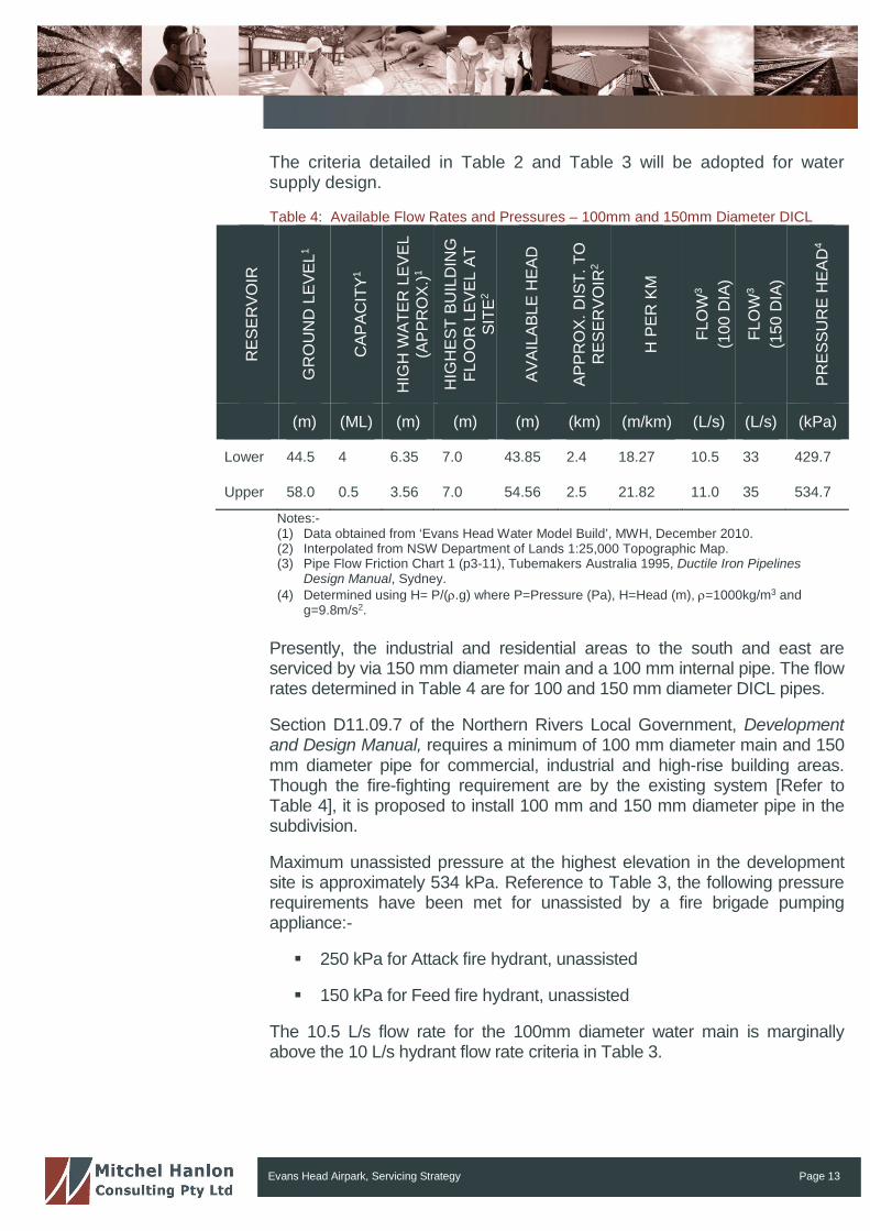
The criteria detailed in Table 2 and Table 3 will be adopted for watersupply design.
Table 4: Available Flow Rates and Pressures – 100mm and 150mm Diameter DICL
RE
SE
RV
OIR
GR
OU
ND
LE
VE
L1
CA
PA
CIT
Y1
HIG
HW
AT
ER
LE
VE
L(A
PP
RO
X.)
1
HIG
HE
ST
BU
ILD
ING
FLO
OR
LE
VE
LA
TS
ITE
2
AV
AIL
AB
LE
HE
AD
AP
PR
OX
.D
IST
.T
OR
ES
ER
VO
IR2
HP
ER
KM
FLO
W3
(100
DIA
)
FLO
W3
(150
DIA
)
PR
ES
SU
RE
HE
AD
4
(m) (ML) (m) (m) (m) (km) (m/km) (L/s) (L/s) (kPa)
Lower 44.5 4 6.35 7.0 43.85 2.4 18.27 10.5 33 429.7
Upper 58.0 0.5 3.56 7.0 54.56 2.5 21.82 11.0 35 534.7
Notes:-(1) Data obtained from ‘Evans Head Water Model Build’, MWH, December 2010.(2) Interpolated from NSW Department of Lands 1:25,000 Topographic Map.(3) Pipe Flow Friction Chart 1 (p3-11), Tubemakers Australia 1995, Ductile Iron Pipelines
Design Manual, Sydney.(4) Determined using H= P/(.g) where P=Pressure (Pa), H=Head (m), =1000kg/m3 and
g=9.8m/s2.
Presently, the industrial and residential areas to the south and east areserviced by via 150 mm diameter main and a 100 mm internal pipe. The flowrates determined in Table 4 are for 100 and 150 mm diameter DICL pipes.
Section D11.09.7 of the Northern Rivers Local Government, Developmentand Design Manual, requires a minimum of 100 mm diameter main and 150mm diameter pipe for commercial, industrial and high-rise building areas.Though the fire-fighting requirement are by the existing system [Refer toTable 4], it is proposed to install 100 mm and 150 mm diameter pipe in thesubdivision.
Maximum unassisted pressure at the highest elevation in the developmentsite is approximately 534 kPa. Reference to Table 3, the following pressurerequirements have been met for unassisted by a fire brigade pumpingappliance:-
250 kPa for Attack fire hydrant, unassisted
150 kPa for Feed fire hydrant, unassisted
The 10.5 L/s flow rate for the 100mm diameter water main is marginallyabove the 10 L/s hydrant flow rate criteria in Table 3.
Evans Head Airpark, Servicing Strategy Page 14
Concept Internal WaterSupply
The internal water supply will have the following characteristics:-
The eastern residential, industrial and medium density precinct areaswill be serviced via the extension of the existing 150 mm diameterwater supply main located within Memorial Airport Drive. The new 150mm diameter main will be installed in the footpath of the proposednew road running from Memorial Airport Drive to Currajong Street.The new 150 mm main will connect to the existing 100 mm diameterwater supply main in Currajong Street.
A new 100 mm diameter main will be installed throughout theresidential area (including the proposed future hotel / motel) andconnect back on to the proposed 150 mm main. This will ensurehydraulic connectivity thereby reducing the incidence of air pockets inthe line;
The western museum precinct will be serviced via a new 150 mmdiameter connection to the 200 mm diameter water main located onthe northern side of Woodburn-Evan Heads Road. The new 150 mmmain will be installed in the footpath of the proposed roads andextended throughout the residential / museum area and reconnect tothe existing 200 mm diameter water supply main in Woodburn-EvanHeads Road. Negotiations will be held with Rous Water following theissue of development consent;
The exact location and depth of the water mains will need to beconfirmed prior to formalising the proposed connection points above;
The main will provide water supply to each of the residential lots viawater standard water service connections. Each connection will bemetered and have a non-return valve to prevent backflowcontamination;
External fire hydrants will be installed in the water main at 70 metreintervals. Hydrants will also be installed at high and low points in theline;
Stop valves will be installed in the water main to permit maintenance;and
Services to be 20mm diameter.
It is should be noted that the above mentioned provisions are concept onlyand are subject to significant change as a result of the design phase.
Evans Head Airpark, Servicing Strategy Page 15
Sewer
IntroductionThe following sections details specific requirements and the capacity of theexisting system to receive sewage from the site. It also details the proposedsewerage infrastructure.
Existing Sewerage SupplySystem
Richmond Valley Council’s GIS indicates the following sewerageinfrastructure:-
A 300 mm diameter rising sewer (pressure) main traverses middle ofthe site. The main runs from Woodburn-Evans Head Road to theEvans Head Wastewater Treatment Facility (WWTF) adjoining thesite to the north;
The industrial estate immediately to the south of the site is servicedvia a 150 mm diameter gravity main which discharges at a seweragepump station located along Currajong Street. Sewerage is thenconveyed via a 300 mm diameter rising sewer main which connectsto the rising main traversing the site and then discharges at theWWTF located to the north;
The pump station situated along Currajong Street is identified asEvans Head No. 8 WWPS (SPS 308) and receives flows from thelocal gravity catchment to the north west of Evans Head.
Sewerage generated within the nearby residential land to the southand east of the site is conveyed to a pump station located adjacent toPine Lane (SPS 304). Sewerage is then pumped via a 200 mmdiameter rising main situated in the western portion of theBroadwater-Evans Head Road / Flame Street road reserve to theWWTF located to the north.
The 300mm diameter rising sewer main that traverses the sitedischarges sewage from a major part of the Evans Head area; and
The exact location and depth of the sewer mains will need to beconfirmed prior to formalising the proposed connection points above.

Evans Head Airpark, Servicing Strategy Page 16
Projected EquivalentTenements and SewageFlows
The projected Equivalent Tenements (ET’s) for the proposed development inrelation to sewerage has been calculated in accordance with the ‘AUS-SPEC#1 Development and Design Manual’.
Section D12.06 states that initial design may assume that one EquivalentTenement (ET), which equates to a standard single dwelling unit, is equal to3.2 equivalent persons (EP), i.e. 1 ET = 3.2 EP.
Based upon the relevant design loading criteria, the number of ETs for thedevelopment are detailed in Table 5.
Evans Head Airpark, Servicing Strategy Page 17
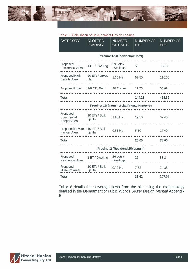
Table 5: Calculation of Development Design Loading
CATEGORY ADOPTEDLOADING
NUMBEROF UNITS
NUMBER OFETs
NUMBER OFEPs
Precinct 1A (Residential/Hotel)
ProposedResidential Area
1 ET / Dwelling59 Lots /Dwellings
59 188.8
Proposed HighDensity Area
50 ETs / GrossHa
1.35 Ha 67.50 216.00
Proposed Hotel 1/8 ET / Bed 90 Rooms 17.78 56.89
Total 144.28 461.69
Precinct 1B (Commercial/Private Hangers)
ProposedCommercialHanger Area
10 ETs / Builtup Ha
1.95 Ha 19.50 62.40
Proposed PrivateHanger Area
10 ETs / Builtup Ha
0.55 Ha 5.50 17.60
Total 25.00 78.00
Precinct 2 (Residential/Museum)
ProposedResidential Area
1 ET / Dwelling 26 Lots /Dwellings
26 83.2
ProposedMuseum Area
10 ETs / Builtup Ha
0.72 Ha 7.62 24.38
Total 33.62 107.58
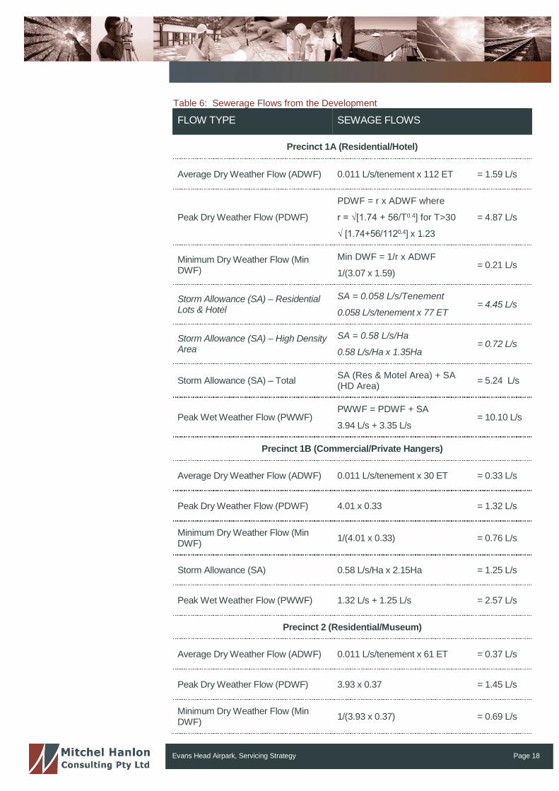
Table 6 details the sewerage flows from the site using the methodologydetailed in the Department of Public Work’s Sewer Design Manual AppendixB.
Evans Head Airpark, Servicing Strategy Page 18
Table 6: Sewerage Flows from the Development
FLOW TYPE SEWAGE FLOWS
Precinct 1A (Residential/Hotel)
Average Dry Weather Flow (ADWF) 0.011 L/s/tenement x 112 ET = 1.59 L/s
Peak Dry Weather Flow (PDWF)
PDWF = r x ADWF where
r = √[1.74 + 56/T0.4] for T>30
√ [1.74+56/1120.4] x 1.23
= 4.87 L/s
Minimum Dry Weather Flow (MinDWF)
Min DWF = 1/r x ADWF
1/(3.07 x 1.59)= 0.21 L/s
Storm Allowance (SA) – ResidentialLots & Hotel
SA = 0.058 L/s/Tenement
0.058 L/s/tenement x 77 ET= 4.45 L/s
Storm Allowance (SA) – High DensityArea
SA = 0.58 L/s/Ha
0.58 L/s/Ha x 1.35Ha= 0.72 L/s
Storm Allowance (SA) – TotalSA (Res & Motel Area) + SA(HD Area)
= 5.24 L/s
Peak Wet Weather Flow (PWWF)PWWF = PDWF + SA
3.94 L/s + 3.35 L/s= 10.10 L/s
Precinct 1B (Commercial/Private Hangers)
Average Dry Weather Flow (ADWF) 0.011 L/s/tenement x 30 ET = 0.33 L/s
Peak Dry Weather Flow (PDWF) 4.01 x 0.33 = 1.32 L/s
Minimum Dry Weather Flow (MinDWF)
1/(4.01 x 0.33) = 0.76 L/s
Storm Allowance (SA) 0.58 L/s/Ha x 2.15Ha = 1.25 L/s
Peak Wet Weather Flow (PWWF) 1.32 L/s + 1.25 L/s = 2.57 L/s
Precinct 2 (Residential/Museum)
Average Dry Weather Flow (ADWF) 0.011 L/s/tenement x 61 ET = 0.37 L/s
Peak Dry Weather Flow (PDWF) 3.93 x 0.37 = 1.45 L/s
Minimum Dry Weather Flow (MinDWF)
1/(3.93 x 0.37) = 0.69 L/s

Evans Head Airpark, Servicing Strategy Page 19
FLOW TYPE SEWAGE FLOWS
Storm Allowance (SA) – ResidentialLots
SA = 0.058 L/s/Tenement
0.058 L/s/tenement x 34 ET= 1.51 L/s
Storm Allowance (SA) – MuseumArea
SA = 0.58 L/s/Ha
0.58 L/s/Ha x 0.75 Ha= 0.44 L/s
Storm Allowance (SA) – Total SA (Res) + SA (Museum Area) = 1.95 L/s
Peak Wet Weather Flow (PWWF) 1.45 L/s + 1.94 L/s = 3.40 L/s
NOTE: The number of ETs calculated for Precinct 3 = 25, however, 30 ETs have been assumed to allow flowcalculations to be undertaken.
Evans Head Airpark, Servicing Strategy Page 20
Concept SewerageReticulation
The proposed sewerage system for the development will be assessed inaccordance with the Northern Rivers Local Government, Development andDesign Manual and the NSW Department of Public Works Department’sManual of Practice: Sewer Design.
It is proposed to sewer the development via the following:
Where possible all lots within Precinct 1A and 1B will be serviced vianew gravity sewer mains, these mains will transfer sewage to acentralised pump station located to the south of the site (EHPS08).This pump station discharges to the existing 300mm rising mainwhich traverses the site.
Should the servicing of these areas not be possible (due to minimumgrade restrictions etc), the areas will be serviced via a combination ofgravity and pressure sewer systems;
It is understood that due to recent development within the area theexisting pressurised sewer main that traverses the site (north tosouth) is expected to be at capacity.
As such, it is proposed to construct a new suitably sized pump stationlocated towards the center of the site. A new suitably sized risingmain will also be constructed to convey sewage to the sewagetreatment plant to the north of the site;
It is proposed to relocate the length of rising main fronting proposedlots 14 – 23;
Lots 14 – 23 (industrial hanger lots) will be serviced via new gravitysewer mains, these mains will transfer sewage to a grinder pumpstation (or similar) which will feed to the proposed pump station;
All lots within Precinct 2 will be serviced via new gravity sewer mains,these mains will transfer sewage to the new pump station which willfeed to the proposed the rising main.
It is should be noted that the above mentioned provisions are concept onlyand are subject to significant change as a result of the design phase.
Evans Head Airpark, Servicing Strategy Page 21
The following specifications will be utilised and maintained to ensureconstruction materials and methods meet the requirements of NRLGDevelopment and Design Manual:
Gravity main pipe material is to be modified Polyvinyl Chloride(mPVC) or un-plasticised Polyvinyl Chloride (uPVC). If mPVC is used,metal detectable tracer tape is to be placed in the trench above thepipe prior to backfill. uPVC pipes for gravity sewers shall be RRJclass SN8 in 3m length;
Gravity pipelines for road crossings or where located under roadpavements shall be series 1 white uPVC pressure pipe min class 12,or DI Epoxy Lined internally;
Rising mains are to be un-plasticised Polyvinyl Chloride (uPVC) orDuctile Iron Concrete Lined (DICL);
Gravity mains will have a minimum pipe size of 150 mm diameter.Class to be determined based on final depth of installation;
Rising mains will have a minimum pipe size of 100 mm diameter.Class to be determined based on final depth of installation;
Minimum pipe cover in footpaths, table drains and driveways is 450mm and 750 mm in road carriageways; and
As the development is a community title development Evans HeadAirpark Pty Ltd (or their successors) will have maintenance andcontrol of the reticulation system.
Evans Head Airpark, Servicing Strategy Page 22
Stormwater QualityPart G Subdivision of the Richmond Valley Council’s DCP requiresstormwater drainage to be designed in accordance with Council’sspecifications with drainage to be directed to Council drainage infrastructure.In addition, drainage is to reflect the pre-existing or natural situation in termsof location, quantity, quality and velocity. Moreover, the principles of watersensitive urban design (WSUD) should be employed especially for largesubdivisions.
As such, the objectives of Part I9 Water Sensitive Urban Design of the DCPwill be referred to, to ensure that adequate water quality managementprinciples are incorporated into development design and this is carriedthrough into the construction phase.
For this development the airpark is located in a flat area, an ideal location foran aerodrome. As a consequence, there is minimal fall across the site.Currently drainage from the existing runways is directed to heritage-listedexisting open-drainage pits and piped to the discharge point located atexisting open channels.
Stormwater from the proposed allotments will be partially captured by on-siterainwater tanks. Dwellings harvest rainwater and potentially re-use thatrainwater for toilet flushing and gardens and in some cases laundry. Inaddition to the obvious resource efficiency outcome the rainwater tanks alsomitigate the effect of urbanisation on the flow regime of the waterways. Byreducing the peak flows the aquatic ecosystems within the waterways arebetter conserved.
Due to the flat nature of the site, runoff discharged from the lots, accessroads and taxiways will flow via overland flow paths to the existing channelsand waterways. These flow-paths will consist of road kerb and gutters, swaledrains and table drains. Some site regrading will be required to ensure flowefficacy. The regrading will consist of cut-and-fill to achieve maximum falls of0.3 to 0.5%. As a result, changes in elevation are expected to be minimal.
Water quality will be controlled via gross-pollutant traps and bio-retentionunits located within the drains and at the point of discharge to the existingwaterways. The bio-retention units will be designed to work in conjunctionwith a traditional kerb and guttering approach preferred by residents. Thebio-retention units will be positioned on the border of the riparian reservetreating stormwater before it enters the waterway.
The riparian areas will be maintained and managed as functioningwaterways in an urban context. The intent is for the waterways to be to be afeature of the subdivision. A riparian buffer will be maintained to ensure thesustainability of the aquatic ecosystems. Walkways will be incorporated intothe design to allow public access.
Evans Head Airpark, Servicing Strategy Page 23
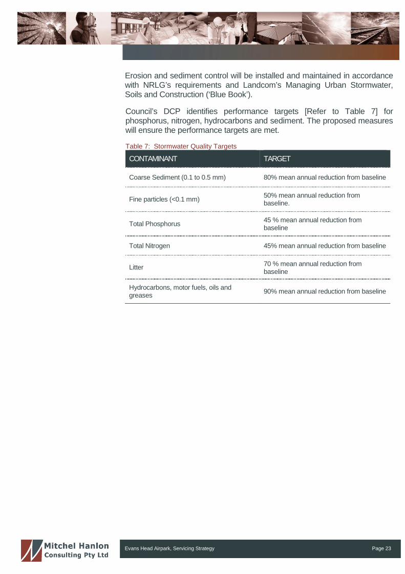
Erosion and sediment control will be installed and maintained in accordancewith NRLG’s requirements and Landcom’s Managing Urban Stormwater,Soils and Construction (‘Blue Book’).
Council’s DCP identifies performance targets [Refer to Table 7] forphosphorus, nitrogen, hydrocarbons and sediment. The proposed measureswill ensure the performance targets are met.
Table 7: Stormwater Quality Targets
CONTAMINANT TARGET
Coarse Sediment (0.1 to 0.5 mm) 80% mean annual reduction from baseline
Fine particles (<0.1 mm)50% mean annual reduction frombaseline.
Total Phosphorus45 % mean annual reduction frombaseline
Total Nitrogen 45% mean annual reduction from baseline
Litter70 % mean annual reduction frombaseline
Hydrocarbons, motor fuels, oils andgreases
90% mean annual reduction from baseline
Evans Head Airpark, Servicing Strategy Page 24
ReferencesAS 2419.1-2005 Fire hydrant installations Part 1: System design, installationand commissioning.
GHD 2010, Richmond Valley Council, Review of Evans Head SewerageAugmentation Strategy, May 2010 Rev. 3
MWH 2010, Evans Head Water Model Build, December 2010
NSW Department of Public Works 1987, Manual of Practice: Sewer Design.
Northern Rivers Local Government, Development and Design Manual.
Pilgrim, D. (Ed.) 2001, Australian Rainfall and Runoff – Volume 1, Institutionof Engineers Australia, ISBN 0 85825 744 0.
Richmond Valley Council GIS
Richmond Valley Development Control Plan 2012.
Tubemakers Australia 1995, Ductile Iron Pipelines Design Manual, Sydney.