“1kuns-pf: kenyan university nanosatellite-precursor · by using the ground station located in...
TRANSCRIPT

1KUNS
1st Kenyan University
NanoSatellite
Date: 31 March 2016
1 of 39
Proposal in the framework of:
United Nations/Japan Cooperation Programme on
CubeSat Deployment from the International Space Station (ISS)
Japanese Experiment Module (Kibo), “KiboCUBE”
“1KUNS-PF:
1st Kenyan University NanoSatellite-Precursor
Flight”
Authors
Prof. J. Mwangi Mbuthia and Prof. Heywood Ouma
Department of Electrical and Information Engineering.
Address Universityof Nairobi, Harry Thuku Road, P. O. Box 30197, Nairobi
Tel. +254 20 3318262/5 Ext. 28400
Cell +254 706230668
e-mail: [email protected]

1KUNS
1st Kenyan University
NanoSatellite
Date: 31 March 2016
2 of 39
Table of Contents
“1KUNS-PF: 1st KenyanUniversity NanoSatellite Precursor Flight” .....................................................................1
1 1KUNS – PF ......................................................................................................................................................3
2 General Information ........................................................................................................................................4
2.1 Name of the 1U CubeSat ............................................................................................................................ 4
2.2 Name of the organization ........................................................................................................................... 4
2.3 Name of the head of the organization ........................................................................................................ 4
2.4 Name of the Principal Investigator (this will be the point of contact) ....................................................... 4
2.5 Team/Research collaborators, implementation structure and schedule ..................................................... 4
2.6 CubeSat mission and success criteria ......................................................................................................... 8
2.7 Desired launchand deployment date of the CubeSat .................................................................................. 8
3 Detailed information ........................................................................................................................................9
3.1 Specification of the Cubesat ....................................................................................................................... 9
3.2 Technical features of the Cubesat ............................................................................................................ 25
3.3 Plans for manufacturing the Cubesat ....................................................................................................... 30
3.4 Test plan for the CubeSat with facilities to be used ................................................................................. 32
3.5 Financial Plan ........................................................................................................................................... 38
3.6 Ground operation plan, including a maintenance plan for the ground station ......................................... 38
3.7 Plan for frequency license ........................................................................................................................ 38
3.8 Outreach/Capacity-building ..................................................................................................................... 39
3.9 Supplementary notes ................................................................................................................................ 39
3.10 References ................................................................................................................................................ 39

1KUNS
1st Kenyan University
NanoSatellite
Date: 31 March 2016
3 of 39
1 1KUNS – PF
The scope of this document is to submit the proposal for the 1U Cubesat named 1KUNS-PF (1st Kenyan
University Nano-Satellite – Precursor Flight) in response to the Announcement of Opportunities in the
framework of the United Nations/Japan Cooperation Programme on CubeSat Deployment from the International
Space Station (ISS) Japanese Experiment Module (Kibo) “KiboCUBE”.
The mission develops in a partnership between the School of Engineering - University of Nairobi, Kenya and
University of Rome “La Sapienza”, Rome, Italy, with the support of the National Space Secretariat of Kenya
andsponsorship from the Italian Space Agency, in the framework of the ASI-Sapienza Agreement for the
management of the scientific activity at the Broglio Space Center in Malindi, Kenya.
This project is part of the results of an international cooperation, in the framework of the “renewal of San Marco
Agreement, between Kenya and Italy”, as said by Dr. John N. Kimani, Lead Scientist, National Space
Secretariat, during the opening of the Second ASI-Sapienza Meeting with Kenyan Universities, hosted by the
School of Engineering, University of Nairobi, on Tuesday 26th January, 2016.

1KUNS
1st Kenyan University
NanoSatellite
Date: 31 March 2016
4 of 39
2 General Information
2.1 Name of the 1U CubeSat
1KUNS-PF: 1st Kenyan University Nano Satellite Precursor Flight
2.2 Name of the organization
University of Nairobi
2.3 Name of the head of the organization
Prof. Peter M. F. Mbithi - Vice Chancellor
2.4 Name of the Principal Investigator (this will be the point of contact)
Prof. J. Mwangi Mbuthia, University of Nairobi email [email protected] Cell
+254706230668
2.5 Team/Research collaborators, implementation structure and schedule
The team of University of Nairobi will be composed by:
Prof. J. Mwangi Mbuthia – IKUNS Cube Sattellite - Kenyan Payload and Power Electronics–Postgraduate
Course Coordinator
Prof. Heywood Ouma–IKUNS Cube Satellite Electronics and Postgraduate Course Lecturer
Prof. Vitalice Oduol – IKUNS Cube Satellite Antennas and Communicationand Postgraduate Course
Lecturer
Dr W. Njoroge Mwema – IKUNS Cube Satellite Operation and Postgraduate Course Lecturer
Undergraduate Students Selected to participate in Building the Cubesat
MWANIKI A NGARI M
NJUNG'E ANTHONY NDUNG'U M
MBUGUA KEVIN THAIRU M
MURIUKI EDDY KIMATHI M
KIPRONO NGETICH VICTOR M
1KUNS
1st Kenyan University
NanoSatellite
Date: 31 March 2016
5 of 39
OCHIENG BONIFACE M
INGARI PAUL NGANYI M
LONGORIO PAUL M
WASWA WEKESA CALEB M
KIPTOON KIPKURUI DANIEL M
MULONGO JOHN PAUL M
NYAKINYUA DAVID MWANGI M
SUPEYO M MOSES M
BOMETT NIGEL KIMUTAI M
ESSAJEE MOHAMMED MUSTAFA M
PAUL JAPHETH MWONGELA M
NYABUTO WREFORD MOMANYI M
JUMA TERESA KHAKASA F
APIYO ANTONIO SHEM M
NDIWA HILLARY CHESEBE M
MUSYOKI NANCY WANDIA F
MARARIA CECILIA WANJIRU F
GITUNDU MONICA WANJIRU F
M.Sc. Students Selected to participate in Building the Cubesat
NJERI CASTY GAKII F
KAMORE DAVID MAINA M
NG'ANG'A FIDEL MACHARIA M
KERRE MOSES SIMIYU M
WACHIRA CHARLES MUCHIRI M
LUTI THOMAS WAMBUA M
NJOROGE KENNEDY NJOROGE M
NANGO BENTLAY ODHIAMBO M
KABUTHA SAMUEL GACHIHI M
MUTUA RODGERS MUTHI M
The whole program is realized in collaboration with University of Rome “La Sapienza” in the framework of the
IKUNS ASI-Sapienza program. The1KUNS-PF satellite team will have at disposal the facilities of University of
Rome, including S5Lab (Sapienza Space Systems and Space Surveillance Laboratory) and SaSLab.
In this framework, the University of Rome will provide support in terms of contribution to design and
development, test and integration facilities and manpower through students, PhD and researchers that will be
involved in 1KUNS-PF project, fostering direct cooperation among Italian and Kenyan students.
The training and educational benefits will be enhanced by the 1KUNS Precursor program.
Moreover, a sharing of human resources and facilities is expected; for instance, the IKUNS Ground Station,
which is going to be installed at Broglio Space Centre, will be used for the 1KUNS-PF program.
1KUNS
1st Kenyan University
NanoSatellite
Date: 31 March 2016
6 of 39
In addition, an International Postgraduate Course in “Space Mission Design and Management” was established,
jointly by University of Nairobi and University of Rome La Sapienza. The students enrolled in this Postgraduate
Course will be required to gain at least 30% of the credits in the partner University, meaning that Kenyan
students will attend courses at University of Rome La Sapienza and Italian students will attend courses at
University Nairobi. Funding for the Postgraduate Course will be provided by ASI and European Companies.
Students enrolled in the Postgraduate Course will participate in the 1Kuns-PF nanosatellite design, realization
and operation on orbit as part of their curricular activity.
The team in charge of 1KUNS –PF on the University of Rome side includes
Prof. Mario Marchetti ASI/Sapienza Agreement Coordinator
Prof. Fabio Santoni – Director of the Postgraduate Course in “Space Mission Design and Management”
Prof. Fabrizio Piergentili – Scientific Responsible of IKUNS project
Dr Lorenzo Arena – Ursa Maior cubesat technical responsible
Dr Tommaso Cardona – Ground segment
Dr Gioacchino Scire – Payload integration
Dr Andrea Delfini – Ground testing
Mr Armando Grossi – Attitude Determination and Control
Mr Livio Agostini – Optical Payload
Mrs LuanaCalisti – Virtual modeling and design
Mr Michele Gaeta – Telecommunication
Mr Vito LaMarca – OBDH and Telemetry
Mr Luca Maioli – Satellite System and Attitude Determination and Control
Mrs EleonoraMarotta – Power and Photovoltaic system
At present, the University of Nairobi is developing the IKUNS 6U cubesat together with University of Rome “La
Sapienza” and thanks to this activity it is achieving hands-on experience in cubesat manufacturing and operation,
by using the ground station located in the Broglio Space Center in Malindi (Kenya).
The IKUNS 6U is under development, hence design, prototypes and some flight hardware are already available
in house. Some parts of the design and hardware parts will be used for 1KUNS-PF, facilitating the design and
AIT (assembly/integration/testing) process andguaranteeing a timely execution of the activities, according to the
flight-readiness requirements of “KiboCube” Announcement of Opportunities.
The University of Nairobi will be in charge of the project. University of Rome will provide technical support and
organizational supervision, whenever required, in all the program phases.
The Italian Space Agency will support the 1KUNS-PF programas part of the already active program IKUNS,
through specific additional financial support to the IKUNS project.
The Collaboration between Kenyan and Italian scientific Institutions in building University satellites has a very
long history, dating back to the sixties by establishing the San Marco program in Malindi and by the launches of
San Marco satellites. Since those times, the collaboration between the two countries in space activity has
1KUNS
1st Kenyan University
NanoSatellite
Date: 31 March 2016
7 of 39
increased. At the moment, the microsatellite IKUNS, founded by the Italian Space Agency, is under
development thanks to an agreement between University of Rome “La Sapienza” and University of Nairobi.
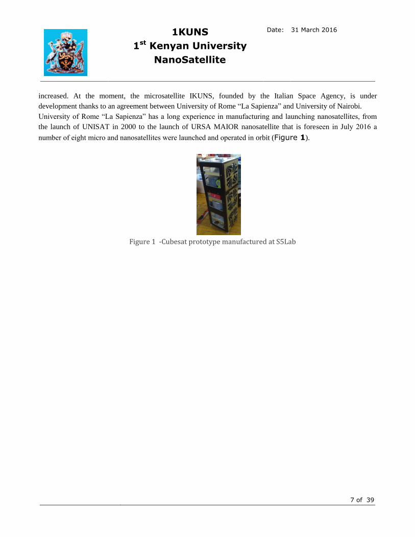
University of Rome “La Sapienza” has a long experience in manufacturing and launching nanosatellites, from
the launch of UNISAT in 2000 to the launch of URSA MAIOR nanosatellite that is foreseen in July 2016 a
number of eight micro and nanosatellites were launched and operated in orbit (Figure 1).
Figure 1 -Cubesat prototype manufactured at S5Lab

1KUNS
1st Kenyan University
NanoSatellite
Date: 31 March 2016
8 of 39
2.6 CubeSat mission and success criteria
The 1KUNS-PFmissionis a technology demonstration, aiming at testing in orbit in-house developed technology,
in collaboration between University of Nairobi, Kenya and University of Rome La Sapienza, Italy, to test in
relevant space environment several critical technologies, needed for the IKUNS program, a 6U University
Cubesat for Earth observation in the visual band, funded by ASI and currently under development. The aim
ofIKUNS-PFis testingin orbit and prove functionality of several components, either commercial or developed in
house, intended for use in the IKUNS mission. In detail, the in-house developed systems are:
- Silicon cell solar panel
- Telemetry Electronic Board
- 3-DOF attitude control system, using a momentum wheel
Hence, the primary mission goal mission is to verify the performance of the on-board subsystems, by
receivingtelemetry data from the satellite. Achieving this goal will represent a minimum mission success.
Moreover, secondary scientific objectives are associated with the acquisition, store on-board, and correctly
transmit to ground of low-definition, panchromatic images of the East Africa region, where the interest of Kenya
lies for the Earth Observation applications in terms of agriculture monitoring, coastal areas monitoring, etc. The
1KUNS-PF mission will allow to test and verify the performances obtained with the selected devices and
developed software, in order to support the development of the IKUNS program.
2.7 Desired launch and deployment date of the CubeSat
A development time of 12 months, starting from the notification of acceptance of the present proposal, is
foreseen for the development and delivery of the satellite, including design, manufacturing and testing.
Moreover, a schedule shortening (up to 3 months) can be implemented, in case of need for a matching with the
ISS planning of activities, to be negotiated at the moment of the entering into the Contract with JAXA.
The launch of 1KUNS-PF should be within next 18/24 months, in order to exploit its achievements in the
framework of the IKUNS project. No specific constraint in the launch date is imposed by the mission objectives.
1KUNS-PFprogramme schedule, described in details in the Sec. 3.3, will be compliant with KiboCube schedule
and related milestones, as reported in the related “Announcement of Opportunity”.

1KUNS
1st Kenyan University
NanoSatellite
Date: 31 March 2016
9 of 39
3 Detailed information
3.1 Specification of the Cubesat
In the following sections, a general description of the Cubesat system architecture and subsystem components is
stated. The detailed and final design, to be defined in the first phase of the program, will be compliant with
technical requirements reported in the document “JEM Payload Accommodation Handbook -Vol. 8- Small
Satellite Deployment Interface Control Document (JX-ESPC-101133)”. The Verification Matrix, contained in
Appendix C of the “Handbook”, will be used to state the compliance to the set of requirements.
The technical and scientific mission goals are reported in Sec. 2.6. Additionally, the “1KUNS-PF” will be
exploited in the frame of the IKUNS ASI program, where the educational aspects, towards capacity building in
space mission design, management and satellite components manufacturing, are very relevant. The mission is
intended to fit within University student courses, or Postgraduate Courses, which brings about fast development
in a very strict timeline.
Therefore, two main design drivers are followed:
(i) simplicity of the on-board system, guaranteeing basic and well proven functionality;
(ii) choice of on-board components based on “commercial off the shelf” (COTS) technology and Cubesat
specific hardware ready on the market, with no custom developments.
The top level system requirements can be summarized as:
- Standard 1U CubeSat satellite, compatible with all dispenser and in particular with KiboCube
- Nominal mass < 1.2 kg
- Perform experimental activity in on-board power system and attitude control system
- Optical Payload in visual band to get panchromatic images of the Earth
- Ground Stations: (i) Broglio Space Center (Malindi, Kenya); (ii) Sapienza University (Rome, Italy)
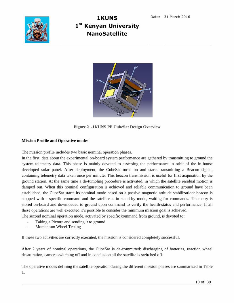
An overview of the CubeSat design is illustrated in Figure 2.
The satellite is designed to fit in every standard CubeSat dispenser (100x100x114 mm) and with an overall mass
of about 1 kg.
The on-board systems include commercial devices and in-house developed experimental devices to be tested in
orbit. These include: (i) a solar panel manufactured at University of Nairobi; (ii) a momentum wheel developed
in cooperation between University of Nairobi and Sapienza; (iii) a control/telemetry system designed to manage
the experimental devices; (iv) a commercial-off-the-shelf micro-camera.
1KUNS
1st Kenyan University
NanoSatellite
Date: 31 March 2016
10 of 39
Figure 2 -1KUNS PF CubeSat Design Overview
Mission Profile and Operative modes
The mission profile includes two basic nominal operation phases.
In the first, data about the experimental on-board system performance are gathered by transmitting to ground the
system telemetry data. This phase is mainly devoted to assessing the performance in orbit of the in-house
developed solar panel. After deployment, the CubeSat turns on and starts transmitting a Beacon signal,
containing telemetry data taken once per minute. This beacon transmission is useful for first acquisition by the
ground station. At the same time a de-tumbling procedure is activated, in which the satellite residual motion is
damped out. When this nominal configuration is achieved and reliable communication to ground have been
established, the CubeSat starts its nominal mode based on a passive magnetic attitude stabilization: beacon is
stopped with a specific command and the satellite is in stand-by mode, waiting for commands. Telemetry is
stored on-board and downloaded to ground upon command to verify the health-status and performance. If all
these operations are well executed it’s possible to consider the minimum mission goal is achieved.
The second nominal operation mode, activated by specific command from ground, is devoted to:
- Taking a Picture and sending it to ground
- Momentum Wheel Testing
If these two activities are correctly executed, the mission is considered completely successful.
After 2 years of nominal operations, the CubeSat is de-committed: discharging of batteries, reaction wheel
desaturation, camera switching off and in conclusion all the satellite is switched off.
The operative modes defining the satellite operation during the different mission phases are summarized in Table
1.

1KUNS
1st Kenyan University
NanoSatellite
Date: 31 March 2016
11 of 39
The satellite enters in safe mode when anomalies are detected and every time the battery voltage goes below a
critical threshold. Schematic diagram of operational modes and transitions is shown in Figure 3.
Table 1 – IKUNS-PF operative modes
Mode Description
Commissioning
After the deployment, 1KUNS-PF sends Beacon Signal once per minute, until
reliable communication with the ground stations is established. The desired
attitude is achieved using a passive magnetic stabilization system.
Nominal
In the first phase, telemetry is stored on-board and downloaded to ground on a
regularlybasis, to assess the performance of the on-board systems and of the
experimental solar panel developed at University of Nairobi in particular.
In the second phase, the Camera is switched on/off upon command sending
panchromatic pictures of the Earth to ground. Experiments on the momentum
wheel functionality and performance are conducted.
De-commissioning UHF transmitter and all payloads are permanently turned off, including Camera
and momentum wheel. Batteries are fully discharged.
Safe
Non-essential subsystems, such as payloads, are turned off; only the receiver
remains active, sending a beacon signal. Satellite waits command from ground to
re-establish nominal mode of operation.
Figure 3: Operative Modes block diagram

1KUNS
1st Kenyan University
NanoSatellite
Date: 31 March 2016
12 of 39
Configuration and structure
This section illustrates the main design choices and collocation of the components.
The battery package is composed by 1 Lithium-Polymer battery and 3 Nickel-Cadmium batteries
(Figure 4). To allow at the batteries to work at the right temperature, they are placed near the Lithium
Radio.
Figure 4-Ni-Cd and Li.Po Batteries
To allow at the radio to dissipate the heat and to warm the batteries, a conductive secondary structure in
aluminum is built (Figure 5).
Figure 5 -Secondary Structures for Batteries and Lithium Radio Package
1KUNS
1st Kenyan University
NanoSatellite
Date: 31 March 2016
13 of 39
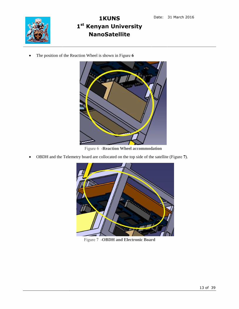
The position of the Reaction Wheel is shown in Figure 6
Figure 6 -Reaction Wheel accommodation
OBDH and the Telemetry board are collocated on the top side of the satellite (Figure 7).
Figure 7 -OBDH and Electronic Board

1KUNS
1st Kenyan University
NanoSatellite
Date: 31 March 2016
14 of 39
On top of the Telemetry board, there are the GPS receiver and magnetometers (Figure 8).
Figure 8 -GPS and Magnetometer
The selected position for the Camera is illustrated in Figure 9
Figure 9-Nano-Camera

1KUNS
1st Kenyan University
NanoSatellite
Date: 31 March 2016
15 of 39
The two omni-directional antennas are collocated on opposite sides of the satellites (Figure 10).
Figure 10 -Omni-Directional Antennas
The Permanent Magnets, used to passively stabilize the altitudeof the IKUNS-PF are colocated on the
inner corners of the CubeSat. A detail of them is shown in Figure 11.
Figure 11 -Permanent Magnets
The switches are placed along the lateral edges, on +y and -y faces (Figure 12).
Figure 12-Switch

1KUNS
1st Kenyan University
NanoSatellite
Date: 31 March 2016
16 of 39
The aluminum primary structure will be custom made in the University of Nairobi laboratories, based on
the experience gained at University of Rome.
The overall mass and volume budget is summarized in Table 2. A contingency of 20% at system level is
included, considered as conservative enough for PDR level design of a Class 2 satellite, but mainly based
on COTS components.
Table 2 – Mass and Volume budget
Subsystem Size [mm] Mass [kg]
Wheel 50 x 50 x 30 0,120
Omni Antenna 1 25 x 10 x 1 0,007
Omni Antenna 2 15 x 10 x 1 0,004
Transmitter/Receivers Omni-Antenna 62 x 32 x 8,07 0,052
Li-po Battery 48 x 42,5 x 5 0,015
3 Nickel-Cadmium Batteries 34(height) x23(diameter) 0,120
Camera 34 x 24 x 12 0,020
OBDH 96 x 90 x 10 0,070
6 Body Mounted Solar Panels 98 x 82,6 x 1,1 0,174
GPS 25 x 25 x 10 0,012
Gyroscope 36,5 x 25 x 10 0,011
Magnetometer 25 x 25 x 10 0,020
Telemetry 96 x 90 x 2 0,070
Hysteresis strips 0,15 cm3
Permanent Magnet 5(height)x5(diameter)
2 Switches 15 x 0,6 x 12 0,008
Secondary structures
0,077
Structure 100 x 100 x 114 0,130
TOTAL (with no contingency) 100 x 100 x 114 0,910
TOTAL (with 20% contingency)
1,092
Thermal control
The satellite thermal control will be completely passive. The small dimension of the CubeSat and its
partially uncontrolled attitude will assure a continuous orientation change with respect to the sun and a
homogenous heat distribution among the satellite faces. During the shadow phase of the orbit, the
transmission of a beacon signal will be used to “warm up” the satellite in case the temperature of internal
parts drops below a threshold value of approximately -10° Celsius.

1KUNS
1st Kenyan University
NanoSatellite
Date: 31 March 2016
17 of 39
Power
The components used in the power system are:
Commercial triple junction cells solar panels (5x, two cells each)
o Mass (g): 29
o Length (mm): 98
o Width (mm): 82.6
o Height (mm): 1.1
o Optimal voltage: 4.7 V - 4.8 V
o Optimal current: 490 mA - 508 mA
o Maximum power: 2.3 W
o Efficiency: 30%
o Sensor supplies: 3.3 V and 5.0 V
In-house developed silicon cell solar panel (1x)
1S 3.7V Li-Po battery
o Mass (g): 27.5
o Length (mm): 45
o Width (mm): 34
o Height (mm): 8
o Voltage (V): 3.7
o Capacity (mAh): 1500
o Capacity (Wh): 5.5

1KUNS
1st Kenyan University
NanoSatellite
Date: 31 March 2016
18 of 39
Three cells 1.2V Ni-Cd battery pack
o Mass (g): 40
o Height / Ø: 34 / 23 mm
o Voltage (V): 1.2
o Capacity (mAh): 1250
o Capacity (Wh): 1.5
In-house developed charger regulator
The power is stored in two battery packs, a Ni-Cd and a Li-Po: the first battery pack is charged by the silicon
cells panel, the second one is charged by the triple junction cells.
Power system has to ensure the needed power for all subsystem. For simplicity and reliability purpose,
deployment mechanisms are avoided and the solar panels will be body mounted. In detail, five faces are covered
with triple-junction panels, made of two cells in series. The last face is covered with a silicon solar panel,
representing a payload for IKUNS-PF.
The load power is distributed among:
On Board Computer (OBDH)
Communication System
Payload (Camera)
Telemetry
GPS receiver
As a preliminary power estimation, two possible timing transmission have been considered: in the first case
(considered as a worst-case for power budget considerations), IKUNS-PF transmits 5 minutes/orbit, while in the
second case a beacon signal is transmitted. The average power budget calculations are summarized in Table 3.
Table 3 - average power budget calculations
Power (W) % eachorbit (case A) % eachorbit (case B)
Lithium_Radio 10 1/18 1/12
OBDH 0.2 1 1
Camera 0.6 1/18 1/18
Telemetry 0.4 1/18 1/18
GPS receiver 0.12 1 1
Total average power consumption [W]
0.93 1.21
The solar panels must be able to provide sufficient power to recharge the batteries and allow to IKUNS-PF all
the operations during the periods of exposure to sunlight; the very small available surface for solar panels

1KUNS
1st Kenyan University
NanoSatellite
Date: 31 March 2016
19 of 39
strongly limits the possibility to generate power. During its motion, the Cubesat could expose to the Sun a
number of faces between 1 and 3: in the first case, the direction of Sunlight has to be normal to the one panel
surface, while in the other cases the sunlight will result tilted to all the faces. In the first case, representing the
worst case, the maximum generated power (assuming standard values for the solar cells) is 2.3W. Table 4
summarizes the total energy generation, consumption and storage during sunlight (average power consumption
of case B are used).
Table 4–Total Energy calculations
Max power generated
(single panel)
[W]
Time in the sunlight
[min]
Energy generated
per orbit
[Wh]
Energy consumption
per orbit
[Wh]
Net energy stored
per orbit
[Wh]
2.3 55 2.1 1.82 0.28
In order to supply power during the shadow phase of the orbit, a 1S Li-Po battery will be used; the position of
battery must guarantee the range of operating temperatures, therefore it will be close to the radio, that will be a
heat source. Nickel-Cadmium battery pack has more reliability, and doesn’t suffer thermal problem, so it will
provide for power source redundancy. The mission will represent a testbed for the performances of the different
batteries and drive the future design of the IKUNS 6U mission.
To reduce the complexity of the subsystem and improve the reliability, voltages of NiCd and Lipo battery pack
are chosen with similar voltages: 3 NiCd batteries in series give 4.2V approximately the same as 1 Lipo.
The charger will be based on a MPPT Controller, in order to optimize the power conversion; a switching
regulator will be configured to create a constant current or constant voltage battery charge, based on COTS
components. Telemetry data from this subsystem include temperatures and currents of arrays, batteries
temperature, current and voltage of charge, current of bus.
Table 5–Battery data
Ni-Cd Li-Po
Discharge Terminate Voltage (V) 1.00 2.80
Charge terminate Voltage (V) 1.55 4.20
NominalDischarge Voltage (V) 1.25 3.70
Operational Temperature (C) −20 to 50 −20 to 60
Sensitivity to Overcharging Medium Very high
Gravimetric Energy (Wh/kg) 40–60 130–250
Volumetric Energy (Wh/l) 50–150 150–300
GravimetricPower (W/kg) 150–200 >1000
Capacity (Ah) 1.25 3
1KUNS
1st Kenyan University
NanoSatellite
Date: 31 March 2016
20 of 39
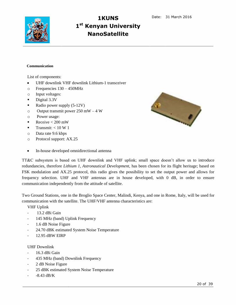
Communication
List of components:
UHF downlink VHF downlink Lithium-1 transceiver
o Frequencies 130 – 450MHz
o Input voltages:
Digital 3.3V
Radio power supply (5-12V)
o Output transmit power 250 mW – 4 W
o Power usage:
Receive < 200 mW
Transmit: < 10 W 1
o Data rate 9.6 kbps
o Protocol support: AX.25
In-house developed omnidirectional antenna
TT&C subsystem is based on UHF downlink and VHF uplink; small space doesn’t allow us to introduce
redundancies, therefore Lithium 1, Astronautical Development, has been chosen for its flight heritage; based on
FSK modulation and AX.25 protocol, this radio gives the possibility to set the output power and allows for
frequency selection. UHF and VHF antennas are in house developed, with 0 dB, in order to ensure
communication independently from the attitude of satellite.
Two Ground Stations, one in the Broglio Space Center, Malindi, Kenya, and one in Rome, Italy, will be used for
communication with the satellite. The UHF/VHF antenna characteristics are:
VHF Uplink
- 13.2 dBi Gain
- 145 MHz (band) Uplink Frequency
- 1.6 dB Noise Figure
- 24.70 dBK estimated System Noise Temperature
- 12.95 dBW EIRP
UHF Downlink
- 16.3 dBi Gain
- 435 MHz (band) Downlink Frequency
- 2 dB Noise Figure
- 25 dBK estimated System Noise Temperature
- -8.43 dB/K

1KUNS
1st Kenyan University
NanoSatellite
Date: 31 March 2016
21 of 39
Data processing
ISIS-OBC
o CPU 32-bit ARM9, 400 MHz
o 32 MB SDRAM
o 1x I2C, 1xSPI, 2xUARTs, 1x ADC, 6x PWM output, 27x GPIO
o Size 96 x 90 x 12.4 mm
o Mass 94g
On Board Data Handling is based on high heritage ISIS OBC: it manages the communication with all subsystem.
In order to reduce computational cost, a serial port (I2C or UART) will be used to communicate with external
PIC that manages power systems and payload data; other serial ports will be used to read attitude sensors and
PWM pin will control reaction wheel. OBC will communicate with Radio using UART interface.
Altitude determination and control
List of components:
MEMS 3-axis gyros
AMR 3-axis magnetometers
GPS receiver
Permanent magnet
Hysteresis dumping bars/stripes (4-8x)
The knowledge of the altitude will be provided by the combination of the solar panels data, magnetometer
measurement sand the GPS position. The latter, together with a simplified model of the Earth magnetic field, is
used to determine the local direction of the magnetic field in the inertial reference frame.The solar panels will
serve as coarse sun sensors to provide an estimate of the direction of the sun. The orientation of the CubeSatwill
then be obtained by means of a TRIAD or similar algorithm.
The altitude will be passively stabilized by a permanent magnet and permeable magnetic bars. This type of
control is based on the idea that a permanent magnet on board spacecraft in LEO align the satellite with the
Earth’s magnetic field. The altitude of a magnetically stabilized satellite is a function of the orbit and the
magnetic field lines along the orbit. In a high inclination orbit such as the ISS, a magnetically stabilized satellite
would perform two cycles per orbit. Hysteresis rods are also needed because a magnetically stabilized satellite
behaves as a second order system with very low damping factor (e.g. it oscillates around the magnetic field lines
in orbit); a magnetically “soft” material of low coercivity, easily magnetized by the Earth’s magnetic field,
follows its hysteresis patterns that make it suitable as a means for angular rate damping.
The system sizing consists in the evaluation of the permanent magnet intensity and the permeable rods volume
and arrangement on-board. These can be obtained starting from the expected environmental disturbance torque,

1KUNS
1st Kenyan University
NanoSatellite
Date: 31 March 2016
22 of 39
including aerodynamic drag, interaction between Earth’s magnetic field and residual magnetic moment of the
satellite, gravity gradient and solar radiation pressure. The latter can be ignored considering the much higher
influence of the other disturbances at the ISS operational height. The main assumptions to evaluate
environmental torques are:
300 km is considered as a reference value for the height, the lowest in the range in which the
International Space Station operates, representing a worst-case for atmospheric torque
A reference value of the atmospheric density at 300 km above the surface has been chosen using a
combination of the solar flux prediction and historical data (MSIS90), referring to 2006 atmospheric
density because it is found to be the best match with predicted solar flux. This reference value is
conservatively augmented by one order of magnitude to take into account the short term variations,
launch date changes, wrong predictions, etc. In conclusion the atmospheric density used for the system
sizing was set to 10-13
kg/m3.
A worst-case scenario in which the centre of pressure has an offset of 2 cm with respect to the centre of
mass of the Cubesat is considered.
A standard value for the satellite drag coefficient of 2.2 is used
The maximum gravity gradient torque, in which the angle between the radial axis and a satellite
principal axis is 45° is considered
For the Earth magnetic field is considered the highest value (polar magnetic field)
A residual magnetic dipole of 0.01 𝐴𝑚2is assumed.
The expected (worst case) disturbance torques are summarized in Table 6. The total Torque is calculated
considering all the disturbance torques in the same direction, which is a very conservative worst-case scenario.
Table 6–Worst case disturbance torques
Torque Value Units
Aerodynamic 1.31*10-9
Nm
GravityGradient 2.01*10-9
Nm
ResidualMagnetic Moment 5.00*10-7
Nm
TOTAL 5.04*10-7
Nm
A passive magnetic altitude control system can be designed providing a stabilization torque one order of
magnitude higher than the disturbance torque, at the maximum allowed angular deviation from the magnetic

1KUNS
1st Kenyan University
NanoSatellite
Date: 31 March 2016
23 of 39
field direction, which is set to 5 degrees. According to this empirical criterion and the data in Table 6, the desired
magnetic torque is 𝑀𝑚𝑎𝑔𝑛𝑒𝑡𝑖𝑐 = 5 ∗ 10−6𝑁𝑚).
The torque produced by a magnetic dipole is calculated as:
𝑀𝑚𝑎𝑔𝑛𝑒𝑡𝑖𝑐 = 𝑚 𝐵𝑒𝑎𝑟𝑡 ℎsin(𝛽)
where 𝑀𝑚𝑎𝑔𝑛𝑒𝑡𝑖𝑐 M is the magnetic torque, m is the permanent magnet magnetic dipole moment in Am, 𝐵𝑒𝑎𝑟𝑡 ℎ
B is the Earth’s magnetic flux density vector and 𝛽 is the angle between the two vectors. The magnetic dipole
moment is evaluated referring to the worst-case (minimum) magnetic flux density vector, that is when the
satellite is at the equator (𝐵𝑒𝑎𝑟𝑡 ℎ = 26000𝑛𝑇) and 𝛽 is 5 degrees. The resulting magnetic dipole is about 2 𝐴𝑚2.
Appropriate magnetic damping can be obtained by permeable rods. The design of this damping system is not
trivial and we refer to the literature for detailed system sizing, geometrical configuration and material selection
(see, for example: F. Santoni, M. L. Battagliere, F. Fiorillo, E. Ferrara, Optimal geometry and materials for
nanospacecraft magnetic damping systems, IEEE Transactions on Aerospace and Electronic Systems, 01/2015;
51(1):127-141; DOI:10.1109/TAES.2014.130218). A classical configuration consists of an array of
stripsarranged in the permanent magnet equatorial plane. According to the experimental results obtained in the
above mentioned reference, a system of four mumetal strips per axis provides the best performance in terms of
energy damping effectiveness per unit weight of damping material.
The altitude control system includes a in-house developed momentum wheel, as a technological demonstration
and experiment in orbit. The wheel will be activated for short periods of time using different control laws to
perform simple manoeuvres. The angular rate resulting from the activation of the wheel will be measured by the
3-axis gyroscopes and transmitted to ground to be compared with the predicted performance.
Camera module
One of the main objectives of the mission is testing a telemetry
electronic board developed in-house at University of Nairobi. This
board will be programmed to accomplish telemetry functions and
control a commercial microcamera. Under request, the board will
send the command to the camera to take a picture. The same board
will handle the image data for sending to ground, so the principal
requirement for this module is the ability to interfacing with the
board.
The main design drivers of the camera choice are the interface
protocol, the size and the programmability.
The selected camera is ArduCAM-M-2MP. it is a low cost camera with serial connection. A remarkable fact is
that the ArduCAM mini version has been used for NASA NOS3 (NASA Operational Simulator for Small

1KUNS
1st Kenyan University
NanoSatellite
Date: 31 March 2016
24 of 39
Satellite). The camera module has the 2 MP (Mega Pixels) image sensor CMOS (Complementary Metal-Oxyde
Sensor) OV2640 from Omnivision with mount for different lens. The image sensor allows to select different
image format and output (JPEG compression included). These features are important for a CubeSat mission
because the user can select the better configuration for the system, making a trade-off between image quality and
image weight. The camera main specifications are summarized in Table 7.
Table 7 – ArduCAM-M-2MP main specifications
SPECIFICATION
3.1.1
Performance
3.1.2
Pixel size 2.2 μm x 2.2 μm
Format UXGA (1600 x 1200)
SVGA (800 x 600)
VGA (640 x 480)
QVGA (320 x 240)
CFI, QCIF
Focal length 3.96 mm
F# 2.6
FOV 48° x 37°
GSD (@400 km) 222 m
Environmental
3.1.3
Operating Temperature -10 °C / + 55 °C
Electrical
3.1.4
Supply Voltage 5 V DC
Current Consumption Normal: 70 mA Low Power: 20 mA
Interfacing
3.1.5
Data I2C (configuration)
SPI (camera command) Lens S mount
CS mount Mechanical
3.1.6
Weight 0.020 kg
Dimension 34 mm x 24 mm
Lens LS-4011
ArduCAM can be customized with several other lens and has a list of several useful functions in CubeSat
operation:
- Single capture mode
- Multiple capture mode
- JPEG compression
- Normal read and burst operation
- Rewind read operation
- Low power mode
- Image sensor control

1KUNS
1st Kenyan University
NanoSatellite
Date: 31 March 2016
25 of 39
I2C connection directly manages the CMOS sensor, so that it is possible for the user to control the settings of the
sensor at the single register level.
JPEG compression is also a favorable skill in a camera module when high resolution images for analysis are not
required. This type of compression allows a considerable reduction of the image size with a good image quality.
For the 1KUNS-PF mission,this is an excellent solution. For this preliminary analysis the default configuration
of lens is selected.
A more detailed study is in progress in order to optimize the camera module according to the expected altitude
dynamics.
End of life procedures of the CubeSat on orbit
At the end of its operational life-time the satellite will be passivated, turning all the payloads off and fully
discharging the batteries.
No active deorbiting system is adopted, because the orbital decay of the CubeSat will occur in no later than three
years, according to several numerical simulation performed and previous experience data. This ensures the
fulfillment of the 25 years maximum life-time requirement.
3.2 Technical features of the Cubesat
The risk analysis for CubeSat mission has no wide range of literature. Most of the missions are led by
universities and it is not easy to find information regarding risks and how to face them. These facts led to the
choice to begin the study on feasibility with a statistical approach. The graphs in Figure 13 collect some
information on CubeSat missions of the previous years.

1KUNS
1st Kenyan University
NanoSatellite
Date: 31 March 2016
26 of 39
Figure 13 -: - Total Number of CubeSat launched each year from 2000 to 2015 and CubeSat each year by Mission Status
Figure 14 - Cubesat Mission Status : summary of missions from 2000 to 2015
Statistical analysis clearly shows an increasing interest in this specific sector: the number of CubeSat launched in
last years passes from almost zero at the beginning of 2000 to more than a hundred in 2015. The real problem is:
how many of this CubeSat are effectively working? Figure 13 and Figure 14 help in giving an answer to this
question. It is evident that carrying out a complete mission is extremely difficult. These data must be evaluated
taking into account different aspects. First, most of the mission are driven by universities with an educational
aim: the quality of the project cannot be guaranteed. The lack of experience makes easier to run into errors that
can be fatal for the mission. Moreover, most of the missions have the requirement to be low cost and thus lead to
the choice of components with low or not proven reliability.
A deeper analysis of the failure causes is required. The abbreviation DOA stands for Dead On Arrival and,
together with Early Loss, represents a big part in the graph of Mission Status. Figure 15 gives more detail
regarding the failure of some of these missions.
Figure 15- Statistical analysis of sub-systems percentage of failure

1KUNS
1st Kenyan University
NanoSatellite
Date: 31 March 2016
27 of 39
In Figure 15 is clear that “No Contact” represents the most difficult aspect to deal with in the development of
this kind of mission. When the satellite separates from the launcher, it starts tumbling randomly. This fact can
have several drawbacks in the phase of acquisition of the link with the CubeSat. For example, if the power
subsystem is not properly designed, the CubeSat can be not able to turn on its subsystem necessary for the
communication with Earth. Another possibility is that the TT&C subsystem is not properlydesigned: if there are
undiscovered errors in the antenna pattern, failure in the deployment of antennas, or problems with the radio, it
may be impossible to get contact with the satellite. Moreover, in some cases, a problem in the separation
between the satellite and the final stage of the launcher may have occurred. Unfortunately, it is impossible to
have precise data regarding the real reasons for this problem: all the consideration made can be only conjectures.
Except for the “No Contact”, collecting alone 48% of the global “failure”, subsystems that demonstrate to be
critical in general are Communication (19%) and Power (10%). The other subsystems are rarely responsible for
the loss of the mission. Only one in more than 100 student-built CubeSat launched was affected by thermal and
structural problems.
It is important to identify critical functions and parts of the satellite early, so that design changes can be made to
prevent problems and resources can be properly allocated. This is the guideline of the second part of the risk
analysis. Once the risk is identified, several failure mitigation strategies can be selected:
- Redundancy
- Switching to safe mode: if the event occurs, switch the satellite to “safe mode”; in this operative mode,
different choices can be made to guarantee some minimum functionality of the satellite; for example some
subsystem may be turned off in order to keep the satellite operative while the system try to recover from the
failure;
- Reset;
- Preliminary test to verify functionality;
- Verify that detection of anomaly/failure meets the specification requirement.
Thanks to the data discussed above, it was chosen to focus the attention on the two most critical subsystems:
Power and TT&C. The lack of easily accessible information drives to the choice of realizing only a qualitative
analysis and not a quantitative one. In the next section, the results of the qualitative analysis on the configuration
of the subsystems are presented.
Tree fault is an important instrument to get a quick idea of the possible causes of failure. Figure 16 shows the
final tree fault for the Power Subsystem.
The Power System uses lithium batteries, for their higher energy density. However, these batteries suffer thermal
problems and need specific electronic interfaces, such as BCR, that increase the failure’s risks. A Ni-Cd batteries
pack is inserted as redundancy, bypassing electronic interfaces: Ni-Cd technology has very high reliability in the
space environment and can be connected directly on the output bus of panels. This choice allows to by-pass a
single point of failure.

1KUNS
1st Kenyan University
NanoSatellite
Date: 31 March 2016
28 of 39
Figure 16- Power sub-system fault
The manufacturing of a solar panel is not trivial and it has required an analysis of the possible causes of failure.
Care must be taken in:
- wired connection
- welding
- cell bonding
- cell storage in order to avoid the degradation of their properties
For the satellite first power-on in orbit, two switches in series guarantee that it does not happen before the
deployment from the launcher. This strategy is mandatory in order to satisfy the launcher requirements. It must
be noticed that this switches configuration reduces the reliability of the whole system: if one of the two switches
fails, the CubeSat will not turn on. In order to reduce the risk of no turning on, a configuration of four switches
should be used: two switches in series are put in parallel with other two in the same configuration.

1KUNS
1st Kenyan University
NanoSatellite
Date: 31 March 2016
29 of 39
The second critical subsystem is TT&C; the nominal case is with uplink in VHF band and downlink in UHF
band. The small space of 1U configuration makes impossible to introduce redundancies, and the only solution is
buying a high reliability system.
The UHF/VHF antennas are deployed using thermal cutters: the reliability of deployment is increased with two
thermal cutter resistors for each cable. These antennas are homemade: particular attention must be paid during
thermal vacuum tests.
In general, the integration of all the components requires precise welding and interconnections. Connectors and
wires should be qualified for space environment, if it will be possible according to the cost budget.
In the design of the configuration, the use of an innovative material has been proposed. In case this choice would
be really adopted, dedicated test to prove the sufficient level of feasibility according to ECSS standards must be
carried out.
The KiboCube design will be compliant with the Safety Requirements reported in the “JEM Payload
Accommodation Handbook -Vol. 8- Small Satellite Deployment Interface Control Document (JX-ESPC-
101133)”, especially the specific ones related to the operations inside the ISS, including the possibility to be
handled by astronaut on board. The Space Debris mitigation Regulation will be demonstrated to be fulfilled by
analysis (no active deorbiting system is adopted, because the orbital decay of the CubeSat will occur in no later
than three years, according to several numerical simulation performed and previous experience data).

1KUNS
1st Kenyan University
NanoSatellite
Date: 31 March 2016
30 of 39
3.3 Plans for manufacturing the Cubesat
The 1KUNS-PF CubeSat program schedule, based on a developing time of 12 months, is reported in Table 8.
Table 8 – Time schedule of the 1KUNS-PF development
1 Quarter 2 Quarter 3 Quarter 4 Quarter
Management
Design
Procurement
Integration
Testing
Transport at launch
site/operations
♦PDR
(internal)
♦CDR ♦CR/IFSR ♦QR/AR
PDR: Preliminary Design Review IFSR: Interface and Safety Review
CDR: Critical Design Review CR: Compatibility Review
QR: Qualification Review
AR: Acceptance Review
The Proto-Flight approach will be adopted, with a reasonable level of risk.
The project starts with the design phase. It includes the so-called phase 0/A/B/C and there are two important
deadlines that have to be respected: Preliminary Design Review and Critical Design Review.
The procurement is a critical phase; it must be guaranteed that all the parts are available when required, hence it
will be started just after the PDR . Table 9 collects the shipping time given by the component suppliers.
Table 9 - Shipping time given by the component suppliers
SUBSYSTEMS SHIPPING TIME
Power 4-6 weeks
ADCS 1-3 weeks
OBC 8-10 weeks
Payload 1-3 weeks
TT&C Transceivers UHF-VHF 3-6 weeks
The procurement phase must be finished in 6 months, due to the necessity to be guaranteed against any possible
delay in the delivery times. It starts 3 months before the end of the design phase if some components are already

1KUNS
1st Kenyan University
NanoSatellite
Date: 31 March 2016
31 of 39
fixed in the configuration. In this way it is avoided a period without activity between the CDR and the delivery
of the first components.
The assembly and integration phase has a duration of 6 months. It has been carried out a research on the tests
that should/ must be done for small-satellite. It is important to notice that the selected approach for the mission is
to use a Proto-Flight Model. The test that can be realized are so limited (in time or entity) because the
functionality of the CubeSat cannot be deteriorated. Eventually, if the cost budget allows it and the customer find
it necessary, two model can be done. The second model can be so used to carry out more “destructive” test.
There is no standardization regarding test on CubeSat. Usually they are developed by universities and they
belong to low-budget project: the number of test is so reduced to the minimum. There are some particular tests
than cannot be neglected. After a trade-off between safety and low budget, the following tests have been chosen:
- Vibration test
- Functional test
- Thermal vacuum
- Antenna pattern
- Deployment of antenna
Functional tests consist in all the tests that must be executed on the components during the assembly: these tests
allow to identify easily a failure and to understand better how they work. Thermal vacuum dedicated test on
Lithium batteries is required because they suffer thermal problems. The deployment of antenna should be tested
in thermal vacuum, in order to better simulate space environment. It is important to realize an accurate test
because the deployment of antennas is a critical aspect for TT&C proper working.
No margin is highlighted in the schedule, but they are included in all single line of activities; a good confidence
is about the possibility to shorten the schedule of 3 months, in case of request, at the beginning of the program.
1KUNS-PFprogramme schedule will be compliant with KiboCube schedule and related milestones, as reported
in the related “Announcement of Opportunity”. A standard hypothesis about the milestones was included, but the
same can be discussed with JAXA agency. While the Preliminary Design Review will be conducted among the
partners, the Critical Design Review and Acceptance Review will be arranged by JAXA, that will guide the
process. “Compatibility Review” and “Interface and Safety Review” can be agreed to be independent step or part
of the main reviews.
After the delivery, the team will be in stand-by, waiting for the deployment process by JAXA; Operations and
Final Reporting will follow. During the whole project, important educational activities will be put in place, in
synergy with the ASI IKUNS program.
The final Schedule, including all the previous details, can be agreed at the moment of Arrangement signature.

1KUNS
1st Kenyan University
NanoSatellite
Date: 31 March 2016
32 of 39
3.4 Test plan for the CubeSat with facilities to be used
The 1KUNS-PF nanosatellite will be manufactured following a proto-flight approach, to save time and cost.
Engineering models of single parts or subsystems, mainly those developed in house, will be developed for
concept validation and testing. Most of the hardware will be based on the IKUNS design.
All the functional tests will be performed on the proto flight model, which will undergo environmental testing,
including thermal, vibration and thermal-vacuum.The main environmental tests will be vibration and thermal
vacuum test.
If required, outgassing and atomic oxygen exposure can be envisaged for specific parts.
University of Rome owns and operates all the needed testing facilities, according to major space operations
standards, such as ECSS, MIL-STD, ASTM, NASA.
University of Nairobi personnel and students will have access to the University of Rome facilities in the
framework of the agreement between the two Universities.
The test will include:
1) Telemetry board functional
2) OBDH functional software
3) Battery environmental
4) Photovoltaic system performances
5) Telemetry, batteries and Photovoltaic assembly tests
6) OBDH and radio assembly test
7) Ground station / radio transmission test end to end
8) Telemetry and payloads (wheel and camera) assembly and integration functional tests
9) OBDH/Telemetry integration test
10) Complete satellite functional tests
The environmental tests of the systems will be conducted at the University of Rome facilities.
A 1U Cubesat mock-up undergoing vibration test at S5Lab (Sapienza Space Systems and Space Surveillance
Laboratory) facility is shown in Figure 17.
Figure 17 -1U Cubesat mock-up vibration test at S5Lab facilities

1KUNS
1st Kenyan University
NanoSatellite
Date: 31 March 2016
33 of 39
The facility for thermal vacuum test consists of a vacuum chamber, including a thermal management and
thermal regulation system. This is constantly monitored by an automated system with control software
specifically developed to maintain the prefixed temperatures, ranges and temperature gradients. Temperature
inside the chamber is monitored by a system of thermocouples.
The complete testing facility conforms to the ECSS-70-04C standard. The maximum temperature range of the
test facility is 150°C, at a vacuum pressure of 10-5
Pa. The maximum temperature gradient is 15°C/min.
The vacuum chamber is shown in Figure 18.
Figure 18 - Thermal vacuum chamber
The chamber is evacuated using a system of two vacuum rotary pumps connected in series, by which a pressure
of 10-3
bar is reached. Two cryogenic pumps are used to reach the pressure of 10-4
Pa. The devices to be tested
are located on a supporting plate, within a shroud. The thermal cycle is obtained by heaters for the hot phase and
by liquid nitrogen pipes for the cold phase. The liquid nitrogen is stored in a tank with a capacity of 2000Kg.
The nitrogen flux is regulated by electrovalves, commanded by the supervising computer. Four thermocouples
are used to monitor and control the shroud operation and three are available for monitoring and control of the
material sample or device under test. In addition two safety and control thermocouples are located within the
shroud. The material samples of devices to be tested are kept in contact with the supporting plate by adjustable
clamps. If required, electrical connections can be fed through the chamber to communicate and monitor the
device to be tested. The chamber can be visually inspected during the test by two windows.
The testing equipment and thermal cycling test evolution is supervised by internally developed software, based
on the National Instruments Labview software/hardware interface tools. The cycle parameters can be set,
including target temperatures, dwell times, thermal gradients. The chamber temperature is monitored with
reference to the thermocouples installed on the testing equipment base plate and on the device under test,
depending on the test requirements and on the desired cycle characteristics.

1KUNS
1st Kenyan University
NanoSatellite
Date: 31 March 2016
34 of 39
The facility is equipped with a special shroud, specifically designed to allocate multiple samples or equipment to
be tested. The shroud is shown in Figure 19.
Figure 19 - The shroud inside the thermal vacuum chamber
The facility for outgassing tests is composed of a turbo-molecular pump and a cylindrical vacuum chamber. The
Samples are placed in a copper sample holder and the collector plates are placed on a copper plate which is
active cooled by a chiller (Figure 20 and Figure 21)
Figure 20 - Configurations of the facility

1KUNS
1st Kenyan University
NanoSatellite
Date: 31 March 2016
35 of 39
Figure 21 – Sample holders and collector plates
Sample holders and collector plates are made of aluminium. Samples are weighed with a Mettler Toledo balance.
The facility for atomic oxygen exposure test is composed of :
1. A high vacuumchamber
2. Atomic oxygen source: OS-Prey RF Source manufactured by Oxford Scientific.
3. UV lamp
4. Mass flow controller
The facility allows to expose the sample at atomic oxygen and UV simultaneously. It is shown in Figure 22
Figure 22 – Atomic oxygen exposure test facility

1KUNS
1st Kenyan University
NanoSatellite
Date: 31 March 2016
36 of 39
The high vacuum chamber is a stainless steel tube. The chamber is placed on a steel sustaining structure.
Dimensions
Length 520mm
Internal diameter 160mm
Volume 3.22E6mm3
Equipment
Rotative Pump Galileo VACSOUND D28 Nr. 1
Turbo molecular Pump VarianTurbo-V 550 Nr. 1
pressure gauges Pirani (medium vacuum) Nr . 2
pressure gauge Full range (high vacuum) Nr.1
Performances
Pmin 1E-7 mbar
The vacuum chamber has 4 access points:
1 port left hand, where the RF OS-PREY Plasma Source is located
1 central port used for the linkage of the chamber with the Turbo molecular Pump
1 right hand flange, on which a sample holder is placed.
A viewport, diameter 50 mm, placed in front of the Turbo molecular Pump, in the area in which the
oxygen beam produced by the RF Source strikes the material sample.
OS-PREY Plasma Source, manufactured by Oxford Scientific Instruments, is a radio-frequency Inductively
Coupled Plasma Source (ICPS). The plasma generation and its auto-sustaining are controlled by:
1 CESAR 136 RF Power Generation (Dressler)
1 Tuning Unit (Oxford Scientific)
1 Auto-Tuning system (Coaxial Power Systems Ltd)
The OS-PREY Plasma Source is a device in which the ionization of the oxygen molecules occurs, coupling the
energy from a radio-frequency Power Source (13.56MHz) to an ionized gas. The energy is transmitted to an
inductive circuit element (a copper coil) adjacent to a discharge region. When the RF power supply is turned on,
large RF currents flow in the inductive element. The RF magnetic flux generated by these currents then
penetrates into the adjacent discharge region. The time-varying RF magnetic flux density induces a solenoidal
RF electric field. It is this inductive electric field which accelerates free electrons in the discharge and sustains
the plasma. The gas overheating, indeed, produces electrons emission: the molecular gas changes in a plasma.
1KUNS
1st Kenyan University
NanoSatellite
Date: 31 March 2016
37 of 39
The plasma keeps itself in a limited zone of the chamber because of the high vacuum pressure.
Plasma composition
Neutral elements 99% (60% atoms O e 40% molecules
O2)
Oxygen 1% ions O+
Operating conditions
Working pressure 1E-5 mbar
Distance between sample and emission
aperture
50 mm
Energy of the neutral species ≈ 5-25 eV
Atomic oxygen Fluence ≈ 1.463E20 atoms/cm2
Plasma Fluence ≈ 3.11E20 neutral species /cm2
Beam Temperature ≈ 200 °C
Room Temperature 23 °C
Room Relative Humidity 50%
The UV generator is a highly stable mercury-xenon lamp produced by HAMAMATSU. The system have high-
intensity UV line spectra with an elliptical reflector (UV cold mirror) having reflectivity higher than 90% in the
UV range and a quartz light guide with UV transmittance. The lamp works in a horizontal position in order to
have an optical system with low light loss. The spectral emittance field range is 200 to 600 nm with a maximum
emission value of 365 nm. The radiation intensity of the lamp system is 410 mW/cm2 (around 10 Suns) at 60
mm distance with an aperture size of 20 mm.
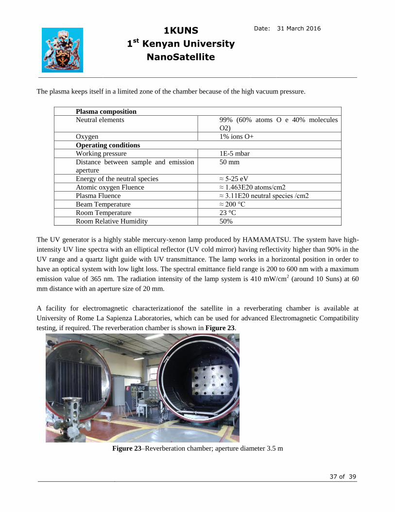
A facility for electromagnetic characterizationof the satellite in a reverberating chamber is available at
University of Rome La Sapienza Laboratories, which can be used for advanced Electromagnetic Compatibility
testing, if required. The reverberation chamber is shown in Figure 23.
Figure 23–Reverberation chamber; aperture diameter 3.5 m

1KUNS
1st Kenyan University
NanoSatellite
Date: 31 March 2016
38 of 39
3.5 Financial Plan
All the facilities of University of Rome will be put at disposal of the project in the framework of University of
Nairobi and University of Rome “La Sapienza” agreement.
The financial support is ensured by the Italian Space Agency by specific additional grant in the framework of the
IKUNS project.
3.6 Ground operation plan, including a maintenance plan for the ground station
The 1KUNS-PF nanosatellite will use the radio-amateur frequencies in the VHF and UHF radio-amateur bands.
University of Nairobi will have access to an amateur ground station which is under installation at the Broglio
Space Center in Malindi, Kenya. The ground station will be completed within July 2016, in the framework of the
IKUNS program, financed by ASI.
Students and personnel of University of Nairobi will have full access to the University of Rome ground station
located in Rome, Italy. Both direct and remote access will be allowed for the 1KUNS-PF program.
In addition, University of Roma has access to a network of amateur satellite ground stations operated by Italian
and international radio-amateurs (e.g Cesena-Bologna, Italy, and Toms River-NJ USA), for contingency
operations and for redundancy.
The Ground station of S5Lab in Rome and radio amateur ground stations in Cesena and Toms River are shown
in Figure 24.
Figure 24–Ground stations in Rome-IT, Cesena –ITandToms River (NJ) USA
3.7 Plan for frequency license
Radio-amateur frequencies will be used for the telecommunication, VHF in uplink and UHF in downlink. If
required, the National Space Secretariat of Kenya and the Italian Space Agency will support the request for
frequency license in coordination with the ICT and Radio Communication Authorities of the respective countries
(e.g. Ministry of Information and Communications and Technology). No obstacles are foreseen.

1KUNS
1st Kenyan University
NanoSatellite
Date: 31 March 2016
39 of 39
3.8 Outreach/Capacity-building
All the activities will be disseminated among students of both Nairobi and Rome University. Media will be
interested in the framework of international cooperation and scientific institutions as Italian Space Agencies will
be involved in organizing seminaries and meeting.
The Kenyan institutions will benefit of the 1KUNS-PF project having the possibility to develop their very first
nanosatellite.
3.9 Supplementary notes
The 1KUNS-PF program is included in the IKUNS (Italian-Kenyan University Nanosatellite) project, already
funded by the Italian Space Agency. The two countries have an Agreement for cooperation in space activity and
specifically in space training and education. The nanosatellite proposed is a tangible result of the international
cooperation and capacity building in space activityinitiative between Kenya and Italy..
3.10 References
- Jacopo Piattoni, Gian Paolo Candini, GiulioPezzi, Fabio Santoni, FabrizioPiergentili, “Plastic Cubesat: An
innovative and low-cost way to perform applied space research and hands-on education” ActaAstronautica,
Volume 81, Issue 2, December 2012, Pages 419–429, doi: http://dx.doi.org/10.1016/j.actaastro.2012.07.030.
- Gian Paolo Candini, FabrizioPiergentili, Fabio Santoni, “Miniaturized attitude control system for nanosatellites”,
ActaAstronautica, Volume 81, Issue 1, December 2012, Pages 325–334, doi:
http://dx.doi.org/10.1016/j.actaastro.2012.07.027
- F. Graziani, Piergentili F, Santoni F (2010). A space standards application to university-class microsatellites: the
UNISAT experience. ACTA ASTRONAUTICA, vol. 66, p. 1534-1543, ISSN: 0094-5765, doi:
10.1016/j.actaastro.2009.11.020
- Battagliere M. L., Santoni F., Piergentili F., Ovchinnikov M., Graziani F. (2010). Passive magnetic attitude
stabilization system of the EduSAT microsatellite. PROCEEDINGS OF THE INSTITUTION OF MECHANICAL
ENGINEERS. PART G, JOURNAL OF AEROSPACE ENGINEERING, vol. 224, p. 1097-1106, ISSN: 0954-
4100, doi: 10.1243/09544100JAERO732
- F. Piergentili, M. L. Battagliere, M. Porfilio, C. Portelli (2010). Italian Contribution To European Space
Surveillance: Feasibility Of Establishing Automatic Observatories At The MalindiAsi Base In Kenya And In
Argentinean Andes Mountains. In: 61° International Astronautical Congress. INTERNATIONAL
ASTRONAUTICAL CONGRESS: IAC PROCEEDINGS, International Astronautical Federation, ISSN: 1995-
6258, Prague, October 2010
- F. Santoni, F. Piergentili, F. Graziani (2009). The UNISAT program: Lessons learned and achieved results. ACTA
ASTRONAUTICA, vol. 65, p. 54-60, ISSN: 0094-5765, doi: 10.1016/j.actaastro.2009.01.072
- F. Graziani, G. Pulcrano, M. L. Battagliere, F. Piergentili, F. Santoni, G. Mascetti (2009). Design of a Small
Educational Satellite for the italian high school students: The EduSAT Project. In: 7th IAA Symposium on small
satellites for Earth Observation . Berlin, Germany , May 4 8, 2009,
- F. Graziani, F. Santoni, F.Piergentili, M.L. Battagliere, F.Guarducci, F.Paolillo, L.Ridolfi, C.Cappelletti (2009).
UniCubeSat. In: 6th Annual CubeSat Developers' Workshop . Cal Poly Campus - San Luis Obispo, CA, USA,
April 22 - 25, 2009