2 photogrammetry history of early developments1 · history of photogrammetry early developments1...
TRANSCRIPT
2
HISTORY OF PHOTOGRAMMETRY
EARLY DEVELOPMENTS1
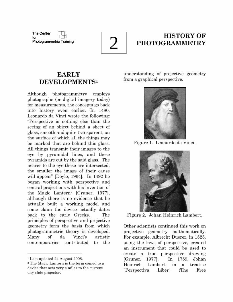
Although photogrammetry employs photographs (or digital imagery today) for measurements, the concepts go back into history even earlier. In 1480, Leonardo da Vinci wrote the following: “Perspective is nothing else than the seeing of an object behind a sheet of glass, smooth and quite transparent, on the surface of which all the things may be marked that are behind this glass. All things transmit their images to the eye by pyramidal lines, and these pyramids are cut by the said glass. The nearer to the eye these are intersected, the smaller the image of their cause will appear” [Doyle, 1964]. In 1492 he began working with perspective and central projections with his invention of the Magic Lantern2 [Gruner, 1977], although there is no evidence that he actually built a working model and some claim the device actually dates back to the early Greeks. The principles of perspective and projective geometry form the basis from which photogrammetric theory is developed. Many of da Vinci’s artistic contemporaries contributed to the
1 Last updated 24 August 2008. 2 The Magic Lantern is the term coined to a device that acts very similar to the current day slide projector.
understanding of projective geometry from a graphical perspective.
Figure 1. Leonardo da Vinci.
Figure 2. Johan Heinrich Lambert.
Other scientists continued this work on projective geometry mathematically. For example, Albrecht Duerer, in 1525, using the laws of perspective, created an instrument that could be used to create a true perspective drawing [Gruner, 1977]. In 1759, Johan Heinrich Lambert, in a treatise "Perspectiva Liber" (The Free

Center for Photogrammetric Training History of Photogrammetry Page 2
Perspective), developed the mathematical principles of a perspective image using space resection to find a point in space from which a picture is made. The relationship between projective geometry and photogrammetry was first developed by R. Sturms and Guido Hauck in Germany in 1883. [Doyle, 1964]
Figure 3. Albrecht Duerer
Figure 4. Woodcut by Duerer The
Draughtsman And The Lute from his book: 'Treatise on Mensuration with
the Compass and Ruler in Lines, Planes, and Whole Bodies' (1525)
The first photograph was obtained by Joseph Nicephone Niépce (1765-1833). The positive image Niépce required an eight-hour exposure. In 1837, Jacques Mandé Daguerre obtained the first "practical" photograph using a process called the Daguerreotype. Around 1840, the French geodesist Dominique François Jean Arago began to advocate the use of "photogrammetry", using the daguerreotype, in front of the French Arts and Science Academy.
Figure 5. J. N. Niepce.
Figure 6. Jacques Daguerre.
Center for Photogrammetric Training History of Photogrammetry Page 3
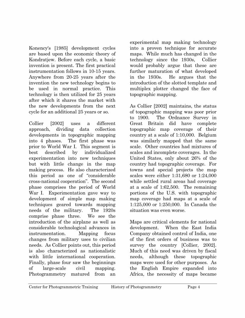
Figure 7. Photogrammetric
perspective by Hauck.
Figure 8. Dominique François Jean
Arago.
DEVELOPMENT CYCLES The developments in photogrammetry, from around 1850, have followed four development cycles [Konecny, 1985]. Each of these periods extended about fifty years. These cycles include:
a) Plane table photogrammetry,
from about 1850 to 1900, b) Analog photogrammetry, from
about 1900 to 1960, c) Analytical photogrammetry,
from about 1960 to present, and d) Digital photogrammetry, which
is just beginning to be a presence in the photogrammetric industry.
Center for Photogrammetric Training History of Photogrammetry Page 4
Konency's [1985] development cycles are based upon the economic theory of Kondratjew. Before each cycle, a basic invention is present. The first practical instrumentation follows in 10-15 years. Anywhere from 20-25 years after the invention the new technology begins to be used in normal practice. This technology is then utilized for 25 years after which it shares the market with the new developments from the next cycle for an additional 25 years or so. Collier [2002] uses a different approach, dividing data collection developments in topographic mapping into 4 phases. The first phase was prior to World War I. This segment is best described by individualized experimentation into new techniques but with little change in the map making process. He also characterized this period as one of “considerable cross-national cooperation”. The second phase comprises the period of World War I. Experimentation gave way to development of simple map making techniques geared towards mapping needs of the military. The 1920s comprise phase three. We see the introduction of the airplane as well as considerable technological advances in instrumentation. Mapping focus changes from military uses to civilian needs. As Collier points out, this period is also characterized as nationalistic with little international cooperation. Finally, phase four saw the beginnings of large-scale civil mapping. Photogrammetry matured from an
experimental map making technology into a proven technique for accurate maps. While much has changed in the technology since the 1930s, Collier would probably argue that these are further maturation of what developed in the 1930s. He argues that the introduction of the slotted template and multiplex plotter changed the face of topographic mapping. As Collier [2002] maintains, the status of topographic mapping was poor prior to 1900. The Ordnance Survey in Great Britain did have complete topographic map coverage of their country at a scale of 1:10,000. Belgium was similarly mapped that the same scale. Other countries had mixtures of scales and incomplete coverages. In the United States, only about 26% of the country had topographic coverage. For towns and special projects the map scales were either 1:31,680 or 1:24,000 while settled rural areas had coverage at a scale of 1:62,500. The remaining portions of the U.S. with topographic map coverage had maps at a scale of 1:125,000 or 1:250,000. In Canada the situation was even worse. Maps are critical elements for national development. When the East India Company obtained control of India, one of the first orders of business was to survey the country [Collier, 2002]. Much of this need was driven by fiscal needs, although these topographic maps were used for other purposes. As the English Empire expanded into Africa, the necessity of maps became

Center for Photogrammetric Training History of Photogrammetry Page 5
quickly apparent. A report of the Colonial Survey Committee identified the importance of maps [from Collier, 2002]:
The purposes for which maps are required in the administration of a country (especially an undeveloped country such as a protectorate in Tropical Africa) are many and varied. Maps are necessary to define the exact limits of national territory, to show the areas and villages under the rule of native chiefs, they are essential for land registration and settlement, for the allotment of mining and forest concessions, and for the organization of internal communications. Of their necessity in was the experiences of the army in South Africa afford an eloquent testimony; and even the conduct of a “small war” or a police expedition is much simplified by the existence of reliable maps of the scene of operation.
While there are some noted exceptions as we will see later, the almost universal method of creating topographic maps in 1900 was by ground survey. Indeed, as Collier [2002] identifies, mapping techniques in 1900 were almost the same as they were in 1800. Instruments were refined and more accurately manufactured, but the techniques were the same for all intents and purposes.
PLANE TABLE PHOTOGRAMMETRY
Figure 9. Aimé Laussedat medal.
In 1849, Aimé Laussedat (April 19, 1819 - March 18, 1907) was the first person to use terrestrial photographs for topographic map compilation. He is referred to as the "Father of Photogrammetry". The process Laussedat used was called iconometry [icon (Greek) meaning image, -metry (Greek) which is the art, process, or science of measuring]. In 1858, he experimented with aerial photography supported by a string of kites but abandoned it a couple of years later. In 1862, Laussedat's use of photography for mapping was officially accepted by the Science Academy in Madrid. He also tried balloon photography and is the first person to have captured an image from balloons, but deserted it because of the difficulty of obtaining a sufficient number of photographs to cover all of the area from one air station [Birdseye, 1940]. At the Paris Exposition in 1867, Laussedat exhibited the first known

Center for Photogrammetric Training History of Photogrammetry Page 6
phototheodolite and his plan of Paris derived from his photographic surveys. These maps were comparable to earlier maps compiled from conventional field surveys which showed that this new technology could be used for mapping. Plane table photogrammetry is an extension of the conventional plane table surveying [Konecny, 1985]. Each exposure station was determined by resection and plotted on the plane table. The exposed photos were oriented on the plane table and the directions to the different objects were transferred onto the map sheets.
Figure 10. Nadar obtaining photography from a balloon.
With the advent of photography and the ability to make exposures from the air, it was soon found that there were military applications to this technology. In 1855, Nadar (Gaspard Felix
Tournachon) used a balloon at 80-meters to obtain the first aerial photograph. In 1859 the Emperor Napoleon ordered Nadir to obtain reconnaissance photography in preparation of the Battle of Solferino. In the Franco-Prussian War during the 1870s, the Prussian army installed a photo field detachment to obtain stereophotos, most notably of the fortification of Strasbourg [Gruner, 1977]. Paulo Ignazio Pietro Porro (November 25, 1801 – October 8, 1875) was an Italian geodesist and optical engineer. As a geodesist, he invented the first tacheometer (his instrument was called a tachymeter) in 1839. In 1847 he was able to improve image quality of a lens system all the way to the edges by using three asymmetrical lens elements. He also developed an erecting lens imaging system in 1854. Porro developed a panoramic camera in 1858 that was equipped with a sighting telescope, compass, and level. The image was recorded on sensitized paper mounted on a cylinder [Birdseye, 1940]. In 1865 he designed the photogoniometer. This development is significant in photogrammetry because of its application in removing lens distortion. His approach was to look at the image with a telescope through the camera lens. This concept was also independently considered by Carl Koppe (1884-1910). Therefore, this concept is called the Porro-Koppe Principle.
Center for Photogrammetric Training History of Photogrammetry Page 7
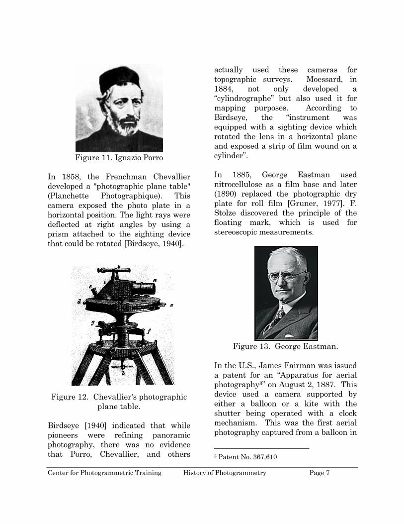
Figure 11. Ignazio Porro
In 1858, the Frenchman Chevallier developed a "photographic plane table" (Planchette Photographique). This camera exposed the photo plate in a horizontal position. The light rays were deflected at right angles by using a prism attached to the sighting device that could be rotated [Birdseye, 1940].
Figure 12. Chevallier's photographic
plane table. Birdseye [1940] indicated that while pioneers were refining panoramic photography, there was no evidence that Porro, Chevallier, and others
actually used these cameras for topographic surveys. Moessard, in 1884, not only developed a “cylindrographe” but also used it for mapping purposes. According to Birdseye, the “instrument was equipped with a sighting device which rotated the lens in a horizontal plane and exposed a strip of film wound on a cylinder”. In 1885, George Eastman used nitrocellulose as a film base and later (1890) replaced the photographic dry plate for roll film [Gruner, 1977]. F. Stolze discovered the principle of the floating mark, which is used for stereoscopic measurements.
Figure 13. George Eastman.
In the U.S., James Fairman was issued a patent for an “Apparatus for aerial photography3” on August 2, 1887. This device used a camera supported by either a balloon or a kite with the shutter being operated with a clock mechanism. This was the first aerial photography captured from a balloon in
3 Patent No. 367,610

Center for Photogrammetric Training History of Photogrammetry Page 8
the U.S. On December 12, 1893, Cornele B. Adams was given a patent for his “Method of Photogrammetry4”. His approach was to obtain two aerial photos of the same area with a camera from two positions of a captured balloon [Birdseye, 1940]. Adams also invented radial line triangulation in an effort to graphically solve the principles in plane table photogrammetry to his balloon imagery.
Figure 14. Albrecht Meydenbauer
[from Meyer, 1987]. In 1893, Dr. Albrecht Meydenbauer (April 30, 1834 - November 15, 1921) was the first person to use the term "photogrammetry". He founded the Royal Prussian Photogrammetric Institute and served as its director until 1909. Meydenbauer is known for his architectural surveys using photogrammetry. Believing that current cameras were not suitable for
4 Patent No. 510,758.
photogrammetry, he designed his first camera in 1867. This was the first wide-angle lens used for mapping – 105o Pantoshop lens. It was used for the topographic map of Freyburg, Germany, and the structural drawing of St. Mary’s Church. The camera has the following characteristics that are found in metric cameras [Meyer, 1987, p.184]:
• “sturdy body, • permanently mounted lens, • spirit levels for leveling up the
camera, • device for aligning the camera
axis, and • definition of the image plane by
a frame with fiducial marks for the coordinate axes.”
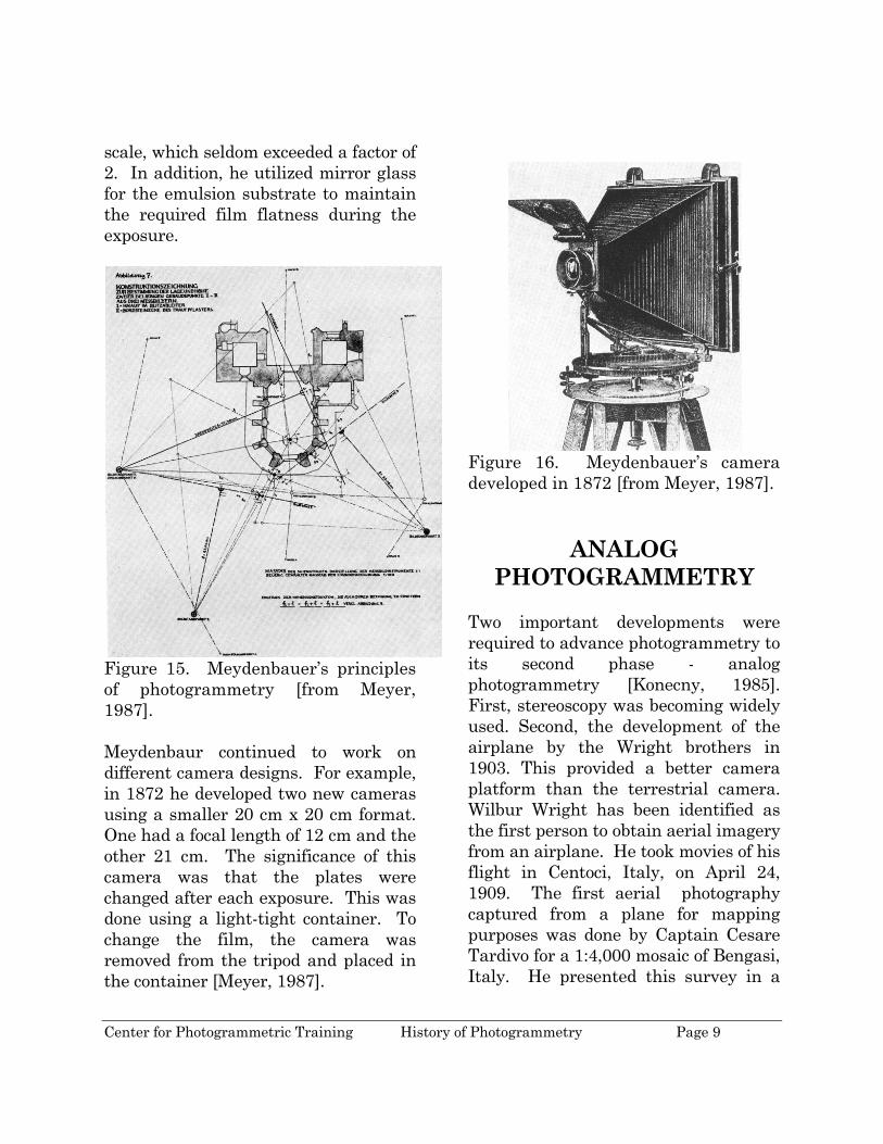
Meydenbauer’s method of map compilation utilized the approach at that time. The photograph was used to map the terrain by intersection. Directions from ground control points were graphically plotted from the imagery. Conventional surveying was used to locate the position of the cameras and a few control points in the scene being photographed. According to Meyer [1987], a good draftsperson could obtain the photographic coordinates using dividers to an accuracy of about 0.1 mm. The resulting map would have an accuracy of about 0.2 mm. High accuracy was achieved in Meydenbauer’s methods because he used a large format size (40 cm x 40 cm) and his selection of the ratio between the photo scale and map
Center for Photogrammetric Training History of Photogrammetry Page 9
scale, which seldom exceeded a factor of 2. In addition, he utilized mirror glass for the emulsion substrate to maintain the required film flatness during the exposure.
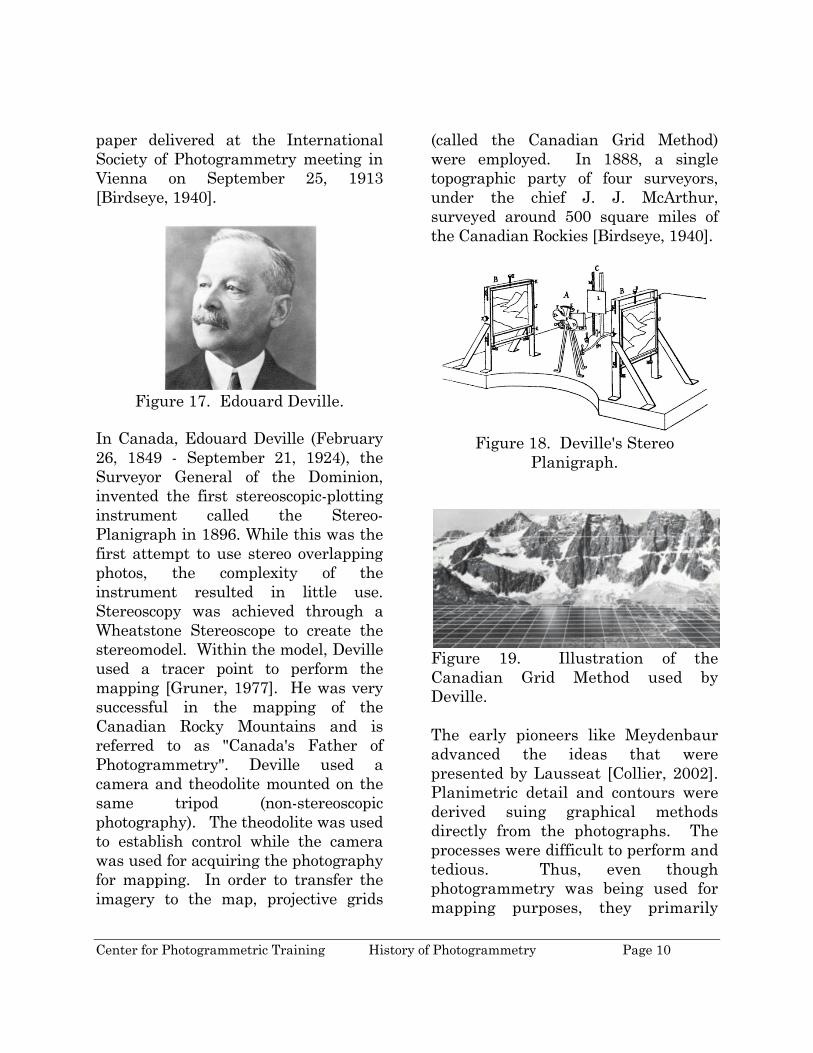
Figure 15. Meydenbauer’s principles of photogrammetry [from Meyer, 1987]. Meydenbaur continued to work on different camera designs. For example, in 1872 he developed two new cameras using a smaller 20 cm x 20 cm format. One had a focal length of 12 cm and the other 21 cm. The significance of this camera was that the plates were changed after each exposure. This was done using a light-tight container. To change the film, the camera was removed from the tripod and placed in the container [Meyer, 1987].
Figure 16. Meydenbauer’s camera developed in 1872 [from Meyer, 1987].
ANALOG PHOTOGRAMMETRY
Two important developments were required to advance photogrammetry to its second phase - analog photogrammetry [Konecny, 1985]. First, stereoscopy was becoming widely used. Second, the development of the airplane by the Wright brothers in 1903. This provided a better camera platform than the terrestrial camera. Wilbur Wright has been identified as the first person to obtain aerial imagery from an airplane. He took movies of his flight in Centoci, Italy, on April 24, 1909. The first aerial photography captured from a plane for mapping purposes was done by Captain Cesare Tardivo for a 1:4,000 mosaic of Bengasi, Italy. He presented this survey in a
Center for Photogrammetric Training History of Photogrammetry Page 10
paper delivered at the International Society of Photogrammetry meeting in Vienna on September 25, 1913 [Birdseye, 1940].
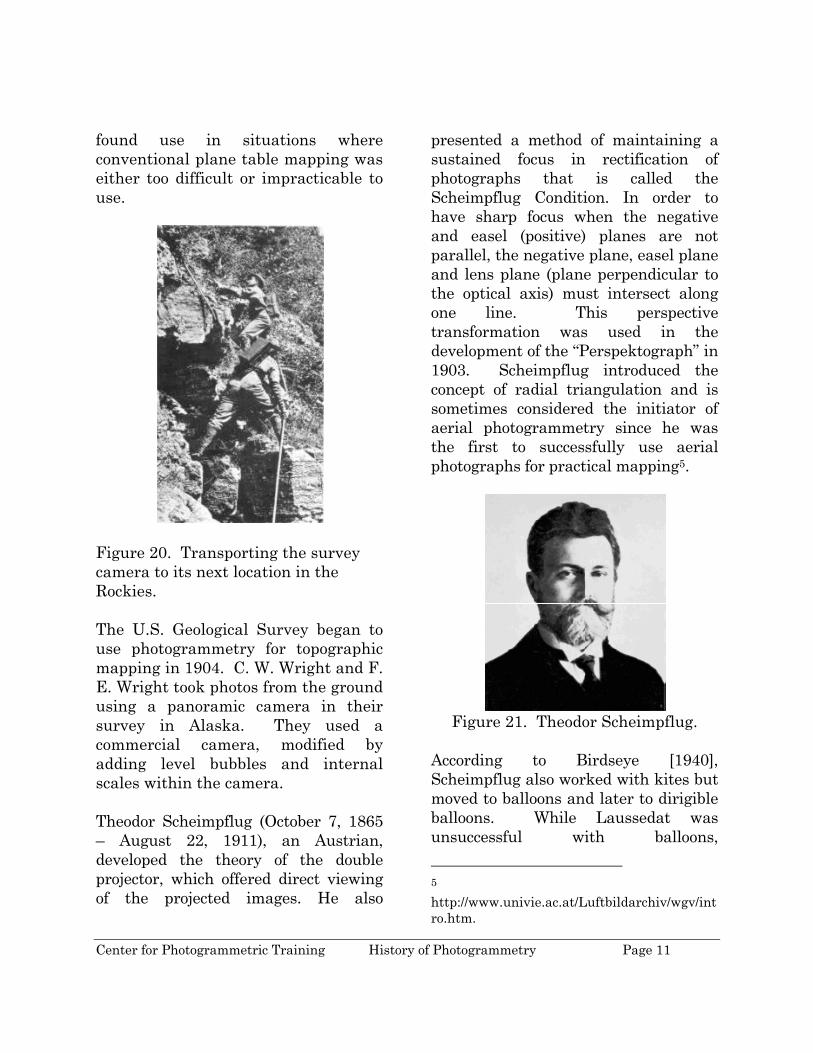
Figure 17. Edouard Deville.
In Canada, Edouard Deville (February 26, 1849 - September 21, 1924), the Surveyor General of the Dominion, invented the first stereoscopic-plotting instrument called the Stereo-Planigraph in 1896. While this was the first attempt to use stereo overlapping photos, the complexity of the instrument resulted in little use. Stereoscopy was achieved through a Wheatstone Stereoscope to create the stereomodel. Within the model, Deville used a tracer point to perform the mapping [Gruner, 1977]. He was very successful in the mapping of the Canadian Rocky Mountains and is referred to as "Canada's Father of Photogrammetry". Deville used a camera and theodolite mounted on the same tripod (non-stereoscopic photography). The theodolite was used to establish control while the camera was used for acquiring the photography for mapping. In order to transfer the imagery to the map, projective grids
(called the Canadian Grid Method) were employed. In 1888, a single topographic party of four surveyors, under the chief J. J. McArthur, surveyed around 500 square miles of the Canadian Rockies [Birdseye, 1940].
Figure 18. Deville's Stereo
Planigraph.
Figure 19. Illustration of the Canadian Grid Method used by Deville. The early pioneers like Meydenbaur advanced the ideas that were presented by Lausseat [Collier, 2002]. Planimetric detail and contours were derived suing graphical methods directly from the photographs. The processes were difficult to perform and tedious. Thus, even though photogrammetry was being used for mapping purposes, they primarily
Center for Photogrammetric Training History of Photogrammetry Page 11
found use in situations where conventional plane table mapping was either too difficult or impracticable to use.
Figure 20. Transporting the survey camera to its next location in the Rockies. The U.S. Geological Survey began to use photogrammetry for topographic mapping in 1904. C. W. Wright and F. E. Wright took photos from the ground using a panoramic camera in their survey in Alaska. They used a commercial camera, modified by adding level bubbles and internal scales within the camera. Theodor Scheimpflug (October 7, 1865 – August 22, 1911), an Austrian, developed the theory of the double projector, which offered direct viewing of the projected images. He also
presented a method of maintaining a sustained focus in rectification of photographs that is called the Scheimpflug Condition. In order to have sharp focus when the negative and easel (positive) planes are not parallel, the negative plane, easel plane and lens plane (plane perpendicular to the optical axis) must intersect along one line. This perspective transformation was used in the development of the “Perspektograph” in 1903. Scheimpflug introduced the concept of radial triangulation and is sometimes considered the initiator of aerial photogrammetry since he was the first to successfully use aerial photographs for practical mapping5.
Figure 21. Theodor Scheimpflug.
According to Birdseye [1940], Scheimpflug also worked with kites but moved to balloons and later to dirigible balloons. While Laussedat was unsuccessful with balloons, 5 http://www.univie.ac.at/Luftbildarchiv/wgv/intro.htm.

Center for Photogrammetric Training History of Photogrammetry Page 12
Scheimpflug developed a multi-lens camera in 1900 that consisted of a central vertical lens surrounded by seven oblique lenses. This gave him some very wide angle composite photography with which to work. One of the issues with balloons is the effect of wind on the flight line. The dirigible balloon gave the pilot better control over the flight direction. This led to the expansion of aerial photogrammetry in Europe.
Figure 22. Sebastian Finsterwalder Beginning in 1899, the German Sebastian Finsterwalder began to publish papers on analytical photogrammetry. When studying the resection of single and double points in space, he showed the existence of a critical surface for single-point resection. Using vector terminology, Finsterwalder showed the analytical conditions that must be met for rays to intersect. In 1899, Finsterwalder6 6 The title of the paper was "Die geometrischen Grundlagen der Photogrammetrie" (Fundamental Geometry of Photogrammetry).
described the principles of modern double-image photogrammetry and the methodology of relative and absolute orientation. In addition, he introduced the necessity of redundant rays to recreate the proper geometry and used least squares theory to describe the relationship of the vectors between corresponding rays [Doyle 1964].
In 1901, Dr. Carl Pulfrich (September 24, 1858 - August 12, 1929), a German physicist, designed the first stereocomparator employing x and y coordinate scales and presented the results at the 73rd Conference of Natural Science and Physicians in Hamburg [Doyle, 1964]. This was the first photogrammetric instrument manufactured by Zeiss. Pulfrich is sometimes referred to as the "Father of Stereophotogrammetry".
Figure 23. Dr. Carl Pulfrich.
What was remarkable about Pulfrich was his research on stereoscopy and stereoscopic instrumentation despite the fact that he had no vision in his left eye. One of the unique optical

Center for Photogrammetric Training History of Photogrammetry Page 13
phenomenon, called the Pulfrich effect7, deals with the apparent stereo effect that photogrammetrists first noticed when rapid movements of the plated containing the imagery on the stereoautograph. Believing it was a design flaw in the instrument, Zeiss assigned two individuals, Franke (an engineer) and F. Fertsch (a technician) to determine the effect. Fertsch found that this apparent stereo effect was due to the difference in brightness by the two eyes [Christianson and Hofstetter, 1972]. At about the same time, Dr. Henry George Fourcade8 (July 8, 1865 - 7 The Pulfrich effect is often described in terms of a pendulum experiment. For example, take a pair of sunglasses and take the lens out of one of the sides. Then, fixate on the pendulum with one eye looking through a darkened glass. Perception through the dark glass is slightly slower thus it would appear that the objects are in different positions yielding a three-dimensional effect. 8 There has been a lot of debate over the years as to whether Pulfrich or Fourcade developed the concept of stereophogrammetry. The debate stems from the fact that Pulfrich presented his ideas at a meeting of the “Naturforscher” on September 23, 1901 in Hamburg [Atkinson, 1980]. The title of the presentation was “Über einen für astronomische, photogrammetrisce, metronomische und andere Zwecke bestimmten stereoskopischen Komparator”. On October 2, 1901, Fourcade presented a paper in Cape Town, South Africa, at the South African Philosophical Society [Adams, 1975; Atkinson, 1980]. His paper was titled “On a stereoscopic method of photographic surveying”. Pulfrich’s paper was subsequently published in Zeitschrift für Instrumentenkunde in March, May and
January 19, 1948), from South Africa, independently developed a similar stereocomparator. The main difference is that Fourcade utilized grid plates instead of x and y coordinates. He was also the first to discuss the need for reseau in a surveying camera for use with the measuring stereoscope. Because of the independent development, many refer to the stereocomparator as the Pulfrich-Fourcade stereocomparator.
Figure 24. Dr. Henry George
Fourcade. Collier [2002] indicates that the two instruments were capable of making accurate stereoscopic measurements. They also required a lot of interpolation of the measurements because the pan
August 1902. Fourcade’s paper was published in the Transactions of the South African Philosophical Society in 1901 and also in Nature in 1902. The noted photogrammetrist Otto von Gruber identifies Pulfrich as the developer of stereophotogrammetry using Fourcade’s article in Nature as proof the Pulfrich was first [Collier, 2002].
Center for Photogrammetric Training History of Photogrammetry Page 14
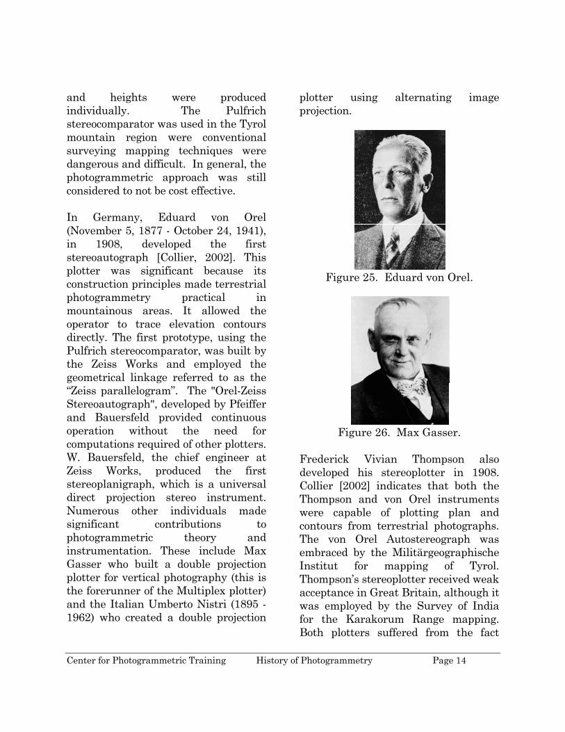
and heights were produced individually. The Pulfrich stereocomparator was used in the Tyrol mountain region were conventional surveying mapping techniques were dangerous and difficult. In general, the photogrammetric approach was still considered to not be cost effective. In Germany, Eduard von Orel (November 5, 1877 - October 24, 1941), in 1908, developed the first stereoautograph [Collier, 2002]. This plotter was significant because its construction principles made terrestrial photogrammetry practical in mountainous areas. It allowed the operator to trace elevation contours directly. The first prototype, using the Pulfrich stereocomparator, was built by the Zeiss Works and employed the geometrical linkage referred to as the “Zeiss parallelogram”. The "Orel-Zeiss Stereoautograph", developed by Pfeiffer and Bauersfeld provided continuous operation without the need for computations required of other plotters. W. Bauersfeld, the chief engineer at Zeiss Works, produced the first stereoplanigraph, which is a universal direct projection stereo instrument. Numerous other individuals made significant contributions to photogrammetric theory and instrumentation. These include Max Gasser who built a double projection plotter for vertical photography (this is the forerunner of the Multiplex plotter) and the Italian Umberto Nistri (1895 - 1962) who created a double projection
plotter using alternating image projection.
Figure 25. Eduard von Orel.
Figure 26. Max Gasser.
Frederick Vivian Thompson also developed his stereoplotter in 1908. Collier [2002] indicates that both the Thompson and von Orel instruments were capable of plotting plan and contours from terrestrial photographs. The von Orel Autostereograph was embraced by the Militärgeographische Institut for mapping of Tyrol. Thompson’s stereoplotter received weak acceptance in Great Britain, although it was employed by the Survey of India for the Karakorum Range mapping. Both plotters suffered from the fact

Center for Photogrammetric Training History of Photogrammetry Page 15
that they could not be adapted for aerial photography since each instrument required coplanar
photography, a situation that rarely existed in aerial photography.
Figure 27. von Orel's patent for Stereoisohypsograph.
Center for Photogrammetric Training History of Photogrammetry Page 16
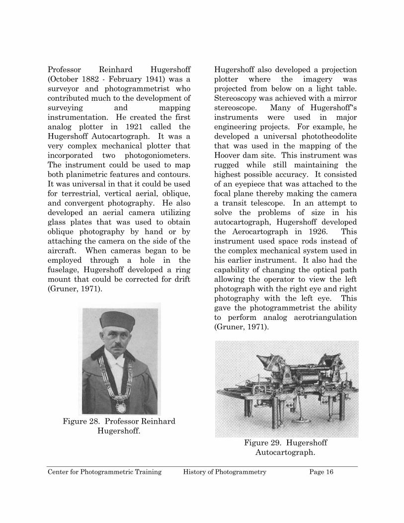
Professor Reinhard Hugershoff (October 1882 - February 1941) was a surveyor and photogrammetrist who contributed much to the development of surveying and mapping instrumentation. He created the first analog plotter in 1921 called the Hugershoff Autocartograph. It was a very complex mechanical plotter that incorporated two photogoniometers. The instrument could be used to map both planimetric features and contours. It was universal in that it could be used for terrestrial, vertical aerial, oblique, and convergent photography. He also developed an aerial camera utilizing glass plates that was used to obtain oblique photography by hand or by attaching the camera on the side of the aircraft. When cameras began to be employed through a hole in the fuselage, Hugershoff developed a ring mount that could be corrected for drift (Gruner, 1971).
Figure 28. Professor Reinhard
Hugershoff.
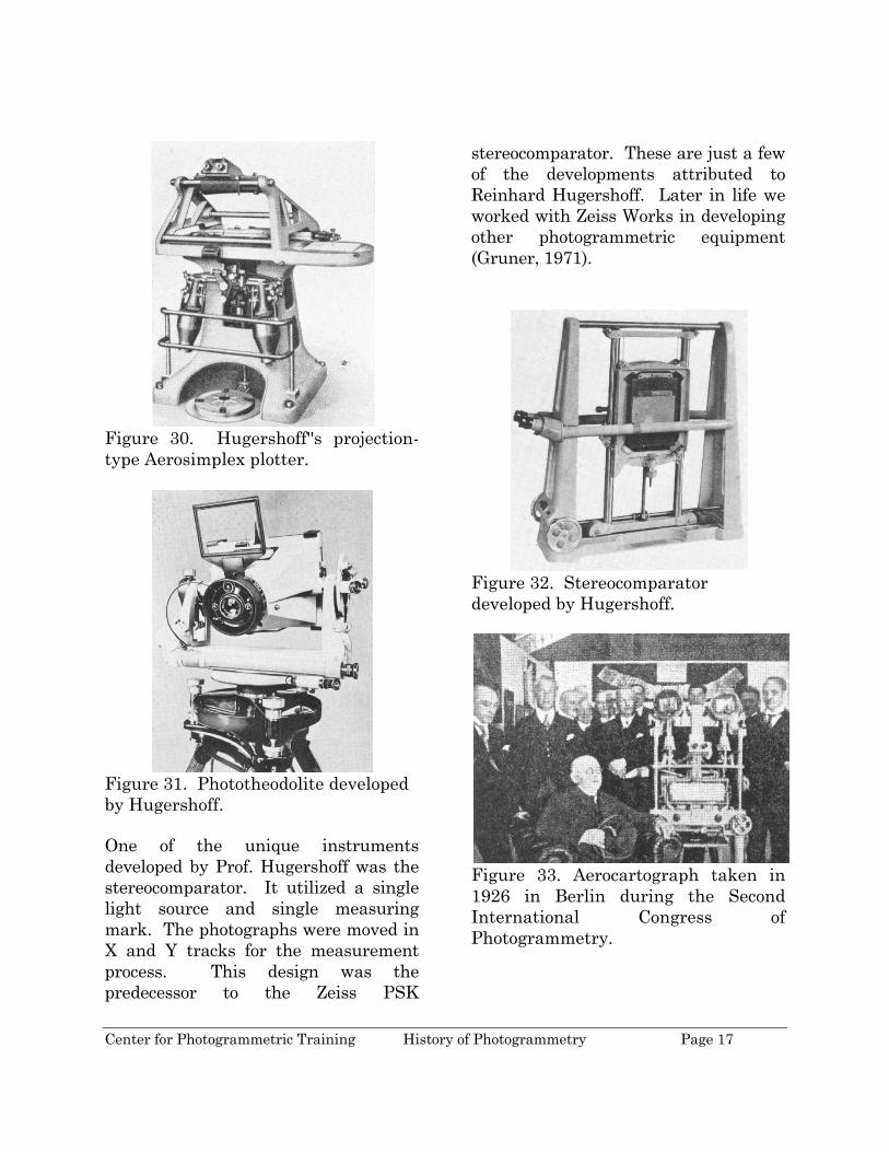
Hugershoff also developed a projection plotter where the imagery was projected from below on a light table. Stereoscopy was achieved with a mirror stereoscope. Many of Hugershoff’'s instruments were used in major engineering projects. For example, he developed a universal phototheodolite that was used in the mapping of the Hoover dam site. This instrument was rugged while still maintaining the highest possible accuracy. It consisted of an eyepiece that was attached to the focal plane thereby making the camera a transit telescope. In an attempt to solve the problems of size in his autocartograph, Hugershoff developed the Aerocartograph in 1926. This instrument used space rods instead of the complex mechanical system used in his earlier instrument. It also had the capability of changing the optical path allowing the operator to view the left photograph with the right eye and right photography with the left eye. This gave the photogrammetrist the ability to perform analog aerotriangulation (Gruner, 1971).
Figure 29. Hugershoff
Autocartograph.
Center for Photogrammetric Training History of Photogrammetry Page 17
Figure 30. Hugershoff''s projection-type Aerosimplex plotter.
Figure 31. Phototheodolite developed by Hugershoff. One of the unique instruments developed by Prof. Hugershoff was the stereocomparator. It utilized a single light source and single measuring mark. The photographs were moved in X and Y tracks for the measurement process. This design was the predecessor to the Zeiss PSK
stereocomparator. These are just a few of the developments attributed to Reinhard Hugershoff. Later in life we worked with Zeiss Works in developing other photogrammetric equipment (Gruner, 1971).
Figure 32. Stereocomparator developed by Hugershoff.
Figure 33. Aerocartograph taken in 1926 in Berlin during the Second International Congress of Photogrammetry.
Center for Photogrammetric Training History of Photogrammetry Page 18
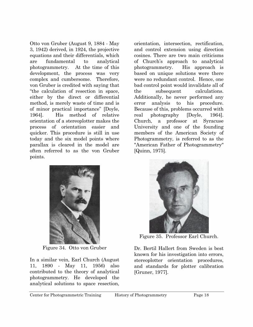
Otto von Gruber (August 9, 1884 - May 3, 1942) derived, in 1924, the projective equations and their differentials, which are fundamental to analytical photogrammetry. At the time of this development, the process was very complex and cumbersome. Therefore, von Gruber is credited with saying that “the calculation of resection in space, either by the direct or differential method, is merely waste of time and is of minor practical importance” [Doyle, 1964]. His method of relative orientation of a stereoplotter makes the process of orientation easier and quicker. This procedure is still in use today and the six model points where parallax is cleared in the model are often referred to as the von Gruber points.
Figure 34. Otto von Gruber
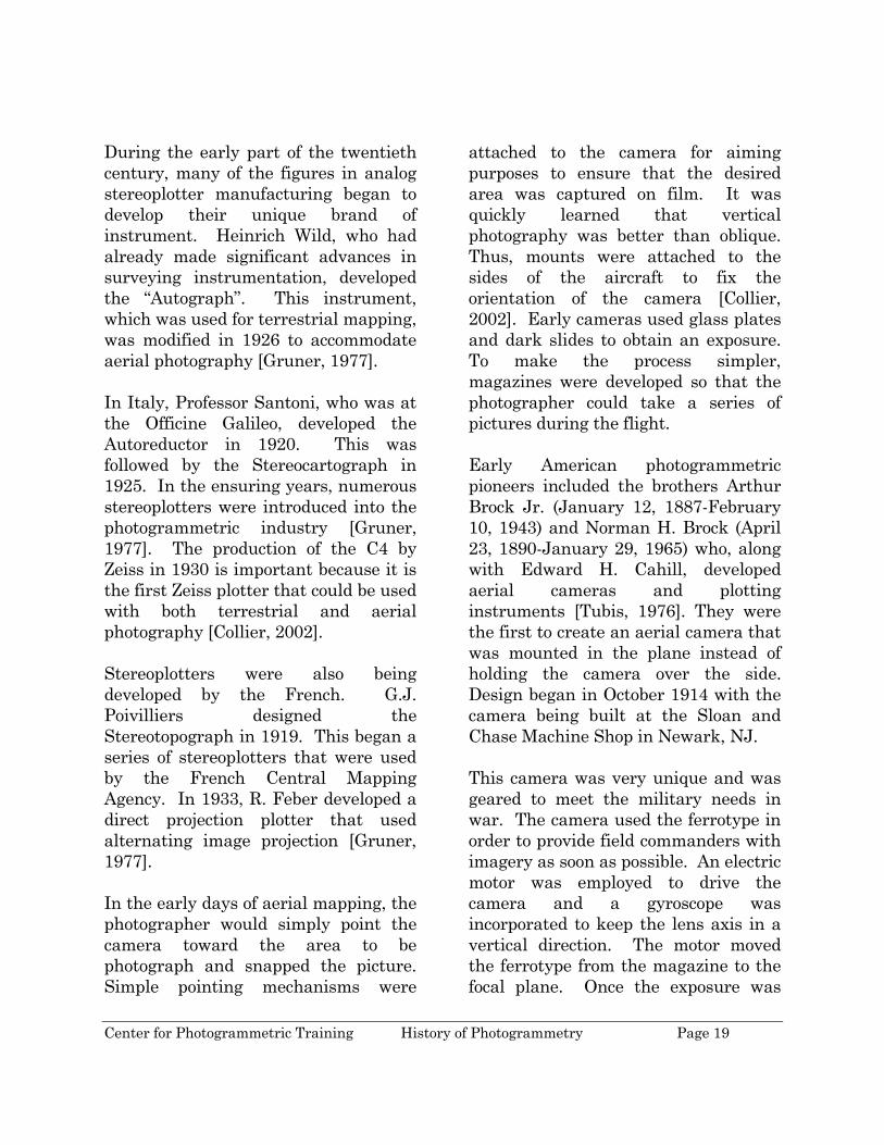
In a similar vein, Earl Church (August 11, 1890 - May 11, 1956) also contributed to the theory of analytical photogrammetry. He developed the analytical solutions to space resection,
orientation, intersection, rectification, and control extension using direction cosines. There are two main criticisms of Church’s approach to analytical photogrammetry. His approach is based on unique solutions were there were no redundant control. Hence, one bad control point would invalidate all of the subsequent calculations. Additionally, he never performed any error analysis to his procedure. Because of this, problems occurred with real photography [Doyle, 1964]. Church, a professor at Syracuse University and one of the founding members of the American Society of Photogrammetry, is referred to as the "American Father of Photogrammetry" [Quinn, 1975].
Figure 35. Professor Earl Church.
Dr. Bertil Hallert from Sweden is best known for his investigation into errors, stereoplotter orientation procedures, and standards for plotter calibration [Gruner, 1977].
Center for Photogrammetric Training History of Photogrammetry Page 19
During the early part of the twentieth century, many of the figures in analog stereoplotter manufacturing began to develop their unique brand of instrument. Heinrich Wild, who had already made significant advances in surveying instrumentation, developed the “Autograph”. This instrument, which was used for terrestrial mapping, was modified in 1926 to accommodate aerial photography [Gruner, 1977]. In Italy, Professor Santoni, who was at the Officine Galileo, developed the Autoreductor in 1920. This was followed by the Stereocartograph in 1925. In the ensuring years, numerous stereoplotters were introduced into the photogrammetric industry [Gruner, 1977]. The production of the C4 by Zeiss in 1930 is important because it is the first Zeiss plotter that could be used with both terrestrial and aerial photography [Collier, 2002]. Stereoplotters were also being developed by the French. G.J. Poivilliers designed the Stereotopograph in 1919. This began a series of stereoplotters that were used by the French Central Mapping Agency. In 1933, R. Feber developed a direct projection plotter that used alternating image projection [Gruner, 1977]. In the early days of aerial mapping, the photographer would simply point the camera toward the area to be photograph and snapped the picture. Simple pointing mechanisms were
attached to the camera for aiming purposes to ensure that the desired area was captured on film. It was quickly learned that vertical photography was better than oblique. Thus, mounts were attached to the sides of the aircraft to fix the orientation of the camera [Collier, 2002]. Early cameras used glass plates and dark slides to obtain an exposure. To make the process simpler, magazines were developed so that the photographer could take a series of pictures during the flight. Early American photogrammetric pioneers included the brothers Arthur Brock Jr. (January 12, 1887-February 10, 1943) and Norman H. Brock (April 23, 1890-January 29, 1965) who, along with Edward H. Cahill, developed aerial cameras and plotting instruments [Tubis, 1976]. They were the first to create an aerial camera that was mounted in the plane instead of holding the camera over the side. Design began in October 1914 with the camera being built at the Sloan and Chase Machine Shop in Newark, NJ. This camera was very unique and was geared to meet the military needs in war. The camera used the ferrotype in order to provide field commanders with imagery as soon as possible. An electric motor was employed to drive the camera and a gyroscope was incorporated to keep the lens axis in a vertical direction. The motor moved the ferrotype from the magazine to the focal plane. Once the exposure was
Center for Photogrammetric Training History of Photogrammetry Page 20
made the ferrotype was placed in a magazine that contained developer. The idea behind this design was that upon landing the pilot would take the exposed ferrotypes and place them into fresh water to stop the developing. The camera utilized a 12” focal length with an f-stop of 4.5 with a 4” x 5” image format. The final product did not include the gyroscope since it did not accurately hold the camera in a vertical direction. Moreover, the ferrotypes were replaced with cut film [Tubis, 1976]. The idea of providing an aerial camera that could give the field commanders a large amount of imagery was still important to the Brocks. In 1916 they developed another camera utilizing roll film. It could take 100 pictures per roll (4 ½” wide x about 560” long). To hold the lens in a vertical direction, it was pendulously held in a gimbal and dampened to minimize oscillations. The camera was linked to the instrument panel for the pilot to operate. They could take anywhere between 3 and 10 photographs per minute. One of the significant events associated with this camera is that it was the first war pictures taken by the U.S. Army (war with Mexico). The Brock mapping process required a number of steps. Tubis [1976, p.1025] identifies the steps as: "(a) producing aerial photographic negatives on glass plates, (b) plotting the horizontal position of the photographs, (c) horizontalizing, or tilt, correcting the
photographs, (d) contours and culture delineation, (e) scale equalizing, and (f) assembling the photographic information into final map form". This battery of operations necessitated a series of instruments including an enlarging projector, correcting projector, stereometer and tracing instrument. The imagery was captured with an aerial camera that had an interchangeable magazine that held 48 glass plates with a 6.5” x 8.5” format. The film was developed and then enlarged onto glass plates. This was done through the Enlarging Projector. The next step is to create templates of transparent paper by placing the overlapping pair of plates on a large stereoscope. These templates are created by a marking tool that perforates both the emulsion of the glass plates and the paper templates. These are done at the conjugate centers, control points, and the end of baselines determined from ground surveys. The templates are removed and used in creating a radial-line plot [Tubis, 1976]. The next step in the Brock process was to correct the imagery by creating new horizontal imagery. Cahill pointed out the difference in the Brock process and the approaches used in Europe. “The fundamental difference between the European and the Brock methods of solution is that knowledge of only the elevations of ground points is necessary in the Brock method, whereas data for
Center for Photogrammetric Training History of Photogrammetry Page 21
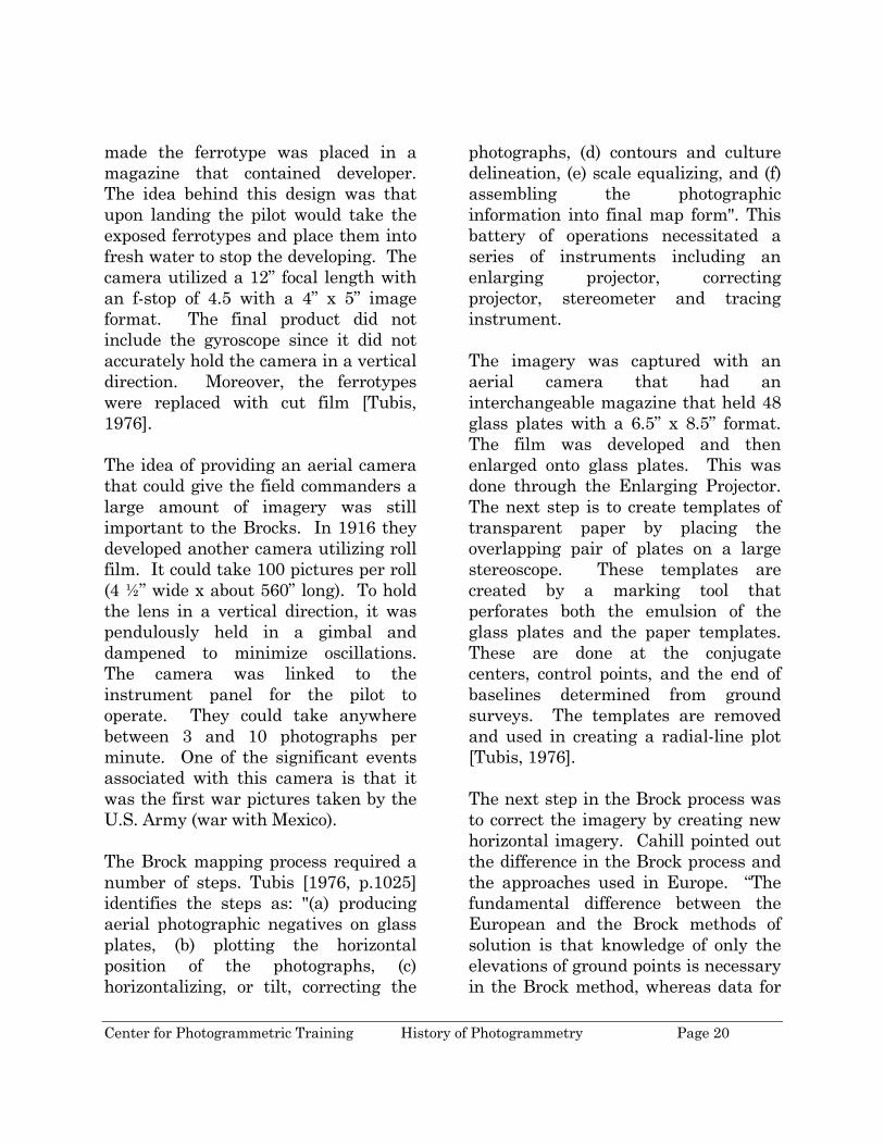
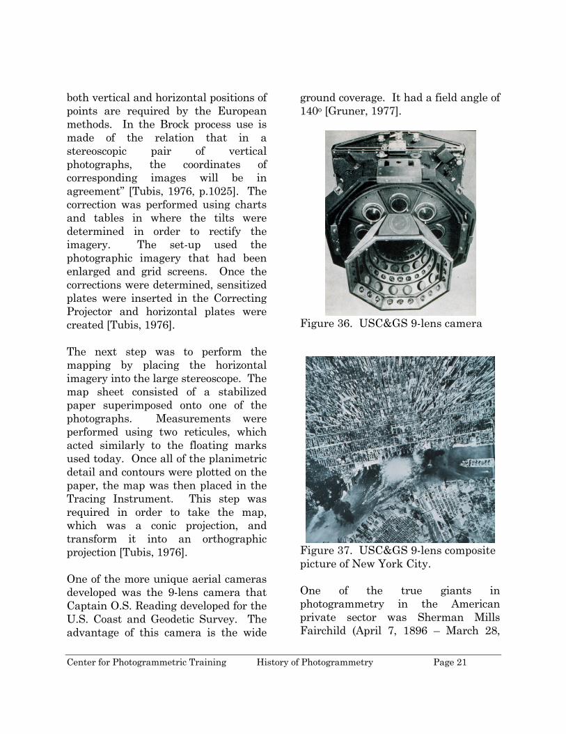
both vertical and horizontal positions of points are required by the European methods. In the Brock process use is made of the relation that in a stereoscopic pair of vertical photographs, the coordinates of corresponding images will be in agreement” [Tubis, 1976, p.1025]. The correction was performed using charts and tables in where the tilts were determined in order to rectify the imagery. The set-up used the photographic imagery that had been enlarged and grid screens. Once the corrections were determined, sensitized plates were inserted in the Correcting Projector and horizontal plates were created [Tubis, 1976]. The next step was to perform the mapping by placing the horizontal imagery into the large stereoscope. The map sheet consisted of a stabilized paper superimposed onto one of the photographs. Measurements were performed using two reticules, which acted similarly to the floating marks used today. Once all of the planimetric detail and contours were plotted on the paper, the map was then placed in the Tracing Instrument. This step was required in order to take the map, which was a conic projection, and transform it into an orthographic projection [Tubis, 1976]. One of the more unique aerial cameras developed was the 9-lens camera that Captain O.S. Reading developed for the U.S. Coast and Geodetic Survey. The advantage of this camera is the wide
ground coverage. It had a field angle of 140o [Gruner, 1977].
Figure 36. USC&GS 9-lens camera
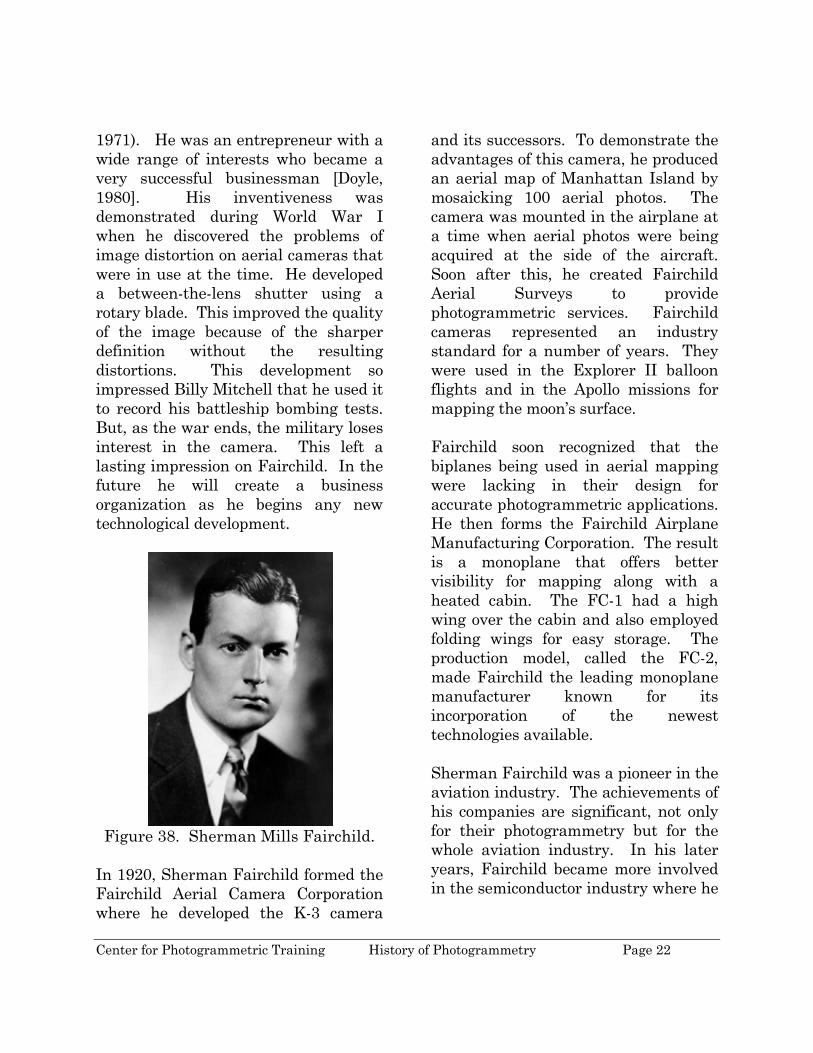
Figure 37. USC&GS 9-lens composite picture of New York City. One of the true giants in photogrammetry in the American private sector was Sherman Mills Fairchild (April 7, 1896 – March 28,
Center for Photogrammetric Training History of Photogrammetry Page 22
1971). He was an entrepreneur with a wide range of interests who became a very successful businessman [Doyle, 1980]. His inventiveness was demonstrated during World War I when he discovered the problems of image distortion on aerial cameras that were in use at the time. He developed a between-the-lens shutter using a rotary blade. This improved the quality of the image because of the sharper definition without the resulting distortions. This development so impressed Billy Mitchell that he used it to record his battleship bombing tests. But, as the war ends, the military loses interest in the camera. This left a lasting impression on Fairchild. In the future he will create a business organization as he begins any new technological development.
Figure 38. Sherman Mills Fairchild.
In 1920, Sherman Fairchild formed the Fairchild Aerial Camera Corporation where he developed the K-3 camera
and its successors. To demonstrate the advantages of this camera, he produced an aerial map of Manhattan Island by mosaicking 100 aerial photos. The camera was mounted in the airplane at a time when aerial photos were being acquired at the side of the aircraft. Soon after this, he created Fairchild Aerial Surveys to provide photogrammetric services. Fairchild cameras represented an industry standard for a number of years. They were used in the Explorer II balloon flights and in the Apollo missions for mapping the moon’s surface. Fairchild soon recognized that the biplanes being used in aerial mapping were lacking in their design for accurate photogrammetric applications. He then forms the Fairchild Airplane Manufacturing Corporation. The result is a monoplane that offers better visibility for mapping along with a heated cabin. The FC-1 had a high wing over the cabin and also employed folding wings for easy storage. The production model, called the FC-2, made Fairchild the leading monoplane manufacturer known for its incorporation of the newest technologies available. Sherman Fairchild was a pioneer in the aviation industry. The achievements of his companies are significant, not only for their photogrammetry but for the whole aviation industry. In his later years, Fairchild became more involved in the semiconductor industry where he

Center for Photogrammetric Training History of Photogrammetry Page 23
made a significant impact on the electronics field.
Figure 39. Fairchild FC-2 airplane.
Another pioneer aviator and photogrammetrist was Talbert “Ted” Abrams [August 17, 1896 – 1990]. As a boy, Ted dreamt of flying. As a young man, he joined the U.S. Marine Aviation Section. Upon discharge, he and his wife Leota formed the ABC Airborne Corporation, which was later renamed Abrams Aerial Survey Corporation. Over the years the company grew to be one of the leading photogrammetric firms in the country.
Figure 40. Talbert Abrams pilot license signed by Orville Wright.
Recognizing that airplanes were not designed with aerial mapping in mind, Ted Abrams developed the Explorer in 1937. The plane consisted of a large “glass nose, twin tail booms, a pusher engine, and a tricycle landing gear9”. In 1937, the Abrams Instrument Corporation was created to manufacture camera parts and accessories. In addition, Ted Abrams served as an advisor t the military and created the Abrams School of Aerial Surveying and Photo Interpretation.
Figure 41. Ted Abrams standing next to the Explorer airplane he developed. In 1936, Robert Ferver, from France, was awarded a U.S. patent for the Gallus-Ferber Photorestituteur which was the first orthophoto production instrument although it was not used much because it was not economical [Lawrence et al, 1968]. This plotter
9 http://www.b-295-over-korea.com/ted_abrams/ted_abrams01.html accessed 1/16/2007. Web page is written by Wayland Mayo.
Center for Photogrammetric Training History of Photogrammetry Page 24
consisted of an anaglyphic projection that was used to raise or lower one of the projectors. The movable projector did not have a filter attached to it.
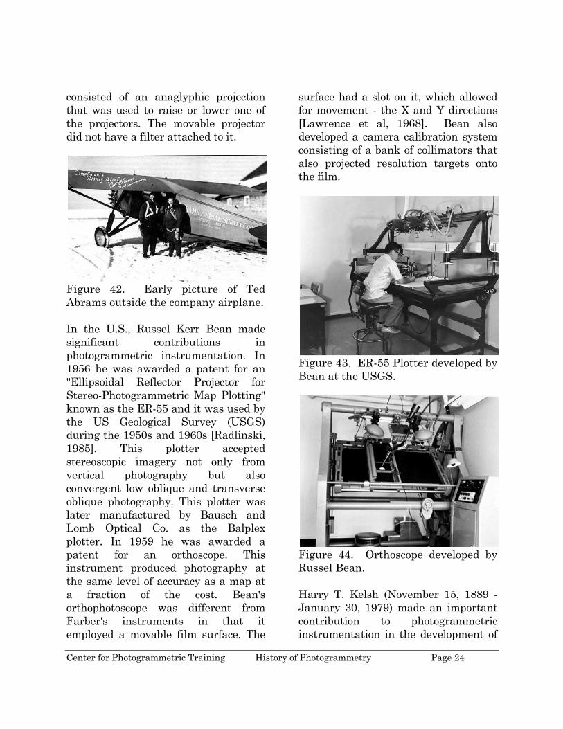
Figure 42. Early picture of Ted Abrams outside the company airplane. In the U.S., Russel Kerr Bean made significant contributions in photogrammetric instrumentation. In 1956 he was awarded a patent for an "Ellipsoidal Reflector Projector for Stereo-Photogrammetric Map Plotting" known as the ER-55 and it was used by the US Geological Survey (USGS) during the 1950s and 1960s [Radlinski, 1985]. This plotter accepted stereoscopic imagery not only from vertical photography but also convergent low oblique and transverse oblique photography. This plotter was later manufactured by Bausch and Lomb Optical Co. as the Balplex plotter. In 1959 he was awarded a patent for an orthoscope. This instrument produced photography at the same level of accuracy as a map at a fraction of the cost. Bean's orthophotoscope was different from Farber's instruments in that it employed a movable film surface. The
surface had a slot on it, which allowed for movement - the X and Y directions [Lawrence et al, 1968]. Bean also developed a camera calibration system consisting of a bank of collimators that also projected resolution targets onto the film.
Figure 43. ER-55 Plotter developed by Bean at the USGS.
Figure 44. Orthoscope developed by Russel Bean. Harry T. Kelsh (November 15, 1889 - January 30, 1979) made an important contribution to photogrammetric instrumentation in the development of

Center for Photogrammetric Training History of Photogrammetry Page 25
the Kelsh stereoplotter in 1945. This optical projection plotter offered private photogrammetrists the opportunity to perform accurate mapping without the expense that was required for the European stereoplotters. Instrument makers have had significant influences on photogrammetric developments. In 1819, Kern of Aarau, Switzerland, was founded and began manufacturing precision surveying and mapping instruments. Kern introduced the highly popular PG2 analog stereoplotter. Over 700 of these instruments were sold worldwide. In 1980, Kern introduced the DSR1 analytical stereoplotter. One of the early leading photogrammetry manufacturers was Zeiss. It’s dominance in the photogrammetry industry in the early part of the 20th century is due to the fact that many of the early pioneers were employed by the company. These individuals include von Orel, Pulfrich, Walter Bauersfeld, Willi Sandor, and von Gruber [Collier, 2002]. Some of the milestones at Zeiss in photogrammetry include: 1901 Zeiss’ first photogrammetric
instrument, the Stereo-comparator, made using the design by Pulfrich
1921 Stereoplanigraph C1 produced 1930 C4 went into production
Wild Heerbrugg was founded in 1921. They became a world leader in the manufacture of accurate surveying and mapping instruments. Their A8 and B8 Aviograph stereoplotters were very successful analog instruments with over 2,000 sold worldwide.
Figure 45. Heinrich Wild.
In 1988, Kern and Wild merged and eventually formed Leica in 1990. Using the expertise from both companies, the SD 2000 analytical plotter was launched in 1991. In 2001, Leica acquired Azimuth Corporation, ERDAS, and LH Systems giving Leica the capabilities of offering clients LIDAR scanning systems, remote sensing/image processing software packages, and digital stereoplotter capabilities.
Center for Photogrammetric Training History of Photogrammetry Page 26
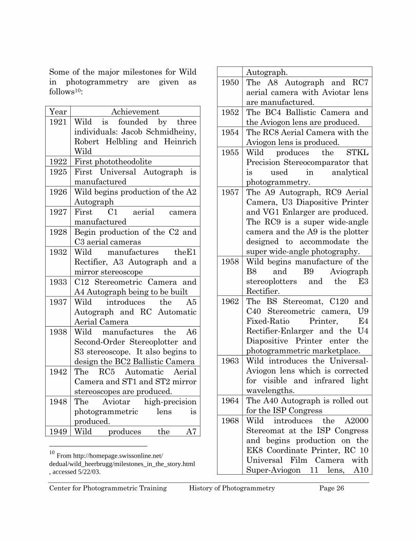
Some of the major milestones for Wild in photogrammetry are given as follows10: Year Achievement 1921 Wild is founded by three
individuals: Jacob Schmidheiny, Robert Helbling and Heinrich Wild
1922 First phototheodolite 1925 First Universal Autograph is
manufactured 1926 Wild begins production of the A2
Autograph 1927 First C1 aerial camera
manufactured 1928 Begin production of the C2 and
C3 aerial cameras 1932 Wild manufactures theE1
Rectifier, A3 Autograph and a mirror stereoscope
1933 C12 Stereometric Camera and A4 Autograph being to be built
1937 Wild introduces the A5 Autograph and RC Automatic Aerial Camera
1938 Wild manufactures the A6 Second-Order Stereoplotter and S3 stereoscope. It also begins to design the BC2 Ballistic Camera
1942 The RC5 Automatic Aerial Camera and ST1 and ST2 mirror stereoscopes are produced.
1948 The Aviotar high-precision photogrammetric lens is produced.
1949 Wild produces the A7 10 From http://homepage.swissonline.net/ dedual/wild_heerbrugg/milestones_in_the_story.html, accessed 5/22/03.
Autograph. 1950 The A8 Autograph and RC7
aerial camera with Aviotar lens are manufactured.
1952 The BC4 Ballistic Camera and the Aviogon lens are produced.
1954 The RC8 Aerial Camera with the Aviogon lens is produced.
1955 Wild produces the STKL Precision Stereocomparator that is used in analytical photogrammetry.
1957 The A9 Autograph, RC9 Aerial Camera, U3 Diapositive Printer and VG1 Enlarger are produced. The RC9 is a super wide-angle camera and the A9 is the plotter designed to accommodate the super wide-angle photography.
1958 Wild begins manufacture of the B8 and B9 Aviograph stereoplotters and the E3 Rectifier.
1962 The BS Stereomat, C120 and C40 Stereometric camera, U9 Fixed-Ratio Printer, E4 Rectifier-Enlarger and the U4 Diapositive Printer enter the photogrammetric marketplace.
1963 Wild introduces the Universal-Aviogon lens which is corrected for visible and infrared light wavelengths.
1964 The A40 Autograph is rolled out for the ISP Congress
1968 Wild introduces the A2000 Stereomat at the ISP Congress and begins production on the EK8 Coordinate Printer, RC 10 Universal Film Camera with Super-Aviogon 11 lens, A10
Center for Photogrammetric Training History of Photogrammetry Page 27
Autograph and ST10 Strip Stereoscope.
1971 The B8S Aviograph, P32 Terrestrial Camera and APK1 Panorama Camera are manufactured.
1972 New models of A8 Autograph and P31 and P32 terrestrial cameras introduced.
1976 The OR1 Avioplan begins production
1980 Wild begins manufacturing of the AC1 Aviolyt and TA2 Aviotab.
1982 Wild BC1 begins delivery. The historical developments discussed up until now involved terrestrial and aerial photogrammetric techniques. One of the unique challenges facing the scientific community was an understanding of life and features under water. Dimitri Rebikoff was born in 1921 in Paris, France. He is credited with a number of pioneering works in underwater photography including the electronic flash, film cameras and underwater photogrammetry. Collaborating with Prof. Ivanoff, Mr. Le Grad and Mr. Cuvier, he develops very accurate photogrammetric correction lenses for underwater applications11. While photogrammetric instruments were important in the development of the mapping industry, photogrammetry was dependent upon survey control to 11 http://www.rebikoff.org/historia_e.html, accessed 1/31/03.
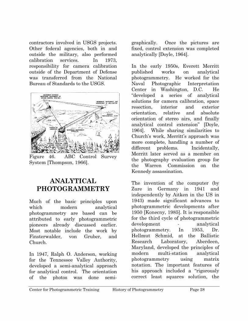
perform orient the photography and perform the necessary intersection. Control was an expensive and labor intensive operation, especially for projects encompassing large geographic areas. Numerous attempts to reduce these costs were made over the years. One such idea was the ABC (Airborne Control) Survey System invented by personnel at the U.S. Geological Survey (USGS), including Hugh “Red” Loving (1921 – 1982) who was granted a patent for the Hoversight used in the helicopter [Mullen, 2005]. This survey control method was good for lower order (fourth-order horizontal and vertical control) surveys which were sufficient for USGS topographic surveys. A helicopter would hover over a control point. The pilot would maneuver over the point using the Hoversight were directly over the point, would radio to survey personnel who were set up over at least two control points whose positions were known. They would measure the distance as well as the horizontal and vertical angles to the helicopter. On board the helicopter, a plumb line was lowered to the control point to measure the height of the helicopter over the control point. An important data collection tool, the camera is the main data acquisition tool. Its geometry needs to be recreated within the photogrammetric process to yield accurate spatial data. While many of the camera manufacturers tested and calibrated cameras, the U.S. Geological Survey began to calibrate aerial cameras in the late 1950’s for
Center for Photogrammetric Training History of Photogrammetry Page 28
contractors involved in USGS projects. Other federal agencies, both in and outside the military, also performed calibration services. In 1973, responsibility for camera calibration outside of the Department of Defense was transferred from the National Bureau of Standards to the USGS.
Figure 46. ABC Control Survey System [Thompson, 1966].
ANALYTICAL PHOTOGRAMMETRY
Much of the basic principles upon which modern analytical photogrammetry are based can be attributed to early photogrammetric pioneers already discussed earlier. Most notable include the work by Finsterwalder, von Gruber, and Church. In 1947, Ralph O. Anderson, working for the Tennessee Valley Authority, developed a semi-analytical approach for analytical control. The orientation of the photos was done semi-
graphically. Once the pictures are fixed, control extension was completed analytically [Doyle, 1964]. In the early 1950s, Everett Merritt published works on analytical photogrammetry. He worked for the Naval Photographic Interpretation Center in Washington, D.C. He “developed a series of analytical solutions for camera calibration, space resection, interior and exterior orientation, relative and absolute orientation of stereo airs, and finally analytical control extension” [Doyle, 1964]. While sharing similarities to Church’s work, Merritt’s approach was more complete, handling a number of different problems. Incidentally, Merritt later served as a member on the photography evaluation group for the Warren Commission on the Kennedy assassination. The invention of the computer (by Zure in Germany in 1941 and independently by Aitken in the US in 1943) made significant advances to photogrammetric developments after 1950 [Konecny, 1985]. It is responsible for the third cycle of photogrammetric development - analytical photogrammetry. In 1953, Dr. Hellmut Schmid, at the Ballistic Research Laboratory, Aberdeen, Maryland, developed the principles of modern multi-station analytical photogrammetry using matrix notation. The important features of his approach included a “rigorously correct least squares solution, the

Center for Photogrammetric Training History of Photogrammetry Page 29
simultaneous solution of any number of photographs, and a complete study of error propagation” [Doyle, 1964].
Figure 47. Dr. Hellmut Schmid.
Dr. Paul Herget at The Ohio State University developed a new approach to analytical control extension using vector notation (similar to the approach used by Finsterwalder). A solution was obtained by minimizing the perpendicular distances between corresponding image light rays to points on the ground. The result is that the equation for computing the ground control points had the same form as the equation used in describing the relative orientation. Herget’s method was the foundation for the Direct Geodetic Restraint Method used by the U.S. Geological Survey [Doyle, 1964]. From the National Research Council in Canada, G. H. Schut used the coplanarity concept to analytical triangulation. While an advocate for a simultaneous block adjustment, Schut recognized the limitations of computer
technology at the time and, therefore, developed a cantilever strip adjustment. This was achieved by computing, first, the relative orientation of each photograph. Next, each photograph was oriented along the strip and finally the strip coordinates were adjusted to the ground control [Doyle, 1964]. Duane Brown (August 20, 1929 – July 30, 1994) is also responsible for continued work in analytical photogrammetry while working with Schmid and later in private industry. After receiving his undergraduate degree in Mathematics from Yale University in 1951, Brown joined Schmidt at the Ballistic Research Laboratory where he was involved in geodesy using the ballistic cameras to determine the orbital path of satellites. He moved to the RCA Missile Test Project in 1955 where he developed new approaches to camera calibration and the mathematical formulation of the bundle adjustment. This is significant because it involved a simultaneous solution of the exterior orientation parameters of the camera and the coordinates of the survey points along with the interior orientation and systematic radial lens distortion. Prior to this, the exterior orientation parameters were developed independently, and then the photogrammetric intersection of the ground points was determined. His work on first order partitioned regression pioneered this algorithm to

Center for Photogrammetric Training History of Photogrammetry Page 30
many different areas of photogrammetry and geodesy.
Figure 48. Duane Brown with the CRC-1 camera [from Brown, 2005].
In 1961, Duane Brown joined the Instrument Corporation of Florida and two years later purchased the Research and Analysis Division, where he was the Director, and formed DBA (Duane Brown and Associates). DBA soon established itself as a leader in close-range photogrammetry and analytical photogrammetry. Brown continued to refine the bundle adjustment for large photogrammetric blocks to include self-calibration. The importance of self-calibration is that the accuracy and reliability of the photogrammetric adjustment improved. He recognized that the environment has an effect on the process and by calibrating the camera to extract the camera parameters in the environment in which the photography was acquired, the new camera parameters were a better representation than those derived from conventional calibration procedures. In 1962 he was able to
apply his principles to the survey of the radio telescope at Greenbank, WV. Using a modified ballistic camera, Brown was able to achieve accuracies at around the 1:50,000 level, or about 2 mm [Brown, 2005].
Figure 49. BC4 Satellite Triangulation Camera station operated by the U.S. Coast and Geodetic Survey. During his stay at DBA, the company developed a number of high-accuracy, large-format, close-range photogrammetric cameras. His work in photogrammetry also included adjusting for decentering distortion, principal point calibration, and film unflatness where he was able to show considerable deformation of glass plates. Some of the work undertaken by DBA involved mapping the moon for the Apollo program. In 1977 he founded Geodetic Services, Inc (GSI) through his purchase of the Photogrammetric and Geodetic Services Division from DBA Systems. In 1979 he was given a patent for the reseau platen that he developed. Duane Brown was also involved in
Center for Photogrammetric Training History of Photogrammetry Page 31
many geodetic activities and was sometimes referred to as “the father of the short-arc method of geodesy” [Brown, 2005]. While at GIS, Duane Brown began to prepare for the next stage that photogrammetry was moving towards. This project involved taking photogrammetry from a tool requiring highly-trained technicians to perform the measurement to a turn-key system that could be used directly by the client. This transformation required a number of tasks for GIS. The first development was the introduction of retro-reflecting targets which offered significant improvement over conventional photogrammetric targeting. Next, he helped in the mathematical development required by programmers to move the bundle adjustment software that ran on large main-frame computers to personal computers. This new software was called STARS (Simultaneous Triangulation and Resection Software). Next he developed the CRC-1 (Close-Range Camera 1) which utilized film instead of glass plates, an ultra-flat platen, back-projected reseau, and continuously focusable lens. Finally, he helped develop the AutoSet-1 monocomparator that was a faster, operator-independent, fully-automated measuring instrument. This completed the turn-key system which was also called STARS (replace Software with System). This system provided Duane Brown with the tools to achieve a milestone he was working towards –
breaking the micrometer level in photogrammetric accuracies. He was the first to achieve accuracy better than 1:1,000,000 on a project. Moreover, he helped see that use of industrial photogrammetry grow a thousand fold during the 1980s [Brown, 2005].
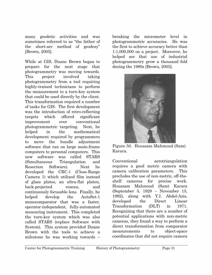
Figure 50. Houssam Mahmoud (Sam) Karara. Conventional aerotriangulation requires a good metric camera with camera calibration parameters. This precludes the use of non-metric, off-the-shelf cameras for precise work. Houssam Mahmoud (Sam) Karara (September 5, 1928 – November 15, 1992), along with Y.I. Abdel-Azis, developed the Direct Linear Transformation (DLT) in 1971. Recognizing that there are a number of potential applications with non-metric cameras, they found a way to perform a direct transformation from comparator measurements to object-space coordinates that did not require camera

Center for Photogrammetric Training History of Photogrammetry Page 32
calibration data, transformation of comparator to photo coordinates and initial approximations of unknowns. The DLT method used two polynomial equations as the basis of the transformation. These polynomials were derived from the collinearity condition and the affine coordinate transformation [Wolf, 2001]. Sam Karara was a professor at the University of Illinois at Champaign-Urbana and was widely known for his work in close-range photogrammetry. He served as editor-in-chief and author for both editions of the “Handbook on Non-Topographic Photogrammetry” published by the American Society of Photogrammetry and Remote Sensing.
Figure 51. Uuno (Uki) Helava.
The father of the analytical plotter is Uuno (Uki) Vilho Helava (March 1, 1923 – June 6, 1994). Born in Finland, Helava moved to Canada as a research fellow at the National Research Council (NRC). While at NRC, Helava developed the analytical plotter in 1957. This instrument used servocontrol instead of the optical or mechanical construction of previous instruments [Konecny, 1985]. A
computer was used not only to drive the instrument around the stereomodel but also to digitally transform coordinates between the image and the map. In 1965 Helava left the NRC and became a consultant to the Ottico Meccanica Italiana in Italy. He began working at Bendix Corporation in Southfield, Michigan in 1967 and became president of Helava and Associates, Inc. in 1979.
DIGITAL PHOTOGRAMMETRY
One of the pioneers in digital photogrammetry was Gilbert Louis Hobrough (July 26, 1918 – January 30, 2002). Born in Toronto, Ontario, he grew into a man of many interests. During his life he has been awarded at least 47 patents in such diverse areas as “phonograph turntable and pickup, high-fidelity loudspeaker design, radar and barometric altimetry, three-dimensional machine vision and laser interferometry [anon, 2003]. His photogrammetric career began with his employment at Photographic Survey Corporation Ltd. In 1951. His initial contributions to the science involved the development of an electronic dodging printer. He also built an airborne profile recorder. This instrument required a radar system to measure the range from the aircraft to the ground with about a one-foot accuracy and a reference barometer with the same comparable accuracy.
Center for Photogrammetric Training History of Photogrammetry Page 33
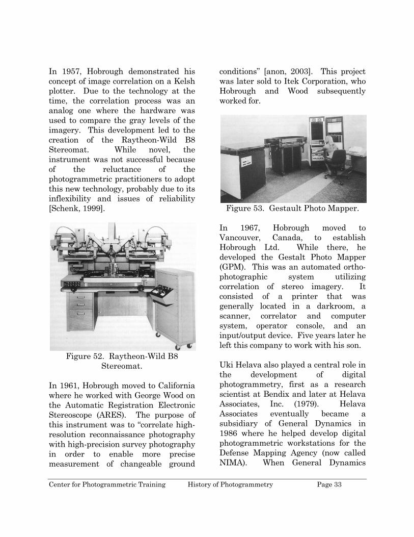
In 1957, Hobrough demonstrated his concept of image correlation on a Kelsh plotter. Due to the technology at the time, the correlation process was an analog one where the hardware was used to compare the gray levels of the imagery. This development led to the creation of the Raytheon-Wild B8 Stereomat. While novel, the instrument was not successful because of the reluctance of the photogrammetric practitioners to adopt this new technology, probably due to its inflexibility and issues of reliability [Schenk, 1999].
Figure 52. Raytheon-Wild B8
Stereomat. In 1961, Hobrough moved to California where he worked with George Wood on the Automatic Registration Electronic Stereoscope (ARES). The purpose of this instrument was to “correlate high-resolution reconnaissance photography with high-precision survey photography in order to enable more precise measurement of changeable ground
conditions” [anon, 2003]. This project was later sold to Itek Corporation, who Hobrough and Wood subsequently worked for.
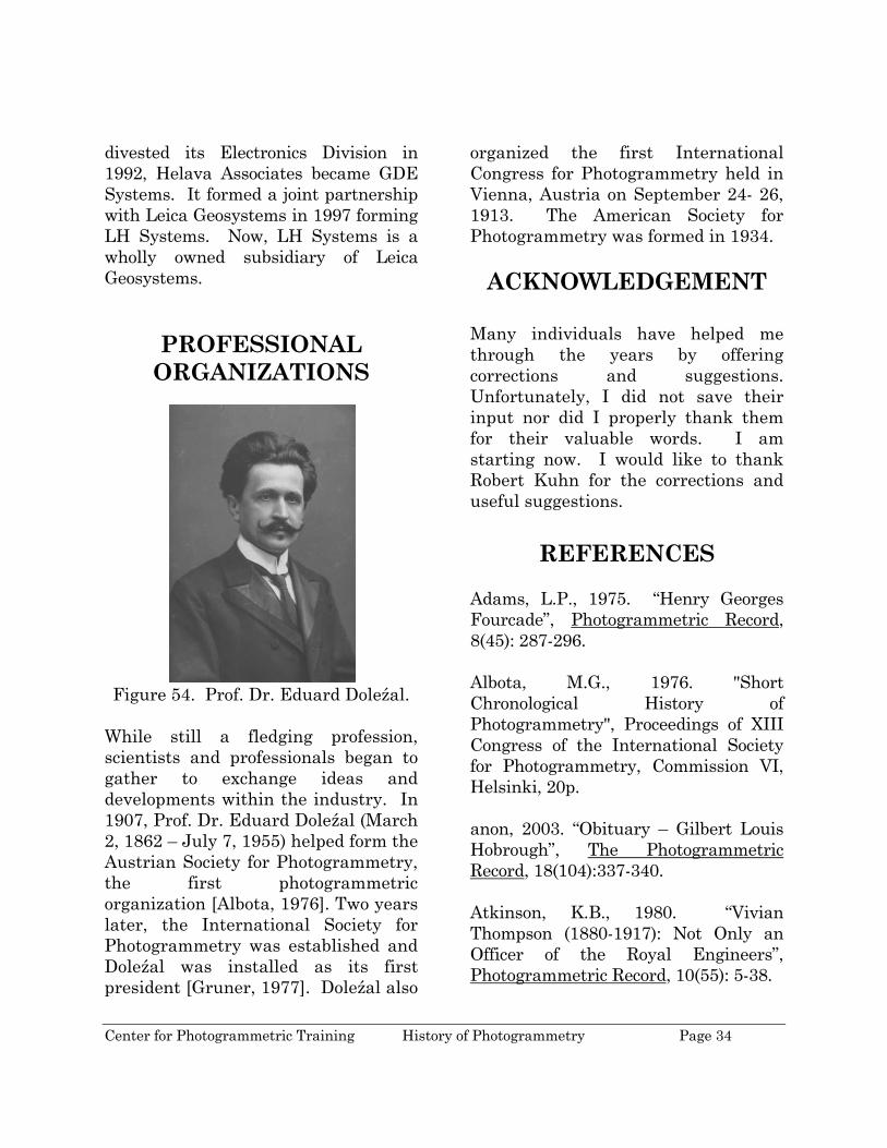
Figure 53. Gestault Photo Mapper.
In 1967, Hobrough moved to Vancouver, Canada, to establish Hobrough Ltd. While there, he developed the Gestalt Photo Mapper (GPM). This was an automated ortho-photographic system utilizing correlation of stereo imagery. It consisted of a printer that was generally located in a darkroom, a scanner, correlator and computer system, operator console, and an input/output device. Five years later he left this company to work with his son. Uki Helava also played a central role in the development of digital photogrammetry, first as a research scientist at Bendix and later at Helava Associates, Inc. (1979). Helava Associates eventually became a subsidiary of General Dynamics in 1986 where he helped develop digital photogrammetric workstations for the Defense Mapping Agency (now called NIMA). When General Dynamics
Center for Photogrammetric Training History of Photogrammetry Page 34
divested its Electronics Division in 1992, Helava Associates became GDE Systems. It formed a joint partnership with Leica Geosystems in 1997 forming LH Systems. Now, LH Systems is a wholly owned subsidiary of Leica Geosystems.
PROFESSIONAL ORGANIZATIONS
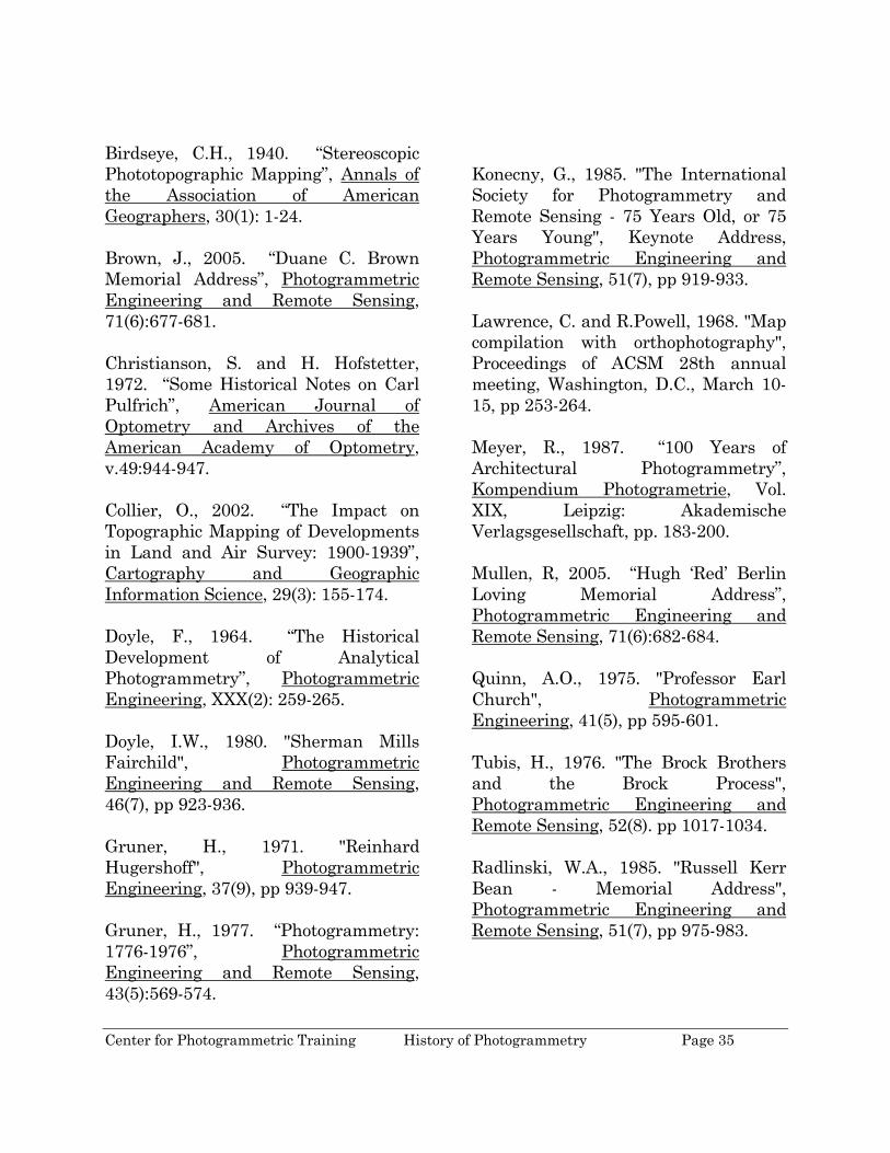
Figure 54. Prof. Dr. Eduard Doleźal.
While still a fledging profession, scientists and professionals began to gather to exchange ideas and developments within the industry. In 1907, Prof. Dr. Eduard Doleźal (March 2, 1862 – July 7, 1955) helped form the Austrian Society for Photogrammetry, the first photogrammetric organization [Albota, 1976]. Two years later, the International Society for Photogrammetry was established and Doleźal was installed as its first president [Gruner, 1977]. Doleźal also
organized the first International Congress for Photogrammetry held in Vienna, Austria on September 24- 26, 1913. The American Society for Photogrammetry was formed in 1934.
ACKNOWLEDGEMENT
Many individuals have helped me through the years by offering corrections and suggestions. Unfortunately, I did not save their input nor did I properly thank them for their valuable words. I am starting now. I would like to thank Robert Kuhn for the corrections and useful suggestions.
REFERENCES
Adams, L.P., 1975. “Henry Georges Fourcade”, Photogrammetric Record, 8(45): 287-296. Albota, M.G., 1976. "Short Chronological History of Photogrammetry", Proceedings of XIII Congress of the International Society for Photogrammetry, Commission VI, Helsinki, 20p. anon, 2003. “Obituary – Gilbert Louis Hobrough”, The Photogrammetric Record, 18(104):337-340. Atkinson, K.B., 1980. “Vivian Thompson (1880-1917): Not Only an Officer of the Royal Engineers”, Photogrammetric Record, 10(55): 5-38.
Center for Photogrammetric Training History of Photogrammetry Page 35
Birdseye, C.H., 1940. “Stereoscopic Phototopographic Mapping”, Annals of the Association of American Geographers, 30(1): 1-24. Brown, J., 2005. “Duane C. Brown Memorial Address”, Photogrammetric Engineering and Remote Sensing, 71(6):677-681. Christianson, S. and H. Hofstetter, 1972. “Some Historical Notes on Carl Pulfrich”, American Journal of Optometry and Archives of the American Academy of Optometry, v.49:944-947. Collier, O., 2002. “The Impact on Topographic Mapping of Developments in Land and Air Survey: 1900-1939”, Cartography and Geographic Information Science, 29(3): 155-174. Doyle, F., 1964. “The Historical Development of Analytical Photogrammetry”, Photogrammetric Engineering, XXX(2): 259-265. Doyle, I.W., 1980. "Sherman Mills Fairchild", Photogrammetric Engineering and Remote Sensing, 46(7), pp 923-936. Gruner, H., 1971. "Reinhard Hugershoff", Photogrammetric Engineering, 37(9), pp 939-947. Gruner, H., 1977. “Photogrammetry: 1776-1976”, Photogrammetric Engineering and Remote Sensing, 43(5):569-574.
Konecny, G., 1985. "The International Society for Photogrammetry and Remote Sensing - 75 Years Old, or 75 Years Young", Keynote Address, Photogrammetric Engineering and Remote Sensing, 51(7), pp 919-933. Lawrence, C. and R.Powell, 1968. "Map compilation with orthophotography", Proceedings of ACSM 28th annual meeting, Washington, D.C., March 10-15, pp 253-264. Meyer, R., 1987. “100 Years of Architectural Photogrammetry”, Kompendium Photogrametrie, Vol. XIX, Leipzig: Akademische Verlagsgesellschaft, pp. 183-200. Mullen, R, 2005. “Hugh ‘Red’ Berlin Loving Memorial Address”, Photogrammetric Engineering and Remote Sensing, 71(6):682-684. Quinn, A.O., 1975. "Professor Earl Church", Photogrammetric Engineering, 41(5), pp 595-601. Tubis, H., 1976. "The Brock Brothers and the Brock Process", Photogrammetric Engineering and Remote Sensing, 52(8). pp 1017-1034. Radlinski, W.A., 1985. "Russell Kerr Bean - Memorial Address", Photogrammetric Engineering and Remote Sensing, 51(7), pp 975-983.
Center for Photogrammetric Training History of Photogrammetry Page 36
Schenk, T., 1999. Digital Photogrammetry, TerraScience, Laurelville, OH, 428p. Thompson, M. (editor), 1966. Manual of Photogrammetry, 3rd edition, American Society of Photogrammetry, Falls Church, VA. Wolf, P., 2001. “Houssam Mahmoud Karara Memorial Address”,
Photogrammetric Engineering and Remote Sensing, 67(7): 811-815 Note: These notes are an outgrowth of my lecture notes on the history of photogrammetry. Because of the nature of these beginnings, some references have been inadvertently omitted and for that I apologize. Moreover, some quoted materials are not given proper acknowledgement. I welcome any corrections or additions. Any semblance of originality in this paper is by coincidence only.
RCB