2004 design guide for state aid projects - minnesota department of
TRANSCRIPT

Metro District Office of State Aid
Design Guide For
State Aid Projects
June 2017

Page 2 of 60
Table of Contents Metro District State Aid Organizational Chart 3 S.A.L.T. Organizational Chart 4 Metro State Aid Website 5 Acronyms 6-7Typical Project Time Frame 8Plans Approved at Metro State Aid 9State Aid Plan Submittal 10-12State Aid Submittal Checklist 13Request for State Aid Project Number 14-15Plan Format 16-20Signature Block 21State Aid Funding Eligibility Chart 22-24Signal Funding Options 25Bridge Funding Eligibility Chart 26-29Horizontal and Vertical Curve Design Charts 30-36Variance Information 37-39Landscape Items 40-41Signal Justification Report Information 42-48Roundabout Justification Report Information (Still being developed) 49Storm Sewer Review 50-51Pavement Design 52-56Special Provisions 57Traffic Management Plan (TMP) 57Bikeway Information 57.6XX Transport List Extensions 58General Redline Comments Observed on Plan 59-60

Federal Aid
MnDOT METRO DISTRICT STATE AID STAFF
Federal / State Aid
Construction
Dan Erickson District State Aid Engineer
651-234-7763 [email protected]
Margaret Hylton Project Manager 651-234-7767
Deb Marciniak Administrative Assistant
651-234-7701 [email protected]
Julie Dresel Metro State Aid Program
Engineer 651-234-7780
State Aid
Phil Bergem Cooperative Agreements
Engineer 651-234-7776
Cooperative Agreements
Rob Wielinski Plans Specialist 651-234-7775
Mike Pretel Construction Engineer
651-234-7778 [email protected]
Vacant Construction Specialist
651-234-7762 [email protected]
Jason Radde Project Manager 651-234-7772
Cathy Huebsch Federal Aid Engineer
651-234-7766 [email protected]
Colleen Brown Project Manager 651-234-7779
Scott Eue Project Manager 651-234-7764
Lisa Daniels
Project Manager 651-234-7774
Gennadiy Begelman
Project Manager 651-234-7761
Justin Attipou Project Manager 651-234-7768
Sharon LeMay Special Program Manager
651-234-7773 [email protected]
Vacant Statewide Jurisdictional Transfer
Program Manager 651-234-XXXX
Web Site: www.dot.state.mn.us/metro/stateaid/home.html
Agreements/Payments
Federal Aid Program
Coordinator Colleen Brown
Program Coordinator 651-234-7779
Vacant
Graduate Engineer 651-234-7769

STATE AID ENGR.
DIVISION DIRECTOR
Mitch Rasmussen
651-366-4831
DEPUTY STATE AID
ENGINEER
Ted Schoenecker
Office: 651-366-3804
Cell: 651-303-8908
STATE AID
PROGRAMS ENGR.
(Sr. Admin. Engineer)
Patti Loken
651-366-3803
MANAGER – MSAS
NEEDS STUDY
(Engineer Specialist)
Bill Lanoux
651-366-3817
MSAS NEEDS
SPECIALIST
(Transportation Specialist)
Deb Hall-Kuglin
651-366-3816
MANAGER – CSAH
NEEDS STUDY
(Sr. Engineer Specialist)
Kim DeLaRosa
651-366-3810
CSAH NEEDS
SPECIALIST
(Transportation Specialist)
John Pantelis
651-366-3811
PLANS SPECIALIST
(Engineer Specialist)
Mark Channer
651-366-3828
CONSTRUCTION
SPECIALISTS(Senior Engineering Specialist)
Ron Bumann (Districts 1-4)
218-725-2811
Rollin Larson (Districts 6-8)
507-205-6403
PROJECT DEV.
ENGINEER
(Principal Engineer)
Gary Reihl
651-366-3819
ASST. PROJECT
DEV. ENGINEER
(Senior Engineer)
Michael Scott
651-366-3825
PLANS SPECIALIST
(Sr. Engineer Specialist)
Ron Dahlquist
651-366-3823
PAVEMENT
ENGINEER
(Senior Engineer)
Joel Ulring
651-366-3831ASST. PROJECT
DEV. ENGINEER
(Sr. Engineer)
Mao Yang
651-366-3827
ASST. PROJECT
DEV. ENGINEER
(Senior Engineer)
Vacant
651-366-xxxx
DISTRICT STATE AID ENGINEERS District 1 John McDonald, 218-725-2705
District 2 Luane (Lou) Tasa, 218-755-6570
District 3 Kelvin Howieson, 218-828-5707
District 4 Nathan Gannon, 218-846-3607
District 6 Fausto Cabral, 507-286-7620
District 7 Gordon Regenscheid, 507-304-6105
District 8 Todd Broadwell, 507-537-2044
Metro Dan Erickson, 651-234-7763
ADMINISTRATIVE
ASSISTANT(Princ. Office Admin. Specialist)
Vacant
651-366-4801
State Aid for
Local TransportationMay 11, 2017
State Aid Bridge Engineer
Dave Conkel, 651-366-4493
State Aid Accountant
Ann McLellan
651-366-4877
State Aid Hydraulic Specialist
Juanita Voigt, 651-366-4469
STATE AID PROJECT
DELIVERY ENGINEER
(Sr. Admin. Engineer)
Merry Daher
651-366-3821
STATE AID
OPERATIONS ENGR.
Paul Stine
651-366-3830
WEBSITE & APPL.
SUPPORT
(Transp. Prog. Specialist 2)
Alyssa Klossner
651-366-3837
PROGRAM
SUPPORT ENGR./
DISASTER COORD
(Principal Engineer)
Mark Vizecky
651-366-3839
SPECIAL PROGRAMS
PROJECT DEV. ENGR.
( Admin.Engineer.Prof.)
Lynnette Roshell
651-366-3822
PLANS ENGINEER
(Principal Engineer)
Vacant
651-366-3826
LABOR COMPLIANCE(Transp. Prog. Team Leader)
Clancy Finnegan
651-366-4204
PROGRAM
SUPPORT ENGR.
(Sr. Engineer)
Sulmaan Khan
651-366-3829
CONSTRUCTION
ENGINEER(Principal Engineer)
Mike Pretel (Metro)
651-234-7778
Key:
= direct reports
= report to others
PROGRAM
SUPPORT
(Trans. Program Specialist)
Nancy Stone
651-366-4830
IT SERVICES MGR.
(IT Specialist 4)
Lowell Schafer
651-366-3835
PROJECT MGR/
APPLICATIONS
(IT Specialist 3)
Rick Kostohryz
651-366-3836
OFFICE ADMIN.
SUPPORT
(Trans. Program Specialist)
Olga Kruglova
651-366-3806
SPECIAL PROJECTS(Mobility)
Greg Coughlin
651-366-3815
GRADUATE
ENGINEER
(on rotation)
Chelsey Palmateer
507-304-6196
ASST. PLANS
ENGINEER
(Mobility)
Girma Feyissa
651-366-3818

Page 5 of 60
METRO STATE AID WEB SITE http://www.dot.state.mn.us/metro/stateaid/home.html
The following information/links can be obtained at the above web site. 1. What’s New - State Aid news and bulletins, including training seminar dates. 2. Meet the Staff - Staff Roster with a short explanation of their duties, phone #’s and e-mail
addresses. 3. State Aid Training - Up to date information on up-coming training seminars for State Aid,
Federal Aid and Cooperative Agreement projects. 4. Downloadable State/Federal Aid Forms - Commonly used State/Federal Aid forms. 5. Municipal Agreement Program - Check out the status of your Cooperative Agreement
projects. 6. State Aid Manual and State Aid Rules – provided as a link to SALT. 7. Standard Plates List – A listing of the current Standard Plates. 8. State Aid Contract/Final Estimate Payments - Status of your State Aid payments is at your
fingertips. 9. Federal Aid Construction 10. ADA – Metro State Aid ADA Guidelines and links for MnDOT and SALT ADA websites. Other links of Interest: 1. State Aid for Local Transportation Office (Central Office State Aid). Some information
worth checking out at their site is the State Aid Scene, information on their current staff, TRNS*PORT list (downloadable), the current State Aid Rules and the State Aid Manual.
2. Bridge and Design Standard Plans/Provisions, Metro Traffic Engineering, Preliminary Design and Mn/DOT Sample Plan.
3. “Meet the Metro County Engineers”. Here you will find the Metro County Engineers names and phone numbers.
4. Metro City Engineer list. Here you will find the Metro City Engineers names and phone numbers.

Page 6 of 60
ACRONYMS
AASHTO American Association of State Highway and Transportation Officials ADT Average Daily Traffic ATP Area Transportation Partner CA Certified Acceptance CARS Contract Administration Record System C&G Curb and Gutter CIC Capital Improvement Committee CSA County State Aid CSAH County State Aid Highway CO Central Office COE Corp Of Engineers DBE Disadvantaged Business Enterprise DE Drainage Easement DSAE District State Aid Engineer EA Environmental Assessment EAW Environmental Assessment Worksheet EEO Equal Employment Opportunity EDS Employee Development Specialist ESAL Equivalent Single Axle Load EVP Emergency Vehicle Preemption (for Signal Systems) F&P Funding And Programming FBF Federal Bridge Funds FHWA Federal Highway Administration FONSI Finding of No Significant Impact GE Granular Equivalent GRR Great River Road ICE Intersection Control Evaluation ISTEA Intermodal Surface Transportation Efficiency Act LCMR Legislative Commission on Minn Resources LPA Local Public Agency MEQB Minnesota Environmental Quality Board MMUTCD Minnesota Manual on Uniform Traffic Control Devices MnDOT Minnesota Department Of Transportation MRP Minnesota Road Plan MRPC Mississippi River Parkway Commission MSA Municipal State Aid
Page 7 of 60
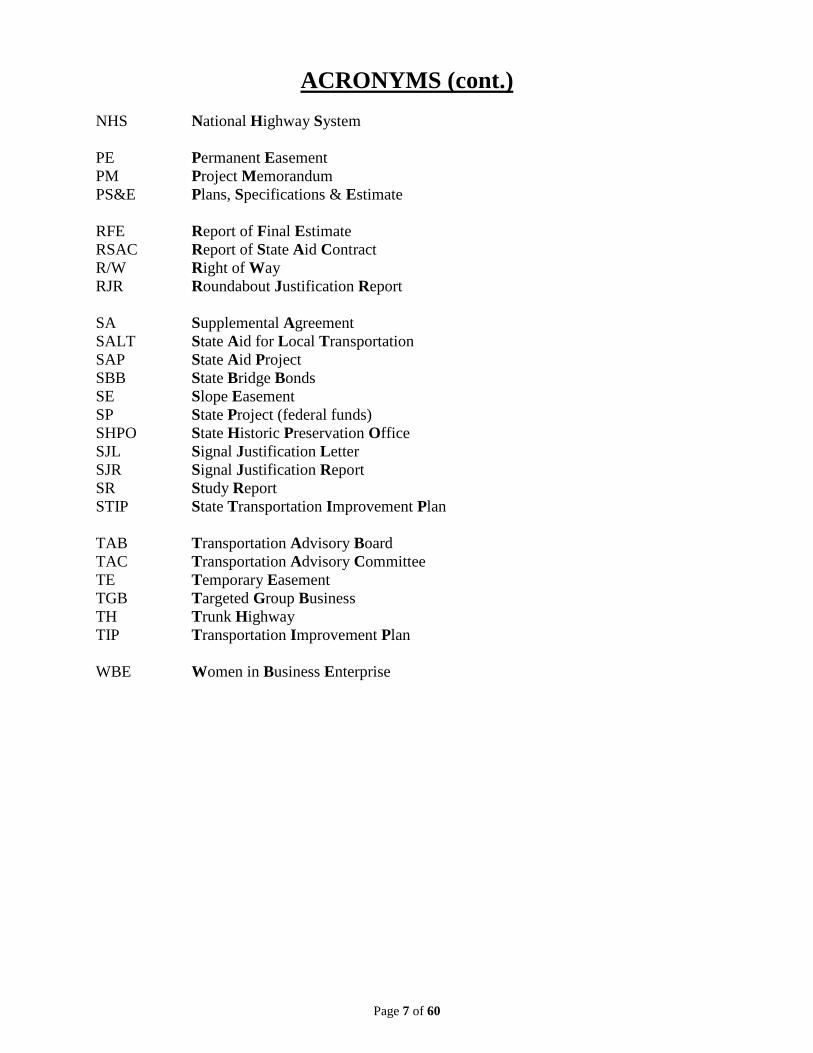
ACRONYMS (cont.)
NHS National Highway System PE Permanent Easement PM Project Memorandum PS&E Plans, Specifications & Estimate RFE Report of Final Estimate RSAC Report of State Aid Contract R/W Right of Way RJR Roundabout Justification Report SA Supplemental Agreement SALT State Aid for Local Transportation SAP State Aid Project SBB State Bridge Bonds SE Slope Easement SP State Project (federal funds) SHPO State Historic Preservation Office SJL Signal Justification Letter SJR Signal Justification Report SR Study Report STIP State Transportation Improvement Plan
TAB Transportation Advisory Board TAC Transportation Advisory Committee TE Temporary Easement TGB Targeted Group Business TH Trunk Highway TIP Transportation Improvement Plan WBE Women in Business Enterprise

Page 8 of 60
Typical Project Time Frame
Time Frame Task (responsibility) 1-4 weeks Plan submittal and log-in, first submittal reviewed by plan
reviewer, email with comments to designer (1-2 weeks) **. If the plan has a trunk highway endpoint or crossing, allow an extra 3 weeks for trunk highway routing and comments (3-4 weeks).
1-2 weeks Corrections made by the designer 1 day-1 week Final review by plan reviewer, approval or recommendation for
approval by the District State Aid Engineer. ___________ 3-7 weeks TOTAL PROJECT REVIEW AND APPROVAL TIME ** NOTE: During peak work load periods (January thru June), please allow extra time for initial plan review.
Page 9 of 60
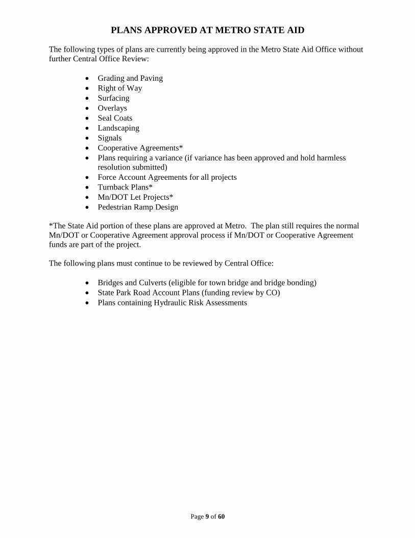
PLANS APPROVED AT METRO STATE AID
The following types of plans are currently being approved in the Metro State Aid Office without further Central Office Review:
• Grading and Paving • Right of Way • Surfacing • Overlays • Seal Coats • Landscaping • Signals • Cooperative Agreements* • Plans requiring a variance (if variance has been approved and hold harmless
resolution submitted) • Force Account Agreements for all projects • Turnback Plans* • Mn/DOT Let Projects* • Pedestrian Ramp Design
*The State Aid portion of these plans are approved at Metro. The plan still requires the normal Mn/DOT or Cooperative Agreement approval process if Mn/DOT or Cooperative Agreement funds are part of the project. The following plans must continue to be reviewed by Central Office:
• Bridges and Culverts (eligible for town bridge and bridge bonding) • State Park Road Account Plans (funding review by CO) • Plans containing Hydraulic Risk Assessments

Page 10 of 60
STATE AID PLAN SUBMITTAL For Review of Plans in the Metro Division State Aid Office
WHAT TO SUBMIT FOR INITIAL REVIEW Obtain a State Aid Project (S.A.P.) number (request form at http://www.dot.state.mn.us/stateaid/projectdelivery/project-number-request.pdf http://dotapp7.dot.state.mn.us/saasreports/Logon.aspx or by calling Margaret Hylton at 651-234-7767). See pages 13-14 for S.A.P. Number Request form. When your plan is ready to be delivered to the Metro Division State Aid Office for the first time, please provide the following items to help expedite your plan review.
1. Version of the Plan a. Send one electronic copy if the project is MSA or CSAH and does not impact
a trunk highway. b. If either endpoint is a trunk highway, adjacent to or crosses a Trunk Highway,
or a trunk highway drainage area is affected contact our office. c. One paper copy if a hydraulics percent split will be needed and you want us
to "pre-submit" to State Aid Hydraulics. See #3 below for other drainage submittal information required.
d. Submit one copy to Dave Conkel, Bridge Office, for bridges 10 feet or longer, except culverts. Obtain bridge numbers from Lisa Hartfiel at 651-366-4557 for all bridges 10 feet or longer.
For reference a checklist of the documents required for submission are listed on page 12 and explanation of each required item is listed below.
2. A COMPLETED Plan Review Checklist: Please remember to fill in rule 8820.99XX used on the Design Standard Used line and make sure the City/County has signed the checklist at the bottom of the form.
State Aid Only - No Bridge State Aid Only with Bridge
3. Drainage Area Maps and Hydraulic Computations; a. One (1) paper copy if submittal to State Aid Hydraulics is required. b. Two (2) copies (one paper, one electronic) if trunk highway endpoint or trunk
highway drainage area.
4. If using the R Value Sigma N18 method, a. A Soils / Geotechnical Report with the R Value clearly indicated. b. ESAL computations bases on ESAL factors from Geotechnical Manual.
5. If using the soil factor HCADT method, and the soil factor in the Needs
Report is higher than on the plan, substantiating evidence for the lowered soil factor.

Page 11 of 60
STATE AID PLAN SUBMITTAL (CONTINUED) 6. If the plan is for Resurfacing (Reconditioning), and vertical and horizontal
alignments have not been provided in the plan, copies of as-built plans from previous construction will be needed to verify the design speed. If the roadway was previously constructed with State Aid funds all that is required is a copy of the as built Title Sheet with signatures.
7. Engineers Estimate with cost splits shown. A separate Engineers Estimate for R/W
only if reimbursement for R/W costs is part of the plan. 8. Laboratory Testing Services Request Form, Fig. A(1) 5-892.243 of the State Aid Manual
can be found at Laboratory Testing & Plant Inspection Services Request. Please make sure to mark all services required including Structural Metal and Fabrication Methods and Fill in the TA98/99 Agreement number.
9. Hydraulic letter/Risk Assessment if applicable (for culverts 3.05m (10ft.)) or greater.
(found at Hydraulics Letters and Risk Assessments)
WHAT TO SUBMIT FOR INITIAL REVIEW
10. No Parking Resolutions for the State Aid Route if parking lanes are not provided. For resurfacing or rehabilitation projects, a copy of an inplace resolution is fine.
11. SJR (Signal Justification Report) with signature block for Metro District State Aid
Engineer, OR Signal Justification Letter and Warrant Analysis, as applicable. (See Design Guide page 13 for checklist)
12. RJR (Roundabout Justification Report) with signature block from Metro District State Aid
Engineer, as applicable.
13. Variance approval letter and Hold Harmless Resolution if a variance is required (variance checklist can be found at: http://www.dot.state.mn.us/stateaid/variance/variance-justification-checklist.pdf ).
14. If your State Aid Project impacts the Trunk Highway Right of Way in any manner, please
call Buck Craig (651-234-7911) in the Mn/DOT District Permit Office to obtain a permit to work on Mn/DOT Right of Way.
15. Submit Special Provisions if MnDOT Lab Services are requested 16. Please provide a cover letter with Contact Information including name, phone & email.
State any other information pertaining to the review that may assist with the review. Also include the City or County contact information incase specific questions arise. This contact will also be copied on the return of Review Comments.
PLEASE RETAIN THE SIGNATURE ORIGINALS UNTIL FINAL REVIEW

Page 12 of 60
STATE AID PLAN SUBMITTAL (CONTINUED) WHAT TO EXPECT IN RETURN
1. Plan review in order of turn in date.
2. Routed review if Trunk Highway impacts are possible.
3. Electronic plan review comments will be sent to the designer and the City or County contact will be copied.
4. Hydraulic Eligibility memo and comments if Drainage work is present will be sent separately.
5. List of items needed at final submission with plan.
WHAT TO INCLUDE IN THE FINAL SUBMITTAL
1. The Final Plans with signatures: a. Signature original title sheet. (media of Agency’s preference) b. One (1) electronic copy of the final plan set.
2. Revised submittal material (most often the Engineers Estimate).
3. Documentation of any additions or changes made to the plan other than those changes
made due to the comments in the review letter.

Page 13 of 60
STATE AID SUBMITTAL CHECKLIST 00-000 Plan Year ID S.A.P. ___-___-___, ___-___-___, ___-___-___, ___-___-___, ___-___-___, ___-___-___, ___-___-___ S.P. ____-___ FIRST PLAN SUBMITTAL DATE 00/00/00 FINAL PLAN SUBMITTAL DATE 00/00/00 PLAN APPROVAL DATE 00/00/00 SEE ELECTRONIC FILES FOR ITEMS Y / N REQUIRED STATE AID PLAN REVIEW CHECKLIST Rule 8820.99__ Signature Y / N ENGINEERS ESTIMATE (required for al projects) REVISED ENGINEERS ESTIMATE LABORATORY TESTING SERVICES REQUEST FORM (for all projects) TA98/99 SPECIAL PROVISION IF LAB SERVICES REQUIRED R VALUE DOCUMENTATION (for roadway type projects) ESAL CALCULATIONS (for roadway type projects) PAVEMENT DESIGN CALCULATIONS (for all roadway type projects) PARKING RESOLUTIONS (for roadway type projects that restrict parking) DRAINAGE AREA MAPS/CALCULATIONS (projects which propose storm sewer) HYDRAULIC RISK ASSESSMENT (if applicable) HYDRAULIC MEMO RECEIVED (if applicable) ___ % ELIGIBLE MnDOT PROJECT REQUIRES HYDRAULIC REVIEW SIGNAL JUSTIFICATION REPORT/LETTER (SJR/SJL) (for signal projects) SJR/SJL APPROVAL ROUNDABOUT JUSTIFICATION REPORT (for roundabout projects) RJR APPROVAL FORCE ACCOUNT PAPERS FORCE ACCOUNT APPROVAL VARIANCE APPROVAL LETTER/HOLD HARMLESS RESOLUTION (if applicable) VARIANCE APPROVAL BRIDGE REVIEW DATE SENT TO BRIDGE 00/00/00 BRIDGE APPROVAL DATE SENT FOR SIGNATURE 00/00/00 BRIDGE BOND APPLICATION 1601B SPECIAL PROVISION BRIDGE BOND FUNDING APPROVAL LETTER DATE SENT TO PATTI 00/00/00 ENGINEER’S ESTIMATE EXCEL FORMAT LRIP APPLICATION DATE SENT TO PATTI 00/00/00 LRIP FUNDING APPROVAL LETTER 1601B SPECIAL PROVISION TRUNK HIGHWAY REVIEW COMMENTS DUE BACK 00/00/00 RAIL REVIEW COMMENTS DUE BACK 00/00/00

Revised 9/14 Page 1 of 2 Page 14 of 60
New Bridge No.:
New Bridge No.:
SALT Request for State Aid Project Number
Requestor name: Phone:
Requestor email: City/County/Agency Name:
Funding types (check all that apply): ☐ Federal Aid ☐ Turnback ☐ State Park Road ☐ State Aid ☐ Disaster
Road System: ☐ CSAH ☐ Township Road ☐ Bikeway ☐ MSAS ☐ Trunk Highway ☐ Does not apply ☐ County Road ☐ Forest Highway ☐ City Street ☐ Park Road
Road No.: Road Name:
Project Location (enter beginning and end of project to know points – not stationing):
From: To: In the City of:
If not in a City, enter the distance and direction from the nearest incorporation: Distance: miles Direction: From: Legal Description (Township-Section-Range):
Tied Project Numbers (if any): (project numbers which will be on the same plan or in the same contract as this project)
Old Bridge No.:
Old Bridge No.:
Estimated construction Start date Month: Year End date Month: Year:
Additional notes:
For State Aid Office Use Only – Assigned State Aid Project No. (SAP/SAP):

Page 15 of 60
Type of work (check all that apply):
Roadway continued…Bridge/Culvert continued…Traffic Control ☐ Aggregate Base ☐ Bridge Replacement ☐ Temporary Traffic Signal ☐ Aggregate Shoulder ☐ Bridge Widening ☐ Traffic Management System ☐ Aggregate Surfacing ☐ Construction Detour Traffic Signal Cab. & Controller ☐ Bike Lane ☐ Culvert Extension ☐ Traffic Signal Installation ☐ Bituminous Base ☐ Culvert Replacement ☐ Traffic Signal Poles ☐ Bituminous Crack & Seal ☐ Culvert Replacement ☐ Traffic Signal Revision ☐ Bituminous Mill ☐ Deck Replacement ☐ Traffic Barrier ☐ Bit. Mill & Overlay ☐ Existing Alignment ☐ Warning Flasher ☐ Bituminous Overlay ☐ Joint Repair Other Facilities ☐ Bit. Pave. Replacement ☐ Mechanical Upgrade ☐ Aggregate Bike Trail ☐ Bituminous Surfacing ☐ Multiuse Trail Bridge (incl. bike) ☐ Bike Lockers ☐ Bypass Lane ☐ Multiuse Trail Underpass (incl. bike) ☐ Bike Rack ☐ Channelization ☐ New Alignment ☐ Biological Relocation ☐ Cold Inplace Recycle ☐ New Bridge ☐ Bituminous Walk ☐ Con. Crack & Joint Repair ☐ New Culvert ☐ Building Removal ☐ Concrete Mill & Overlay ☐ Overlay ☐ Bus Shelters ☐ Concrete Overlay ☐ Paint ☐ Concrete Sidewalk ☐ Con. Pave. Replacement ☐ Pedestrian Bridge ☐ Curb Ramps ☐ Concrete Surfacing ☐ Pedestrian Underpass ☐ Decorative Ped. Lighting ☐ Construct Detour ☐ Railing Replacement ☐ Decorative Roadway Lighting ☐ Culvert ☐ Skyway ☐ Erosion Control ☐ Curb & Gutter ☐ Temporary Bridge ☐ Exhibits ☐ Diagonal Parking Non-construction ☐ Fencing ☐ Drainage/Less 10 ft. Culvert ☐ Access Control ☐ Historic Building Restoration ☐ Emergency Repairs ☐ Archaeological Study ☐ Historic Preservation ☐ Erosion Repair ☐ Areawide Planning ☐ Historic Vehicle Restoration ☐ Existing Alignment ☐ Artifact Acquisition ☐ Interpretive Facilities ☐ Grading ☐ Construction Engineering ☐ Kiosks ☐ HOV Lane ☐ Corridor Management Plan ☐ Landscaping ☐ Median ☐ Corridor Study ☐ Maintain Building ☐ Micro Surfacing ☐ Design Engineering ☐ Miscellaneous Amenities ☐ New Alignment ☐ Develop Training Materials ☐ Multiuse Bit. Trail (incl. bike) ☐ Patching ☐ Marketing ☐ Noise Abatement ☐ Reconstruction ☐ Preliminary Engineering ☐ Other Local Uses ☐ Roundabout ☐ Right of Way Acquisition ☐ Other Transp. Facil. Restoration ☐ Seal Coat ☐ Scenic Easement ☐ Park and Ride ☐ Shoulder Paving ☐ Tourist Information ☐ Parking Lot ☐ Shoulder Widening ☐ Training Conference ☐ Pedestrian Lighting ☐ Slope Flattening Traffic Control ☐ Rest Area ☐ Storm Sewer ☐ Emergency Vehicle Preemption ☐ Retaining Wall ☐ Subgrade Correction ☐ Guardrail ☐ Scenic Overlook ☐ Truck Climbing lane ☐ Interconnect ☐ Street Lighting ☐ Turn Lane ☐ Railroad Crossing Signal ☐ Tourist Center ☐ Widening ☐ Railroad Crossing Surfacing ☐ Trail Head
Bridge/Culvert ☐ Ramp Meter ☐ Transit Hub ☐ Approach Panel ☐ Signal Lamp Replacement ☐ Utility Relocation ☐ Bridge Rehab ☐ Signing ☐ Wetland Mitigation ☐ Bridge Removal ☐ Striping
EMAIL THIS COMPLETE FROM TO YOUR DISTRICT STATE AID OFFICE.

Page 16 of 60
PLAN FORMAT ITEMS Use of these items in a plan presented for review in the State Aid Division will facilitate a quick review. TITLE SHEET INFORMATION
1. CONSTRUCTION PLAN FOR work description (Excavation, Agg. Base Class 5, Curb & Gutter, Bituminous Surfacing, R/W Acquisition, Storm Sewer, etc). Use pay item level of detail rather than saying a roadway name or bikeway.
2. SAP ###-###-### LOCATED ON FROM TO _____
3. PROJECT LENGTH showing exceptions if any.
Length must agree with the stationing shown on the index map. Provide a block for each SAP number, if there is more than one project number in the plan.
4. GOVERNING SPECIFICATION NOTE.
THE 2016 EDITION OF THE MINESOTA DEPARTMENT OF TRANSPORTATION “STANDARD SPECIFICATIONS FOR CONSTRUCTION” SHALL APPLY.
5. PLAN PREPARATION CERTIFICATION with License number, printed name and signature of the preparer.
Certification is now required by the Board on EACH sheet, including Standard Plan sheets where information has been added or deleted. Cross Section sheets do NOT require certification.
6. DESIGN DESIGNATION INFORMATION BLOCK
a) Show traffic dates in the year the project is to be let and adjust the figures, if appropriate. b) Traffic figures should match values shown in the needs. If the proposed roadway is of a lesser width than the amount dictated by the traffic figures in the needs, justification is needed. c) Soil factors should match the percentage shown in the needs. If the soil factor shown on the plan provides more stability than the factor shown in the needs, a soils letter and tests or borings supporting the lowered factor are required and needs updated. d) Show Exceptions to the Design Speed if less than the design speed allowed by the rules. Include the stations of the exception and the reason allowed.
DESIGN SPEED NOT ACHIEVED AT: Sta.____ to Sta.____ (reason)* A Stop Condition or lighted sag vertical curve is permitted with no variance. If the exception requires a variance include variance note.
Page 17 of 60
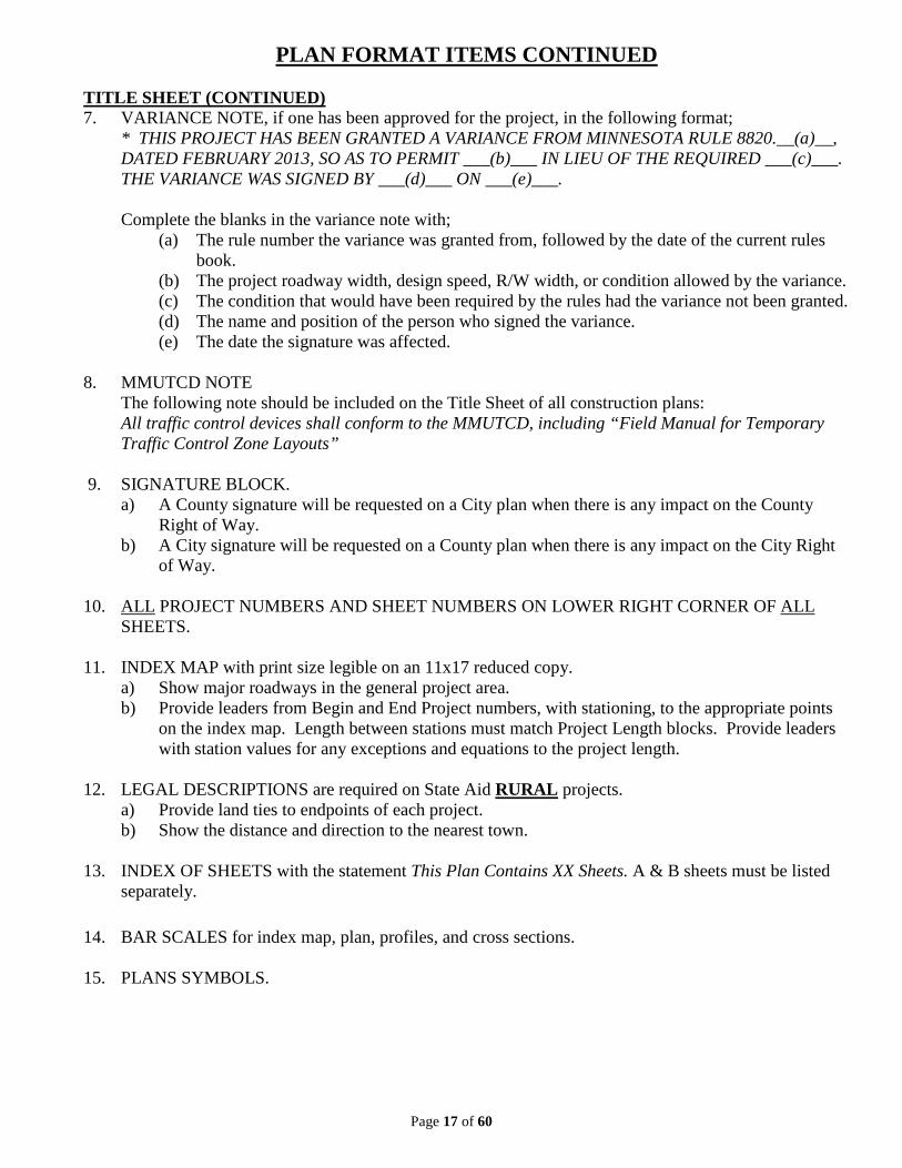
PLAN FORMAT ITEMS CONTINUED
TITLE SHEET (CONTINUED) 7. VARIANCE NOTE, if one has been approved for the project, in the following format;
* THIS PROJECT HAS BEEN GRANTED A VARIANCE FROM MINNESOTA RULE 8820.__(a)__, DATED FEBRUARY 2013, SO AS TO PERMIT ___(b)___ IN LIEU OF THE REQUIRED ___(c)___. THE VARIANCE WAS SIGNED BY ___(d)___ ON ___(e)___.
Complete the blanks in the variance note with;
(a) The rule number the variance was granted from, followed by the date of the current rules book.
(b) The project roadway width, design speed, R/W width, or condition allowed by the variance. (c) The condition that would have been required by the rules had the variance not been granted. (d) The name and position of the person who signed the variance. (e) The date the signature was affected.
8. MMUTCD NOTE
The following note should be included on the Title Sheet of all construction plans: All traffic control devices shall conform to the MMUTCD, including “Field Manual for Temporary Traffic Control Zone Layouts”
9. SIGNATURE BLOCK.
a) A County signature will be requested on a City plan when there is any impact on the County Right of Way.
b) A City signature will be requested on a County plan when there is any impact on the City Right of Way.
10. ALL PROJECT NUMBERS AND SHEET NUMBERS ON LOWER RIGHT CORNER OF ALL
SHEETS. 11. INDEX MAP with print size legible on an 11x17 reduced copy.
a) Show major roadways in the general project area. b) Provide leaders from Begin and End Project numbers, with stationing, to the appropriate points
on the index map. Length between stations must match Project Length blocks. Provide leaders with station values for any exceptions and equations to the project length.
12. LEGAL DESCRIPTIONS are required on State Aid RURAL projects.
a) Provide land ties to endpoints of each project. b) Show the distance and direction to the nearest town.
13. INDEX OF SHEETS with the statement This Plan Contains XX Sheets. A & B sheets must be listed
separately.
14. BAR SCALES for index map, plan, profiles, and cross sections.
15. PLANS SYMBOLS.

Page 18 of 60
PLAN FORMAT ITEMS CONTINUED
ESTIMATED QUANTITY SHEET
1. ITEM NUMBERS and UNITS associated with the number that matches the TRNS.PORT list, which can be found for 2016 Spec Book at http://transport.dot.state.mn.us/Reference/refItem.aspx . If item cannot be found in the TRNS.PORT list, replace the item number with a similar item number and use a .6XX extension (refer to sheet 58 for .6XX extension list) and include in the special provisions the method of measurement, payment and construction specifications, of which we would need a copy of.
2. SEPARATE COLUMNS:
a) For each SAP. b) For STORM SEWER a separate column is required for each SAP. c) For Local Funds, to pay non-participating items. If local funds are provided from different
sources (more than one city or county), a separate column for each source as necessary. d) Landscape column for Landscape items.
3. BASIS OF ESTIMATED QUANTITIES SUMMARY.
4. NOTES TO THE PAY ITEMS a) Show application rates for tack coat, fertilizer, mulch, and other quantities where the unit is not a
total measure. b) When Lump Sum items are used, state what the total includes, especially the number of trees in
Clearing and Grubbing which are needed to compute the replacement quantity by ratio.
5. TABULATIONS, consider construction location summaries for pay items like: Fence; Trees and Shrubs; Removals; Retaining Walls; Storm Sewer; and Earthwork. All quantities must be verifiable through the use of tabulations or notes on the plan.
6. EARTHWORK SUMMARY, list excavation and embankment quantities so that it is apparent how
much material is excess, if the excess is to be disposed of by the contractor or stockpiled, or, if borrow is needed to justify the quantity.
7. Do not show 0 “zero” quantities in the SEQ or Tabulations.
CONSTRUCTION NOTES
1. Include descriptions of suitable and unsuitable soils and where their placement is allowed or specified. 2. Define tapers through the base material to match an existing roadway. 3. Note if topsoil stripping and stockpiling is expected. 4. Define compaction requirements and methods.

Page 19 of 60
PLAN FORMAT ITEMS CONTINUED
STANDARD PLATES
1. FHWA NOTE. THESE STANDARD PLATES AS APPROVED BY THE FHWA SHALL APPLY.
2. CURRENT LETTER DESIGNATION for each plate number, which can be found
at http://standardplates.dot.state.mn.us/StdPlate.aspx. 3. DESCRIPTION matches the one in the manual.
4. USE A BICYCLE SAFE CASTING.
5. PROVIDE ADDITIONAL CONSTRUCTION DETAILS, for items that do not have a MnDOT
Standard Plate. 6. IF MULTIPLE SHEETS FOR PLATE, INCLUDE (X SHEETS) AFTER DESCRIPTION. TYPICAL SECTIONS
1. INDIVIDUAL LANE WIDTHS for thru lanes, turn lanes, parking lanes, and shoulder widths (rural).
2. G.E. REQUIREMENTS MET. Check total and Bituminous G.E.
3. SHOW RIGHT OF WAY WIDTH.
4. NOTE CLEAR ZONE.
5. SPECIFICATION AND DEPTH OF ROADWAY CONSTRUCTION PAY ITEMS. a) Use spec. 2360 Bituminous Quality Management items.
6. Add LABELS for: Pavement Cross Slopes; Inslopes; Ditch Widths; and Backslopes.
7. LABEL THE LOCATION OF THE PROFILE GRADE.
8. Dimension the TOPSOIL DEPTH, and label SEED AND SOD REQUIREMENTS.
9. Illustrate DITCH BOTTOM and BACKSLOPE ROUNDING. STANDARD PLAN SHEETS
1. If applicable, include Mn/DOT Standard Plan sheets as details in the plan. Standard Plan sheets are available on our web page http://standardplans.dot.state.mn.us/StdPlan.aspx
2. If changes are made to the Standard Plan sheet or any details are crossed out, a plan certification block
must be added to the sheet.

Page 20 of 60
PLAN FORMAT ITEMS (CONTINUED)
PEDESTRIAN RAMP DESIGN PLAN SHEETS
1. MnDOT Standard Plans 5-297.250 sheets 1-6 (Most Current Date Version) must be included in plan set. Along with MnDOT Standard Plate 7038. Standard Plate 7035 has been replaced with MnDOT Standard Plans 5-297.254 sheets 1-4.
2. Design guidance for ADA can be found at: http://www.dot.state.mn.us/ada/design.html If you need
assistance with Ped Ramp design, please give the ADA office a call and they will help you with your design.
3. Detail drawings for EACH Ped Ramp are preferred for State Aid projects. When the Ped Ramp is within Trunk Highway R/W, details are required and will be reviewed by MnDOT ADA Office.
PLAN SHEETS
1. HORIZONTAL and VERTICAL CURVE DATA are required to verify design speed. Show superelevation with the horizontal curve data. Plan view of the transition areas or a super chart may be used.
2. Ensure that any VARIANCE PARAMETERS have been met by the plan, if applicable.
3. Add SIGHT DISTANCE OBSTACLES such as trees and walls to the inplace topography.
4. Provide dimensions for INTERSECTION and ENTRANCE RADII.
5. Show RIGHT of WAY and TEMPORARY EASEMENT dimensions.
6. Consider showing DRAINAGE DIRECTION ARROWS.
7. Show inplace and proposed UTILITIES and DRAINAGE SYSTEMS.
8. Provide STATIONING AT CORPORATE LIMITS of municipalities.
9. Add a NORTH ARROW & SCALE to each sheet.
10. LABEL appropriate REMOVAL and CONSTRUCTION ITEMS for quantity verification..
CROSS SECTION SHEETS
1. RIGHT of WAY, PERMANENT EASEMENT and TEMPORARY EASEMENT LINES are required.
2. Show DRAINAGE PATTERNS and SPECIAL DITCH GRADES.
3. CENTERLINE AND ENTRANCE CULVERTS.
4. Cross section end areas are helpful so that earthwork quantities can be verified more quickly.
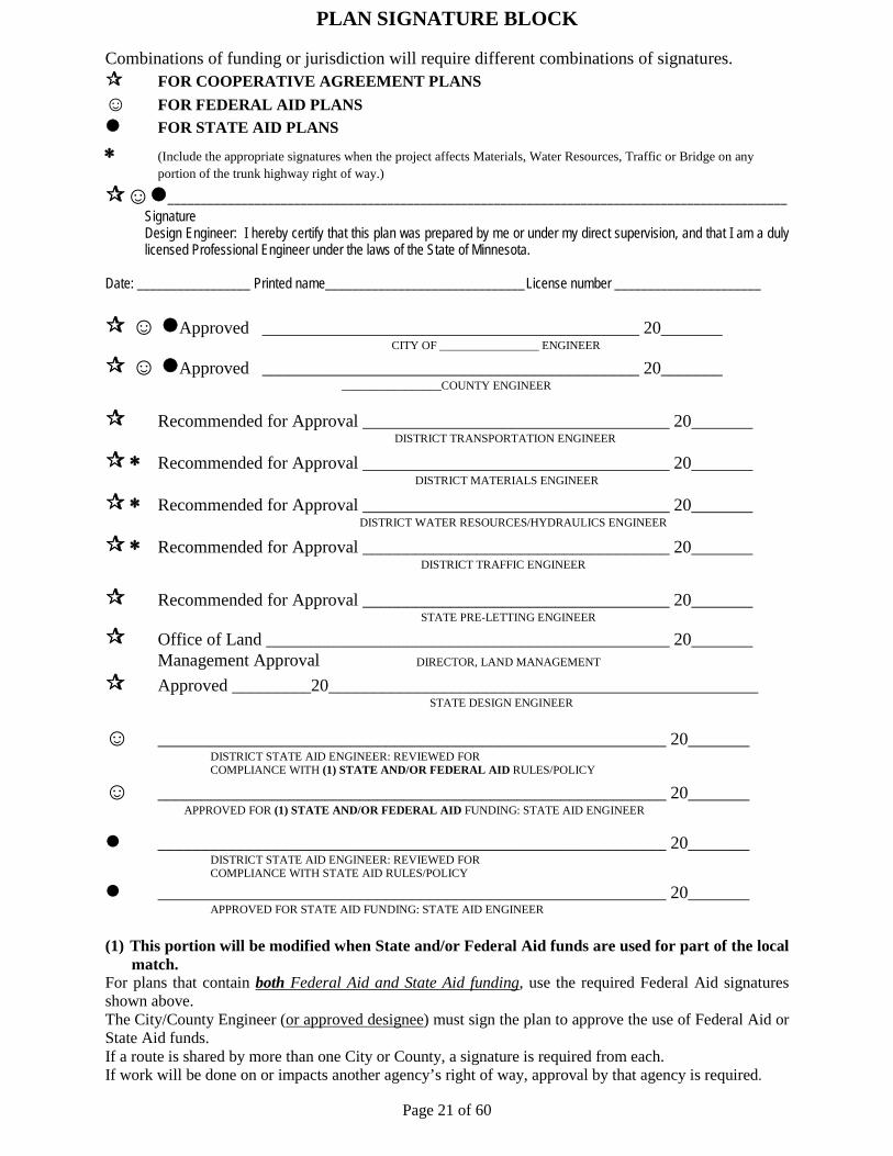
PLAN SIGNATURE BLOCK
Combinations of funding or jurisdiction will require different combinations of signatures. FOR COOPERATIVE AGREEMENT PLANS ☺ FOR FEDERAL AID PLANS FOR STATE AID PLANS
∗ (Include the appropriate signatures when the project affects Materials, Water Resources, Traffic or Bridge on any portion of the trunk highway right of way.)
☺_____________________________________________________________________________________________ Signature
Design Engineer: I hereby certify that this plan was prepared by me or under my direct supervision, and that I am a duly licensed Professional Engineer under the laws of the State of Minnesota.
Date: _________________ Printed name______________________________ License number ______________________ ☺ Approved ___________________________________________ 20_______
CITY OF _________________ ENGINEER
☺ Approved ___________________________________________ 20_______ _________________COUNTY ENGINEER
Recommended for Approval ___________________________________ 20_______ DISTRICT TRANSPORTATION ENGINEER
∗ Recommended for Approval ___________________________________ 20_______ DISTRICT MATERIALS ENGINEER
∗ Recommended for Approval ___________________________________ 20_______ DISTRICT WATER RESOURCES/HYDRAULICS ENGINEER
∗ Recommended for Approval ___________________________________ 20_______ DISTRICT TRAFFIC ENGINEER
Recommended for Approval ___________________________________ 20_______ STATE PRE-LETTING ENGINEER
Office of Land ______________________________________________ 20_______ Management Approval DIRECTOR, LAND MANAGEMENT
Approved _________20_________________________________________________ STATE DESIGN ENGINEER
☺ __________________________________________________________ 20_______ DISTRICT STATE AID ENGINEER: REVIEWED FOR COMPLIANCE WITH (1) STATE AND/OR FEDERAL AID RULES/POLICY
☺ __________________________________________________________ 20_______ APPROVED FOR (1) STATE AND/OR FEDERAL AID FUNDING: STATE AID ENGINEER
__________________________________________________________ 20_______ DISTRICT STATE AID ENGINEER: REVIEWED FOR COMPLIANCE WITH STATE AID RULES/POLICY
__________________________________________________________ 20_______ APPROVED FOR STATE AID FUNDING: STATE AID ENGINEER
(1) This portion will be modified when State and/or Federal Aid funds are used for part of the local match.
For plans that contain both Federal Aid and State Aid funding, use the required Federal Aid signatures shown above. The City/County Engineer (or approved designee) must sign the plan to approve the use of Federal Aid or State Aid funds. If a route is shared by more than one City or County, a signature is required from each. If work will be done on or impacts another agency’s right of way, approval by that agency is required.
Page 21 of 60

Page 22 of 60
STATE AID FUNDING ELIGIBILITY ITEM
ELIGIBILITY
CONDITIONS
FULL LIMITED Bike Paths
X
--MSA: in permanent R/W or parallel easement --CSA: part of bike path plan & in permanent R/W or parallel easement
Culverts
X
Curb & Gutter
X
--concrete or bituminous
Drain Tile
X
--as grading expense, not storm sewer
Engineering Costs: archaeological surveys pre-design design staking of right of way soils determination construction engineering inspection testing
MAX 25%
--Actual costs up to 25% of State Aid eligible construction costs
Landscaping:
MAX 5%
Max. 5% of yearly construction allocation
decorative handrails ornamental fences & railings brick pavers colored concrete aesthetic surface treatment special surface finish ornamental roadway lighting internally lit street signs
**
--decorative treatment on items necessary for transportation purposes --standard item costs paid for under grading ** costs in excess of standard item costs are eligible under 5% landscaping
trees
**
--when exceeding 2 to 1 replacement --no max dia.
shrubs, ground cover, mulch
**
irrigation
**
--when irrigating eligible landscaping on R/W
decorative retaining walls/planters
**
--when holding eligible items
decorative fences split rail
**
pedestrian lighting
**
--on R/W

Page 23 of 60
STATE AID FUNDING ELIGIBILITY ITEM
ELIGIBILITY
CONDITIONS
FULL LIMITED Lighting(roadway)--standard
X
--standard poles/fixtures (cobra,shoebox) --criteria: 1. 4 or more lanes, or 2. at intersection, or 3. revision due to reconstruction, or 4. within a city,or 5. approval of DSAE w/justification
Lighting(rdwy)--ornamental
X
**
--if required by adopted city/county policy ** if not--see landscaping
Mailbox Supports
X
Overlays
X
Pedestrian Ramps
X
Retaining Walls
X
Right-of-Way:
payment for land
X
--taken or damaged
payment for easements
X
--temporary or permanent
appraisal costs
X
--owners' & local road authority
owners/occ relocation costs
X
title searches
X
abstract update
X
--due to taking (costs necessary for property owner to clear title to make property merchantable are NOT eligible)
filing fees: recording of deed satisfaction of mortgage
X
state deed tax
X
condemnation costs
X
payment to utility company
X
--utility movement required by construction
cleanup of contaminated property
X
--reimbursement by owners/polluters to be paid back to State Aid account
Roundabouts
X
Same as “signal below”
Seal Coats
X
--no time limit
Seed/Sod/Mulch
X

Page 24 of 60
STATE AID FUNDING ELIGIBILITY ITEM
ELIGIBILITY
CONDITIONS
FULL LIMITED Sidewalks incl: bit/conc boulevard
X
--MSA or CSA, one or both sides --no width limit
Signals incl: EVP, Signs Eligibility Sketch: See Next Sheet
**
** if any legs eligible, all public streets under same jurisdiction eligible
Signal Interconnect
X
--either by legs or 100% on mainline
Storm Sewer See Tech Memo 96-SA-02
**
** proportionate share determined by State Aid Hydraulics Engineer
Surfacing
X
Signing/Striping
X
Trees
X
--2 to 1 replacement
Water/Sanitary Sewer
X
--only replacement due to construction --upgrades not eligible
ITEMS NOT ELIGIBLE Parking Meters, incl relocation Street signs on corners Work off State Aid R/W (unless approved by DSAE)

Page 25 of 60
SIGNAL FUNDING OPTIONS
8820.3100 GENERAL STATE-AID LIMITATIONS. Subp. 5. Traffic control signals. The extent of state-aid participation in signal installations must be determined by the proportion of the number of approaching routes under the jurisdiction of the county or urban municipality to the total number of approaching routes involved at each installation. When at least one approach is eligible for state-aid participation for a county or urban municipality, then all other approaches under the same jurisdiction are also eligible.
Approaches Funding Options 1 TH 1 MSAS (offsystem) 2 CSAH / or MSAS (offsystem) MSAS City Local 3 MSAS 3 4 4 City Local or MSAS CSAH 2 1 TH 1 MSAS (offsystem) 2 CSAH / or MSAS (offsystem) Co Rd City Local 3 County Local or CSAH 3 4 4 City Local or MSAS (offsystem) CSAH 2 1 TH 1 MSAS (offsystem) MSAS Private Rd 2 CSAH / or MSAS (offsystem) 3 4 3 MSAS CSAH 2 4 City Local or Private
Scenario 2
Scenario 1
Scenario 3

BRIDGE FUNDING ELIGIBILITY
• Federal Bridge Funds (FBF), designated “BR” in the State Transportation Improvement Program (STIP), are available for up to 80% of the “abutment to abutment” costs of eligible bridge rehabilitation or reconstruction work on any publicly owned bridge or culvert longer than 20 feet (clear span as measured along the roadway centerline). “Abutment to abutment” costs include the 2 foot granular fill or concrete slab above the top of a culvert and all materials under the fill or slab. Bridges to receive funds are selected by the Area Transportation Partnership (ATP). Federal Funds are provided “in part” are limited to federal funds indicated in the STIP. Funding is dependent on the availability of funds.
o Bridges, which are deficient under federal criteria and have a sufficiency rating less than 50 are eligible for reconstruction.
o Bridges, which are deficient under federal criteria and have a sufficiency rating less than 80 are eligible for rehabilitation.
o Bridges with sufficiency rating greater than 80 are not eligible for Federal Bridge Funds.
• Minnesota State Transportation Funds, State Bridge Bonding funds (SBB) aka “Fund 29” are available for up to 100% (typically 20% for matching FBF) of the “abutment to abutment” costs of eligible rehabilitation or reconstruction work on any publicly owned bridge or culvert longer than 10 feet (clear span as measured along the roadway centerline), or roadway in lieu of bridge work. Work must be done by contract, not local forces.
o Bridges, which are deficient under federal criteria and have sufficiency rating less than 80 are eligible for SBB.
o Roadway in lieu of bridge projects are eligible for SBB, up to the cost of replacing the structure; this includes structure removal, grading, and right-of-way.
o Bridges that replace structures less than 10 feet long are eligible for SBB. o Eligibility for Town Bridge Funds is the same as SBB.
• Items not eligible for FBF and SBB may be eligible for State Aid funding (SA) if on a State-Aid
route.
• Town Bridge (Twn Br) funds are available for up to 100% of eligible township bridge rehabilitation, reconstruction, or other necessary work. The County may request 100% funding if the cost is less than $20,000. Items eligible for bridge items is shown the Twn Br column. Approaching grading is eligible after the first $10,000 of local cost (including bridge removal), if requested in writing.
• Turnback funds may be used to replace or repair bridges the Trunk Highway turnback projects. Eligibility is the same as shown in the SA column.
• “Prorated” means the item is partially eligible at the ratio of participating to non-participating items. Traffic control and mobilization are two common examples.
• Decorative or aesthetic items are limited to the estimated cost of the standard items. For example, a chain link fence may be standard, but the designer feels a decorative railing is appropriate in particular situations. The proration rate is the estimated cost for chain link fence, divided by actual unit price of the decorative railing.

Page 27 of 60
BRIDGE FUNDING ELIGIBILITY
ITEM
ELIGIBILITY
CONDITIONS FBF TWN
BR
SBB SA
GENERAL
Mobilization X X X X
100% eligible if approach grading is to the touchdown point. Pro-rated by participating bridge amount if grading goes beyond touchdown point.
Structure Excavation X X X X
Engineering & Surveying X X X See Tech Memos 93-SA-05 for eligibility of historic/archaeological review services with federal planning funds.
Bridge and Non-Bridge Removals X X* X * See note (1) Approach Grading Cost.
Salvage X* X * See note (1) Approach Grading Cost.
Traffic control X X X X
100% eligible if approach grading is to the touchdown point. Pro-rated by participating bridge amount if grading goes beyond touchdown point.
Right of Way X* X* X *May be eligible on road-in-lieu of bridge projects.
Utility Work X X Whether electrical, gas, telephone not owned by subdivision of the State; or storm, sanitary owned by subdivision of the State.
BRIDGE STRUCTURES Granular Backfill for Abutment Drainage System System
X X X X
Granular Bedding X X X X
Bridge Foundation & Structure X X X X Includes piling, beams, joints, rebar, overlays,
bearings…
Slope Preparation & Paving X X X X

Page 28 of 60
BRIDGE FUNDING ELIGIBILITY
ITEM
ELIGIBILITY
CONDITIONS FBF TWN
BR
SBB SA
Concrete Sidewalk on Bridge X X(a) X(a) X
(a) If existing &/or if urban sidewalk approaching (up to 6’ both sides; 8’ if only one side). Remaining width may be eligible for FBF, SA, or FA funds; State Aid Manual 5.4.VI
Path on Bridge X X(b) X(b) X
(b) If existing &/or urban path approaching bridge (maximum 8’ if only on one side). See sidewalk funding conditions above if on both sides. Remaining width may be eligible for FBF, SA, or FA funds; State Aid Manual 5.4.VI
Drainage System X X X X On the bridge and/or behind abutments.
Lighting Systems (including conduit) X X X X If lighting is justified. Ornamental units
prorated to standards.
Guard Rail X X X X
Ornamental Metal Rail X X X X Prorated to cost of standard railing or chain link fence.
Architectural Surface Treatment X X Subject to 5% of annual construction
allocation cap. See “landscape” guidance.
CULVERTS
Culvert Pipe & Aprons X X X X
Culvert Bedding X X X X
Culvert Backfill Including Granular X X X X Eligible to minimum depth of cover required
(usually 2’).
APPROACH WORK
Clearing & Grubbing X X* X * See note (1) Approach Grading Cost.
Common Excavation for Approaches X X* X * See note (1) Approach Grading Cost.

Page 29 of 60
BRIDGE FUNDING ELIGIBILITY
ITEM
ELIGIBILITY
CONDITIONS FBF TWN
BR
SBB SA
Topsoil Borrow X X* X * See note (1) Approach Grading Cost.
Surfacing X X* X Concrete, bituminous or aggregate. * See note (1) Approach Grading Cost.
Curb & Gutter X X* X * See note (1) Approach Grading Cost.
Sidewalks Along Approaches X X* X * See note (1) Approach Grading Cost.
Channel Excavation X X X X To the touchdown point.
Approach Panels X X* X* X *Eligible if included in the same plan as the bridge construction.
EROSION CONTROL
Riprap X X X X Granular or geo filter incidental.
Silt Fence X X* X * See note (1) Approach Grading Cost.
Turf Establishment X X* X * See note (1) Approach Grading Cost.
OTHER
Water Retention Projects X X* X * See note (1) Approach Grading Cost. Needs to replace a deficient bridge.
(1) Approach grading costs are those costs for grading & surfacing the roadway approaches to the bridge, from the bridge to the point where an alignment that meets design standards can match into the existing alignment. Bridge removal is an approach grading cost. For Town Bridge Funds only, costs in excess of $10,000 are eligible.
Note this list represent the projects that commonly apply for bridge funds. If you have a project replacing a deficient bridge and would like more information on potential bridge funding, contact Patti Loken at 651-366-3803.

Page 30 of 60
LOW SPEED URBAN HORIZONTAL CURVE DESIGN CURVE RADII FOR VARIOUS DESIGN SPEEDS ON
LOW-SPEED URBAN STREETS WITH CURB AND GUTTER BASED ON MAXIMUM URBAN FRICTION FACTORS
RATE OF SUPER 20 MPH 25 MPH 30 MPH 35 MPH 40 MPH
(e)
-0.02 96 182 300 454 667 0.02 84 155 250 372 534 0.03 81 149 240 356 508 0.04 79 144 231 341 485 0.05 77 139 223 327 464 0.06 75 135 215 315 445
EQUATION FOR DETERMINING RADIUS
R = V² / [ 15 ( e + f ) ]
WHERE:
R = RADIUS (ft) AT CENTERLINE V = SPEED (mph) e = SUPER-ELEVATION f = URBAN FRICTION FACTOR
SUPER-ELEVATION SHALL BE DEVELOPED 2/3 ON TANGENT AND 1/3 ON CURVE.
SAVED AS FIG D-3 .221
SPEED FRICTION FACTOR (mph) (for e = 0.06)
20 0.30 25 0.25 30 0.22 35 0.20 40 0 18

Page 31 of 60
Rate of Superelevation and Calculated Length of Runoff for Rural and High-Speed Urban Roadways (emax = 0.06 ft/ft) (S = 0.0025 ft/ft)
DEGREE OF
CURVE (D)
RADIUS OF
CURVE (R)
V=40 mph V=45 mph V=50 mph V=55 mph V=60 mph V=65 mph V=70 mph V=75 mph
e L e L e L e L e L e L e L e L
0°15’ 22918 NC 0 NC 0 NC 0 NC 0 NC 0 NC 0 NC 0 NC 0
0°30’ 11459 NC 0 NC 0 NC 0 NC 0 NC 0 RC 96.0 RC 96.0 RC 96.0
0°45’ 7639 NC 0 NC 0 RC 96.0 RC 96.0 0.021 100.8 0.023 110.4 0.026 124.8 0.029 139.2
1°00’ 5730 NC 0 RC 96.0 RC 96.0 0.023 110.4 0.027 129.6 0.030 144.0 0.033 158.4 0.037 177.6
1°15’ 4584 RC 96.0 RC 96.0 0.024 115.2 0.028 134.4 0.032 153.6 0.036 172.8 0.040 192.0 0.044 211.2
1°30’ 3820 RC 96.0 0.024 115.2 0.028 134.4 0.032 153.6 0.037 177.6 0.041 196.8 0.046 220.8 0.051 244.8
1°45’ 3274 0.023 110.4 0.027 129.6 0.031 148.8 0.036 172.8 0.041 196.8 0.046 220.8 0.051 244.8 0.056 268.8
2°00’ 2865 0.025 120.0 0.030 144.0 0.035 168.0 0.040 192.0 0.045 216.0 0.049 235.2 0.055 264.0 0.059 283.2
2°15’ 2546 0.028 134.4 0.033 158.4 0.038 182.4 0.043 206.4 0.048 230.4 0.053 254.4 0.057 273.6 0.060 288.0
2°30’ 2292 0.030 144.0 0.035 168.0 0.040 192.0 0.045 216.0 0.051 244.8 0.055 264.0 0.059 283.2 Dmax=2°15’ 2°45’ 2083 0.032 153.6 0.037 177.6 0.042 201.6 0.048 230.4 0.053 254.4 0.058 278.4 0.060 288.0 3°00’ 1910 0.034 163.2 0.039 187.2 0.044 211.2 0.050 240.0 0.055 264.0 0.059 283.2 Dmax=2°45’ 3°15’ 1763 0.036 172.8 0.041 196.8 0.046 220.8 0.052 249.6 0.057 273.6 0.060 288.0
3°30’ 1637 0.038 182.4 0.043 206.4 0.048 230.4 0.054 259.2 0.058 278.4 Dmax=3°15’
3°45’ 1528 0.039 187.2 0.045 216.0 0.050 240.0 0.055 264.0 0.059 283.2 4°00’ 1432 0.041 196.8 0.046 220.8 0.051 244.8 0.057 273.6 0.060 288.0
4°15’ 1348 0.042 201.6 0.048 230.4 0.053 254.4 0.058 278.4 0.060 288.0 4°30’ 1273 0.043 206.4 0.049 235.2 0.054 259.2 0.059 283.2 Dmax=4°15’ 4°45’ 1206 0.044 211.2 0.050 240.0 0.055 264.0 0.059 283.2 5°00’ 1146 0.046 220.8 0.051 244.8 0.056 268.8 0.060 288.0 5°15’ 1091 0.047 225.6 0.053 254.4 0.057 273.6 0.060 288.0 5°30’ 1042 0.048 230.4 0.054 259.2 0.058 278.4 Dmax=5°15’ 5°45’ 996 0.049 235.2 0.055 264.0 0.059 283.2
KEY TO TABLE R = Radius of curve, ft Dmax = Maximum degree of curve V = Design speed, mph e = Superelevation rate, ft/ft NC = Normal Crown RC = Remove Crown
L = Calculated length of superelevation runoff, ft (From adverse crown removed to full superelevation, based on one lane of rotation. L value for RC condition based on normal 0.020 cross slope.)
NOTES: 1. emax = 0.06 ft/ft 1. Tangent runout lengths are in addition to the table runoff lengths 2. Table transition runoff lengths based on:
𝑳𝑳 = 𝑾𝑾 × 𝒆𝒆𝑺𝑺
Where: S = Longitudinal slope (MnDOT typical 𝟏𝟏𝟒𝟒𝟒𝟒𝟒𝟒
or 0.0025 ft/ft )
W = Lane width (12 ft) e = Superelevation (Table values based on method 5 procedures
of AASHTO where superelevation and side friction are in a curvilinear relation with the inverse of the radius of curve)
6°00’ 955 0.050 240.0 0.055 264.0 0.059 283.2
6°15’ 917 0.051 244.8 0.056 268.8 0.060 288.0
6°30’ 881 0.052 249.6 0.057 273.6 0.060 288.0
6°45’ 849 0.053 254.4 0.058 278.4 0.060 288.0
7°00’ 819 0.053 254.4 0.058 278.4 Dmax=6°45’ 7°15’ 790 0.054 259.2 0.059 283.2
7°30’ 764 0.055 264.0 0.059 283.2
7°45’ 739 0.055 264.0 0.059 283.2
8°00’ 716 0.056 268.8 0.060 288.0
8°15’ 694 0.057 273.6 0.060 288.0
8°30’ 674 0.057 273.6 0.060 288.0
8°45’ 655 0.058 278.4 Dmax=8°30’ 9°00’ 637 0.058 278.4 9°15’ 619 0.058 278.4 9°30’ 603 0.059 283.2 9°45’ 588 0.059 283.2
10°00’ 573 0.059 283.2
10°30’ 546 0.060 288.0 Where conditions are restrictive, the following absolute minimum longitudinal slopes may be used:
11°00’ 521 0.060 288.0
11°30’ 498 Dmax=11°15’ Design Speed 40 45 50 55 60 65 70
Slope 1:170 1:185 1:200 1:215 1:230 1:240 1 250

Page 32 of 60
Minimum Rates of Superelevation and Calculated Length of Runoff for Low-Speed Roadways in Urban Locations (emax = 0.06 ft/ft) (S = 0.0025 ft/ft)
RADIUS
OF CURVE
(R)
V=20 mph V=25 mph V=30 mph V=35 mph V=40 mph
e L e L e L e L e L
700 NC 0 NC 0 NC 0 NC 0 NC 0 600 NC 0 NC 0 NC 0 NC 0 RC 96.0 500 NC 0 NC 0 NC 0 NC 0 0.035 168.0 450 NC 0 NC 0 NC 0 RC 96.0 0.059 283.2 400 NC 0 NC 0 NC 0 RC 96.0 Rmin=450 375 NC 0 NC 0 NC 0 0.021 100.8 350 NC 0 NC 0 NC 0 0.036 172.8 325 NC 0 NC 0 NC 0 0.054 259.2 300 NC 0 NC 0 NC 0 Rmin=320
275 NC 0 NC 0 RC 96.0 250 NC 0 NC 0 RC 96.0 225 NC 0 NC 0 0.046 220.8 200 NC 0 NC 0 Rmin=215 175 NC 0 RC 96.0 150 NC 0 0.026 124.8
140 NC 0 0.046 220.8
130 NC 0 Rmin=135 125 NC 0 120 NC 0 KEY TO TABLE 115 NC 0 110 NC 0 R = Radius of curve, ft
Rmin = Minimum radius of curve, ft
105 NC 0 100 NC 0 V = Design speed, mph
95 RC 96.0 e = Superelevation rate, ft/ft NC = Normal Crown RC = Remove Crown L = Calculated length of superelevation runoff, ft
(From adverse crown removed to full superelevation, based on one lane of rotation. L value for RC condition based on normal 0.020 cross slope.)
90 RC 96.0 85 RC 96.0 80 0.033 158.4 75 0.056 268.8 Rmin=75
NOTES:
1. emax = 0.06 ft/ft 2. Tangent runout lengths are in addition to the table runoff lengths 3. Table transition runoff lengths based on:
L = W x e
S
Where: S = Longitudinal slope (Mn/DOT typical 1
400or 0.0025 ft/ft)
W = Lane width (12 ft) e = Superelevation rate (Table values based on method 2 procedures of AASHTO where first
side friction and then superelevation are increased in inverse proportion to the radius of curve)
Where conditions are restrictive, the following absolute minimum longitudinal slopes may be used: Design Speed 20 25 30 35 40 Slope 1:140 1:150 1:160 1:165 1:170

Page 33 of 60
Figure B(1) 5-892.211 Crest Vertical Curves October 22, 2004 Minimum Length of Vertical Curves of "Stopping Sight Distance"
V (mph)
A 25 30 35 40 45 50 55 60 65 70 75 80 0.8 75 90 105 120 135 150 165 180 195 210 225 240 L=3V 0.9 75 90 105 120 135 150 165 180 195 210 225 240 1 75 90 105 120 135 150 165 180 195 210 225 240
1.1 75 90 105 120 135 150 165 180 195 210 225 240 1.2 75 90 105 120 135 150 165 180 195 210 225 240 1.3 75 90 105 120 135 150 165 180 195 210 225 240 1.4 75 90 105 120 135 150 165 180 195 210 225 279 S>L 1.5 75 90 105 120 135 150 165 180 195 210 225 381 1.6 75 90 105 120 135 150 165 180 195 210 291 471 1.7 75 90 105 120 135 150 165 180 195 210 371 551 1.8 75 90 105 120 135 150 165 180 195 261 441 621 1.9 75 90 105 120 135 150 165 180 195 324 504 684 2 75 90 105 120 135 150 165 180 211 381 561 741
2.1 75 90 105 120 135 150 165 180 262 432 612 792 2.2 75 90 105 120 135 150 165 180 309 479 659 839 2.3 75 90 105 120 135 150 165 202 352 522 702 882 2.4 75 90 105 120 135 150 165 241 391 561 741 921 2.5 75 90 105 120 135 150 165 277 427 597 777 959 2.6 75 90 105 120 135 150 165 310 460 630 810 998 2.7 75 90 105 120 135 150 191 341 491 661 841 1036 S<L 2.8 75 90 105 120 135 150 219 369 519 689 872 1074 2.9 75 90 105 120 135 150 246 396 546 716 904 1113 3 75 90 105 120 135 150 271 421 571 741 935 1151
3.1 75 90 105 120 135 154 294 444 594 766 966 1190 3.2 75 90 105 120 135 176 316 466 616 790 997 1228 3.3 75 90 105 120 135 196 336 486 636 815 1028 1266 3.4 75 90 105 120 135 215 355 505 655 840 1059 1305 3.5 75 90 105 120 135 233 373 523 675 864 1091 1343 3.6 75 90 105 120 135 251 391 541 694 889 1122 1381 3.7 75 90 105 120 137 267 407 557 713 914 1153 1420 3.8 75 90 105 120 152 282 422 572 733 938 1184 1458 3.9 75 90 105 120 167 297 437 587 752 963 1215 1497 4 75 90 105 120 181 311 451 602 771 988 1246 1535
4.1 75 90 105 120 194 324 464 617 790 1012 1277 1573 4.2 75 90 105 120 206 336 476 632 810 1037 1309 1612 4.3 75 90 105 120 218 348 488 647 829 1062 1340 1650 4.4 75 90 105 120 230 360 500 662 848 1087 1371 1688 4.5 75 90 105 130 240 370 511 678 868 1111 1402 1727 4.6 75 90 105 141 251 381 522 693 887 1136 1433 1765 4.7 75 90 105 151 261 391 534 708 906 1161 1464 1804 4.8 75 90 105 160 270 400 545 723 925 1185 1496 1842 4.9 75 90 105 170 280 410 556 738 945 1210 1527 1880 5 75 90 105 178 288 418 568 753 964 1235 1558 1919
5.1 75 90 105 187 297 427 579 768 983 1259 1589 1957 5.2 75 90 105 195 305 435 590 783 1002 1284 1620 1995 5.3 75 90 105 203 313 444 602 798 1022 1309 1651 2034 5.4 75 90 105 210 320 452 613 813 1041 1333 1683 2072 5.5 75 90 108 218 328 460 624 828 1060 1358 1714 2111 5.6 75 90 115 225 335 469 636 843 1080 1383 1745 2149 5.7 75 90 121 231 341 477 647 858 1099 1408 1776 2187 5.8 75 90 128 238 348 485 659 873 1118 1432 1807 2226 5.9 75 90 134 244 354 494 670 888 1137 1457 1838 2264
Page 34 of 60
Figure B(1) 5-892.211 Crest Vertical Curves (Cont.) October 22, 2004 Minimum Length of Vertical Curves of "Stopping Sight Distance"
V (mph) A 25 30 35 40 45 50 55 60 65 70 75 80 6 75 90 140 250 360 502 681 903 1157 1482 1870 2302
6.1 75 90 146 256 366 511 693 918 1176 1506 1901 2341 6.2 75 90 152 262 372 519 704 933 1195 1531 1932 2379 6.3 75 90 157 267 378 527 715 949 1215 1556 1963 2418 6.4 75 90 163 273 384 536 727 964 1234 1580 1994 2456 6.5 75 90 168 278 390 544 738 979 1253 1605 2025 2494 6.6 75 90 173 283 396 552 749 994 1272 1630 2056 2533 6.7 75 90 178 288 402 561 761 1009 1292 1655 2088 2571 6.8 75 90 183 293 408 569 772 1024 1311 1679 2119 2609 6.9 75 90 187 297 414 578 783 1039 1330 1704 2150 2648 7 75 92 192 302 420 586 795 1054 1349 1729 2181 2686
7.1 75 96 196 306 426 594 806 1069 1369 1753 2212 2725 7.2 75 100 200 310 432 603 818 1084 1388 1778 2243 2763 7.3 75 104 204 315 438 611 829 1099 1407 1803 2275 2801 7.4 75 108 208 319 444 619 840 1114 1427 1827 2306 2840 7.5 75 112 212 323 450 628 852 1129 1446 1852 2337 2878 7.6 75 116 216 328 456 636 863 1144 1465 1877 2368 2916 7.7 75 120 220 332 462 644 874 1159 1484 1901 2399 2955 7.8 75 123 223 336 468 653 886 1174 1504 1926 2430 2993 7.9 75 127 227 341 474 661 897 1189 1523 1951 2462 3032 8 75 130 230 345 480 670 908 1204 1542 1976 2493 3070
8.1 75 134 234 349 486 678 920 1220 1562 2000 2524 3108 8.2 75 137 237 353 492 686 931 1235 1581 2025 2555 3147 8.3 75 140 240 358 498 695 942 1250 1600 2050 2586 3185 8.4 75 143 243 362 504 703 954 1265 1619 2074 2617 3223 8.5 75 146 246 366 510 711 965 1280 1639 2099 2648 3262 8.6 75 149 249 371 516 720 976 1295 1658 2124 2680 3300 8.7 75 152 252 375 522 728 988 1310 1677 2148 2711 3338 8.8 75 155 255 379 528 737 999 1325 1696 2173 2742 3377 8.9 75 158 258 384 534 745 1011 1340 1716 2198 2773 3415 9 75 160 261 388 541 753 1022 1355 1735 2222 2804 3454
9.1 75 163 264 392 547 762 1033 1370 1754 2247 2835 3492 9.2 75 165 266 397 553 770 1045 1385 1774 2272 2867 3530 9.3 78 168 269 401 559 778 1056 1400 1793 2297 2898 3569 9.4 80 170 272 405 565 787 1067 1415 1812 2321 2929 3607 9.5 83 173 275 410 571 795 1079 1430 1831 2346 2960 3645 9.6 85 175 278 414 577 804 1090 1445 1851 2371 2991 3684 9.7 88 178 281 418 583 812 1101 1460 1870 2395 3022 3722 9.8 90 180 284 422 589 820 1113 1475 1889 2420 3054 3761 9.9 92 182 287 427 595 829 1124 1491 1909 2445 3085 3799 10 94 184 290 431 601 837 1135 1506 1928 2469 3116 3837 K 12 19 29 44 61 84 114 151 193 247 312 384 S 155 200 250 305 360 425 495 570 645 730 820 910
V = Design Speed (mph) L minimum = 3V; desirable as per AASHTO S = Sight Distance (ft) L = Length of Curve (ft) When S > L; Then L = 2S - 2158/A A = Algebraic Difference of the Grades When S < L; Then L = (AS^2)/2158 Height of Eye = 3.5 feet
Height of Object = 2.0 feet When A > 10; Then L = AK
Note: S and K values given above and used in calculations are the rounded "design" values as given in Exhibit 3-76, pg 274 of AASHTO's "A Policy on Geometric Design of Highways and Streets, 2001".

Page 35 of 60
Figure B(2) 5-892.211 Sag Vertical Curves January 14, 2005
Minimum Length of Vertical Curves of "Stopping Sight Distance"
V (mph) A 25 30 35 40 45 50 55 60
0.8 75 90 105 120 135 150 165 180 L=3V 0.9 75 90 105 120 135 150 165 180 1 75 90 105 120 135 150 165 180
1.1 75 90 105 120 135 150 165 180 1.2 75 90 105 120 135 150 165 180 1.3 75 90 105 120 135 150 165 180 1.4 75 90 105 120 135 150 165 180 1.5 75 90 105 120 135 150 165 180 1.6 75 90 105 120 135 150 165 180 1.7 75 90 105 120 135 150 165 180 1.8 75 90 105 120 135 150 165 180 1.9 75 90 105 120 135 150 165 180 2 75 90 105 120 135 150 165 180
2.1 75 90 105 120 135 150 165 180 2.2 75 90 105 120 135 150 165 180 2.3 75 90 105 120 135 150 165 180 2.4 75 90 105 120 135 150 165 180 2.5 75 90 105 120 135 150 165 182 2.6 75 90 105 120 135 150 170 219 2.7 75 90 105 120 135 151 200 253 S>L 2.8 75 90 105 120 135 176 228 285 2.9 75 90 105 120 148 199 255 314 3 75 90 105 121 167 221 279 342
3.1 75 90 105 137 185 241 302 367 3.2 75 90 105 151 201 260 324 392 3.3 75 90 114 165 217 278 344 414 3.4 75 90 125 178 232 295 363 436 3.5 75 90 136 191 246 311 381 456 3.6 75 94 146 202 259 326 398 475 3.7 75 103 155 213 271 340 414 493 3.8 75 111 164 224 283 353 429 510 3.9 75 118 173 234 294 366 443 526 4 75 125 181 243 305 378 457 541
4.1 80 132 189 252 315 390 470 556 4.2 86 138 196 261 325 401 482 570 4.3 91 144 203 269 334 411 494 583 S<L 4.4 96 150 210 276 343 421 506 597 4.5 101 156 217 284 351 431 517 610 4.6 105 161 223 291 359 440 529 624 4.7 109 166 229 298 367 450 540 638 4.8 114 171 234 304 375 459 552 651 4.9 118 176 240 311 383 469 563 665 5 122 180 245 317 390 478 575 678
5.1 125 184 250 323 398 488 586 692 5.2 129 188 255 330 406 498 597 705 5.3 132 192 260 336 414 507 609 719 5.4 135 196 265 342 422 517 620 733 5.5 139 200 270 349 429 526 632 746 5.6 142 204 275 355 437 536 643 760 5.7 145 207 279 361 445 545 655 773 5.8 148 211 284 368 453 555 666 787 5.9 150 215 289 374 461 565 678 800 6 153 218 294 380 468 574 689 814
6.1 155 222 299 387 476 584 701 828 6.2 158 225 304 393 484 593 712 841 6.3 161 229 309 399 492 603 724 855

Page 36 of 60
Figure B(2) 5-892.211 Sag Vertical Curves (Cont.) January 14, 2005
Minimum Length of Vertical Curves of "Stopping Sight Distance"
V (mph) A 25 30 35 40 45 50 55 60
6.4 163 233 314 406 500 612 735 868 6.5 166 236 319 412 507 622 747 882 6.6 168 240 324 418 515 632 758 895 6.7 171 244 328 425 523 641 770 909 6.8 173 247 333 431 531 651 781 922 6.9 176 251 338 437 539 660 793 936 7 178 255 343 444 547 670 804 950
7.1 181 258 348 450 554 679 816 963 7.2 184 262 353 456 562 689 827 977 7.3 186 265 358 463 570 699 839 990 7.4 189 269 363 469 578 708 850 1004 7.5 191 273 368 475 586 718 862 1017 7.6 194 276 373 482 593 727 873 1031 7.7 196 280 377 488 601 737 885 1045 7.8 199 284 382 494 609 746 896 1058 7.9 201 287 387 501 617 756 908 1072 8 204 291 392 507 625 766 919 1085
8.1 206 295 397 513 632 775 931 1099 8.2 209 298 402 520 640 785 942 1112 8.3 212 302 407 526 648 794 954 1126 8.4 214 305 412 532 656 804 965 1140 8.5 217 309 417 539 664 813 977 1153 8.6 219 313 422 545 671 823 988 1167 8.7 222 316 426 551 679 833 1000 1180 8.8 224 320 431 558 687 842 1011 1194 8.9 227 324 436 564 695 852 1023 1207 9 229 327 441 571 703 861 1034 1221
9.1 232 331 446 577 710 871 1046 1234 9.2 235 335 451 583 718 880 1057 1248 9.3 237 338 456 590 726 890 1069 1262 9.4 240 342 461 596 734 900 1080 1275 9.5 242 345 466 602 742 909 1092 1289 9.6 245 349 471 609 749 919 1103 1302 9.7 247 353 475 615 757 928 1115 1316 9.8 250 356 480 621 765 938 1126 1329 9.9 252 360 485 628 773 947 1138 1343 10 255 364 490 634 781 957 1149 1357 K 26 37 49 64 79 96 115 136 S 155 200 250 305 360 425 495 570

VARIANCES
“Where a local unit of government feels that a variance from the Minnesota Rules for State Aid Operations Chapter 8820 is justified they shall submit a written request, in the form of a resolution, passed by the pertinent political subdivision, to the Commissioner of the Minnesota Department of Transportation. As required in State Aid Operations Rules, Chapter 8820.3300, the resolution shall identify the project by locale and termini, shall cite the specific rule or standard for which the variance is requested and describe the modification proposed.”
See the following page for a checklist to aid in formulating a variance request. Requests are due March 1, June 1, September 1, and December 1 of each year. The variance committee will then convene at the ends of those months to hear the requests.
Contact Metro State Aid (Dan Erickson or Julie Dresel) well in advance of the deadline to work through Variance issues. Final Request is due to Central Office as noted above. Submit variance requests to:
Please send a copy of the request to: Dan Erickson or Julie Dresel Metro State Aid 1500 W. County Road B2 Roseville, MN 55113
Page 37 of 60

Page 38 of 60
Variance Packet information The planning, scoping, design, implementation, operation, and maintenance of roads should reasonably address the safety and accessibility needs of users of all ages and abilities. The needs of motorists, pedestrians, transit users, and vehicles, bicyclists, and commercial and emergency vehicles moving along and across roads, intersections, and crossings should be consideration in a manner that is sensitive to the local context and recognizes the varying needs in urban, suburban, and rural settings. A request for a variance to the design elements required by State Aid Operations Rules Chapter 8820 should contain the following as applicable: 1. As required by the Rules: a certified resolution from the responsible city council or
county board which identifies the project by location and termini, cites the applicable Rule and chapter, cites the standard for which the variance is requested, and describes what is proposed in lieu of the standard. If applicable, cite the relevant guidance provided in the latest edition of “A Policy on Geometric Design of Highways and Streets”, from AASHTO. For projects in urban areas, if applicable, cite the relevant guidance provided in the latest edition of the “Context Sensitive Solutions in Designing Major Urban Thoroughfares for Walkable Communities” from the Institute of Transportation Engineers.
2. Location map and typical section (in-place and proposed).
3. Describe adjacent land uses (agricultural, residential, commercial, etc).
4. Describe the needs of motorists, pedestrians, transit users, and vehicles, bicyclists, and commercial and emergency vehicles moving along and across roads, intersections, and crossings should be consideration in a manner that is sensitive to the local context. If applicable, cite the relevant guidance provided in the Institute of Transportation Engineers’ “Context Sensitive Solutions in Designing Major Urban Thoroughfares for Walkable Communities“.
5. Describe effects of designing in accordance to Rule versus proposed non-standard element on adjacent properties, pedestrians, bicycles, motoring public, and emergency vehicles.
6. Define the critical design element involved (i.e. not "Design Speed"): horizontal alignment (radius or degree of curvature), vertical alignment, grades, lane width, shoulder width, bridge width, structural capacity, stopping sight distance (horizontal and vertical), cross slope, super-elevation, clearance (horizontal and vertical).

Page 39 of 60
Variance Packet information (cont.) 1. Estimate the cost/impacts to construct to the standard, the cost to build to the
proposed element, and information that logically explains why the particular proposed design was chosen. For instance, if the radius and sight distance for a horizontal curvature is proposed at 35 mph instead of 55 mph, include cost/impacts for 50 mph and 40 mph radii and sight distance.
2. Include available accident data in detail that indicates the resulting damage (property
damage/injury/death), contributing causes, and location. The Minnesota Crash Mapping Analysis Tool (MnCMAT) is available thru the SALT Traffic Safety website at: http://www.dot.state.mn.us/stateaid/trafficsafety.html. Note that access to the MnCMAT application requires approval of the city or county engineer. Questions on gaining access or use of the application can be directed to [email protected].
3. Include existing and projected traffic counts.
4. Include legal, posted, and/or safe speed of abutting roadway sections.
5. Indicate if future improvements are planned on the roadway or on adjacent property.
6. Describe safety mitigation considered, such as signing in accordance with MMUTCD, side-slope flattening, etc.
7. Any other pertinent factors.

Page 40 of 60
Landscape Items Metro State Aid Plan and Payment Policy
Plans
All plans should show a separate column for landscaping items. The “Statement of Estimated Quantities” should contain a separate column for landscape items. This column will contain all items that are considered to be decorative landscaping such as wildflowers, shrubs, waste receptacles, etc. By providing an extra landscaping column on the plans, both the Local Partner and Mn/DOT personnel will see the bottom line cost for landscaping at a glance. Items that are functional but ornamental, such as brick pavers, internally lit street signs, and ornamental fences and railings, will fall into both the roadway and landscaping columns. These items are eligible under the roadway column up to the cost of the average bid price for an equivalent non-ornamental item. The excess cost of these items is considered to be landscaping and will be subject to the 5% annual landscaping reimbursement cap per State Aid Rules 8820.3100, Subpart 10. To split these items between two columns, State Aid and the Local Partner should develop a mutually agreeable percentage which will reflect what portion of the cost is the state aid eligible roadway cost and what portion is the excess cost for the ornamental product. This percentage will then be applied to the quantity for the item and shown in the roadway and landscaping columns as a quantity, reflecting the percentage split. For example, brick pavers for sidewalks are eligible up to the usual cost of a regular concrete sidewalk. The excess cost of the pavers over regular concrete is considered a landscape expense and is eligible within the 5% landscaping cap. If the agreed upon percentage for this item was 80% roadway and 20% landscaping (the cost of the pavers was 20% more than the cost of regular concrete sidewalk) the Statement of Estimated Quantities would be shown like this: S.A.P. 123-456-789 Item No. Description Unit Total Estimated
Quantity Roadway
Landscaping
2531.604 Brick Pavers SF 1000 800 200

Page 41 of 60
Reimbursement
Landscape expenditures will be capped at 5% of the annual construction allocation based on the calendar year of the submittal and the actual payment made to the local partner. The purpose of using the calendar year versus the plan approval year is to simplify the record keeping system, to more efficiently and equitably track expenditures, and to allow the most flexibility for our customers. For purposes of expenditure tracking, the 5% retainage on landscaping items will be considered payable during the year of finalization, when the local partner actually receives the money, not during the year of the original submittal. The reason for this is to better manage overrun/underrun issues. We need to ensure that the actual dollar amount being spent on landscaping does not exceed the 5% cap for any given calendar year and that the local partner is allowed to fully utilize landscaping funds despite overruns or underruns.
Tracking Procedure
1. When a Report of State Aid Contract is received for a project which contains landscaping items, a copy of that local partner’s current year construction allocation will be obtained and the 5% landscaping cap will be computed.
2. The Landscaping Items paid out on the report (95%) will then be deducted from the
Landscaping cap. 3. As the calendar year progresses, all other reports from the same local partner will have any
landscaping items deducted from the landscape cap until a zero balance is achieved. 4. If a local partner expends their entire landscaping allotment, they will be advised that they
can choose one of the following options: shift the remaining costs into a non-participating status; temporarily shift the landscaping items into non-participating status until the time of final estimate when a new allocation may be available; submit partial requests in subsequent years to recover 100% of the landscaping costs.
5. At the time of the Report of Final Estimate, landscaping costs will be reconciled with
previous payments and the 5% retainage and overrun payments will be deducted from the current year’s landscaping cap.
Page 42 of 60
SIGNAL JUSTIFICATION REPORT (SJR) WHEN REQUIRED? - NEW SIGNAL INSTALLATION (TEMPORARY OR PERMANENT) - COMPLETE RECONSTRUCTION OF EXISTING SIGNAL (Changes affecting number of lanes, relocation of poles, etc.)
WARRANT ANALYSIS WHEN REQUIRED? - REVISION TO EXISTING SIGNAL (Adding signal heads, pedestrian heads, phasing changes, etc.) - ADDITION OF EMERGENCY VEHICLE PRE-EMPTION (EVP)
WHEN ARE NEITHER REQUIRED? - REPLACEMENT OF LOOPS DUE TO MILLING (ANY APPROACHES) - OTHER ROADWAY CONSTRUCTION NOT AFFECTING THE
APPEARANCE OR OPERATION OF THE SIGNAL SYSTEM. NOTE: IF SIGNAL ON Mn/DOT R/W (TRUNK HIGHWAY,
INTERSTATE, RAMPS, FRONTAGE ROADS), CONTACT LARS IMPOLA (651-234-7820) FOR MN/DOT REQUIREMENTS.
Process for SJR Approval on “State Aid Projects” YES
NO CITY, COUNTY OR CONSULTANT Note: Signal Agreements Take 1-3 months to process
All signed SJRs are returned to the submitting Agency.
State Aid Signal Justification Reports Prepared by: City, County &
METRO DISTRICT STATE AID
Assist State Aid Engr. Julie Dresel (Signature)
Impact to a Trunk Highway?
METRO TRAFFIC ENGINEERING SECTION
Traffic Studies – Lars Impola reviews and distributes for internal review to:
Program Support Area Coordinator Signal Agreements
Who comment then forward when ready for signature to:
Studies Engineer – Brad Estochean (Signature)
Lars Impola then returns signed SJR to State Aid
METRO DIVISION STATE AID
Julie Dresel

Page 44 of 60
SIGNAL JUSTIFICATION REPORT CONTENTS
WHAT IS REQUIRED?
- TITLE/SIGNATURE PAGE **see attached example**
- INDEX MAP
- INTERSECTION LAYOUT
Existing & Proposed conditions Show All lanes of approach on all legs of the intersection - PROJECT DESCRIPTION **see attachment for items needed** - WARRANT ANALYSIS SHEET & WARRANT SUMMARY ** see attached examples** - JUSTIFICATION STATEMENT - APPENDIX (Data from studies as appropriate): Traffic Count Data 24 or 48 hour vehicle traffic volumes and/or 12 hour turning count 3 hour AM & PM Peak Vehicle Turning Movement Count Pedestrian Count Accident History Study/Collision Diagram Pedestrian Gap Study Delay Study Heavy Vehicle Survey Projected Traffic Volumes Approach Travel Speeds Other pertinent information (i.e.: letters) **EACH PROPOSED INSTALLATION SHOULD HAVE A SEPARATE SJR

Page 45 of 60
(Title/Signature Page)
SIGNAL JUSTIFICATION REPORT FOR
Roadway Name
AT
Roadway Name
CITY OR COUNTY OF
S.A.P. ____ - ____ - ____
I hereby certify that this report was prepared by me or under my direct supervision and that I am
a duly Licensed Professional Engineer under the laws of the State of Minnesota. ______________________________________________ _________________ ___________ Name Reg. No. Date APPROVED: ______________________________________________________ ___________ City of / or ___ County Engineer Date APPROVED: ______________________________________________________ ___________ Metro District – State Aid Engineer Date (if a Trunk Highway is part of the signalized intersection, include the following) APPROVED: _____________________________________________________ ____________ Metro District – Traffic Engineer Date

Page 46 of 60
PROJECT DESCRIPTION
This should be a general description of the existing conditions and the proposed project. the idea is to give the reader as thorough a picture of the intersection and project as possible. The following is a list of information that should be presented: 1. INTERSECTION LOCATION Major & Minor streets City & County City population Project Numbers 2. CHARACTER OF THE SITE Function & Importance of the roads Number of lanes Existing & proposed geometrics channelization, grades, parking, speed limits, sight distances, etc. Land use: traffic generators, future development Existing traffic control Adjacent signals Proposed coordination 3. TYPE OF WORK Signal or beacon Temporary or permanent (if temporary, proposed date of removal) Phasing Scope of project—part of larger project? 4. TIME SCHEDULE Proposed letting date Anticipated construction date 5. ESTIMATED PROJECT COST Type of funding Distribution of cost Maintenance responsibilities Who will operate

Page 47 of 60
JUSTIFICATION STATEMENT This section is an explanation of why the signal is being installed. Traffic signals are not installed because they meet a warrant, but because engineering judgment has determined that they are needed and justified. Why is this signal needed? NOTE: Warrants should be viewed as guidelines, not as hard and fast values. Satisfaction of a warrant is not a guarantee that the signal is really needed. Conversely, the fact that a warrant is not fully satisfied does not constitute absolute assurance that signalization would not serve a useful purpose. The application of warrants is effective only when combined with knowledgeable engineering judgment and awareness of local conditions. Engineering judgment must be exercised to assure that the traffic signal will not increase the hazard or cause unnecessary delay to the public. This section should state what studies were conducted, conclusions reached, and the engineering judgment used. It should also state any city, county and citizen concerns that would affect the decision; where did the concern for this intersection originate. Who wants the signal? NOTE: An intersection must meet a signal warrant in order for the traffic signal installation to be eligible for State Aid funding. Advance Warning Flashers will need to be justified in this section, if installation is proposed. The criteria set forth in the Technical Memorandum No. 86-22-T-7 “Guidelines for the Installation of Advanced Warning Flashers to Alert Motorists to Traffic Signal Change Intervals” must be met. Include the study and analysis in the appendix.
Page 48 of 60
WARRANT SUMMARY (Required)
______________________________ at__________________________________ This traffic control signal meets the following MMUTCD warrants: Warrant No. 1 – Eight Hour Vehicular Volume met for _____ hours
Condition A-Minimum Vehicular Volume met for _____ hours
Condition B-Interruption of Continuous Traffic met for _____ hours Warrant No. 2 – Four Hour Vehicular Volume met for _____ hours Warrant No. 3 – Peak Hour met for _____ hours Warrant No. 4 – Pedestrian Volume met for _____ hours Warrant No. 5 – School Crossing (met) (does not meet) Warrant No. 6 – Coordinated Signal System (met) (does not meet) Warrant No. 7 – Crash Experience (met) (does not meet) Warrant No. 8 – Roadway Network (met) (does not meet) Note: All background supporting data for met warrants is included in the Appendix of this report. This flashing beacon meets the following Mn/DOT warrants: Warrant No. 1 – Limited Visibility (met) (does not meet) Warrant No. 2 – Accident Rate (met) (does not meet) Warrant No. 3 – School Crossing (met) (does not meet) Warrant No. 4 – Rural Trunk Highway Junctions (met) (does not meet) Note: All background supporting data for met warrants is included in the Appendix of this report.

Page 49 of 60
ROUNDABOUT JUSTIFICATION REPORT (RJR)
Here are some elements to consider when choosing a roundabout. This information was taken from NCHRP Report 672 Roundabout Guide. A roundabout feasibility study report may include the following elements:
• Identify why a roundabout is being considered as an improvement alternative at this intersection.
• Identify the current status of traffic operations and safety at the intersection for comparison with expected roundabout performance.
• Identify a conceptual roundabout configuration, which includes the number of lanes on each approach and the designation of those lanes.
• Demonstrate whether an appropriately sized and configured roundabout can be implemented feasibly.
• Identify all potential complicating factors, assess their relevance to the location, and identify any mitigation efforts that might be required.
Where more complete or formal rationale is necessary, the roundabout feasibility study report may also include the following additional considerations:
• Demonstrate institutional and community support, indicating that key institutions (e.g. police, fire department, and schools) and key community leaders have been consulted.
• Give detailed performance comparisons (including delay, capacity, emissions, and/or interaction effects with nearby intersections) of the roundabout with alternative control modes.
• Include an economic analysis indicating that a roundabout compares favorably with alternative control modes from a benefit-cost perspective.
• Include a detailed discussion about potential trade-offs between safety, operations, and design.
• Include detailed appendices containing traffic volume data, signal or all-way stop-control warrant analysis, and so on.
RJR’s are similar to ICE reports process so here is a link for ICE process: http://www.dot.state.mn.us/trafficeng/safety/ice/index.html
*RJR requirements are still being discussed and will include more information as it becomes available
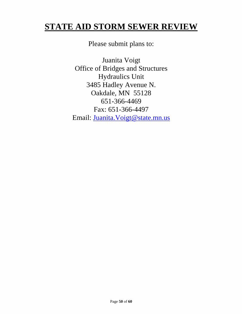
Page 50 of 60
STATE AID STORM SEWER REVIEW
Please submit plans to:
Juanita Voigt Office of Bridges and Structures
Hydraulics Unit 3485 Hadley Avenue N.
Oakdale, MN 55128 651-366-4469
Fax: 651-366-4497 Email: [email protected]

Page 51 of 60
STORM SEWER SUBMITTAL INFORMATION
Plans will be submitted for Hydraulic review when the project consists of any of the following:
• A mainline pipe is being replaced or a new system is being installed. • There is work proposed on catch basins and leads (jobs that consist entirely of catch basins and leads will be 100% eligible for State Aid funding). • When an outlet pipe to an existing or proposed State Aid storm sewer.
If a Hydraulic review is needed, the following should be submitted:
• A drainage area map showing land use and an area to each inlet. • Drainage calculations Storm sewer computations, including pipe sizing, grades and invert
elevations Drainage structure data, including design type, size, invert elevations
and type of casting assembly Hydraulic design data, i.e. frequency event, time of concentration, etc.
• Catch basin spread computations Run by, depth at gutter line and width of spread on pavement
(reference the State Aid Manual Table A 5-892.605) • Plan Sheets Title sheet, showing job limits, ADT & design speed. Estimate, with participating storm sewer items in a separate column. Typical Sections with right of way limits, lane and shoulder widths,
and slopes shown. Drainage tabulations, notes and details (if other than Standard Plates). Sewer profiles with pipe sizes, lengths, grades and inverts, structure
locations, types and elevations, and existing and proposed utilities. Plan view showing proposed and existing sewer lines and pipe
lengths, sizes and grades. • Engineer’s Estimate

Page 52 of 60
PAVEMENT DESIGN
The use of R-values as a basis for pavement design is encouraged in the State Aid Manual because it provides a more economical and appropriate pavement design structure. This method should be used for the design of all 10-ton pavements. The Mn/DOT Geotechnical and Pavement Manual provides information for using this method of pavement design, along with information on computing the ESAL Factor to be used in conjunction with the R-value. The following tables are taken from the Geotechnical Manual to aid you in your design. Table 4-4.2. Vehicle classification volumes. Revised February 1, 1997
VEHICLE CLASS PERCENT OF AADT Analysis of 1983-1989 Data
Vehicle Classes
Trunk Highways Greater Minnesota
Trunk Highways Mpls/St. Paul Seven County Area
Rural CSAH or County Road
Average Min/Max 95% of data sites
Average Min/Max 95% of data sites
Average
Autos, pickups 89 93 94.1 2 ax, 6 tire SU 2.7 .4 / 9.3 < 4.9 2.2 .8 / 7.6 < 3.6 2.6 3 + ax SU 1.5 0 / 28.7 < 4.1 1.0 0 / 8.9 < 2.8 1.7 3 ax TST .1 0 / 1.1 < .3 .2 0 / 1.2 < .4 0.0 4 ax TST .2 0 / 1.6 < .6 .2 0 / 1.1 < .6 0.1 5 + ax TST 6.1 0 / 31.0 < 15.5 3.2 0 / 22.6 < 10.6 0.5 Buses, Trucks w/Trailers .4 0 / 3.9 < 1.2 .3 0 / 2.7 < .9 1.0 Twin Trailers .1 0 / 1.0 < .3 .0 0 / .4 < .2 0.0
Total Number of Sites N = 837 N = 239 1977 County Road Study
SU = Single Unit Trucks TST = Tractor Semi-Trailer ax = axle

Page 53 of 60
4-4.0(8) PAVEMENT MANUAL July 4, 2007 Table 4-4.3. Average ESAL factors by vehicle classification from WIM. Revised February 1, 1997
Flexible ESAL Factors for the Design-Lane TH 99 I-494 I-94 TH 2 I-94
Vehicle Class Default a b c d MNROAD Cars, Pick-ups .0007 c 2 ax 6 tire SU .25 .26 .13 .22 .26 .25 **3+ ax SU .58 .51 .63 .44 .71 .61
3 ax TST .39 .26 .21 .55 .36 .59 4 ax TST .51 .57 .35 .47 .50 .60 5+ax TST 1.13 .92 1.14 1.00 1.74 .99
*(6 ax TST) .78 .42 .74 .64 .69 .69 T w/tr, buses .57
MTC buses 1.25
Twin Trailers 2.40 .49 .77 2.16 1.90 3.15
Rigid ESAL factors for the Design-Lane
Cars, Pick-ups .0007 a b c d c 2 ax 6 tire SU .24 .25 .12 .21 .25 .24 **3+ ax SU .84 .73 .93 .62 1.09 .90
3 ax TST .37 .25 .20 .53 .34 .56 4 ax TST .53 .60 .35 .49 .52 .63 5+ax TST 1.89 1.52 1.90 1.66 2.94 1.64
*(6 ax TST) .80 .51 .89 .77 .83 .83 T w/tr, buses .74
MTC buses 1.23
Twin Trailers 2.32 .47 .73 2.09 1.84 3.06 Vehicle Classes: Data Taken From Years: SU = Single Unit Trucks a = 1985, 1990 TST - Tractor Semi-trailer b = 1982-1985, 1990 ax = axle c = 1990 WIM = Weighing-in-Motion (fixed sites) d = 1984, 1985, 19 T w/tr = Trucks with trailers MTC = Urban transit buses * - This vehicle class is not usually considered separately in an ESAL forecast. **- Use 0.91 if the route is a sugar beet hauling route.

Page 54 of 60
4-4.0(10) PAVEMENT MANUAL July 4, 2007 Table 4-4.4. Sample ESAL calculation. Revised February 1, 1997
Example 20-Year Design Lane Cumulative ESAL Calculation (Use only if you do not have access to the MNESALS electronic spreadsheet)
Vehicle Classes
Base Flexible Base Design Design Year ESAL Year Year Year ADL AADT Factors ADL AADT (Two- (Two- Way) Way)
Cars and Pick-ups 1207 x .0007 = .8 1690 1.2 2 ax, 6 tire SU 98 x .25 = 24.5 137 34.2 3 + ax SU 34 x .58 = 19.7 48 27.8 3 ax TST 6 x .39 = 2.3 8 3.1 4 ax TST 8 x .51 = 4.1 11 5.6 5 + ax TST 120 x 1.13 = 135.6 168 189.8 Buses, Trucks w/Trailers 25 x .57 = 14.2 35 20 Twin Trailers 2 x 2.40 = 4.8 3 7.2
TOTAL 1500 206 2100 288.9
ADL = Average Daily Load
(Base Year ADL + Design Year ADL) / 2 = (206 + 288.9) / 2 = 247 (rounded) Number of days in 20 years x 247 = 7300 x 247 = 1,804,335 Design Lane Factor (if 4 lane) x 1,804,335 = .45 x 1,804,335 = 811,951 Load limit increase factor x 811,951 = 1.12 x 811,951 = 909,385 Cumulative 20-Year Design Lane Flexible ESAL (rounded) = 909,000 Procedures for calculating a cumulative 20-year Design Lane Rigid ESAL are the same as above except rigid ESAL factors are used in place of the flexible ESAL factors.

Page 55 of 60
Figure 5-3.7. Bituminous Pavement Design Chart (Aggregate Base).

ULTIMATE 10 TON STAGED FLEXIBLE PAVEMENT DESIGN USING SOIL FACTORS 1,5 Required Gravel Equivalency (G.E. in inches) for various Soil Factors (S.F.)
For new construction or reconstruction use projected ADT or HCADT; for reconditioning projects use present ADT or HCADT Designs shown here are for an initial 9 Ton pavement structure. Agencies can add pavement structure to increase to 10 Tons in the future
9 TON Staged : < 150 HCADT 9 TON Staged: 151 to 300 HCADT TYPE OF MATERIAL3 SPECIFICATION G.E.
FACTOR
Minimum Total Minimum Tota
l Bituminous Pavement 2360 2.25 S.F
. Bit G.E. G.E. S.F
. Bit G.E. G.E. Cold-Inplace Recycling (CIR) 2331 1.5
50 7 10.3
6 50 7 14 Rubblized Concrete 2231 1.5 75 7 13.9 75 7 17.5 Full Depth Reclamation 2331 1
100 7 17.5 100 7 21 Aggregate Base class 5 & 6 3138 1 110 7 19 110 7 22.4 Aggregate Sub-Base class 3 & 4 3138 0.75 120 7 20.5 120 7 23.8 Select Granular Mat’l 3149.2B2 0.5
130 7 22 130 7 25.2 AASHTO SOIL
FACTOR ASSUME
D GENERAL 4
9 TON Staged: 301 to 600
HCADT 9 TON Staged: 601 to 1100
HCADT SOIL CLASS (S.F.) R-VALUE PLASTICITY
Minimum Total Minimum Tota
l A - 1 50 - 75 70 - 75 NP S.F
. Bit G.E. G.E. S.F
. Bit G.E. G.E. A - 2 50 - 75 30 - 70 SP 50 7 16 50 8 18.5 A - 3 50 70 NP 75 7 20.5 75 8 23.7 A - 4 100 - 130 20 SP
100 7 25 100 8 29 A-5 130+ na na 110 7 26.8 110 8 31.1 A - 6 100 12 P 120 7 28.6 120 8 33.2 A - 7 - 5 120 12 P 130 7 30.4 130 8 35.3 A - 7 - 6 130 8 P
9 TON Staged: 1101 to 1500 HCADT2 Minimum Total S.F
. Bit G. E. G.E. 50 8 20.3 75 8 26.4
100 8 32.5 110 8 35 120 8 37.4 130 8 39.8
Values may not be exact due to rounding 1For 10 Ton design see page 31 in Mn/DOT Pavement Manual, July 2007, Chapter 5, Section 3, Figure 5-3-7. Bituminous Pavement Design Chart (Aggregate Base) 2For HCADT over 1500 more advanced design procedures should be used; please contact Mn/DOT's Pavement Design Unit 3See page 32 in Mn/DOT Pavement Manual, July 2007, Chapter 5, Section 3, Table 5-3.4 - Granular Equivalent (G.E.) factors 4General Plasticity: NP = nonplastic; SP= semi-plastic; P = plastic; na = not applicable (An A-5 soil rarely occurs in Minnesota) 5 Safety edge (30° to 35° wedge) are recommended to minimize edge dropoff. See www.dot.state.mn.us/stateaid/sa_safety_edge.html 6 These GE values are for the finished pavement section. During construction additional GE may be warranted for a construction platform. Origin - 1/10/201

Page 57 of 60
SPECIAL PROVISIONS Here is the link for MnDOT Special Provisions where you can download
the latest version of Provision for you project. http://www.dot.state.mn.us/pre-letting/prov/index.html
Traffic Management Plan (TMP)
http://www.dot.state.mn.us/metro/trafficeng/control_striping.html
BIKEWAY DESIGN
For Bikeway design please refer to State Aid Rule for On Road and Off Road Bikeway facilities.
For additional design guidelines refer to the MnDOT Bikeway Design
Guide. http://www.dot.state.mn.us/bike/design-engineering.html

Page 58 of 60
.6XX Transport List Extensions For items that are not on the Transport List please use a similar item number and a .6XX extension according to the correct unit of measure. Refer to the list below for measurement extensions.
English Metric .601 Lump Sum Lump Sum .602 Each Each .603 Lin Ft m .604 Sq Yd m2 .605 Acre ha .606 Gallon Lump Sum .607 Cu Yd m3 .608 Pound kg .609 Ton t .610 Hour Hour .611 Day Day .612 Week Week .613 Unit Day Unit Day .614 Structure Structure .615 Assembly Assembly .616 System System .617 Sq Ft/Day m2 /Day .618 Sq Ft .619 Road Sta .620 Yard .621 Dollar Dollar .622 MBM (Thousand Board Feet) .623 MGAL (M Gallons)

Page 59 of 60
General Redline Comments Observed on Plan General Comments: If there is Storm Sewer on a plan, please make sure to include an additional copy of the
plan along with Drainage map & calculations for eligibility review. If a roadway intersects with a Trunk Highway, please give me a heads up as these
reviews take longer and I will let you know if I need extra copies or a pdf of the plan for routing to the functional groups. The number of copies varies depending on the work proposed.
o Typically a copy is required for: State Aid Review Hydraulics Bridge Unusual Retaining Wall Designs
If there is a Signal or Signal revisions a SJR or SJL is required. o SJR is required when new signals or geometric changes are made to the
intersection o SJL are for modifications, upgrade to Left Turn Flashing Arrow or Flasher
Roundabouts require a RJR Sometimes a letter of explanation with the final plan submission is helpful to know what
changes were made or why something might not have been made. If a new person submitting to State Aid, please make sure to include your Name, Phone
number and email address. On State Aid Check list, please fill in the Rule you are using and do not put “See Table”
as I might pick the wrong rule which causes confusion when reviewing the plan and will make my review incomplete until the rule is called out.
If using MnDOT Lab Services, please submit a hard or electronic copy of the provisions. If multiple Agencies on a project and State Aid funds being utilized by one Agency other
than lead Agency, then Lead Agency needs to pull a State Aid Project number for tracking purposes.
Title Sheet: Specs must be switched over to 2016 at this point for submitted projects, no more 2005 or
2014 Specs. A County/City signature is required if work within County/City R/W limits. If there is a Trail on a project, make sure to include Trail Design Designation block.
Estimate Quantities/Tabulations: No decimals unless quantity is less than 1 or the following items: Drainage Structure
heights, sign panel, acres, tons, & Lump Sum splits. No 0 Zero quantities in SEQ or Tabs. For State Aid projects, items should be in order according to the Transport list (sequential
according to XXXX.XXX/XXXXX). If Project that go through MnDOT Central Office Review item must be in order according to Transport list.

Page 60 of 60
General Redline Comments Observed on Plan Cont. Estimate Quantities/Tabulations Cont.:
Check Transport items #’s and descriptions as some have changed from 2014 to 2016 Spec Book.
If there are Landscaping items, they must be in a separate Landscape column on the SEQ.
Salvage items must be reinstalled on the project to be eligible for State Aid funds. Standard Plates: In the description please include number of sheets for plate (X sheets). Check MnDOT website for latest plate version. FHWA Approval note is missing.
Standard Plans: There are new Erosion standard plans are out that for current Spec Book. ADA Standard Plans make sure you have the latest approval date. ADA Standard Plans sheets you must include all 5 sheets in the plan. Do not call out ADA Standard Plans 5-297.250 in the plan; they must be included in the
plan sheets. Please make sure to check MnDOT’s website to make sure you have the newest version
for a Standard Plan sheet as new versions are now available.
Typicals: When you draw a typical, make sure to label and dimension lanes, shoulders, parking,
curb reaction, trails, trail clear zones. Try not to give a var. label for dimensions giving dimension range is preferred for
verification purposes.
Plan Sheets:
Make sure to include Begin and End of State Aid Project limits on all plans sheets including stationing.