2013 baja car rear suspension redesign - uc drc home
TRANSCRIPT

2013 Baja Car Rear Suspension Redesign
A Baccalaureate thesis submitted to the
Department of Mechanical and Materials Engineering College of Engineering and Applied Science
University of Cincinnati
in partial fulfillment of the requirements for the degree of
Bachelor of Science
in Mechanical Engineering Technology
by
Sahil Patel
September 2014
Thesis Advisor:
Dean Allen Arthur
ii
ACKNOWLEDGMENTS
I would like to thank Dean Allen Arthur for his ongoing support, patience, and guidance
throughout this project. I would also like to thank Mr. Ronald Hudepohl, Mr. Douglas Rife,
Mr. David Conrad, and Mr. Bill Hansel for their assistance with the production and
assembly. This project would not be able to have been completed without them.

iii
TABLE OF CONTENTS
ACKNOWLEDGMENTS ........................................................................................................ II
TABLE OF CONTENTS ........................................................................................................ III
LIST OF FIGURES ............................................................................................................. IVV
ABSTRACT ............................................................................................................................. V
INTRODUCTION .................................................................................................................... 1
PROBLEM STATEMENT........................................................................................................................................ 1 INTERVIEWS ....................................................................................................................................................... 1
CUSTOMER REQUIREMENTS ............................................................................................. 2
PROOF OF DESIGN ................................................................................................................ 3
PREVIOUS DESIGN ............................................................................................................... 4
RESEARCH .............................................................................................................................. 5
DESIGN PROCESS.................................................................................................................. 8
REFERENCES ....................................................................................................................... 11
APPENDIX A - MANUFACTURING AND ASSEMBLY .................................................. 12
APPENDIX B - BUDGET...................................................................................................... 17
APPENDIX C - QUALITY CONTROL ................................................................................ 18
iv
LIST OF FIGURES
Figure 1 – List of Customer Requirements……………………………………………………2
Figure 2 – Figure 2 – Proof of Design ….…………………………………………………….3
Figure 3 – Previous Linkage Mounting Points ……………………………………………….4
Figure 4 – Double A-Arm Suspension………………………………………………………...5
Figure 5 – MacPherson Strut Suspension……………………………………………………..6
Figure 6 – Multi-Link Suspension…………………………………………………………….7
Figure 7 – Motion Sketch of Rear Side Wheel ……………………………………………….8
Figure 8 – Motion Sketch of Camber Change…………………………………………….......9
Figure 9 – Table with New Mounting Points………………………………………………….9
Figure 10 – 3D Final Model………………………………………………………………….10
Figure 11 – Dynamic Mass in Rear Axle…………………………………………………….10
Figure 12 – von Mises Stress Analysis………………………………………………………11
Figure 13 – Bottom Mounting Bracket………………………………………………………12
Figure 14 – Top Mounting Bracket………………………………………………………….13
Figure 15 – Bottom Link……………………………………………………………………..14
Figure 16 – Top Link………………………………………………………………………...15
Figure 17 – Bung Fitting……………………………………………………………………..16
Figure 18 – PVC Pipes……………………………………………………………………….18

v
ABSTRACT
The Society of Automotive Engineers (SAE) hosts a yearly intercollegiate Baja race at
various locations throughout the nation. Every college that chooses to compete in this event
assembles a team of undergraduate and / or graduate students to compete. This competition
will include competitions such as acceleration, hill climb, land maneuverability, suspension
and endurance. I will work on the redesign of the rear suspension that will be safe, reliable,
cost effective, and easy to maintain. The suspension redesign will be my senior design
project.

2013 Baja Car Rear Suspension Redesign Sahil Patel
1
INTRODUCTION
PROBLEM STATEMENT
Design an improved rear suspension in the 2013 UC Baja Car. The previous rear
suspension design of the 2013 Baja Car has an understeer causing poor handling. The new
design of the rear suspension must have a roll center of the rear suspension that is closer to
the current center of gravity which is 24”.
The relationship between the roll center and the center of gravity creates a moment on
the vehicle in turns. The greater the distance between the roll center and the center of gravity
the greater the moment the vehicle must overcome (2).
INTERVIEWS
Ricardo Hinojosa was a former Bearcats Baja member, class of 2013. He is
knowledgeable on the 2013 car due to his experience from building the car. He has expressed
his desire to reduce the understeer on the car. According to him, the geometry of the linkages
doesn’t match the suspension. This bit of information was important in developing my
problem statement revolving around the roll center of the vehicle.
Joe Kobs was the former president of the Bearcats Baja team in the year 2014. He
helped with the manufacturing of the 2013 as a 4th year Mechanical Engineering Technology
student. He stated that the 2013 car also has a problem with understeering. According to him
reliability of the suspension is imperative from his previous experience with the team. It was
critical to him that I have a design that will be able to withstand the maximum forces during
competition.

2013 Baja Car Rear Suspension Redesign Sahil Patel
2
CUSTOMER REQUIREMENTS
There are two primary customers for this project. The first is the Society of Automotive
Engineers (SAE). Every year SAE host an intercollegiate Baja Competition at 3 various
locations throughout America. These completions consist of 4 dynamic events; acceleration
hill climb, maneuverability, and rock crawl/suspension. On a yearly basis they issue rules and
regulations at which a vehicle must adhere to.
The second customer will be the University of Cincinnati Bearcats Baja team. They will
be using this car for future competitions and also for practice purposes.
The following are the requirements that have been determined.
1. Safety
The vehicle must be safe to operate.
Vehicle must adhere to SAE Baja rules.
2. Reliable
Must support person 200 lbs. weight in seat.
The design must be able to last in a SAE Baja race.
The camber angle must change less than 5° in the travel motion.
The travel motion of the rear wheels must at least be within the shock limit of
+4.00 inches and -0.50 inches vertically.
3. Easily maintained
Quick disconnects for the assembly parts.
Must be independent.
Can be maintained by using standard tools.
Minimal fabrication will done
The left and right side must mirror each other
4. Cost
Must stay within the allotted budget
Figure 1 – List of Customer Requirements

2013 Baja Car Rear Suspension Redesign Sahil Patel
3
PROOF OF DESIGN
Proof of design will be conducted by performing a test of the travel motion of the newly
designed linkages. The travel motion must be willing to travel up from resting position a
minimum distance of 4.25 inches. The distance of 4.25 inches is the distance determined by
the range of movement in the shock shown in figure 7.
Figure 2 – Proof of Design
2013 Baja Car Rear Suspension Redesign Sahil Patel
4
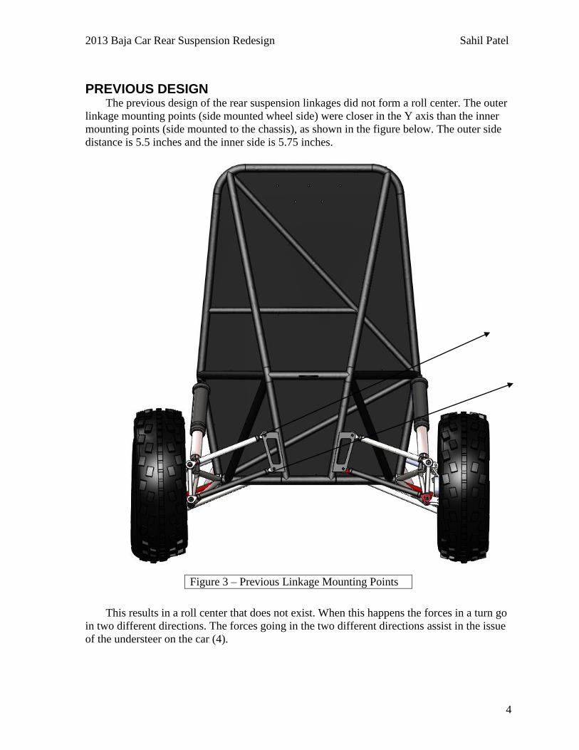
PREVIOUS DESIGN The previous design of the rear suspension linkages did not form a roll center. The outer
linkage mounting points (side mounted wheel side) were closer in the Y axis than the inner
mounting points (side mounted to the chassis), as shown in the figure below. The outer side
distance is 5.5 inches and the inner side is 5.75 inches. This results in a roll center that does not exist. When this happens the forces in a turn go
in two different directions. The forces going in the two different directions assist in the issue
of the understeer on the car (4).
Figure 3 – Previous Linkage Mounting Points

2013 Baja Car Rear Suspension Redesign Sahil Patel
5
RESEARCH
Figure 4 – Double A-Arm Suspension
Double A-Arm Suspension
This type of suspension is also referred to as the double wishbone. It
utilizes a dual “A” shaped arm. The two arms are on the same
horizontal plane and have a shock absorber running through the
arms. The top arm will be shorter than the bottom arm (4). Each arm
is has two mounting points connected to the frame and one joint at
the knuckle. This type of system is good for increasing negative
camber angle. In turn there are great traction qualities for turns. The
camber of the tire is also easily adjustable in this type of suspension.
(4)
This system is heavier
and takes up more
space than the
counterparts. This
suspension is
complex and has
multiple parts
associated with it.
The costs associated
with this particular
suspension are higher
than the counterparts.
Any maintenance for
the double A will be
time consuming.

2013 Baja Car Rear Suspension Redesign Sahil Patel
6
MacPherson Strut Suspension
The MacPherson Strut system is very common for modern day cars.
The shock absorber will be mounted vertically to the wheel hub. A
control arm will mounted from the frame to the wheel hub for some
additional support (1). This is a simple design with low maintenance
required. There is less room taken up by the suspension than the
double A arm and in turn this is a lighter option. This will help with
the car’s acceleration due to the fact that there will be less weight to
carry. This is the most economical of the three mentioned
suspensions.
(4)
It is difficult to
maintain traction
while cornering. This
is not a good design
for lowered vehicles.
The camber is set and
not easily adjustable.
This type of
suspension will have
trouble moving
horizontally.
Figure 5 – MacPherson Strut Suspension

2013 Baja Car Rear Suspension Redesign Sahil Patel
7
Figure 6 – Multi-Link Suspension
Multi-Link Suspension
This type suspension is a cousin of the double A suspension. The
multi-link suspension uses three or more lateral arms and one or
more longitudinal arms. There is a spherical joint at each end of the
connecting arms. The shock absorbers can mount to the longitudinal
arms if desired or mounted elsewhere if that is a more desirable
option. This allows for more flex for the vehicle which makes it
great for off road applications(3). This suspension is a happy
medium in terms of space in between the MacPherson and double A.
(4)
This can get to be
expensive to build.
The design of this
suspension is the
most complex of the
three types
mentioned. This type
of suspension
absolutely must be
finely tuned and if
there are any
deviations from the
plan, it can cause
damage to the vehicle
and possibly driver.
The car currently has
a multi-link
suspension, re-
designing the
linkages would be the
most cost-effective
plan moving forward.

2013 Baja Car Rear Suspension Redesign Sahil Patel
8
DESIGN PROCESS
The very first thing to be determined in the designing of linkages is the appropriate
travel motion of the rear wheels. Figure 7 is a motion sketch of the side view of the rear side
of the vehicle.
Adjusting the axis shown above shows the compression of the shock. When the car is
motionless on the ground the shock is compressed at 0.25 inches. When the shock is in full
compression it is 4.25 shorter meaning the travel needs to be +4.00 inches and -0.25 inches.
The second thing to consider in the design process was the change in camber while the
Figure 7 – Motion Sketch of Rear Side Wheel
Axis
Shock
4.00 inches
0.25 inches

2013 Baja Car Rear Suspension Redesign Sahil Patel
9
wheels move up and down. The optimum camber change rate I was looking for was ± 5°.
This was done by creating another motion sketch (Figure 8).
By moving the wheels up and down the camber of the wheel can be measured as well as
determining the optimal mounting points for the new linkages. The new changes in the
mounting points and camber change were recorded in a table (Figure 9). This table was
paramount in finding the best combination of roll center, new mounting points, and camber
change.
Figure 8 – Motion Sketch of Camber Change
Figure 9 – Table with New Mounting Points
CG
Roll Center

2013 Baja Car Rear Suspension Redesign Sahil Patel
10
The only issue with this method of design was the length of the linkages was only
considered in the X and Y direction. The total length of the linkage was determined via 3D
modeling which is shown in figure 10.
The final step in the design process was the Finite Element Analysis (FEA). The FEA
was conducted using SolidWorks software. The benefit of FEA is that I will allow me to
know where the possible failure would lie. The equation below in figure 11 shows the
dynamic mass in the rear axle.
Figure 10 – 3D Final Model
Figure 11 – Dynamic Mass in Rear Axle
2013 Baja Car Rear Suspension Redesign Sahil Patel
11
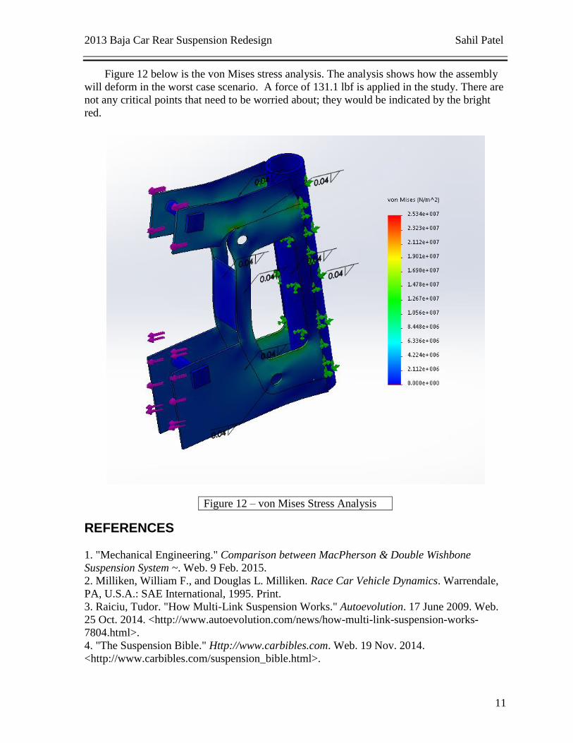
Figure 12 below is the von Mises stress analysis. The analysis shows how the assembly
will deform in the worst case scenario. A force of 131.1 lbf is applied in the study. There are
not any critical points that need to be worried about; they would be indicated by the bright
red.
REFERENCES
1. "Mechanical Engineering." Comparison between MacPherson & Double Wishbone
Suspension System ~. Web. 9 Feb. 2015.
2. Milliken, William F., and Douglas L. Milliken. Race Car Vehicle Dynamics. Warrendale,
PA, U.S.A.: SAE International, 1995. Print.
3. Raiciu, Tudor. "How Multi-Link Suspension Works." Autoevolution. 17 June 2009. Web.
25 Oct. 2014. <http://www.autoevolution.com/news/how-multi-link-suspension-works-
7804.html>.
4. "The Suspension Bible." Http://www.carbibles.com. Web. 19 Nov. 2014.
<http://www.carbibles.com/suspension_bible.html>.
Figure 12 – von Mises Stress Analysis

2013 Baja Car Rear Suspension Redesign Sahil Patel
12
APPENDIX A- MANUFACTURING AND ASSEMBLY
BRACKETS
Figure 13 – Bottom Mounting Bracket

2013 Baja Car Rear Suspension Redesign Sahil Patel
13
Both brackets were made via profile milling.
The brackets were the MIG welded to the frame tab.
Figure 14 – Top Mounting Bracket

2013 Baja Car Rear Suspension Redesign Sahil Patel
14
LINKAGE ASSEMBLY
Figure 15 – Bottom Link

2013 Baja Car Rear Suspension Redesign Sahil Patel
15
Bung fittings MIG welded to aluminum tubing cut to desired length for both top and
bottom links.
Each link has a left and right hand thread at opposite ends to allow for camber
control.
3/8” bolts and nuts were used to mount the linkages to the car.
Figure 16 – Bottom Link

2013 Baja Car Rear Suspension Redesign Sahil Patel
16
The bung fittings were cut to 1” pieces.
Lathe turned to a diameter of 0.675” at 0.50” length.
Figure 17 – Bung Fitting

2013 Baja Car Rear Suspension Redesign Sahil Patel
17
APPENDIX B- BUDGET
Build of Materials
Item Size Quantity Price
Heims
Joints
4 Left Hand
Thread
4 Right Hand
Thread
8 $75.84
AISI 4130
Steel Plate
12” X 12”
.08” Thick 2 $45.12
Aluminum
6061
Piping
72”
1" DIA x
0.125" THK
x 0.75"
1 $38.67
Aluminum
6061
Billet
12”
1” Diameter 1 $9.29
Total with Shipping ($32.09) $201.01

2013 Baja Car Rear Suspension Redesign Sahil Patel
18
APPENDIX C- QUALITY CONTROL
PVC replicas of the tubing lengths were created and fitted to ensure the tubing was
modeled correctly in SolidWorks
Figure 18 – PVC Pipes