yzfr3f · 2015. 7. 2. · 2ms-f1668-30 la pression des pneus a trol doit froid dit normalement...
TRANSCRIPT

arefully before operating this vehicle.
OWNER’S MANUAL
Read this
manual cDIC183
YZFR3F2MS-F8199-70
[English (E)]

EAU46091
Read this manual carefully before operating this vehicle. This manual should stay with this vehicle if it is sold.
U2MS70E0.book Page 1 Thursday, December 18, 2014 1:46 PM

INTRODUCTION
EAU45931
Congratulations on your purchase of the Yamaha YZFR3F. This model is the result of Yamaha’s vast experience in the pro-duction of fine sporting, touring, and pacesetting racing machines. It represents the high degree of craftsmanship and re-liability that have made Yamaha a leader in these fields.This manual will give you an understanding of the operation, inspection, and basic maintenance of this motorcycle. If youhave any questions concerning the operation or maintenance of your motorcycle, please consult a Yamaha dealer.The design and manufacture of this Yamaha motorcycle fully comply with the emissions standards for clean air applicableat the date of manufacture. Yamaha has met these standards without reducing the performance or economy of operationof the motorcycle. To maintain these high standards, it is important that you and your Yamaha dealer pay close attentionto the recommended maintenance schedules and operating instructions contained within this manual.Yamaha continually seeks advancements in product design and quality. Therefore, while this manual contains the most cur-rent product information available at the time of printing, there may be minor discrepancies between your motorcycle andthis manual. If there is any question concerning this manual, please consult a Yamaha dealer.
WARNING
EWA10022
Please read this manual carefully and completely before operating this motorcycle. Do not attempt to operate this
motorcycle until you have attained adequate knowledge of its controls and operating features and until you have
been trained in safe and proper riding techniques. Regular inspections and careful maintenance, along with good
riding skills, will ensure that you safely enjoy the capabilities and the reliability of this motorcycle.
U2MS70E0.book Page 1 Thursday, December 18, 2014 1:46 PM

IM
EAU10134
Pa ions:
*P
to potential personal injury ymbol to avoid possible injury
if not avoided, could result in
e taken to avoid damage to the
ier or clearer.
N
T
U2MS70E0.book Page 1 Thursday, December 18, 2014 1:46 PM
PORTANT MANUAL INFORMATION
rticularly important information is distinguished in this manual by the following notat
roduct and specifications are subject to change without notice.
This is the safety alert symbol. It is used to alert youhazards. Obey all safety messages that follow this sor death.
A WARNING indicates a hazardous situation which,death or serious injury.
A NOTICE indicates special precautions that must bvehicle or other property.
A TIP provides key information to make procedures eas
WARNING
OTICE
IP

IMPORTANT MANUAL INFORMATION
EAUN0430
YZFR3FOWNER’S MANUAL
©2014 PT Yamaha Indonesia Motor Manufacturing
1st edition, December 2014
All rights reserved.Any reprinting or unauthorized use without the written permission of
PT Yamaha Indonesia Motor Manufac-turing
is expressly prohibited.Printed in Indonesia.
U2MS70E0.book Page 2 Monday, December 1, 2014 11:39 AM

alve clearance............................. 7-16ires .............................................. 7-16ast wheels .................................. 7-18djusting the clutch lever free play..................................... 7-18hecking the brake lever free play..................................... 7-20rake light switches ..................... 7-20hecking the front and rear brake pads ................................ 7-21hecking the brake fluid level ...... 7-21hanging the brake fluid .............. 7-23rive chain slack........................... 7-23leaning and lubricating the drive chain................................. 7-25hecking and lubricating the cables........................................ 7-25hecking and lubricating the throttle grip and cable ............... 7-26hecking and lubricating the brake and shift pedals............... 7-26hecking and lubricating the brake and clutch levers ............. 7-27hecking and lubricating the sidestand................................... 7-27
ubricating the swingarm pivots......................................... 7-28hecking the front fork................. 7-28hecking the steering................... 7-29hecking the wheel bearings ....... 7-29attery .......................................... 7-29
U2MS70E0.book Page 1 Thursday, December 18, 2014 1:46 PM
TA
LO
LA
SA
DE
LRC
INS
FU
MI
MHCSBBFFF
CSHSR
BLE OF CONTENTS
CATION OF IMPORTANT
BELS ............................................. 1-1
FETY INFORMATION .................. 2-1
SCRIPTION .................................. 3-1eft view ......................................... 3-1ight view....................................... 3-2ontrols and instruments ............... 3-3
TRUMENT AND CONTROL
NCTIONS ...................................... 4-1ain switch/steering lock............... 4-1
ndicator lights and warning lights............................................ 4-2ulti-function meter unit ................ 4-4andlebar switches...................... 4-10lutch lever .................................. 4-11hift pedal .................................... 4-12rake lever.................................... 4-12rake pedal .................................. 4-12uel tank cap................................ 4-13uel............................................... 4-13uel tank breather hose and overflow hose............................ 4-15atalytic converter ....................... 4-15eats ............................................ 4-16elmet holders ............................. 4-17torage compartment .................. 4-18ear view mirrors.......................... 4-18
Adjusting the shock absorber assembly....................................4-18
Luggage strap holders ..................4-19Sidestand ......................................4-19Ignition circuit cut-off system .......4-20
FOR YOUR SAFETY –
PRE-OPERATION CHECKS .............5-1
OPERATION AND IMPORTANT
RIDING POINTS ................................6-1Starting the engine..........................6-1Shifting ............................................6-2Engine break-in ...............................6-4Parking ............................................6-4
PERIODIC MAINTENANCE AND
ADJUSTMENT...................................7-1Owner’s tool kit ...............................7-2........................................................7-3Periodic maintenance chart for
the emission control system........7-4General maintenance and
lubrication chart...........................7-5Checking the spark plugs ...............7-9Engine oil and oil filter cartridge....7-10Coolant..........................................7-13Replacing the air filter element
and cleaning the check hose.....7-14Checking the throttle grip free
play ............................................7-16
VTCA
C
BC
CCDC
C
C
C
C
C
L
CCCB

BLE OF CONTENTS
M
S
S
C
IN
U2MS70E0.book Page 2 Thursday, December 18, 2014 1:46 PM
TA
Replacing the fuses.......................7-31Replacing a headlight bulb............7-32Auxiliary light bulb .........................7-33Tail/brake light...............................7-34Replacing a turn signal light
bulb ............................................7-34Replacing the license plate
light bulb ....................................7-35Supporting the motorcycle............7-36Front wheel....................................7-36Rear wheel.....................................7-37Troubleshooting ............................7-39Troubleshooting charts .................7-41
OTORCYCLE CARE AND
TORAGE ..........................................8-1Matte color caution .........................8-1Care.................................................8-1Storage............................................8-4
PECIFICATIONS..............................9-1
ONSUMER INFORMATION ..........10-1Identification numbers...................10-1Maintenance record ......................10-3YAMAHA MOTOR CANADA
LTD. MOTORCYCLE WARRANTY GUIDE ...................10-5
DEX...............................................11-1
L
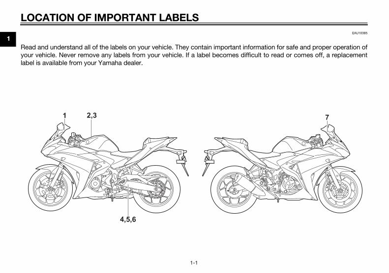
1EAU10385
Re ion for safe and proper operation ofyo read or comes off, a replacementlab
7
U2MS70E0.book Page 1 Thursday, December 18, 2014 1:46 PM
OCATION OF IMPORTANT LABELS
1-1
ad and understand all of the labels on your vehicle. They contain important informatur vehicle. Never remove any labels from your vehicle. If a label becomes difficult toel is available from your Yamaha dealer.
1 2,3
4,5,6
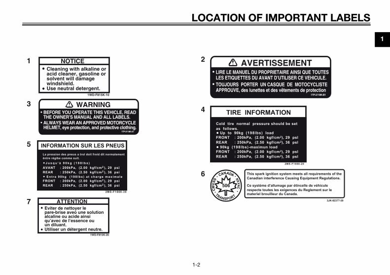
MPORTANT LABELS
1
PRIETAIRE AINSI QUE TOUTESNT D’UTILISER CE VEHICULE.
ISSEMENT
CASQUE DE MOTOCYCLISTEt des vêtements de protection
1TP-2118K-B1
ATION
2MS-F1668-20
e should be set
kgf/cm2), 29 pslkgf/cm2), 36 psl
oad
kgf/cm2), 29 pslkgf/cm2), 36 psl
load
gnition system meets all requirements of theterference Causing Equipment Regulations.
d’allumage par étincelle de véhiculetes les exigences du Reglement sur leuilleur du Canada.
3JK-82377-20
U2MS70E0.book Page 2 Thursday, December 18, 2014 1:46 PM
LOCATION OF I
1-2
NOTICECleaning with alkaline oracid cleaner, gasoline orsolvent will damagewindshield.Use neutral detergent.
1WD-F815K-10
ATTENTIONEviter de nettoyer lepare-brise aveo une solutionalcaline ou acide ainsiqu’avec de l’essence ouun diluant.Utiliser un détergent neutre.
1WD-F815K-20
BEFORE YOU OPERATE THIS VEHICLE, READTHE OWNER’S MANUAL AND ALL LABELS.
WARNING
ALWAYS WEAR AN APPROVED MOTORCYCLEHELMET, eye protection, and protective clothing.
1TP-2118K-A1
LIRE LE MANUEL DU PROLES ETIQUETTES DU AVA
AVERT
TOUJOURS PORTER UN APPROUVE, des lunettes e
INFORMATION SUR LES PNEUS
2MS-F1668-30
La pression des pneus a trol doit froid dit normalementêntre régibe comme suit.
AVANT : 200kPa, (2.00 kgf/cm2 ), 29 psiREAR : 250kPa, (2.50 kgf/cm2 ), 36 psi
J u s q u ’ à 9 0 k g ( 1 9 8 l b s )
FRONT : 200kPa, (2.00 kgf/cm2 ), 29 psiREAR : 250kPa, (2.50 kgf/cm2 ), 36 psi
E n t r a 9 0 k g ( 1 9 8 l b s ) a t c h a r g e m a x i m a l e
1 2
3
5
7
4
6
TIRE INFORMCold tire normal pressuras follows.
FRONT : 200kPa, (2.00 REAR : 250kPa, (2.50
Up to 90kg (198lbs) l
FRONT : 200kPa, (2.00 REAR : 250kPa, (2.50
90kg (198lbs)-maximun
This spark iCanadian in
Ce systémerespecte toumateriel broTRANSPORT
506

2
pears to be very effective in reduc-ing the chance of this type ofaccident.Therefore:
• Wear a brightly colored jacket.• Use extra caution when you are
approaching and passingthrough intersections, since in-tersections are the most likelyplaces for motorcycle accidentsto occur.
• Ride where other motorists cansee you. Avoid riding in anothermotorist’s blind spot.
• Never maintain a motorcyclewithout proper knowledge.Contact an authorized motorcy-cle dealer to inform you on ba-sic motorcycle maintenance.Certain maintenance can onlybe carried out by certified staff.
U2MS70E0.book Page 1 Thursday, December 18, 2014 1:46 PM
Be
AsspoatioMoThpetectheknoforHe
2-1
SAFETY INFORMATION
EAU1028B
a Responsible Owner
the vehicle’s owner, you are re-nsible for the safe and proper oper-n of your motorcycle.torcycles are single-track vehicles.
eir safe use and operation are de-ndent upon the use of proper ridinghniques as well as the expertise of operator. Every operator shouldw the following requirements be-
e riding this motorcycle. or she should:
Obtain thorough instructions froma competent source on all aspectsof motorcycle operation.Observe the warnings and mainte-nance requirements in this Own-er’s Manual.Obtain qualified training in safeand proper riding techniques.Obtain professional technical ser-vice as indicated in this Owner’sManual and/or when made neces-sary by mechanical conditions.
Never operate a motorcycle with-out proper training or instruction.Take a training course. Beginnersshould receive training from a cer-tified instructor. Contact an autho-rized motorcycle dealer to find outabout the training courses nearestyou.
Safe Riding
Perform the pre-operation checkseach time you use the vehicle to makesure it is in safe operating condition.Failure to inspect or maintain the vehi-cle properly increases the possibility ofan accident or equipment damage.See page 5-1 for a list of pre-operationchecks. This motorcycle is designed to
carry the operator and a passen-ger.
The failure of motorists to detectand recognize motorcycles in traf-fic is the predominating cause ofautomobile/motorcycle accidents.Many accidents have beencaused by an automobile driverwho did not see the motorcycle.Making yourself conspicuous ap-

FETY INFORMATION
2
otective Apparel
e majority of fatalities from motorcy- accidents are the result of head in-ies. The use of a safety helmet is thegle most critical factor in the pre-tion or reduction of head injuries.Always wear an approved helmet.Wear a face shield or goggles.Wind in your unprotected eyescould contribute to an impairmentof vision that could delay seeing ahazard.The use of a jacket, heavy boots,trousers, gloves, etc., is effectivein preventing or reducing abra-sions or lacerations.Never wear loose-fitting clothes,otherwise they could catch on thecontrol levers, footrests, or wheelsand cause injury or an accident.Always wear protective clothingthat covers your legs, ankles, andfeet. The engine or exhaust sys-tem become very hot during or af-ter operation and can causeburns.A passenger should also observethe above precautions.
U2MS70E0.book Page 2 Thursday, December 18, 2014 1:46 PM
SA
2-2
Many accidents involve inexperi-enced operators. In fact, many op-erators who have been involved inaccidents do not even have a cur-rent motorcycle license.• Make sure that you are qualified
and that you only lend your mo-torcycle to other qualified oper-ators.
• Know your skills and limits.Staying within your limits mayhelp you to avoid an accident.
• We recommend that you prac-tice riding your motorcyclewhere there is no traffic until youhave become thoroughly famil-iar with the motorcycle and all ofits controls.
Many accidents have beencaused by error of the motorcycleoperator. A typical error made bythe operator is veering wide on aturn due to excessive speed or un-dercornering (insufficient lean an-gle for the speed).• Always obey the speed limit and
never travel faster than warrant-ed by road and traffic condi-tions.
• Always signal before turning orchanging lanes. Make sure thatother motorists can see you.
The posture of the operator andpassenger is important for propercontrol.• The operator should keep both
hands on the handlebar andboth feet on the operator foot-rests during operation to main-tain control of the motorcycle.
• The passenger should alwayshold onto the operator, the seatstrap or grab bar, if equipped,with both hands and keep bothfeet on the passenger footrests.Never carry a passenger unlesshe or she can firmly place bothfeet on the passenger footrests.
Never ride under the influence ofalcohol or other drugs.
This motorcycle is designed foron-road use only. It is not suitablefor off-road use.
Pr
Thclejursinven

2
Av
AlmcaaccoCalesprancaanunlevfovesysofreM
en loading within this weight limit,p the following in mind:Cargo and accessory weightshould be kept as low and close tothe motorcycle as possible. Se-curely pack your heaviest items asclose to the center of the vehicleas possible and make sure to dis-tribute the weight as evenly aspossible on both sides of the mo-torcycle to minimize imbalance orinstability.Shifting weights can create a sud-den imbalance. Make sure thataccessories and cargo are se-curely attached to the motorcyclebefore riding. Check accessorymounts and cargo restraints fre-quently.• Properly adjust the suspension
for your load (suspension-ad-justable models only), andcheck the condition and pres-sure of your tires.
• Never attach any large or heavyitems to the handlebar, frontfork, or front fender. Theseitems, including such cargo assleeping bags, duffel bags, or
U2MS70E0.book Page 3 Thursday, December 18, 2014 1:46 PM
SAFETY INFORMATION
2-3
oid Carbon Monoxide Poisoning
l engine exhaust contains carbononoxide, a deadly gas. Breathingrbon monoxide can cause head-hes, dizziness, drowsiness, nausea,nfusion, and eventually death.rbon Monoxide is a colorless, odor-s, tasteless gas which may be
esent even if you do not see or smelly engine exhaust. Deadly levels ofrbon monoxide can collect rapidlyd you can quickly be overcome andable to save yourself. Also, deadlyels of carbon monoxide can linger
r hours or days in enclosed or poorlyntilated areas. If you experience anymptoms of carbon monoxide poi-ning, leave the area immediately, getsh air, and SEEK MEDICAL TREAT-ENT.
Do not run engine indoors. Even ifyou try to ventilate engine exhaustwith fans or open windows anddoors, carbon monoxide can rap-idly reach dangerous levels.Do not run engine in poorly venti-lated or partially enclosed areassuch as barns, garages, or car-ports.
Do not run engine outdoors whereengine exhaust can be drawn intoa building through openings suchas windows and doors.
Loading
Adding accessories or cargo to yourmotorcycle can adversely affect stabil-ity and handling if the weight distribu-tion of the motorcycle is changed. Toavoid the possibility of an accident, useextreme caution when adding cargo oraccessories to your motorcycle. Useextra care when riding a motorcyclethat has added cargo or accessories.Here, along with the information aboutaccessories below, are some generalguidelines to follow if loading cargo toyour motorcycle:The total weight of the operator, pas-senger, accessories and cargo mustnot exceed the maximum load limit.Operation of an overloaded vehicle
could cause an accident.
Whkee
Maximum load:160 kg (353 lb)

FETY INFORMATION
2
G
CisYabbMtocfoathTdcmmin
steering travel or control opera-tion, or obscure lights or reflec-tors.• Accessories fitted to the han-
dlebar or the front fork area cancreate instability due to improp-er weight distribution or aerody-namic changes. If accessoriesare added to the handlebar orfront fork area, they must be aslightweight as possible andshould be kept to a minimum.
• Bulky or large accessories mayseriously affect the stability ofthe motorcycle due to aerody-namic effects. Wind may at-tempt to lift the motorcycle, orthe motorcycle may becomeunstable in cross winds. Theseaccessories may also cause in-stability when passing or beingpassed by large vehicles.
• Certain accessories can dis-place the operator from his orher normal riding position. Thisimproper position limits thefreedom of movement of the
U2MS70E0.book Page 4 Thursday, December 18, 2014 1:46 PM
SA
2-4
tents, can create unstable han-dling or a slow steering re-sponse.
This vehicle is not designed to
pull a trailer or to be attached to
a sidecar.
enuine Yamaha Accessories
hoosing accessories for your vehicle an important decision. Genuineamaha accessories, which are avail-ble only from a Yamaha dealer, haveeen designed, tested, and approvedy Yamaha for use on your vehicle.any companies with no connection Yamaha manufacture parts and ac-
essories or offer other modificationsr Yamaha vehicles. Yamaha is not in
position to test the products thatese aftermarket companies produce.
herefore, Yamaha can neither en-orse nor recommend the use of ac-essories not sold by Yamaha orodifications not specifically recom-ended by Yamaha, even if sold andstalled by a Yamaha dealer.
Aftermarket Parts, Accessories, and
Modifications
While you may find aftermarket prod-ucts similar in design and quality togenuine Yamaha accessories, recog-nize that some aftermarket accesso-ries or modifications are not suitablebecause of potential safety hazards toyou or others. Installing aftermarketproducts or having other modificationsperformed to your vehicle that changeany of the vehicle’s design or operationcharacteristics can put you and othersat greater risk of serious injury ordeath. You are responsible for injuriesrelated to changes in the vehicle.Keep the following guidelines in mind,as well as those provided under “Load-ing” when mounting accessories. Never install accessories or carry
cargo that would impair the per-formance of your motorcycle.Carefully inspect the accessorybefore using it to make sure that itdoes not in any way reduceground clearance or corneringclearance, limit suspension travel,

2
Af
Thmthprdltirm7-fo
Tr
Betiocle
U2MS70E0.book Page 5 Thursday, December 18, 2014 1:46 PM
SAFETY INFORMATION
2-5
operator and may limit controlability, therefore, such accesso-ries are not recommended.
Use caution when adding electri-cal accessories. If electrical ac-cessories exceed the capacity ofthe motorcycle’s electrical sys-tem, an electric failure could re-sult, which could cause adangerous loss of lights or enginepower.
termarket Tires and Rims
e tires and rims that came with yourotorcycle were designed to matche performance capabilities and toovide the best combination of han-ing, braking, and comfort. Otheres, rims, sizes, and combinationsay not be appropriate. Refer to page16 for tire specifications and more in-rmation on replacing your tires.
ansporting the Motorcycle
sure to observe following instruc-ns before transporting the motorcy- in another vehicle.
Remove all loose items from themotorcycle.
Check that the fuel cock (ifequipped) is in the “OFF” positionand that there are no fuel leaks.
Point the front wheel straightahead on the trailer or in the truckbed, and choke it in a rail to pre-vent movement.
Shift the transmission in gear (formodels with a manual transmis-sion).
Secure the motorcycle with tie-downs or suitable straps that areattached to solid parts of the mo-torcycle, such as the frame or up-per front fork triple clamp (and not,for example, to rubber-mountedhandlebars or turn signals, orparts that could break). Choosethe location for the straps carefullyso the straps will not rub againstpainted surfaces during transport.
The suspension should be com-pressed somewhat by the tie-downs, if possible, so that the mo-torcycle will not bounce exces-sively during transport.

DESCRIPTION
3
EAU10411
L
1.2.3.4.5.6.7.8.
age 7-10)
U2MS70E0.book Page 1 Thursday, December 18, 2014 1:46 PM
3-1
eft view
1 4 532
9 8 7 6Coolant reservoir (page 7-13)Main fuse (page 7-31)Owner’s tool kit (page 7-2)Passenger seat lock (page 4-16)Storage compartment (page 4-18)Shock absorber assembly spring preload adjusting ring (page 4-18)Shift pedal (page 4-12)Engine oil drain bolt (page 7-10)
9. Engine oil filter cartridge (p
D
3
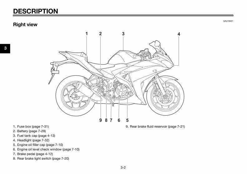
EAU10421
R
4
1.2.3.4.5.6.7.8.
page 7-21)
U2MS70E0.book Page 2 Thursday, December 18, 2014 1:46 PM
ESCRIPTION
3-2
ight view
9
1 2 3
8 7 6 5Fuse box (page 7-31)Battery (page 7-29)Fuel tank cap (page 4-13)Headlight (page 7-32)Engine oil filler cap (page 7-10)Engine oil level check window (page 7-10)Brake pedal (page 4-12)Rear brake light switch (page 7-20)
9. Rear brake fluid reservoir (

DESCRIPTION
3
EAU10431
C
7 8
1.2.3.4.5.6.7.8.
U2MS70E0.book Page 3 Thursday, December 18, 2014 1:46 PM
3-3
ontrols and instruments
1 2 3 4 5 6
Clutch lever (page 4-11)Left handlebar switches (page 4-10)Multi-function meter unit (page 4-4)Main switch/steering lock (page 4-1)Front brake fluid reservoir (page 7-21)Right handlebar switches (page 4-10)Throttle grip (page 7-16)Brake lever (page 4-12)

IN
4
M
Ththuspo
Alpocecoed
TI
Thwhonif t
lock the steering
Turn the handlebars all the way tothe left.Push the key in from the “ ” po-sition, and then turn it to “LOCK”while still pushing it.Remove the key.
ush.urn.
2
U2MS70E0.book Page 1 Thursday, December 18, 2014 1:46 PM
STRUMENT AND CONTROL FUNCTIONS
4-1
EAU10462
ain switch/steering lock
e main switch/steering lock controlse ignition and lighting systems, and ised to lock the steering. The varioussitions are described below.
EAU62480
(on)
l electrical circuits are supplied withwer; the meter lighting, taillight, li-nse plate light and auxiliary lightme on, and the engine can be start-. The key cannot be removed.
P
e headlight comes on automaticallyen the engine is started and stays until the key is turned to “ ”, evenhe engine stalls.
EAU54301
(off)
All electrical systems are off. The keycan be removed.
WARNING
EWA16371
Never turn the key to “ ” or “LOCK”
while the vehicle is moving. Other-
wise the electrical systems will be
switched off, which may result in
loss of control or an accident.
EAU60860
LOCK
The steering is locked, and all electricalsystems are off. The key can be re-moved.
To
1.
2.
3.
ONOFF
LOCK
1. P2. T
1

NTROL FUNCTIONS
4
T
Pw
EAU11081
h beam indicator light “ ”
is indicator light comes on when theh beam of the headlight is switched.
EAU62530
pressure warning light “ ”
is warning light comes on if the en-e oil pressure is low.e electrical circuit of the warningt can be checked by turning the key
“ ”. The warning light should come and remain on until the engine isrted.he warning light does not come onially when the key is turned to “ ”,ve a Yamaha dealer check the elec-al circuit.
TICEECA21210
he warning light comes on when
engine is running, stop the en-
e immediately and check oil level.
he oil level is below the minimum
el, add sufficient oil of the recom-
nded type to raise it up to the cor-
t level. If the oil pressure warning
ht remains on even if the oil level
1.2.
1
U2MS70E0.book Page 2 Thursday, December 18, 2014 1:46 PM
INSTRUMENT AND CO
4-2
o unlock the steering
ush the key in, and then turn it to “ ”hile still pushing it.
EAU49398
Indicator lights and warning lights
EAU11022
Turn signal indicator light “ ”
This indicator light flashes when a turnsignal light is flashing.
EAU11061
Neutral indicator light “ ”
This indicator light comes on when thetransmission is in the neutral position.
Hig
Thhigon
Oil
ThginThlightoonstaIf tinithatric
NO
If t
the
gin
If t
lev
me
rec
lig
Push.Turn.
2
1. Neutral indicator light “ ”2. High beam indicator light “ ”3. Turn signal indicator light “ ”4. Shift timing indicator light5. Oil pressure warning light “ ”6. Engine trouble warning light “ ”
6 5
31 2 4
km/hkm/LL/100km

IN
4
is
gi
ch
TI
If tstoilpaIf adde
En
Thif acircusefodeThligtoon
e indicator light does not come onally when the key is turned to “ ”,f the indicator light remains on, haveamaha dealer check the electricaluit.
U2MS70E0.book Page 3 Thursday, December 18, 2014 1:46 PM
STRUMENT AND CONTROL FUNCTIONS
4-3
correct, immediately turn the en-
ne off and have a Yamaha dealer
eck the vehicle.
P
he warning light does not go off afterarting the engine, check the engine level and add oil if necessary. (Seege 7-10.)the warning light remains on afterding engine oil, have a Yamahaaler check the vehicle.
EAU62790
gine trouble warning light “ ”
is warning light comes on or flashes problem is detected in the electricalcuit monitoring the engine. If this oc-rs, have a Yamaha dealer check thelf-diagnosis system. (See page 4-10r an explanation of the self-diagnosisvice.)e electrical circuit of the warninght can be checked by turning the key“ ”. The warning light should come for a few seconds, and then go off.
If the warning light does not come oninitially when the key is turned to “ ”,or if the warning light remains on, havea Yamaha dealer check the electricalcircuit.
TIP
The engine trouble warning light willcome on while the start switch ispushed, but this does not indicate amalfunction.
EAU62470
Shift timing indicator light
This indicator light can be set to comeon and go off at the desired enginespeeds and is used to inform the riderwhen it is time to shift to the next high-er gear. (See page 4-8 for a more de-tailed explanation of this indicator lightand on how to set it.)The electrical circuit of the indicatorlight can be checked by turning the keyto “ ”. The indicator light shouldcome on for a few seconds, and thengo off.
If thinitior ia Ycirc

NTROL FUNCTIONS
4
M
B
m
m
chometer
e tachometer allows the rider tonitor the engine speed and keep ithin the ideal power range.en the key is turned to “ ”, the ta-
ometer will sweep across the r/minge and then return to zero r/min iner to test the electrical circuit.
TICEECA10032
not operate the engine in the ta-
ometer red zone.
d zone: 12500 r/min and above
1.2.3.4.5.6.7.8.9.10
1
2
achometerachometer red zone
21
km/h
km/LL/100km
U2MS70E0.book Page 4 Thursday, December 18, 2014 1:46 PM
INSTRUMENT AND CO
4-4
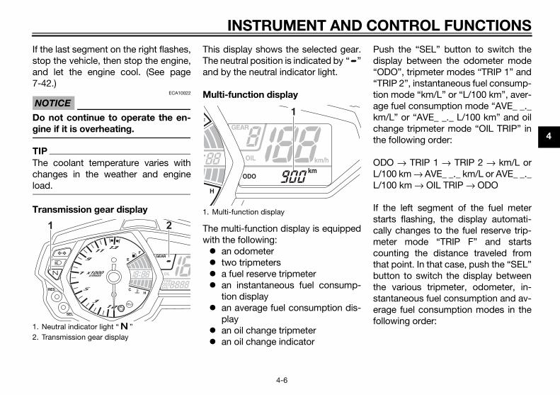
EAUN0841
ulti-function meter unit
WARNING
EWA12423
e sure to stop the vehicle before
aking any setting changes to the
ulti-function meter unit. Changing
settings while riding can distract the
operator and increase the risk of an
accident.
The multi-function meter unit isequipped with the following: a speedometer a tachometer a clock a fuel meter a coolant temperature meter a transmission gear display a multi-function display a shift timing indicator light a self-diagnosis device
TIP
Be sure to turn the key to “ ” beforeusing the “SEL” and “RES” buttons,except for setting the shift timing indi-cator light control mode.
Speedometer
The speedometer shows the vehicle’straveling speed.
Ta
ThmowitWhchranord
NO
Do
ch
Re
“SEL” button“RES” buttonTachometerFuel meterShift timing indicator lightClockTransmission gear displaySpeedometerMulti-function display.Coolant temperature meter
10 9
3 4 65 7 8
km/h
km/LL/100km
1. T2. T

IN
4
Cl
Thtu
To12
3
4
5
6
ing cycle is repeated until thelfunction is corrected: fuel level seg-nts flash eight times, then go off forroximately three seconds. If thisurs, have a Yamaha dealer check electrical circuit.
olant temperature meter
coolant temperature meter indi-es the temperature of the coolant.en the key is turned to “ ”, the dis-y segments of the digital coolantperature gauge will sweep once
oss the temperature range and thenrn to “C” in order to test the electri-circuit.
1.
oolant temperature meter1
U2MS70E0.book Page 5 Thursday, December 18, 2014 1:46 PM
STRUMENT AND CONTROL FUNCTIONS
4-5
ock
e clock displays when the key isrned to “ ”.
set the clock. Turn the key to “ ”.. Push the “SEL” button and “RES”
button together for at least twoseconds.
. When the hour digits start flash-ing, push the “RES” button to setthe hours.
. Push the “SEL” button, and theminute digits will start flashing.
. Push the “RES” button to set theminutes.
. Push the “SEL” button and thenrelease it to start the clock.
Fuel meter
The fuel meter indicates the amount offuel in the fuel tank.When the key is turned to “ ”, the dis-play segments of the fuel meter willsweep once across the fuel level rangeand then return to the current amountin order to test the electrical circuit.The display segments of the fuel meterdisappear towards “E” (Empty) as thefuel level decreases. When the lastsegment starts flashing, refuel as soonas possible.
TIP
This fuel meter is equipped with a self-diagnosis system. If a problem is de-tected in the electrical circuit, the fol-
lowmameappoccthe
Co
ThecatWhplatemacrretucal
Clock
1
1. Fuel meter
1
1. C
NTROL FUNCTIONS
4
Ifsta7
N
D
g
T
Tclo
T
sh the “SEL” button to switch theplay between the odometer modeDO”, tripmeter modes “TRIP 1” andIP 2”, instantaneous fuel consump-
n mode “km/L” or “L/100 km”, aver-e fuel consumption mode “AVE_ _._/L” or “AVE_ _._ L/100 km” and oil
ange tripmeter mode “OIL TRIP” in following order:
O → TRIP 1 → TRIP 2 → km/L or00 km → AVE_ _._ km/L or AVE_ _._00 km → OIL TRIP → ODO
the left segment of the fuel meterrts flashing, the display automati-lly changes to the fuel reserve trip-ter mode “TRIP F” and startsunting the distance traveled fromt point. In that case, push the “SEL”tton to switch the display between various tripmeter, odometer, in-ntaneous fuel consumption and av-ge fuel consumption modes in the
lowing order:1.2.
U2MS70E0.book Page 6 Thursday, December 18, 2014 1:46 PM
INSTRUMENT AND CO
4-6
the last segment on the right flashes,op the vehicle, then stop the engine,nd let the engine cool. (See page-42.)
OTICEECA10022
o not continue to operate the en-
ine if it is overheating.
IP
he coolant temperature varies withhanges in the weather and enginead.
ransmission gear display
This display shows the selected gear.The neutral position is indicated by “ ”and by the neutral indicator light.
Multi-function display
The multi-function display is equippedwith the following: an odometer two tripmeters a fuel reserve tripmeter an instantaneous fuel consump-
tion display an average fuel consumption dis-
play an oil change tripmeter an oil change indicator
Pudis“O“TRtioagkmchthe
ODL/1L/1
If stacamecothabuthestaerafol
Neutral indicator light “ ”Transmission gear display
1 21. Multi-function display
1

IN
4
TR_._TRTR
ToingthonIf mmpr5
In
di
rage fuel consumption display
average fuel consumption display be set to either “AVE_ _._ km/L” orE_ _._ L/100 km”.
s display shows the average fuelsumption since it was last reset.“AVE_ _._ km/L”: The average dis-tance that can be traveled on 1.0 Lof fuel is shown.“AVE_ _._ L/100 km”: The averageamount of fuel necessary to travel100 km is shown.
switch between the average fuelsumption displays, push the “SEL”ton for one second.reset the average fuel consumptionlay, push the “RES” button for att one second.
1.
verage fuel consumption display
1
U2MS70E0.book Page 7 Thursday, December 18, 2014 1:46 PM
STRUMENT AND CONTROL FUNCTIONS
4-7
IP F → km/L or L/100 km → AVE_ km/L or AVE_ _._ L/100 km → OILIP → ODO → TRIP 1 → TRIP 2 →IP F
reset a tripmeter, select it by push- the “SEL” button, and then push
e “RES” button for at least one sec-d.
you do not reset the fuel reserve trip-eter manually, it resets itself auto-atically and the display returns to theior mode after refueling and travelingkm (3 mi).
stantaneous fuel consumption
splay
The instantaneous fuel consumptiondisplay can be set to either “km/L” or“L/100 km”. “km/L”: The distance that can be
traveled on 1.0 L of fuel under thecurrent riding conditions is shown.
“L/100 km”: The amount of fuelnecessary to travel 100 km underthe current riding conditions isshown.
To switch between the instantaneousfuel consumption displays, push the“SEL” button for one second.
TIP
If traveling at speeds under 20 km/h(12 mi/h), “_ _._” is displayed.
Ave
Thecan“AVThicon
To conbutTo displeas
Instantaneous fuel consumption display
1
1. A

NTROL FUNCTIONS
4
T
Asuth
O
Td(i.Ta5cc
ift timing indicator light
e shift timing indicator light has fourtings which can be adjusted.
Flashing pattern: this function al-lows you to choose whether or notthe indicator light will come on andwhether it should flash or stay onwhen activated.Activation point: this function al-lows you to select the enginespeed at which the indicator lightis activated.Deactivation point: this functionallows you to select the enginespeed at which the indicator lightis deactivated.
1.2.
hift timing indicator lightrightness level display
1
2
km/h
U2MS70E0.book Page 8 Thursday, December 18, 2014 1:46 PM
INSTRUMENT AND CO
4-8
IP
fter resetting the average fuel con-mption display, “_ _._” is shown untile vehicle has traveled 1 km (0.6 mi).
il change tripmeter
he oil change tripmeter shows theistance traveled since it was last resete., since the last oil change).he oil change indicator “OIL” will flasht the initial 1000 km (600 mi) and every000 km (3000 mi) thereafter to indi-ate that the engine oil should behanged.
After changing the engine oil, reset theoil change tripmeter and the oil changeindicator. To reset them both, selectthe oil change tripmeter, and then pushthe “RES” button for one second.Then, while “OIL” and the oil changetripmeter are flashing, push the “RES”button for three seconds. The oilchange indicator will be reset.If the engine oil is changed before theoil change indicator comes on (i.e., be-fore the periodic oil change interval hasbeen reached), the oil change tripmetermust be reset for the next periodic oilchange to be indicated at the correcttime.
Sh
Thset
Oil change indicator “OIL”Oil change tripmeter
21
1. S2. B

IN
4
To123
To1
Push the “SEL” button to confirmthe selected engine speed. Thecontrol mode changes to the de-activation point setting mode.
set the deactivation point
The shift timing indicator light de-activation point can be set be-tween 7000 r/min and 13500r/min. From 7000 r/min to 12000r/min, the indicator light can be setin increments of 500 r/min. From12000 r/min to 13500 r/min, the in-dicator light can be set in incre-ments of 200 r/min.Be sure to set the deactivationpoint to a higher engine speedthan for the activation point, other-wise the shift timing indicator lightwill not come on.
Push the “RES” button to selectthe desired engine speed for de-activating the indicator light.Push the “SEL” button to confirmthe selected engine speed. Thecontrol mode changes to thebrightness setting mode.
U2MS70E0.book Page 9 Thursday, December 18, 2014 1:46 PM
STRUMENT AND CONTROL FUNCTIONS
4-9
Brightness: this function allowsyou to adjust the brightness of theindicator light.
adjust the shift timing indicator light. Turn the key to “ ”.. Push and hold the “SEL” button.. Turn the key to “ ”, and then re-
lease the “SEL” button after fiveseconds. The shift timing indicatorlight can now be adjusted.
set the flashing pattern. Push the “RES” button to select
one of the following flashing pat-tern settings: On: the indicator light stays
on when activated. (This set-ting is selected when the indi-cator light stays on.)
Flash: the indicator lightflashes when activated. (Thissetting is selected when theindicator light flashes fourtimes per second.)
Off: the indicator light is deac-tivated; in other words, itdoes not come on or flash.
(This setting is selected whenthe indicator light flashesonce every two seconds.)
2. Push the “SEL” button to confirmthe selected flashing pattern. Theshift timing indicator light changesto the activation point settingmode.
The tachometer will show the currentsetting r/min for the activation pointand deactivation point setting modes.
To set the shift activation point
TIP
The shift timing indicator light activa-tion point can be set between 7000r/min and 13500 r/min. From 7000r/min to 12000 r/min, the indicator lightcan be set in increments of 500 r/min.From 12000 r/min to 13500 r/min, theindicator light can be set in incrementsof 200 r/min.
1. Push the “RES” button to selectthe desired engine speed for acti-vating the indicator light.
2.
To
TIP
1.
2.
NTROL FUNCTIONS
4
T
S
Tac
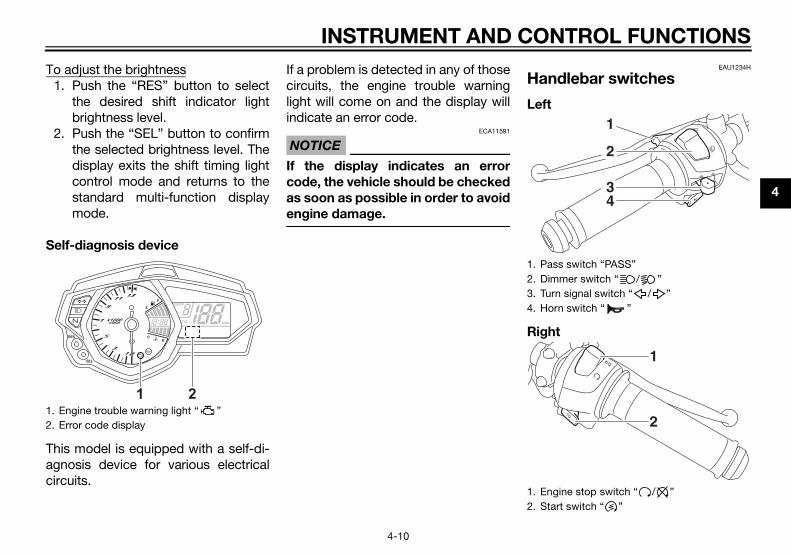
EAU1234H
ndlebar switches
ft
ht
1.2.
ass switch “PASS”immer switch “ / ”urn signal switch “ / ”orn switch “ ”
ngine stop switch “ / ”tart switch “ ”
43
1
2
2
1
U2MS70E0.book Page 10 Thursday, December 18, 2014 1:46 PM
INSTRUMENT AND CO
4-10
o adjust the brightness1. Push the “RES” button to select
the desired shift indicator lightbrightness level.
2. Push the “SEL” button to confirmthe selected brightness level. Thedisplay exits the shift timing lightcontrol mode and returns to thestandard multi-function displaymode.
elf-diagnosis device
his model is equipped with a self-di-gnosis device for various electricalircuits.
If a problem is detected in any of thosecircuits, the engine trouble warninglight will come on and the display willindicate an error code.
NOTICEECA11591
If the display indicates an error
code, the vehicle should be checked
as soon as possible in order to avoid
engine damage.
Ha
Le
Rig
Engine trouble warning light “ ”Error code display
21
km/h
1. P2. D3. T4. H
1. E2. S

IN
4
Pa
Pr
Di
Sebe
TI
WonWbo
Tu
Toswtureteligtu
Ho
Pr
EAU12821
tch lever
clutch lever is located at the leftdlebar grip. To disengage thech, pull the lever toward the han-bar grip. To engage the clutch, re-e the lever. The lever should be
led rapidly and released slowly forooth clutch operation. clutch lever is equipped with ach switch, which is part of the igni- circuit cut-off system. (See page0.)
lutch lever
1
U2MS70E0.book Page 11 Thursday, December 18, 2014 1:46 PM
STRUMENT AND CONTROL FUNCTIONS
4-11
EAU12361
ss switch “PASS”
ess this switch to flash the headlight.
EAU62540
mmer switch “ / ”
t this switch to “ ” for the higham and to “ ” for the low beam.
P
hen the switch is set to low beam,ly the right headlight bulb comes on.hen the switch is set to high beam,th headlight bulbs come on.
EAU12461
rn signal switch “ / ”
signal a right-hand turn, push thisitch to “ ”. To signal a left-hand
rn, push this switch to “ ”. Whenleased, the switch returns to the cen-r position. To cancel the turn signalhts, push the switch in after it has re-rned to the center position.
EAU12501
rn switch “ ”
ess this switch to sound the horn.
EAU12661
Engine stop switch “ / ”
Set this switch to “ ” before startingthe engine. Set this switch to “ ” tostop the engine in case of an emergen-cy, such as when the vehicle overturnsor when the throttle cable is stuck.
EAU12713
Start switch “ ”
Push this switch to crank the enginewith the starter. See page 6-1 for start-ing instructions prior to starting the en-gine.
EAU62500
The engine trouble warning light willcome on when the key is turned to “ ”and the start switch is pushed, but thisdoes not indicate a malfunction.
Clu
ThehanclutdleleaspulsmThecluttion4-2
1. C

NTROL FUNCTIONS
4
S
Tsicshstth
EAU12944
ake pedal
e brake pedal is located on the righte of the motorcycle. To apply ther brake, press down on the brakedal.
1. rake pedal
1
U2MS70E0.book Page 12 Thursday, December 18, 2014 1:46 PM
INSTRUMENT AND CO
4-12
EAU12872
hift pedal
he shift pedal is located on the leftde of the motorcycle and is used inombination with the clutch lever whenifting the gears of the 6-speed con-ant-mesh transmission equipped onis motorcycle.
EAU12892
Brake lever
The brake lever is located on the rightside of the handlebar. To apply thefront brake, pull the lever toward thethrottle grip.
Br
Thsidreape
Shift pedal
11. Brake lever
1
1. B

IN
4
Fu
To
Opseit reop
To
1
2
EAU13222
elke sure there is sufficient gasoline in tank.
WARNING
EWA10882
soline and gasoline vapors are
remely flammable. To avoid fires
explosions and to reduce the
of injury when refueling, follow
se instructions.
Before refueling, turn off the en-gine and be sure that no one is sit-ting on the vehicle. Never refuelwhile smoking, or while in the vi-cinity of sparks, open flames, orother sources of ignition such asthe pilot lights of water heatersand clothes dryers.Do not overfill the fuel tank. Whenrefueling, be sure to insert thepump nozzle into the fuel tank fillerhole. Stop filling when the fuelreaches the bottom of the fillertube. Because fuel expands whenit heats up, heat from the engine orthe sun can cause fuel to spill outof the fuel tank.
1.2.
U2MS70E0.book Page 13 Thursday, December 18, 2014 1:46 PM
STRUMENT AND CONTROL FUNCTIONS
4-13
EAU13075
el tank cap
open the fuel tank cap
en the fuel tank cap lock cover, in-rt the key into the lock, and then turn1/4 turn clockwise. The lock will beleased and the fuel tank cap can beened.
close the fuel tank cap
. Push the fuel tank cap into posi-tion with the key inserted in thelock.
. Turn the key counterclockwise tothe original position, remove it,and then close the lock cover.
TIP
The fuel tank cap cannot be closed un-less the key is in the lock. In addition,the key cannot be removed if the cap isnot properly closed and locked.
WARNING
EWA11092
Make sure that the fuel tank cap is
properly closed after filling fuel.
Leaking fuel is a fire hazard.
FuMathe
Ga
ext
and
risk
the
1.
2.
Fuel tank cap lock coverUnlock.
2 1

NTROL FUNCTIONS
4
G
c
li
b
s
o
y
unleaded fuel. Use of unleaded fuell extend spark plug life and reduceintenance costs.sohol
ere are two types of gasohol: gaso-l containing ethanol and that con-ning methanol. Gasohol containinganol can be used if the ethanol con-t does not exceed 10% (E10). Gas-ol containing methanol is notommended by Yamaha because it
n cause damage to the fuel systemvehicle performance problems.
1.2.
U2MS70E0.book Page 14 Thursday, December 18, 2014 1:46 PM
INSTRUMENT AND CO
4-14
3. Wipe up any spilled fuel immedi-ately. NOTICE: Immediately
wipe off spilled fuel with a clean,
dry, soft cloth, since fuel may
deteriorate painted surfaces or
plastic parts. [ECA10072]
4. Be sure to securely close the fueltank cap.
WARNING
EWA15152
asoline is poisonous and can
ause injury or death. Handle gaso-
ne with care. Never siphon gasoline
y mouth. If you should swallow
ome gasoline or inhale a lot of gas-
line vapor, or get some gasoline in
our eyes, see your doctor immedi-
ately. If gasoline spills on your skin,
wash with soap and water. If gaso-
line spills on your clothing, change
your clothes.
EAU13315
NOTICEECA11401
Use only unleaded gasoline. The use
of leaded gasoline will cause severe
damage to internal engine parts,
such as the valves and piston rings,
as well as to the exhaust system.
Your Yamaha engine has been de-signed to use regular unleaded gaso-line with a pump octane number[(R+M)/2] of 86 or higher, or a researchoctane number of 91 or higher. Ifknocking (or pinging) occurs, use agasoline of a different brand or premi-
umwilmaGa
Thhotaiethtenohreccaor
Fuel tank filler tubeMaximum fuel level
21
Recommended fuel:Regular unleaded gasoline (Gasohol (E10) acceptable)
Fuel tank capacity:14 L (3.7 US gal, 3.08 Imp.gal)
Fuel reserve amount:3.0 L (0.79 US gal, 0.66 Imp.gal)

IN
4
Fuov
Be
TICEECA10702
only unleaded gasoline. The use
leaded gasoline will cause unre-
rable damage to the catalytic
verter.
1.2.
U2MS70E0.book Page 15 Thursday, December 18, 2014 1:46 PM
STRUMENT AND CONTROL FUNCTIONS
4-15
EAUN0790
el tank breather hose and erflow hose
fore operating the motorcycle:Check each hose connection.Check each hose for cracks ordamage, and replace if necessary.Make sure that the end of eachhose is not blocked, and clean ifnecessary.Make sure that the end of fuel tankbreather hose is positioned out-side of the cowling.
EAU13434
Catalytic converterThis model is equipped with a catalyticconverter in the exhaust system.
WARNING
EWA10863
The exhaust system is hot after op-
eration. To prevent a fire hazard or
burns:
Do not park the vehicle near
possible fire hazards such as
grass or other materials that
easily burn.
Park the vehicle in a place
where pedestrians or children
are not likely to touch the hot
exhaust system.
Make sure that the exhaust sys-
tem has cooled down before
doing any maintenance work.
Do not allow the engine to idle
more than a few minutes. Long
idling can cause a build-up of
heat.
NO
Use
of
pai
con
Fuel tank overflow hoseFuel tank breather hose
2
1
NTROL FUNCTIONS
4
S
P
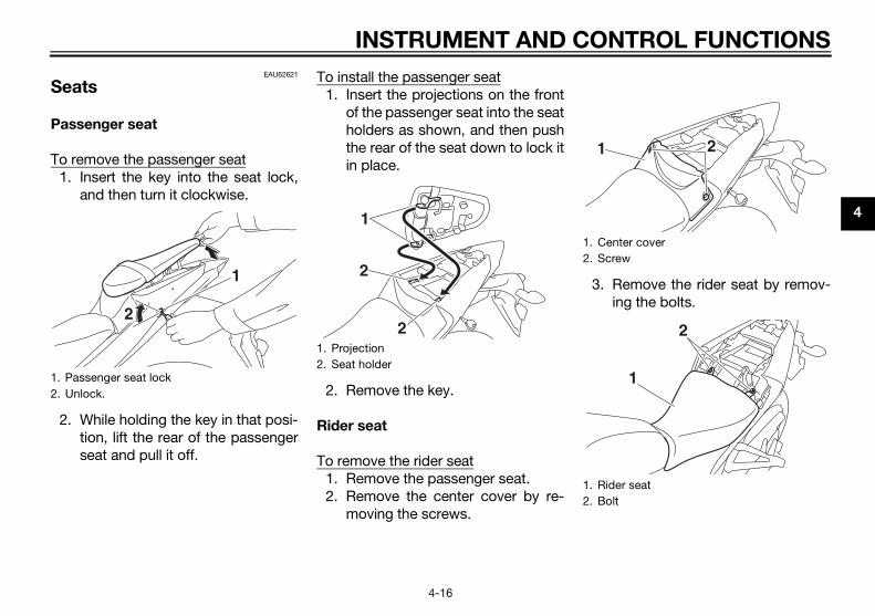
T
. Remove the rider seat by remov-ing the bolts.
1.2.
enter covercrew
ider seatolt
2
1
2
U2MS70E0.book Page 16 Thursday, December 18, 2014 1:46 PM
INSTRUMENT AND CO
4-16
EAU62621
eats
assenger seat
o remove the passenger seat1. Insert the key into the seat lock,
and then turn it clockwise.
2. While holding the key in that posi-tion, lift the rear of the passengerseat and pull it off.
To install the passenger seat1. Insert the projections on the front
of the passenger seat into the seatholders as shown, and then pushthe rear of the seat down to lock itin place.
2. Remove the key.
Rider seat
To remove the rider seat1. Remove the passenger seat.2. Remove the center cover by re-
moving the screws.
3
Passenger seat lockUnlock.
2
1
1. Projection2. Seat holder
1
2
2
1. C2. S
1. R2. B
1

IN
4
To1
23
4
TI
Mse
release a helmet from a helmet
der
ove the passenger seat, remove helmet from the helmet holder, andn install the seat.
1.2.
elmetassenger seat
1
2
U2MS70E0.book Page 17 Thursday, December 18, 2014 1:46 PM
STRUMENT AND CONTROL FUNCTIONS
4-17
install the rider seat. Insert the projection on the front of
the rider seat into the seat holderas shown, and then place the seatin the original position.
. Install the rider seat bolts.
. Install the center cover by install-ing the screws.
. Install the passenger seat.
P
ake sure that the seats are properlycured before riding.
EAU62930
Helmet holders
The helmet holders are located on thebottom of the passenger seat.
To secure a helmet to a helmet hold-
er
1. Remove the passenger seat. (Seepage 4-16.)
2. Attach a helmet to a helmet hold-er, and then securely install thepassenger seat. WARNING! Nev-
er ride with a helmet attached to
the helmet holder, since the hel-
met may hit objects, causing
loss of control and possibly an
accident. [EWA10162]
To
hol
Remthethe
ProjectionSeat holder
1
2
1. Helmet holder
1 1. H2. P

NTROL FUNCTIONS
4
S
Tu4Witsuthinw
D
1
EAU62561
justing the shock absorber semblyis shock absorber assembly isuipped with a spring preload adjust- ring.
TICEECA10102
avoid damaging the mechanism,
not attempt to turn beyond the
ximum or minimum settings.
just the spring preload as follows. increase the spring preload andreby harden the suspension, turn adjusting ring in direction (a). Tocrease the spring preload and there- soften the suspension, turn the ad-ting ring in direction (b).
Align the appropriate notch in theadjusting ring with the position in-dicator on the shock absorber.Use the special wrench and theextension bar included in the own-er’s tool kit to make the adjust-ment.
1.
U2MS70E0.book Page 18 Thursday, December 18, 2014 1:46 PM
INSTRUMENT AND CO
4-18
EAU62550
torage compartment
he storage compartment is locatednder the passenger seat. (See page-16.)hen storing documents or other
ems in the storage compartment, bere to wrap them in a plastic bag soat they will not get wet. When wash-g the vehicle, be careful not to let anyater enter the storage compartment.
WARNING
EWA15401
o not exceed the maximum load of
60 kg (353 lb) for the vehicle.
EAU39672
Rear view mirrorsThe rear view mirrors of this vehiclecan be folded forward or backward forparking in narrow spaces. Fold the mir-rors back to their original position be-fore riding.
WARNING
EWA14372
Be sure to fold the rear view mirrors
back to their original position before
riding.
AdasTheqing
NO
To
do
ma
AdTothethedebyjus
Storage compartment
1
1. Riding position2. Parking position
1 1
2 2
2 2

IN
4
EAU15306
estand sidestand is located on the left of the frame. Raise the sidestand
ower it with your foot while holding vehicle upright.
built-in sidestand switch is part of ignition circuit cut-off system,ch cuts the ignition in certain situa-s. (See the following section for anlanation of the ignition circuit cut-system.)
WARNING
EWA10242
vehicle must not be ridden with
sidestand down, or if the side-
nd cannot be properly moved up
does not stay up), otherwise the
estand could contact the ground
distract the operator, resulting
a possible loss of control.
aha’s ignition circuit cut-off
tem has been designed to assist
operator in fulfilling the respon-
ility of raising the sidestand be-
e starting off. Therefore, check
1.2.3.4.
U2MS70E0.book Page 19 Thursday, December 18, 2014 1:46 PM
STRUMENT AND CONTROL FUNCTIONS
4-19
EAU15152
Luggage strap holders
There is a luggage strap holder oneach passenger footrest.
SidThesideor lthe
TIP
Thethewhitionexpoff
The
the
sta
(or
sid
and
in
Yam
sys
the
sib
for
Extension barSpecial wrenchSpring preload adjusting ringPosition indicator
Spring preload setting:Minimum (soft):
1Standard:
3Maximum (hard):
7
7 6 5 4 3 2 1
2 13
4
(b) (a)
1. Luggage strap holder
1

NTROL FUNCTIONS
4
th
Y
fu
U2MS70E0.book Page 20 Thursday, December 18, 2014 1:46 PM
INSTRUMENT AND CO
4-20
is system regularly and have a
amaha dealer repair it if it does not
nction properly.
EAU44893
Ignition circuit cut-off systemThe ignition circuit cut-off system(comprising the sidestand switch,clutch switch and neutral switch) hasthe following functions. It prevents starting when the
transmission is in gear and thesidestand is up, but the clutch le-ver is not pulled.
It prevents starting when thetransmission is in gear and theclutch lever is pulled, but the side-stand is still down.
It cuts the running engine whenthe transmission is in gear and thesidestand is moved down.
Periodically check the operation of theignition circuit cut-off system accord-ing to the following procedure.

IN
4 h may not be working correctly. should not be ridden until
aha dealer.
itch may not be working correctly. should not be ridden until
aha dealer.
may not be working correctly. should not be ridden until
aha dealer.
is noted, have a Yamaha system before riding.
U2MS70E0.book Page 21 Thursday, December 18, 2014 1:46 PM
STRUMENT AND CONTROL FUNCTIONS
4-21
With the engine turned off:1. Move the sidestand down.2. Make sure that the engine stop switch is set to “3. Turn the key on. 4. Shift the transmission into the neutral position.5. Push the start switch.Does the engine start?
With the engine still running:6. Move the sidestand up.7. Keep the clutch lever pulled.8. Shift the transmission into gear.9. Move the sidestand down.Does the engine stall?
After the engine has stalled:10. Move the sidestand up.11. Keep the clutch lever pulled.12. Push the start switch.Does the engine start?
The system is OK. The motorcycle can be ridden.
The neutral switcThe motorcyclechecked by a Yam
The sidestand swThe motorcyclechecked by a Yam
The clutch switchThe motorcyclechecked by a Yam
YES NO
YES NO
YES NO
If a malfunctiondealer check the
WARNING
”.

PERATION CHECKS
5
EAU15599
In ndition. Always follow the inspectiona
EWA11152
F accident or equipment damage.
D ted by the procedures provided in
th
B
PAGE
Facks or
4-13, 4-15
E 7-10
C 7-13
F 7-21, 7-21
U2MS70E0.book Page 1 Thursday, December 18, 2014 1:46 PM
FOR YOUR SAFETY – PRE-O
5-1
spect your vehicle each time you use it to make sure the vehicle is in safe operating cond maintenance procedures and schedules described in the Owner’s Manual.
WARNING
ailure to inspect or maintain the vehicle properly increases the possibility of an
o not operate the vehicle if you find any problem. If a problem cannot be correc
is manual, have the vehicle inspected by a Yamaha dealer.
efore using this vehicle, check the following points:
ITEM CHECKS
uel
• Check fuel level in fuel tank.• Refuel if necessary.• Check fuel line for leakage.• Check fuel tank breather hose and overflow hose for obstructions, cr
damage, and check hose connections.
ngine oil• Check oil level in engine.• If necessary, add recommended oil to specified level.• Check vehicle for oil leakage.
oolant• Check coolant level in reservoir.• If necessary, add recommended coolant to specified level.• Check cooling system for leakage.
ront brake
• Check operation.• If soft or spongy, have Yamaha dealer bleed hydraulic system.• Check brake pads for wear.• Replace if necessary.• Check fluid level in reservoir.• If necessary, add specified brake fluid to specified level.• Check hydraulic system for leakage.

F
5
R 7-21, 7-21
C 7-18
T ricate ca- 7-16, 7-26
C 7-25
D 7-23, 7-25
W 7-16, 7-18
B 7-26
B 7-27
S 7-27
PAGE
U2MS70E0.book Page 2 Thursday, December 18, 2014 1:46 PM
OR YOUR SAFETY – PRE-OPERATION CHECKS
5-2
ear brake
• Check operation.• If soft or spongy, have Yamaha dealer bleed hydraulic system.• Check brake pads for wear.• Replace if necessary.• Check fluid level in reservoir.• If necessary, add specified brake fluid to specified level.• Check hydraulic system for leakage.
lutch
• Check operation.• Lubricate cable if necessary.• Check lever free play.• Adjust if necessary.
hrottle grip
• Make sure that operation is smooth.• Check throttle grip free play.• If necessary, have Yamaha dealer adjust throttle grip free play and lub
ble and grip housing.
ontrol cables• Make sure that operation is smooth.• Lubricate if necessary.
rive chain
• Check chain slack.• Adjust if necessary.• Check chain condition.• Lubricate if necessary.
heels and tires
• Check for damage.• Check tire condition and tread depth.• Check air pressure.• Correct if necessary.
rake and shift pedals• Make sure that operation is smooth.• Lubricate pedal pivoting points if necessary.
rake and clutch levers• Make sure that operation is smooth.• Lubricate lever pivoting points if necessary.
idestand• Make sure that operation is smooth.• Lubricate pivot if necessary.
ITEM CHECKS

PERATION CHECKS
5
C —
Ia
—
S . 4-19
PAGE
U2MS70E0.book Page 3 Thursday, December 18, 2014 1:46 PM
FOR YOUR SAFETY – PRE-O
5-3
hassis fasteners• Make sure that all nuts, bolts and screws are properly tightened.• Tighten if necessary.
nstruments, lights, signals nd switches
• Check operation.• Correct if necessary.
idestand switch • Check operation of ignition circuit cut-off system.• If system is not working correctly, have Yamaha dealer check vehicle
ITEM CHECKS

O
6
Rebethun
Fa
th
tro
or
EAUN0680
rting the enginerder for the ignition circuit cut-off
tem to enable starting, one of thewing conditions must be met:The transmission is in the neutralposition.The transmission is in gear withthe clutch lever pulled and thesidestand up.See page 4-20 for more informa-tion.Turn the key to “ ” and makesure that the engine stop switch isset to “ ”.The engine trouble warning lightshould come on for a few sec-onds, then go off. NOTICE: If the
warning light does not go off,
have a Yamaha dealer check its
electrical circuit. [ECAT1121]
Shift the transmission into theneutral position. The neutral indi-cator light should come on. If not,ask a Yamaha dealer to check theelectrical circuit.Start the engine by pushing thestart switch.
U2MS70E0.book Page 1 Thursday, December 18, 2014 1:46 PM
PERATION AND IMPORTANT RIDING POINTS
6-1
EAU15952
ad the Owner’s Manual carefully tocome familiar with all controls. Ifere is a control or function you do notderstand, ask your Yamaha dealer.
WARNING
EWA10272
ilure to familiarize yourself with
e controls can lead to loss of con-
l, which could cause an accident
injury.
EAU62513
TIP
This model is equipped with: a lean angle sensor to stop the en-
gine in case of a turnover. In thiscase, the display will indicate errorcode 30, but this is not a malfunc-tion. Turn the key to “ ” and thento “ ” to clear the error code.Failing to do so will prevent the en-gine from starting even though theengine will crank when pushingthe start switch.
an engine auto-stop system. Theengine stops automatically if leftidling for 20 minutes. If the enginestops, simply push the startswitch to restart the engine.
StaIn osysfollo
1.
2.
3.

ANT RIDING POINTS
6
N
F
c
c
TICEECA10261
Even with the transmission in
the neutral position, do not
coast for long periods of time
with the engine off, and do not
tow the motorcycle for long dis-
tances. The transmission is
properly lubricated only when
the engine is running. Inade-
quate lubrication may damage
the transmission.
Always use the clutch while
changing gears to avoid dam-
aging the engine, transmission,
and drive train, which are not
designed to withstand the
shock of forced shifting.
EAU16682
start out and accelerate
. Pull the clutch lever to disengagethe clutch.
. Shift the transmission into firstgear. The neutral indicator lightshould go out.
. Open the throttle gradually, and atthe same time, release the clutchlever slowly.
U2MS70E0.book Page 2 Thursday, December 18, 2014 1:46 PM
OPERATION AND IMPORT
6-2
If the engine fails to start, releasethe start switch, wait a few sec-onds, and then try again. Eachstarting attempt should be asshort as possible to preserve thebattery. Do not crank the enginemore than 10 seconds on any oneattempt.
OTICEECA11043
or maximum engine life, never ac-
elerate hard when the engine is
old!
EAU16673
Shifting
Shifting gears lets you control theamount of engine power available forstarting off, accelerating, climbing hills,etc.The gear positions are shown in the il-lustration.
TIP
To shift the transmission into the neu-tral position, press the shift pedal downrepeatedly until it reaches the end of itstravel, and then slightly raise it.
NO
To
1
2
3
1. Shift pedal2. Neutral position
1N23456
1
2

O
6
4
5
6
7
TI
Wingsh
To
1
2
3
EAU58280
ommended shift points
recommended shift points duringeleration and deceleration arewn in the table below.
hift up points:1st → 2nd: 20 km/h (12 mi/h)2nd → 3rd: 30 km/h (19 mi/h)3rd → 4th: 40 km/h (25 mi/h)4th → 5th: 50 km/h (31 mi/h)5th → 6th: 60 km/h (37 mi/h)
hift down points:6th → 5th: 45 km/h (28 mi/h)5th → 4th: 35 km/h (22 mi/h)4th → 3rd: 25 km/h (16 mi/h)
U2MS70E0.book Page 3 Thursday, December 18, 2014 1:46 PM
PERATION AND IMPORTANT RIDING POINTS
6-3
. At the recommended shift pointsshown in the following table, closethe throttle, and at the same time,quickly pull the clutch lever in.
. Shift the transmission into secondgear. (Make sure not to shift thetransmission into the neutral posi-tion.)
. Open the throttle part way andgradually release the clutch lever.
. Follow the same procedure whenshifting to the next higher gear.
P
hen shifting gears in normal operat- conditions, use the recommended
ift points.
EAU58270
decelerate
. Release the throttle and applyboth the front and the rear brakessmoothly to slow the motorcycle.
. At the recommended shift pointsshown in the following table, shiftto a lower gear.
. When the motorcycle reaches 25km/h (16 mi/h), the engine is aboutto stall or runs roughly, pull the
clutch lever in, use the brakes toslow the motorcycle, and continueto downshift as necessary.
4. Once the motorcycle hasstopped, the transmission can beshifted into the neutral position.The neutral indicator light shouldcome on and then the clutch levercan be released.
WARNING
EWA17380
Improper braking can cause
loss of control or traction. Al-
ways use both brakes and apply
them smoothly.
Make sure that the motorcycle
and the engine have sufficiently
slowed before shifting to a low-
er gear. Engaging a lower gear
when the vehicle or engine
speed is too high could make
the rear wheel lose traction or
the engine to over-rev. This
could cause loss of control, an
accident and injury. It could also
cause engine or drive train dam-
age.
Rec
Theaccsho
S
S

ANT RIDING POINTS
6
ETinbthloSp1thtoDtlmm
0
Ar/m
b
tr
1
Ar/
EAU17214
rkingen parking, stop the engine, andn remove the key from the mainitch.
WARNING
EWA10312
Since the engine and exhaust
system can become very hot,
park in a place where pedestri-
ans or children are not likely to
touch them and be burned.
Do not park on a slope or on soft
ground, otherwise the vehicle
may overturn, increasing the
risk of a fuel leak and fire.
Do not park near grass or other
flammable materials which
might catch fire.
U2MS70E0.book Page 4 Thursday, December 18, 2014 1:46 PM
OPERATION AND IMPORT
6-4
EAU16842
ngine break-inhere is never a more important period the life of your engine than the periodetween 0 and 1600 km (1000 mi). Foris reason, you should read the fol-wing material carefully.ince the engine is brand new, do notut an excessive load on it for the first600 km (1000 mi). The various parts ine engine wear and polish themselves the correct operating clearances.uring this period, prolonged full-throt-e operation or any condition thatight result in engine overheatingust be avoided.
EAU17094
–1000 km (0–600 mi)
void prolonged operation above 7000min. NOTICE: After 1000 km (600
i) of operation, the engine oil must
e changed and the oil filter car-
idge or element replaced. [ECA10303]
000–1600 km (600–1000 mi)
void prolonged operation above 8400min.
1600 km (1000 mi) and beyond
The vehicle can now be operated nor-mally.
NOTICEECA10311
Keep the engine speed out of
the tachometer red zone.
If any engine trouble should oc-
cur during the engine break-in
period, immediately have a
Yamaha dealer check the vehi-
cle.
PaWhthesw

P
7
PelubsapovepoadplThmconopegrthbe
Fa
cl
tiv
yo
se
yo
vic
se
EAU17303
ission controls not only function toure cleaner air, but are also vital toper engine operation and maximumformance. In the following periodicintenance charts, the services relat-to emissions control are groupedarately. These services requirecialized data, knowledge, andipment. Maintenance, replace-
nt, or repair of the emission controlices and systems may be per-ed by any repair establishment or
ividual that is certified (if applicable).aha dealers are trained and
ipped to perform these particularvices.
U2MS70E0.book Page 1 Thursday, December 18, 2014 1:46 PM
ERIODIC MAINTENANCE AND ADJUSTMENT
7-1
EAU17245
riodic inspection, adjustment, andrication will keep your vehicle in the
fest and most efficient conditionssible. Safety is an obligation of thehicle owner/operator. The most im-rtant points of vehicle inspection,justment, and lubrication are ex-
ained on the following pages.e intervals given in the periodicaintenance charts should be simplynsidered as a general guide underrmal riding conditions. However, de-nding on the weather, terrain, geo-aphical location, and individual use,e maintenance intervals may need to shortened.
WARNING
EWA10322
ilure to properly maintain the vehi-
e or performing maintenance ac-
ities incorrectly may increase
ur risk of injury or death during
rvice or while using the vehicle. If
u are not familiar with vehicle ser-
e, have a Yamaha dealer perform
rvice.
WARNING
EWA15123
Turn off the engine when performing
maintenance unless otherwise
specified.
A running engine has moving
parts that can catch on body
parts or clothing and electrical
parts that can cause shocks or
fires.
Running the engine while ser-
vicing can lead to eye injury,
burns, fire, or carbon monoxide
poisoning – possibly leading to
death. See page 2-3 for more in-
formation about carbon monox-
ide.
WARNING
EWA15461
Brake discs, calipers, drums, and
linings can become very hot during
use. To avoid possible burns, let
brake components cool before
touching them.
Emenspropermaed sepspeequmedevformindYamequser

AND ADJUSTMENT
7
O
TbpOTmoyomewc
1.2.
U2MS70E0.book Page 2 Thursday, December 18, 2014 1:46 PM
PERIODIC MAINTENANCE
7-2
EAUB1402
wner’s tool kit
he owner’s tool kit is located on theottom of the passenger seat (Seeage 4-16.) and it held in place with an-ring.he service information included in thisanual and the tools provided in the
wner’s tool kit are intended to assistu in the performance of preventiveaintenance and minor repairs. How-
ver, additional tools such as a torquerench may be necessary to performertain maintenance work correctly.
TIP
If you do not have the tools or experi-ence required for a particular job, havea Yamaha dealer perform it for you.
Owner’s tool kitO-ring
1
2
P
7
EAU48481
TI
ing from 11000 km (7000 mi) or 12
a Yamaha dealer perform the ser-
U2MS70E0.book Page 3 Thursday, December 18, 2014 1:46 PM
ERIODIC MAINTENANCE AND ADJUSTMENT
7-3
P
From 31000 km (19000 mi) or 36 months, repeat the maintenance intervals startmonths.Items marked with an asterisk require special tools, data and technical skills, havevice.
AND ADJUSTMENT
7
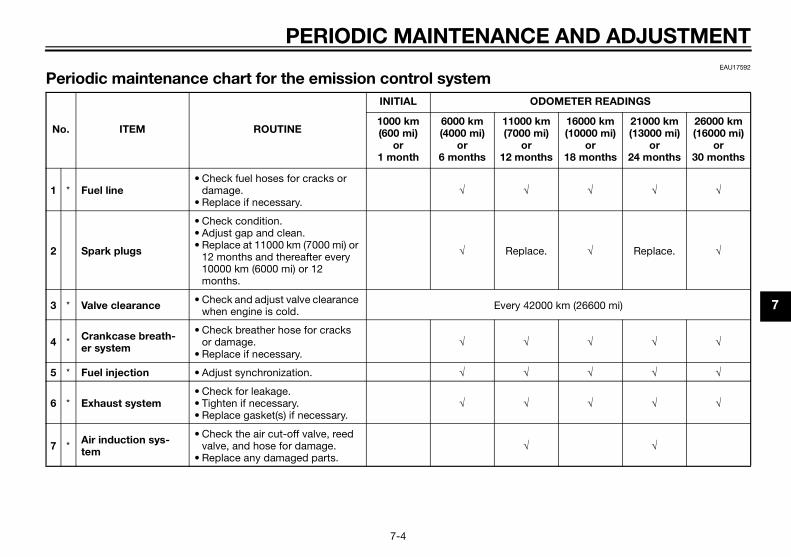
EAU17592
P
N
OMETER READINGS
m i)
hs
16000 km (10000 mi)
or 18 months
21000 km (13000 mi)
or 24 months
26000 km (16000 mi)
or 30 months
1 √ √ √
2 . √ Replace. √
3 00 km (26600 mi)
4 √ √ √
5 √ √ √
6 √ √ √
7 √
U2MS70E0.book Page 4 Thursday, December 18, 2014 1:46 PM
PERIODIC MAINTENANCE
7-4
eriodic maintenance chart for the emission control system
o. ITEM ROUTINE
INITIAL OD
1000 km (600 mi)
or 1 month
6000 km (4000 mi)
or 6 months
11000 k(7000 m
or 12 mont
* Fuel line• Check fuel hoses for cracks or
damage.• Replace if necessary.
√ √
Spark plugs
• Check condition.• Adjust gap and clean.• Replace at 11000 km (7000 mi) or
12 months and thereafter every 10000 km (6000 mi) or 12 months.
√ Replace
* Valve clearance• Check and adjust valve clearance
when engine is cold. Every 420
* Crankcase breath-er system
• Check breather hose for cracks or damage.
• Replace if necessary.√ √
* Fuel injection • Adjust synchronization. √ √
* Exhaust system• Check for leakage.• Tighten if necessary.• Replace gasket(s) if necessary.
√ √
* Air induction sys-tem
• Check the air cut-off valve, reed valve, and hose for damage.
• Replace any damaged parts.√
P
7
EAU32178
G
N
OMETER READINGS
)
s
16000 km (10000 mi)
or 18 months
21000 km (13000 mi)
or 24 months
26000 km (16000 mi)
or 30 months
1 √
2 √ √ √
3 √ √ √
4 √ √ √
5 √ √ √
6√ √ √
y 4 years
7 y 2 years
8 √ √ √
9 √ √ √
U2MS70E0.book Page 5 Thursday, December 18, 2014 1:46 PM
ERIODIC MAINTENANCE AND ADJUSTMENT
7-5
eneral maintenance and lubrication chart
o. ITEM ROUTINE
INITIAL OD
1000 km (600 mi)
or 1 month
6000 km (4000 mi)
or 6 months
11000 km(7000 mi
or 12 month
Air filter element • Replace.
Air filter check hose • Clean. √ √ √
* Clutch• Check operation.• Adjust or replace cable. √ √ √
* Front brake• Check operation, fluid level, and
for fluid leakage.• Replace brake pads if necessary.
√ √ √
* Rear brake• Check operation, fluid level, and
for fluid leakage.• Replace brake pads if necessary.
√ √ √
* Brake hose
• Check for cracks or damage.• Check for correct routing and
clamping.√ √
• Replace. Ever
* Brake fluid • Replace. Ever
* Wheels• Check runout and for damage.• Replace if necessary. √ √
* Tires
• Check tread depth and for dam-age.
• Replace if necessary.• Check air pressure.• Correct if necessary.
√ √

AND ADJUSTMENT
7
1 √ √ √
1 Repack.
1d after washing the motorcycle, or riding in wet areas
1 √ Repack. √
1 √ √ √
1 √ √ √
1 √ √ √
1 √ √ √
1 √ √ √
N
OMETER READINGS
m i)
hs
16000 km (10000 mi)
or 18 months
21000 km (13000 mi)
or 24 months
26000 km (16000 mi)
or 30 months
U2MS70E0.book Page 6 Thursday, December 18, 2014 1:46 PM
PERIODIC MAINTENANCE
7-6
0 * Wheel bearings• Check bearings for smooth oper-
ation.• Replace if necessary.
√ √
1 * Swingarm pivot bearings
• Check bearing assemblies for looseness.
• Moderately repack with lithium-soap-based grease.
√
2 Drive chain
• Check chain slack, alignment and condition.
• Adjust and lubricate chain with a special O-ring chain lubricant thoroughly.
Every 800 km (500 mi) anriding in the rain
3 * Steering bearings
• Check bearing assemblies for looseness.
• Moderately repack with lithium-soap-based grease.
√ √ √
4 * Chassis fasteners• Check all chassis fitting and fas-
teners.• Correct if necessary.
√ √
5Brake lever pivot shaft
• Apply silicone grease lightly. √ √
6Brake pedal pivot shaft
• Apply lithium-soap-based grease lightly. √ √
7Clutch lever pivot shaft
• Apply lithium-soap-based grease lightly. √ √
8Shift pedal pivot shaft
• Apply lithium-soap-based grease lightly. √ √
o. ITEM ROUTINE
INITIAL OD
1000 km (600 mi)
or 1 month
6000 km (4000 mi)
or 6 months
11000 k(7000 m
or 12 mont
P
7
19 √ √ √
20 √ √ √
21 √ √ √
22 √ √ √
23
oil change indicator flashes
√ √ √
24 √
25√ √ √
√
26 √ √ √
27 √ √ √
N
OMETER READINGS
)
s
16000 km (10000 mi)
or 18 months
21000 km (13000 mi)
or 24 months
26000 km (16000 mi)
or 30 months
U2MS70E0.book Page 7 Thursday, December 18, 2014 1:46 PM
ERIODIC MAINTENANCE AND ADJUSTMENT
7-7
Sidestand pivot• Check operation.• Apply lithium-soap-based grease
lightly.√ √
* Sidestand switch• Check operation and replace if
necessary. √ √ √
* Front fork• Check operation and for oil leak-
age.• Replace if necessary.
√ √
* Shock absorber as-sembly
• Check operation and for oil leak-age.
• Replace if necessary.√ √
Engine oil
• Change. (See pages 4-4 and 7-10.) √ When the
• Check oil level and vehicle for oil leakage. √ √ √
Engine oil filter car-tridge
• Replace. √ √
* Cooling system
• Check hoses for cracks or dam-age.
• Replace if necessary.√ √
• Change coolant.
* Front and rear brake switches
• Check operation. √ √ √
* Control cables• Apply Yamaha cable lubricant or
other suitable cable lubricant thoroughly.
√ √ √
o. ITEM ROUTINE
INITIAL OD
1000 km (600 mi)
or 1 month
6000 km (4000 mi)
or 6 months
11000 km(7000 mi
or 12 month

AND ADJUSTMENT
7
EAU17651
T
hich must not be cleaned with com-
ually wet or dusty areas.
fluid. Regularly check the brake fluid
and calipers, and change the brake
2 √ √ √
2 √ √ √
N
OMETER READINGS
m i)
hs
16000 km (10000 mi)
or 18 months
21000 km (13000 mi)
or 24 months
26000 km (16000 mi)
or 30 months
U2MS70E0.book Page 8 Thursday, December 18, 2014 1:46 PM
PERIODIC MAINTENANCE
7-8
IP
Air filter• This model’s air filter is equipped with a disposable oil-coated paper element, w
pressed air to avoid damaging it.• The air filter element needs to be replaced more frequently when riding in unus
Hydraulic brake service• After disassembling the brake master cylinders and calipers, always change the
levels and fill the reservoirs as required.• Every two years replace the internal components of the brake master cylinders
fluid.• Replace the brake hoses every four years and if cracked or damaged.
8 * Throttle grip
• Check operation.• Check throttle grip free play, and
adjust if necessary.• Lubricate cable and grip housing.
√ √
9 * Lights, signals and switches
• Check operation.• Adjust headlight beam. √ √ √
o. ITEM ROUTINE
INITIAL OD
1000 km (600 mi)
or 1 month
6000 km (4000 mi)
or 6 months
11000 k(7000 m
or 12 mont

P
7
CThcochYaitserchodchspthThceshidnoin cotinbeteyoerIf troot
torque wrench is not availableen installing a spark plug, a goodimate of the correct torque is 1/4– turn past finger tight. However, therk plug should be tightened to thecified torque as soon as possible.
U2MS70E0.book Page 9 Thursday, December 18, 2014 1:46 PM
ERIODIC MAINTENANCE AND ADJUSTMENT
7-9
EAU19643
hecking the spark plugse spark plugs are important enginemponents, which should beecked periodically, preferably by amaha dealer. Since heat and depos- will cause any spark plug to slowlyode, they should be removed andecked in accordance with the peri-ic maintenance and lubricationart. In addition, the condition of theark plugs can reveal the condition ofe engine.e porcelain insulator around thenter electrode of each spark plugould be a medium-to-light tan (theeal color when the vehicle is riddenrmally), and all spark plugs installedthe engine should have the samelor. If any spark plug shows a dis-ctly different color, the engine could operating improperly. Do not at-mpt to diagnose such problemsurself. Instead, have a Yamaha deal- check the vehicle.a spark plug shows signs of elec-de erosion and excessive carbon or
her deposits, it should be replaced.
Before installing a spark plug, thespark plug gap should be measuredwith a wire thickness gauge and, ifnecessary, adjusted to specification.
Clean the surface of the spark pluggasket and its mating surface, andthen wipe off any grime from the sparkplug threads.
TIP
If awhest1/2spaspe
Specified spark plug:NGK/CR8E
1. Spark plug gap
Spark plug gap:0.7–0.8 mm (0.028–0.031 in)
Tightening torque:Spark plug:
13 Nm (1.3 m·kgf, 9.4 ft·lbf)

AND ADJUSTMENT
7
EtrTbmtrfilu
T
T
Tm
. Remove the engine oil filler cap,the engine oil drain bolt and itsgasket to drain the oil from thecrankcase.
ip steps 5–7 if the oil filter cartridgeot being replaced.
. Remove the oil filter cartridge withan oil filter wrench.
ngine oil drain boltasket
21
U2MS70E0.book Page 10 Thursday, December 18, 2014 1:46 PM
PERIODIC MAINTENANCE
7-10
EAU62632
ngine oil and oil filter car-idge
he engine oil level should be checkedefore each ride. In addition, the oilust be changed and the oil filter car-idge replaced at the intervals speci-ed in the periodic maintenance andbrication chart.
o check the engine oil level
1. Place the vehicle on a level sur-face and hold it in an upright posi-tion. A slight tilt to the side canresult in a false reading.
2. Start the engine, warm it up forseveral minutes, and then turn itoff.
3. Wait a few minutes until the oil set-tles, and then check the oil levelthrough the engine oil level checkwindow located at the bottom-right side of the crankcase.
IP
he engine oil should be between theinimum and maximum level marks.
4. If the engine oil is below the mini-mum level mark, add sufficient oilof the recommended type to raiseit to the correct level.
To change the engine oil (with or
without oil filter cartridge replace-
ment)
1. Place the vehicle on a level sur-face.
2. Start the engine, warm it up forseveral minutes, and then turn itoff.
3. Place an oil pan under the engineto collect the used oil.
4
TIP
Skis n
5
1. Engine oil filler cap2. Engine oil level check window3. Maximum level mark4. Minimum level mark
42
13
1. E2. G

P
7
TI
AnYa
6Install the engine oil drain bolt andits new gasket, and then tightenthe bolt to the specified torque.
tall the new gasket as shown.
1.2.
orque wrench
ightening torque:Oil filter cartridge:
17 Nm (1.7 m·kgf, 12 ft·lbf)
1
U2MS70E0.book Page 11 Thursday, December 18, 2014 1:46 PM
ERIODIC MAINTENANCE AND ADJUSTMENT
7-11
P
oil filter wrench is available at amaha dealer.
. Apply a thin coat of clean engineoil to the O-ring of the new oil filtercartridge.
TIP
Make sure that the O-ring is properlyseated.
7. Install the new oil filter cartridgewith an oil filter wrench, and thentighten it to the specified torquewith a torque wrench.
8.
TIP
Ins
Oil filter wrenchOil filter cartridge
1 2
1. O-ring 1. T
T

AND ADJUSTMENT
7
TICEECA20860
he oil pressure warning light flick-
or remains on even if the oil level
correct, immediately turn the en-
e off and have a Yamaha dealer
eck the vehicle.
. Turn the engine off, wait a fewminutes until the oil settles, andthen check the oil level and cor-rect it if necessary.
1.2.
U2MS70E0.book Page 12 Thursday, December 18, 2014 1:46 PM
PERIODIC MAINTENANCE
7-12
9. Refill with the specified amount ofthe recommended engine oil, andthen install and tighten the oil fillercap.
TIP
Be sure to wipe off spilled oil on anyparts after the engine and exhaust sys-tem have cooled down.
NOTICEECA11621
In order to prevent clutch slip-
page (since the engine oil also
lubricates the clutch), do not
mix any chemical additives. Do
not use oils with a diesel speci-
fication of “CD” or oils of a high-
er quality than specified. In
addition, do not use oils labeled
“ENERGY CONSERVING II” or
higher.
Make sure that no foreign mate-
rial enters the crankcase.
10. Start the engine, and then let it idlefor several minutes while checkingit for oil leakage. If oil is leaking,immediately turn the engine offand check for the cause.
TIP
After the engine is started, the engineoil pressure warning light should go off.
NO
If t
ers
is
gin
ch
11
Engine oil drain boltGasket
Tightening torque:Engine oil drain bolt:
20 Nm (2.0 m·kgf, 14 ft·lbf)
Recommended engine oil:See page 9-1.
Oil quantity:Without oil filter cartridge replace-ment:
1.80 L (1.90 US qt, 1.58 Imp.qt)With oil filter cartridge replacement:
2.10 L (2.22 US qt, 1.85 Imp.qt)
2
1

P
7
CThbeanspan
To
1
TI
2
TI
Thm
Remove the coolant reservoir cap,add coolant to the maximum levelmark, and then install the reservoircap. WARNING! Remove only
the coolant reservoir cap. Never
attempt to remove the radiator
cap when the engine is hot.
[EWA15162] NOTICE: If coolant is not
available, use distilled water or
soft tap water instead. Do not
use hard water or salt water
since it is harmful to the engine.
If water has been used instead
of coolant, replace it with cool-
ant as soon as possible, other-
wise the cooling system will not
be protected against frost and
oltoolant reservoir cover
2
1
U2MS70E0.book Page 13 Thursday, December 18, 2014 1:46 PM
ERIODIC MAINTENANCE AND ADJUSTMENT
7-13
EAU20071
oolante coolant level should be checkedfore each ride. In addition, the cool-t must be changed at the intervalsecified in the periodic maintenanced lubrication chart.
EAUN0690
check the coolant level
. Place the vehicle on a level sur-face and hold it in an upright posi-tion.
P
The coolant level must bechecked on a cold engine sincethe level varies with engine tem-perature.Make sure that the vehicle is posi-tioned straight up when checkingthe coolant level. A slight tilt to theside can result in a false reading.
. Check the coolant level in thecoolant reservoir.
P
e coolant should be between theinimum and maximum level marks.
3. If the coolant is at or below theminimum level mark, remove theleft side cowling and coolant res-ervoir cover to access the coolantreservoir.
4.
1. Maximum level mark2. Minimum level mark3. Coolant reservoir
1. Left side cowling2. Bolt
1
2
3
2
1
2
2
1. B2. C

AND ADJUSTMENT
7
T
Fth
EAU62650
placing the air filter ele-ent and cleaning the check se
e air filter element should be re-ced at the intervals specified in theriodic maintenance and lubricationart. Replace the air filter elementre frequently if you are riding in un-
ually wet or dusty areas. In addition, air filter check hose must be fre-ently checked and cleaned if neces-y.
replace the air filter element
. Remove the left side panel by re-moving the bolts.1.
eft side panelolt
22
1
U2MS70E0.book Page 14 Thursday, December 18, 2014 1:46 PM
PERIODIC MAINTENANCE
7-14
corrosion. If water has been
added to the coolant, have a
Yamaha dealer check the anti-
freeze content of the coolant as
soon as possible, otherwise the
effectiveness of the coolant will
be reduced. [ECA10473]
5. Install the coolant reservoir cover.6. Install the left side cowling by in-
stalling the bolts.
IP
it the projections on the cowling intoe slots as shown.
EAU33032
Changing the coolant
The coolant must be changed at the in-tervals specified in the periodic main-tenance and lubrication chart. Have aYamaha dealer change the coolant.WARNING! Never attempt to remove
the radiator cap when the engine is
hot. [EWA10382]
RemhoThplapechmousthequsar
To
1
Coolant reservoir cap
Coolant reservoir capacity (up to the maximum level mark):
0.25 L (0.26 US qt, 0.22 Imp.qt)
1
1. Slot2. Projection3. Left side cowling
3
1 22 1
1. L2. B
P
7
2
3
4
If dirt or water is visible, removethe hose, clean it, and then installit.
1.2.
1.
U2MS70E0.book Page 15 Thursday, December 18, 2014 1:46 PM
ERIODIC MAINTENANCE AND ADJUSTMENT
7-15
. Remove the air filter case cover byremoving the screws.
. Pull the air filter element out.
. Insert a new air filter element intothe air filter case. NOTICE: Make
sure that the air filter element is
properly seated in the air filter
case. The engine should never
be operated without the air filter
element installed, otherwise the
piston(s) and/or cylinder(s) may
become excessively worn.
[ECA10482]
5. Install the air filter case cover byinstalling the screws.
6. Install the left side panel by install-ing the bolts.
To clean the air filter check hose
1. Check the hose on the front of theair filter case for accumulated dirtor water.
2.
Air filter case coverScrew
Air filter element
1
22
1
1. Air filter check hose
1

AND ADJUSTMENT
7
Cp
Tsuincae
EAU62030
eses are the only contact between thehicle and the road. Safety in all con-ions of riding depends on a relativelyall area of road contact. Therefore, itssential to maintain the tires in good
ndition at all times and replace themthe appropriate time with the speci- tires.
e air pressure
e tire air pressure should beecked and, if necessary, adjustedfore each ride.
WARNING
EWA10504
eration of this vehicle with im-
per tire pressure may cause se-
re injury or death from loss of
ntrol.
The tire air pressure must be
checked and adjusted on cold
tires (i.e., when the temperature
of the tires equals the ambient
temperature).
The tire air pressure must be
adjusted in accordance with the
riding speed and with the total
1.
U2MS70E0.book Page 16 Thursday, December 18, 2014 1:46 PM
PERIODIC MAINTENANCE
7-16
EAU21385
hecking the throttle grip free lay
he throttle grip free play should mea-re 3.0–5.0 mm (0.12–0.20 in) at the
ner edge of the throttle grip. Periodi-ally check the throttle grip free playnd, if necessary, have a Yamaha deal-r adjust it.
EAU21402
Valve clearanceThe valve clearance changes with use,resulting in improper air-fuel mixtureand/or engine noise. To prevent thisfrom occurring, the valve clearancemust be adjusted by a Yamaha dealerat the intervals specified in the periodicmaintenance and lubrication chart.
TirTirveditsmis ecoat fied
Tir
Thchbe
Op
pro
ve
co
Throttle grip free play
1

P
7
Ne
tio
ca
WARNING
EWA10472
Have a Yamaha dealer replace
excessively worn tires. Besides
being illegal, operating the vehi-
cle with excessively worn tires
decreases riding stability and
can lead to loss of control.
The replacement of all wheel
and brake-related parts, includ-
ing the tires, should be left to a
Yamaha dealer, who has the
necessary professional knowl-
edge and experience to do so.
Ride at moderate speeds after
changing a tire since the tire
surface must first be “broken
in” for it to develop its optimal
characteristics.
information
s model is equipped with tubelesss and tire air valves.s age, even if they have not beend or have only been used occasion-. Cracking of the tread and sidewallber, sometimes accompanied bycass deformation, is an evidence of
U2MS70E0.book Page 17 Thursday, December 18, 2014 1:46 PM
ERIODIC MAINTENANCE AND ADJUSTMENT
7-17
weight of rider, passenger, car-
go, and accessories approved
for this model.
WARNING
EWA10512
ver overload your vehicle. Opera-
n of an overloaded vehicle could
use an accident.
Tire inspection
The tires must be checked before eachride. If the center tread depth reachesthe specified limit, if the tire has a nailor glass fragments in it, or if the side-wall is cracked, have a Yamaha dealerreplace the tire immediately.
TIP
The tire tread depth limit may differfrom province to province. Alwayscomply with the local regulations.
Tire
ThitireTireuseallyrubcar
Tire air pressure (measured on cold tires):
Up to 90 kg (198 lb) load:Front:
200 kPa (2.00 kgf/cm2, 29 psi)Rear:
250 kPa (2.50 kgf/cm2, 36 psi)90 kg (198 lb) to maximum load:
Front:200 kPa (2.00 kgf/cm2, 29 psi)
Rear:250 kPa (2.50 kgf/cm2, 36 psi)
Maximum load*:160 kg (353 lb)
* Total weight of rider, passenger, car-go and accessories
1. Tire sidewall2. Tire tread depth
Minimum tire tread depth (front and rear):
1.0 mm (0.04 in)

AND ADJUSTMENT
7
acth
T
th
w
th
c
Aem
EAU62662
justing the clutch lever free y
e clutch lever free play should mea-re 10.0–15.0 mm (0.39–0.59 in) asown. Periodically check the clutcher free play and, if necessary, adjusts follows.. Loosen the locknut at the clutch
lever.. To increase the clutch lever free
play, turn the clutch lever free playadjusting bolt in direction (a). Todecrease the clutch lever freeplay, turn the adjusting bolt in di-rection (b).
lutch lever free play adjusting boltocknutlutch lever free play
2 1
(a)
(b)
U2MS70E0.book Page 18 Thursday, December 18, 2014 1:46 PM
PERIODIC MAINTENANCE
7-18
geing. Old and aged tires shall behecked by tire specialists to ascertaineir suitability for further use.
WARNING
EWA10462
he front and rear tires should be of
e same make and design, other-
ise the handling characteristics of
e vehicle may be different, which
ould lead to an accident.
fter extensive tests, only the tires list-d below have been approved for thisodel by Yamaha.
EAU21963
Cast wheelsTo maximize the performance, durabil-ity, and safe operation of your vehicle,note the following points regarding thespecified wheels. The wheel rims should be
checked for cracks, bends, warp-age or other damage before eachride. If any damage is found, havea Yamaha dealer replace thewheel. Do not attempt even thesmallest repair to the wheel. A de-formed or cracked wheel must bereplaced.
The wheel should be balancedwhenever either the tire or wheelhas been changed or replaced. Anunbalanced wheel can result inpoor performance, adverse han-dling characteristics, and a short-ened tire life.
Adpla
Thsushlevit a
1
2
Front tire:Size:
110/70-17M/C (54H)Manufacturer/model:
MICHELIN/PILOT STREETRear tire:
Size:140/70-17M/C (66H)
Manufacturer/model:MICHELIN/PILOT STREET
1. C2. L3. C
3

P
7
TI
If cosk
3
4
5
6
Tighten the locknut at the clutchlever.
1.2.
lotrojectionight side cowling
3
12
2
1
U2MS70E0.book Page 19 Thursday, December 18, 2014 1:46 PM
ERIODIC MAINTENANCE AND ADJUSTMENT
7-19
P
the specified clutch lever free playuld be obtained as described above,ip steps 3–8.
. Fully turn the adjusting bolt at theclutch lever in direction (a) to loos-en the clutch cable.
. Remove the right side cowling byremoving the bolts.
. Loosen the locknut at the crank-case.
. To increase the clutch lever freeplay, turn the clutch lever free playadjusting nut in direction (a). To
decrease the clutch lever freeplay, turn the adjusting nut in di-rection (b).
7. Tighten the locknut at the crank-case.
8. Install the right side cowling by in-stalling the bolts.
TIP
Fit the projections on the cowling intothe slots as shown.
9.
Right side cowlingBolt
2
1
2
21. Locknut2. Clutch lever free play adjusting nut
2(b)
(a)
1
1. S2. P3. R

AND ADJUSTMENT
7
Cp
Tbhb
A
le
a
a
Y
fo
h
EAU22274
ake light switches
e brake light, which is activated by brake pedal and brake lever,
ould come on just before brakinges effect. If necessary, adjust ther brake light switch as follows, but front brake light switch should bejusted by a Yamaha dealer.rn the rear brake light switch adjust- nut while holding the rear braket switch in place. To make theke light come on earlier, turn the ad-ting nut in direction (a). To make theke light come on later, turn the ad-ting nut in direction (b).
1.
ear brake light switchear brake light switch adjusting nut
2
1
(a) (b)
U2MS70E0.book Page 20 Thursday, December 18, 2014 1:46 PM
PERIODIC MAINTENANCE
7-20
EAU37914
hecking the brake lever free lay
here should be no free play at therake lever end. If there is free play,ave a Yamaha dealer inspect therake system.
WARNING
EWA14212
soft or spongy feeling in the brake
ver can indicate the presence of
ir in the hydraulic system. If there is
ir in the hydraulic system, have a
amaha dealer bleed the system be-
re operating the vehicle. Air in the
ydraulic system will diminish the
braking performance, which may re-
sult in loss of control and an acci-
dent.
Br
ThtheshtakreatheadTuinglighbrajusbrajus
No brake lever free play
1
1. R2. R

P
7
CbrThchifielub
Fr
EaweyoouTothpa
EAU22582
ecking the brake fluid levelore riding, check that the brake fluidabove the minimum level mark.ck the brake fluid level with the top
the reservoir level. Replenish theke fluid if necessary.
nt brake
1.
inimum level mark
U2MS70E0.book Page 21 Thursday, December 18, 2014 1:46 PM
ERIODIC MAINTENANCE AND ADJUSTMENT
7-21
EAU22393
hecking the front and rear ake padse front and rear brake pads must beecked for wear at the intervals spec-d in the periodic maintenance andrication chart.
EAU22432
ont brake pads
ch front brake pad is provided withar indicator grooves, which allowu to check the brake pad wear with-t having to disassemble the brake. check the brake pad wear, check
e wear indicator grooves. If a braked has worn to the point that the wear
indicator grooves have almost disap-peared, have a Yamaha dealer replacethe brake pads as a set.
EAU36721
Rear brake pads
Each rear brake pad is provided withwear indicator grooves, which allowyou to check the brake pad wear with-out having to disassemble the brake.To check the brake pad wear, checkthe wear indicator grooves. If a brakepad has worn to the point that the wearindicator grooves have almost disap-peared, have a Yamaha dealer replacethe brake pads as a set.
ChBefis Cheof bra
Fro
Brake pad wear indicator groove
11
1. Brake pad wear indicator groove
11
1. M
1
AND ADJUSTMENT
7
R
Im
lo
th
id level goes down suddenly, have amaha dealer check the cause beforether riding.
1.
U2MS70E0.book Page 22 Thursday, December 18, 2014 1:46 PM
PERIODIC MAINTENANCE
7-22
ear brake
WARNING
EWA15991
proper maintenance can result in
ss of braking ability. Observe
ese precautions:
Insufficient brake fluid may al-
low air to enter the brake sys-
tem, reducing braking
performance.
Clean the filler cap before re-
moving. Use only DOT 4 brake
fluid from a sealed container.
Use only the specified brake flu-
id; otherwise, the rubber seals
may deteriorate, causing leak-
age.
Refill with the same type of
brake fluid. Adding a brake fluid
other than DOT 4 may result in a
harmful chemical reaction.
Be careful that water does not
enter the brake fluid reservoir
when refilling. Water will signifi-
cantly lower the boiling point of
the fluid and may result in vapor
lock.
NOTICEECA17641
Brake fluid may damage painted
surfaces or plastic parts. Always
clean up spilled fluid immediately.
As the brake pads wear, it is normal forthe brake fluid level to gradually godown. A low brake fluid level may indi-cate worn brake pads and/or brakesystem leakage; therefore, be sure tocheck the brake pads for wear and thebrake system for leakage. If the brake
fluYafur
Minimum level mark
Specified brake fluid:DOT 4
1

P
7
CHabrthtioofweintar
If the drive chain slack is incorrect,adjust it as follows.
EAU62980
adjust the drive chain slack
sult a Yamaha dealer before ad-ing the drive chain slack.Remove the drive chain puller cap,and then loosen the axle nut andthe locknut on each side of theswingarm.
rive chain slack
1
U2MS70E0.book Page 23 Thursday, December 18, 2014 1:46 PM
ERIODIC MAINTENANCE AND ADJUSTMENT
7-23
EAU22733
hanging the brake fluidve a Yamaha dealer change the
ake fluid at the intervals specified ine periodic maintenance and lubrica-n chart. In addition, have the oil seals the master cylinders and calipers asll as the brake hoses replaced at theervals listed below or whenever theye damaged or leaking.
Oil seals: Replace every twoyears.Brake hoses: Replace every fouryears.
EAU22762
Drive chain slackThe drive chain slack should bechecked before each ride and adjustedif necessary.
EAU22776
To check the drive chain slack
1. Place the motorcycle on the side-stand.
TIP
When checking and adjusting the drivechain slack, there should be no weighton the motorcycle.
2. Shift the transmission into theneutral position.
3. Measure the drive chain slack asshown.
4.
To
Conjust
1.
Drive chain slack:35.0–45.0 mm (1.38–1.77 in)
1. D
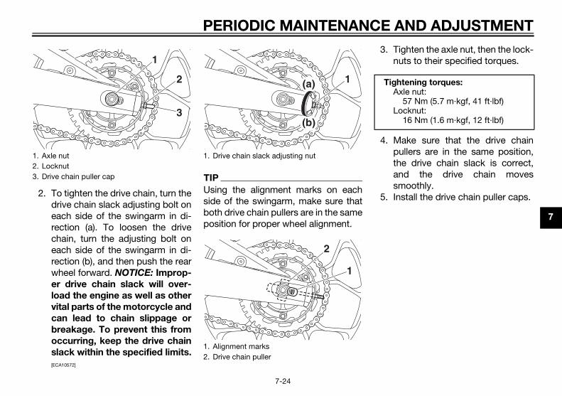
AND ADJUSTMENT
7
. Tighten the axle nut, then the lock-nuts to their specified torques.
. Make sure that the drive chainpullers are in the same position,the drive chain slack is correct,and the drive chain movessmoothly.
. Install the drive chain puller caps.
1.2.3.
ightening torques:Axle nut:
57 Nm (5.7 m·kgf, 41 ft·lbf)Locknut:
16 Nm (1.6 m·kgf, 12 ft·lbf)
U2MS70E0.book Page 24 Thursday, December 18, 2014 1:46 PM
PERIODIC MAINTENANCE
7-24
2. To tighten the drive chain, turn thedrive chain slack adjusting bolt oneach side of the swingarm in di-rection (a). To loosen the drivechain, turn the adjusting bolt oneach side of the swingarm in di-rection (b), and then push the rearwheel forward. NOTICE: Improp-
er drive chain slack will over-
load the engine as well as other
vital parts of the motorcycle and
can lead to chain slippage or
breakage. To prevent this from
occurring, keep the drive chain
slack within the specified limits.
[ECA10572]
TIP
Using the alignment marks on eachside of the swingarm, make sure thatboth drive chain pullers are in the sameposition for proper wheel alignment.
3
4
5
Axle nutLocknutDrive chain puller cap
2
1
3
1. Drive chain slack adjusting nut
1. Alignment marks2. Drive chain puller
1(a)
(b)
1
2
T

P
7
CdrThlubthtioouwefo
N
Th
af
in
1
23
EAU23098
ecking and lubricating the bles operation of all control cables and condition of the cables should becked before each ride, and the ca-s and cable ends should be lubri-ed if necessary. If a cable is
aged or does not move smoothly,e a Yamaha dealer check or re-ce it. WARNING! Damage to the
er housing of cables may result
nternal rusting and cause inter-
nce with cable movement. Re-
ce damaged cables as soon as
sible to prevent unsafe condi-
s. [EWA10712]
ecommended lubricant:Yamaha cable lubricant or other suitable cable lubricant
U2MS70E0.book Page 25 Thursday, December 18, 2014 1:46 PM
ERIODIC MAINTENANCE AND ADJUSTMENT
7-25
EAU23026
leaning and lubricating the ive chaine drive chain must be cleaned andricated at the intervals specified in
e periodic maintenance and lubrica-n chart, otherwise it will quickly weart, especially when riding in dusty ort areas. Service the drive chain as
llows.
OTICEECA10584
e drive chain must be lubricated
ter washing the motorcycle, riding
the rain or riding in wet areas.
. Clean the drive chain with kero-sene and a small soft brush.NOTICE: To prevent damaging
the O-rings, do not clean the
drive chain with steam cleaners,
high-pressure washers or inap-
propriate solvents. [ECA11122]
. Wipe the drive chain dry.
. Thoroughly lubricate the drivechain with a special O-ring chainlubricant. NOTICE: Do not use
engine oil or any other lubri-
cants for the drive chain, as they
may contain substances that
could damage the O-rings.
[ECA11112]
ChcaThethecheblecatdamhavplaout
in i
fere
pla
pos
tion
R

AND ADJUSTMENT
7
CthTshaespc
ecommended lubricant:Lithium-soap-based grease
U2MS70E0.book Page 26 Thursday, December 18, 2014 1:46 PM
PERIODIC MAINTENANCE
7-26
EAU49921
hecking and lubricating the rottle grip and cable
he operation of the throttle gripould be checked before each ride. In
ddition, the cable should be lubricat-d by a Yamaha dealer at the intervalsecified in the periodic maintenance
hart.
EAU44275
Checking and lubricating the brake and shift pedalsThe operation of the brake and shiftpedals should be checked before eachride, and the pedal pivots should be lu-bricated if necessary.
Brake pedal
Shift pedal
R

P
7
CbrThlevridbr
Br
Cl
EAU23203
ecking and lubricating the estand
operation of the sidestand shouldchecked before each ride, and thestand pivot and metal-to-metaltact surfaces should be lubricated
ecessary.
WARNING
EWA10732
he sidestand does not move up
down smoothly, have a Yamaha
ler check or repair it. Otherwise,
sidestand could contact the
und and distract the operator, re-
ting in a possible loss of control.
ecommended lubricant:Lithium-soap-based grease
U2MS70E0.book Page 27 Thursday, December 18, 2014 1:46 PM
ERIODIC MAINTENANCE AND ADJUSTMENT
7-27
EAU23144
hecking and lubricating the ake and clutch leverse operation of the brake and clutchers should be checked before eache, and the lever pivots should be lu-icated if necessary.
ake lever
utch lever
Chsid
Thebe sideconif n
If t
and
dea
the
gro
sul
Recommended lubricants:Brake lever:
Silicone greaseClutch lever:
Lithium-soap-based grease
R
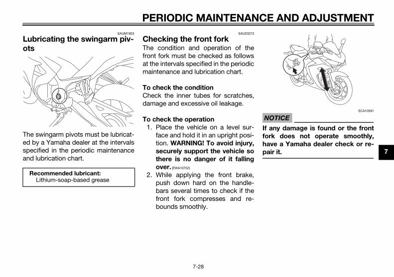
AND ADJUSTMENT
7
Lo
Tespa
TICEECA10591
ny damage is found or the front
k does not operate smoothly,
ve a Yamaha dealer check or re-
ir it.
U2MS70E0.book Page 28 Thursday, December 18, 2014 1:46 PM
PERIODIC MAINTENANCE
7-28
EAUM1653
ubricating the swingarm piv-ts
he swingarm pivots must be lubricat-d by a Yamaha dealer at the intervalsecified in the periodic maintenance
nd lubrication chart.
EAU23273
Checking the front forkThe condition and operation of thefront fork must be checked as followsat the intervals specified in the periodicmaintenance and lubrication chart.
To check the condition
Check the inner tubes for scratches,damage and excessive oil leakage.
To check the operation
1. Place the vehicle on a level sur-face and hold it in an upright posi-tion. WARNING! To avoid injury,
securely support the vehicle so
there is no danger of it falling
over. [EWA10752]
2. While applying the front brake,push down hard on the handle-bars several times to check if thefront fork compresses and re-bounds smoothly.
NO
If a
for
ha
pa
Recommended lubricant:Lithium-soap-based grease

P
7
CWcaoflowpech
1
2
EAU62521
ttery
battery is located under the ridert. (See page 4-16.)s model is equipped with a VRLAlve Regulated Lead Acid) battery.re is no need to check the electro- or to add distilled water. However, battery lead connections need tochecked and, if necessary, tight-d.
WARNING
EWA10761
Electrolyte is poisonous and
dangerous since it contains sul-
furic acid, which causes severe
atteryegative battery lead (black)ositive battery lead (red)
1
2
3
U2MS70E0.book Page 29 Thursday, December 18, 2014 1:46 PM
ERIODIC MAINTENANCE AND ADJUSTMENT
7-29
EAU23285
hecking the steeringorn or loose steering bearings mayuse danger. Therefore, the operation the steering must be checked as fol-
s at the intervals specified in theriodic maintenance and lubricationart.. Raise the front wheel off the
ground. (See page 7-36.)WARNING! To avoid injury, se-
curely support the vehicle so
there is no danger of it falling
over. [EWA10752]
. Hold the lower ends of the frontfork legs and try to move them for-ward and backward. If any freeplay can be felt, have a Yamahadealer check or repair the steer-ing.
EAU23292
Checking the wheel bearings
The front and rear wheel bearings mustbe checked at the intervals specified inthe periodic maintenance and lubrica-tion chart. If there is play in the wheelhub or if the wheel does not turnsmoothly, have a Yamaha dealercheck the wheel bearings.
Ba
TheseaThi(VaThelytethebe ene
1. B2. N3. P

AND ADJUSTMENT
7
turned to “ ”, then disconnect
the negative lead before discon-
necting the positive lead. [ECA17712]
. If the battery will be stored formore than two months, check it atleast once a month and fullycharge it if necessary.
. Fully charge the battery before in-stallation. NOTICE: When install-
ing the battery, be sure the key
is turned to “ ”, then connect
the positive lead before con-
necting the negative lead. [ECA17722]
. After installation, make sure thatthe battery leads are properly con-nected to the battery terminals.
TICEECA16531
ays keep the battery charged.
ring a discharged battery can
use permanent battery damage.
U2MS70E0.book Page 30 Thursday, December 18, 2014 1:46 PM
PERIODIC MAINTENANCE
7-30
burns. Avoid any contact with
skin, eyes or clothing and al-
ways shield your eyes when
working near batteries. In case
of contact, administer the fol-
lowing FIRST AID.
• EXTERNAL: Flush with plenty
of water.
• INTERNAL: Drink large quan-
tities of water or milk and im-
mediately call a physician.
• EYES: Flush with water for 15
minutes and seek prompt
medical attention.
Batteries produce explosive hy-
drogen gas. Therefore, keep
sparks, flames, cigarettes, etc.,
away from the battery and pro-
vide sufficient ventilation when
charging it in an enclosed
space.
KEEP THIS AND ALL BATTER-
IES OUT OF THE REACH OF
CHILDREN.
NOTICEECA10621
Never attempt to remove the battery
cell seals, as this would permanently
damage the battery.
To charge the battery
Have a Yamaha dealer charge the bat-tery as soon as possible if it seems tohave discharged. Keep in mind that thebattery tends to discharge more quick-ly if the vehicle is equipped with op-tional electrical accessories.
NOTICEECA16522
To charge a VRLA (Valve Regulated
Lead Acid) battery, a special (con-
stant-voltage) battery charger is re-
quired. Using a conventional battery
charger will damage the battery.
To store the battery
1. If the vehicle will not be used formore than one month, remove thebattery, fully charge it, and thenplace it in a cool, dry place.NOTICE: When removing the
battery, be sure the key is
2
3
4
NO
Alw
Sto
ca

P
7
RThpacocuel.Tofo
1
2
3
fuse is blown, replace it as follows.
1.2.
use box
nition fuseignaling system fuseackup fuse (for clock)eadlight fuseadiator fan motor fusepare fuse
1
2
3
4
5
U2MS70E0.book Page 31 Thursday, December 18, 2014 1:46 PM
ERIODIC MAINTENANCE AND ADJUSTMENT
7-31
EAU62772
eplacing the fusese main fuse is located under thessenger seat. The fuse box, whichntains the fuses for the individual cir-its, is located behind the center pan- (See page 4-16.) access the main fuse, proceed as
llows.. Remove the passenger seat. (See
page 4-16.). Remove the tray by removing the
quick fasteners.
. Pull back the starter relay cover,and then disconnect the starter re-lay coupler as shown.
4. Connect the starter relay coupler,and then slide the cover to its orig-inal position.
5. Place the tray in its original posi-tion, and then install the quick fas-teners.
6. Install the passenger seat.
TIP
To access the fuse box, remove thecenter cover.(See page 4-16.)
If a
Quick fastenerTray
2
1
1. Starter relay cover2. Starter relay coupler3. Main fuse4. Spare main fuse
1
2
3
4
1. F
1. Ig2. S3. B4. H5. R6. S
1
6

AND ADJUSTMENT
7
. Remove the headlight bulb coverby turning it counterclockwise.
. Disconnect the headlight coupler.
o not touch the glass part of the bulb.
eadlight bulb cover
U2MS70E0.book Page 32 Thursday, December 18, 2014 1:46 PM
PERIODIC MAINTENANCE
7-32
1. Turn the key to “ ” and turn offthe electrical circuit in question.
2. Remove the blown fuse, and theninstall a new fuse of the specifiedamperage. WARNING! Do not
use a fuse of a higher amperage
rating than recommended to
avoid causing extensive dam-
age to the electrical system and
possibly a fire. [EWA15132]
3. Turn the key to “ ” and turn onthe electrical circuit in question tocheck if the device operates.
4. If the fuse immediately blowsagain, have a Yamaha dealercheck the electrical system.
EAU39014
Replacing a headlight bulbThis model is equipped with halogenbulb headlights. If a headlight bulbburns out, replace it as follows.
NOTICEECA10651
Take care not to damage the follow-
ing parts:
Headlight bulb
Do not touch the glass part of
the headlight bulb to keep it free
from oil, otherwise the transpar-
ency of the glass, the luminosity
of the bulb, and the bulb life will
be adversely affected. Thor-
oughly clean off any dirt and fin-
gerprints on the headlight bulb
using a cloth moistened with al-
cohol or thinner.
Headlight lens
Do not affix any type of tinted
film or stickers to the headlight
lens.
Do not use a headlight bulb of a
wattage higher than specified.
1
2
Specified fuses:Main fuse:
30.0 AHeadlight fuse:
15.0 ASignaling system fuse:
15.0 AIgnition fuse:
15.0 ARadiator fan motor fuse:
7.5 ABackup fuse:
7.5 A
1. D
1. H
1

P
7
3
4
5
EAU39021
xiliary light bulb
e auxiliary light does not come on,e a Yamaha dealer check the elec-al circuit or replace the bulb.
1.
1.
uxiliary light
U2MS70E0.book Page 33 Thursday, December 18, 2014 1:46 PM
ERIODIC MAINTENANCE AND ADJUSTMENT
7-33
. Unhook the headlight bulb holder,and then remove the burnt-outbulb.
. Place a new headlight bulb intoposition, and then secure it withthe bulb holder.
. Connect the headlight coupler.
6. Install the headlight bulb cover byturning it clockwise.
7. Have a Yamaha dealer adjust theheadlight beam if necessary.
Au
If thhavtric
Headlight coupler
Headlight bulb holder
1
1
1. A
1
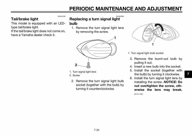
AND ADJUSTMENT
7
TTtyIfh
. Remove the burnt-out bulb bypulling it out.
. Insert a new bulb into the socket.
. Install the socket (together withthe bulb) by turning it clockwise.
. Install the turn signal light lens byinstalling the screw. NOTICE: Do
not overtighten the screw, oth-
erwise the lens may break.
[ECA11192]
urn signal light bulb socket
1
U2MS70E0.book Page 34 Thursday, December 18, 2014 1:46 PM
PERIODIC MAINTENANCE
7-34
EAU24182
ail/brake lighthis model is equipped with an LED-pe tail/brake light. the tail/brake light does not come on,ave a Yamaha dealer check it.
EAU62590
Replacing a turn signal light bulb
1. Remove the turn signal light lensby removing the screw.
2. Remove the turn signal light bulbsocket (together with the bulb) byturning it counterclockwise.
3
45
6
1. Turn signal light lens2. Screw
1
2
1. T
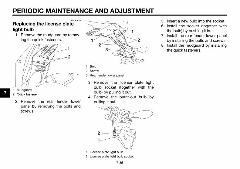
P
7
Rlig
1
2
Insert a new bulb into the socket.Install the socket (together withthe bulb) by pushing it in.Install the rear fender lower panelby installing the bolts and screws.Install the mudguard by installingthe quick fasteners.
1.2.
U2MS70E0.book Page 35 Thursday, December 18, 2014 1:46 PM
ERIODIC MAINTENANCE AND ADJUSTMENT
7-35
EAU62670
eplacing the license plate ht bulb. Remove the mudguard by remov-
ing the quick fasteners.
. Remove the rear fender lowerpanel by removing the bolts andscrews.
3. Remove the license plate lightbulb socket (together with thebulb) by pulling it out.
4. Remove the burnt-out bulb bypulling it out.
5.6.
7.
8.
MudguardQuick fastener
1
2
1. Bolt2. Screw3. Rear fender lower panel
1. License plate light bulb2. License plate light bulb socket
3
2
1
22
1
2
1

AND ADJUSTMENT
7
SScwwnstcfostd
T
T
Ruc
EAU24361
ont wheel
EAUN0670
remove the front wheel
WARNING
EWA10822
avoid injury, securely support the
hicle so there is no danger of it
ling over.
. Loosen the axle nut and the brakecaliper bolts.
xle nut
1
U2MS70E0.book Page 36 Thursday, December 18, 2014 1:46 PM
PERIODIC MAINTENANCE
7-36
EAU24351
upporting the motorcycleince this model is not equipped with aenterstand, follow these precautionshen removing the front and rearheel or performing other mainte-ance requiring the motorcycle toand upright. Check that the motorcy-le is in a stable and level position be-re starting any maintenance. Arong wooden box can be placed un-er the engine for added stability.
o service the front wheel
1. Stabilize the rear of the motorcy-cle by using a motorcycle standor, if an additional motorcyclestand is not available, by placing ajack under the frame in front of therear wheel.
2. Raise the front wheel off theground by using a motorcyclestand.
o service the rear wheel
aise the rear wheel off the ground bysing a motorcycle stand or, if a motor-ycle stand is not available, by placing
a jack either under each side of theframe in front of the rear wheel or undereach side of the swingarm.
Fr
To
To
ve
fal
1
1. A

P
7
2
3
45
To
1
EAU25081
ar wheel
EAU62611
remove the rear wheel
WARNING
EWA10822
avoid injury, securely support the
icle so there is no danger of it
ing over.
Remove the drive chain puller cap,and then loosen the locknut anddrive chain slack adjusting nut oneach side of the swingarm.Loosen the axle nut.
1.
U2MS70E0.book Page 37 Thursday, December 18, 2014 1:46 PM
ERIODIC MAINTENANCE AND ADJUSTMENT
7-37
. Lift the front wheel off the groundaccording to the procedure in theprevious section “Supporting themotorcycle”.
. Remove the brake caliper (togeth-er with the reflector on each side)by removing the bolts. NOTICE:Do not apply the brake after the
brake caliper has been re-
moved, otherwise the brake
pads will be forced shut. [ECA22240]
. Remove the axle nut.
. Pull the wheel axle out, and thenremove the wheel.
install the front wheel
. Lift the wheel up between the forklegs.
2. Insert the wheel axle from the rightside and then install the axle nut.
3. Install the brake caliper (togetherwith the reflectors on each side)by installing the bolts.
TIP
Make sure that there is enough spacebetween the brake pads before install-ing the brake caliper onto the brakedisc.
4. Lower the front wheel so that it ison the ground, and then put thesidestand down.
5. Tighten the wheel axle and thebrake caliper bolts to the specifiedtorques.
6. Push down hard on the handlebarseveral times to check for properfork operation.
Re
To
To
veh
fall
1.
2.
Brake caliper bolt
1
Tightening torques:Wheel axle:
60 Nm (6.0 m·kgf, 44 ft·lbf)Brake caliper bolt:
35 Nm (3.5 m·kgf, 25 ft·lbf)

AND ADJUSTMENT
7
rubber mallet may be useful to tap wheel axle out.
. Remove the wheel. NOTICE: Do
not apply the brake after the
wheel and brake disc have been
removed, otherwise the brake
pads will be forced shut. [ECA11073]
install the rear wheel
. Install the wheel and the brake cal-iper bracket by inserting the wheelaxle from the right-hand side.
Make sure that the slot in thebrake caliper bracket is fit over theretainer on the swingarm.Make sure that there is enoughspace between the brake padsbefore installing the wheel.
1.2.3.4.
U2MS70E0.book Page 38 Thursday, December 18, 2014 1:46 PM
PERIODIC MAINTENANCE
7-38
3. Lift the rear wheel off the groundaccording to the procedure onpage 7-36.
4. Remove the axle nut.5. Push the wheel forward, and then
remove the drive chain from therear sprocket.
TIP
The drive chain does not need to bedisassembled in order to remove andinstall the rear wheel.
6. While supporting the brake caliperand slightly lifting the wheel, pullthe wheel axle out.
TIP
A the
7
To
1
TIP
Axle nutDrive chain slack adjusting nutLocknutDrive chain puller cap
3
4
21
1. Wheel axle2. Washer
12

P
7
2
34
5
6
EAU25872
ubleshootingough Yamaha motorcycles receiveorough inspection before shipment the factory, trouble may occur
ing operation. Any problem in thel, compression, or ignition systems,example, can cause poor starting loss of power. following troubleshooting chartsresent quick and easy procedureschecking these vital systems your-. However, should your motorcycleuire any repair, take it to a Yamahaler, whose skilled technicians have necessary tools, experience, andw-how to service the motorcycleperly. only genuine Yamaha replace-
nt parts. Imitation parts may look Yamaha parts, but they are oftenrior, have a shorter service life and lead to expensive repair bills.
WARNING
EWA15142
en checking the fuel system, do
smoke, and make sure there are
open flames or sparks in the ar-
including pilot lights from water
1.2.
U2MS70E0.book Page 39 Thursday, December 18, 2014 1:46 PM
ERIODIC MAINTENANCE AND ADJUSTMENT
7-39
. Install the drive chain onto the rearsprocket.
. Install the axle nut.
. Lower the rear wheel so that it ison the ground, and then put thesidestand down.
. Adjust the drive chain slack. (Seepage 7-23.)
. Tighten the axle nut, and thentighten the locknuts to the speci-fied torques.
7. Install the drive chain puller caps.TroAltha thfromdurfuefor andTherepfor selfreqdeatheknoproUsemelikeinfecan
Wh
not
no
ea,
RetainerSlot
Tightening torques:Axle nut:
57 Nm (5.7 m·kgf, 41 ft·lbf)Locknut:
16 Nm (1.6 m·kgf, 12 ft·lbf)
1
2

AND ADJUSTMENT
7
h
g
p
e
U2MS70E0.book Page 40 Thursday, December 18, 2014 1:46 PM
PERIODIC MAINTENANCE
7-40
eaters or furnaces. Gasoline or
asoline vapors can ignite or ex-
lode, causing severe injury or prop-
rty damage.

P
7
EAU42505
Tr
St
not start. y.
hicle.
hicle.
engine does not start.ck the compression.
The engine does not start.Check the ignition.
rate the electric starter.
U2MS70E0.book Page 41 Thursday, December 18, 2014 1:46 PM
ERIODIC MAINTENANCE AND ADJUSTMENT
7-41
oubleshooting charts
arting problems or poor engine performance
Check the fuel level inthe fuel tank.
1. FuelThere is enough fuel.
There is no fuel.
Check the battery.
Supply fuel. The engine doesCheck the batter
Remove the spark plugsand check the electrodes.
3. Ignition Wipe off with a dry cloth and correct thespark plug gaps, or replace the spark plugs.
Have a Yamaha dealer check the vehicle.
Operate the electric starter.
4. CompressionThere is compression.
There is no compression.
The engine does not start. Have a Yamaha dealer check the ve
Have a Yamaha dealer check the ve
TheChe
Operate the electric starter.
2. Battery The engine turns over quickly.
The engine turns over slowly.
The battery is good.
Check the battery lead connections,and have a Yamaha dealer charge the battery if necessary.
Dry
Wet Ope
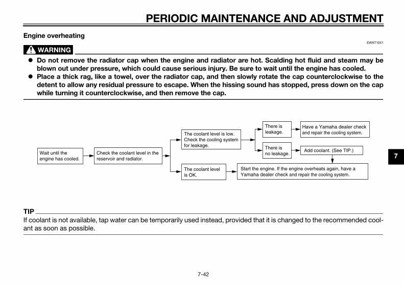
AND ADJUSTMENT
7
EEWAT1041
lding hot fluid and steam may be
until the engine has cooled.
the cap counterclockwise to the
stopped, press down on the cap
T
If changed to the recommended cool-a
Have a Yamaha dealer checkand repair the cooling system.
Add coolant. (See TIP.)
If the engine overheats again, have a heck and repair the cooling system.
isge.
is kage.
U2MS70E0.book Page 42 Thursday, December 18, 2014 1:46 PM
PERIODIC MAINTENANCE
7-42
ngine overheating
WARNING
Do not remove the radiator cap when the engine and radiator are hot. Sca
blown out under pressure, which could cause serious injury. Be sure to wait
Place a thick rag, like a towel, over the radiator cap, and then slowly rotate
detent to allow any residual pressure to escape. When the hissing sound has
while turning it counterclockwise, and then remove the cap.
IP
coolant is not available, tap water can be temporarily used instead, provided that it is nt as soon as possible.
Wait until the engine has cooled.
Check the coolant level in the reservoir and radiator.
The coolant level is OK.
The coolant level is low.Check the cooling systemfor leakage.
Start the engine. Yamaha dealer c
Thereleaka
Thereno lea

M
8
M
N
So
m
su
ad
fo
br
cl
th
th
be
ish
ucts onto seals, gaskets, sprock-ets, the drive chain and wheelaxles. Always rinse the dirt anddegreaser off with water.
aning
TICEECA10773
Avoid using strong acidic wheel
cleaners, especially on spoked
wheels. If such products are
used on hard-to-remove dirt, do
not leave the cleaner on the af-
fected area any longer than in-
structed. Also, thoroughly rinse
the area off with water, immedi-
ately dry it, and then apply a cor-
rosion protection spray.
Improper cleaning can damage
plastic parts (such as cowlings,
panels, windshields, headlight
lenses, meter lenses, etc.) and
the mufflers. Use only a soft,
clean cloth or sponge with wa-
ter to clean plastic. However, if
the plastic parts cannot be thor-
oughly cleaned with water, di-
luted mild detergent with water
may be used. Be sure to rinse
U2MS70E0.book Page 1 Thursday, December 18, 2014 1:46 PM
OTORCYCLE CARE AND STORAGE
8-1
EAU37834
atte color caution
OTICEECA15193
me models are equipped with
atte colored finished parts. Be
re to consult a Yamaha dealer for
vice on what products to use be-
re cleaning the vehicle. Using a
ush, harsh chemical products or
eaning compounds when cleaning
ese parts will scratch or damage
eir surface. Wax also should not
applied to any matte colored fin-
ed parts.
EAU54661
CareWhile the open design of a motorcyclereveals the attractiveness of the tech-nology, it also makes it more vulnera-ble. Rust and corrosion can developeven if high-quality components areused. A rusty exhaust pipe may go un-noticed on a car, however, it detractsfrom the overall appearance of a mo-torcycle. Frequent and proper caredoes not only comply with the terms ofthe warranty, but it will also keep yourmotorcycle looking good, extend itslife and optimize its performance.
Before cleaning
1. Cover the muffler outlet with aplastic bag after the engine hascooled down.
2. Make sure that all caps and cov-ers as well as all electrical cou-plers and connectors, includingthe spark plug caps, are tightly in-stalled.
3. Remove extremely stubborn dirt,like oil burnt onto the crankcase,with a degreasing agent and abrush, but never apply such prod-
Cle
NO

ARE AND STORAGE
8
lt sprayed on roads in the wintery remain well into spring.
. Clean the motorcycle with coldwater and a mild detergent, afterthe engine has cooled down.NOTICE: Do not use warm wa-
ter since it increases the corro-
sive action of the salt. [ECA10792]
. Apply a corrosion protection sprayon all metal, including chrome-and nickel-plated, surfaces to pre-vent corrosion.
aning the windshieldoid using any alkaline or strong acidaner, gasoline, brake fluid, or anyer solvent. Clean the windshieldh a cloth or sponge dampened withild detergent, and then wash it off
roughly with water. For additionalaning, use Yamaha Windshieldaner or another high-quality wind-
ield cleaner. Some cleaning com-unds for plastics may leaveatches on the windshield. Before
ing such cleaners, test an area of the
U2MS70E0.book Page 2 Thursday, December 18, 2014 1:46 PM
MOTORCYCLE C
8-2
off any detergent residue using
plenty of water, as it is harmful
to plastic parts.
Do not use any harsh chemical
products on plastic parts. Be
sure to avoid using cloths or
sponges which have been in
contact with strong or abrasive
cleaning products, solvent or
thinner, fuel (gasoline), rust re-
movers or inhibitors, brake fluid,
antifreeze or electrolyte.
Do not use high-pressure wash-
ers or steam-jet cleaners since
they cause water seepage and
deterioration in the following ar-
eas: seals (of wheel and swing-
arm bearings, fork and brakes),
electric components (couplers,
connectors, instruments,
switches and lights), breather
hoses and vents.
For motorcycles equipped with
a windshield: Do not use strong
cleaners or hard sponges as
they will cause dulling or
scratching. Some cleaning
compounds for plastic may
leave scratches on the wind-
shield. Test the product on a
small hidden part of the wind-
shield to make sure that it does
not leave any marks. If the wind-
shield is scratched, use a quality
plastic polishing compound af-
ter washing.
After normal useRemove dirt with warm water, a milddetergent, and a soft, clean sponge,and then rinse thoroughly with cleanwater. Use a toothbrush or bottlebrushfor hard-to-reach areas. Stubborn dirtand insects will come off more easily ifthe area is covered with a wet cloth fora few minutes before cleaning.
After riding in the rain, near the sea oron salt-sprayed roadsSince sea salt or salt sprayed on roadsduring winter are extremely corrosivein combination with water, carry outthe following steps after each ride inthe rain, near the sea or on salt-sprayed roads.
TIP
Sama
1
2
CleAvcleothwita mthocleCleshposcrus

M
8
wivisre
Af
1
2
3
4
5
6
78
Consult a Yamaha dealer for ad-vice on what products to use.Washing, rainy weather or humidclimates can cause the headlightlens to fog. Turning the headlighton for a short period of time willhelp remove the moisture from thelens.
U2MS70E0.book Page 3 Thursday, December 18, 2014 1:46 PM
OTORCYCLE CARE AND STORAGE
8-3
ndshield which does not affect youribility and which cannot be easily
cognized.
ter cleaning
. Dry the motorcycle with a chamoisor an absorbing cloth.
. Immediately dry the drive chainand lubricate it to prevent it fromrusting.
. Use a chrome polish to shinechrome, aluminum and stainless-steel parts, including the exhaustsystem. (Even the thermally in-duced discoloring of stainless-steel exhaust systems can be re-moved through polishing.)
. To prevent corrosion, it is recom-mended to apply a corrosion pro-tection spray on all metal,including chrome- and nickel-plat-ed, surfaces.
. Use spray oil as a universal clean-er to remove any remaining dirt.
. Touch up minor paint damagecaused by stones, etc.
. Wax all painted surfaces.
. Let the motorcycle dry completelybefore storing or covering it.
WARNING
EWA11132
Contaminants on the brakes or tires
can cause loss of control.
Make sure that there is no oil or
wax on the brakes or tires.
If necessary, clean the brake
discs and brake linings with a
regular brake disc cleaner or
acetone, and wash the tires with
warm water and a mild deter-
gent. Before riding at higher
speeds, test the motorcycle’s
braking performance and cor-
nering behavior.
NOTICEECA10801
Apply spray oil and wax spar-
ingly and make sure to wipe off
any excess.
Never apply oil or wax to any
rubber and plastic parts, but
treat them with a suitable care
product.
Avoid using abrasive polishing
compounds as they will wear
away the paint.
TIP

ARE AND STORAGE
8
S
S
Adasuteto
N
L
Be
e. Remove the spark plug capsfrom the spark plugs, and theninstall the spark plugs and thespark plug caps.
. Lubricate all control cables andthe pivoting points of all levers andpedals as well as of the side-stand/centerstand.
. Check and, if necessary, correctthe tire air pressure, and then liftthe motorcycle so that both of itswheels are off the ground. Alterna-tively, turn the wheels a little everymonth in order to prevent the tiresfrom becoming degraded in onespot.
. Cover the muffler outlet with aplastic bag to prevent moisturefrom entering it.
. Remove the battery and fullycharge it. Store it in a cool, dryplace and charge it once a month.Do not store the battery in an ex-cessively cold or warm place [lessthan 0 °C (30 °F) or more than 30°C (90 °F)]. For more informationon storing the battery, see page7-29.
U2MS70E0.book Page 4 Thursday, December 18, 2014 1:46 PM
MOTORCYCLE C
8-4
EAU26183
torage
hort-term
lways store your motorcycle in a cool,ry place and, if necessary, protect itgainst dust with a porous cover. Bere the engine and the exhaust sys-m are cool before covering the mo-rcycle.
OTICEECA10811
Storing the motorcycle in a
poorly ventilated room or cover-
ing it with a tarp, while it is still
wet, will allow water and humid-
ity to seep in and cause rust.
To prevent corrosion, avoid
damp cellars, stables (because
of the presence of ammonia)
and areas where strong chemi-
cals are stored.
ong-term
efore storing your motorcycle for sev-ral months:1. Follow all the instructions in the
“Care” section of this chapter.
2. Fill up the fuel tank and add fuelstabilizer (if available) to preventthe fuel tank from rusting and thefuel from deteriorating.
3. Perform the following steps toprotect the cylinders, piston rings,etc. from corrosion.a. Remove the spark plug caps
and spark plugs.b. Pour a teaspoonful of engine
oil into each spark plug bore.c. Install the spark plug caps onto
the spark plugs, and thenplace the spark plugs on thecylinder head so that the elec-trodes are grounded. (This willlimit sparking during the nextstep.)
d. Turn the engine over severaltimes with the starter. (This willcoat the cylinder walls with oil.)WARNING! To prevent dam-
age or injury from sparking,
make sure to ground the
spark plug electrodes while
turning the engine over.
[EWA10952]
4
5
6
7
M
8
TI
Mst
U2MS70E0.book Page 5 Thursday, December 18, 2014 1:46 PM
OTORCYCLE CARE AND STORAGE
8-5
P
ake any necessary repairs beforeoring the motorcycle.

SPECIFICATIONS
9
D
W
E
el:ecommended fuel:
Regular unleaded gasoline (Gasohol (E10) acceptable)
uel tank capacity:14 L (3.7 US gal, 3.08 Imp.gal)
uel reserve amount:3.0 L (0.79 US gal, 0.66 Imp.gal)
el injection:hrottle body:
ID mark:2MS2 00
ark plug(s):anufacturer/model:NGK/CR8E
park plug gap:0.7–0.8 mm (0.028–0.031 in)
tch:lutch type:Wet, multiple-disc
nsmission:rimary reduction ratio:
3.043 (70/23)inal drive:
Chainecondary reduction ratio:
3.071 (43/14)ransmission type:
Constant mesh 6-speedperation:Left foot operation
ear ratio:1st:
2.500 (35/14)
U2MS70E0.book Page 1 Thursday, December 18, 2014 1:46 PM
9-1
imensions:Overall length:
2090 mm (82.3 in)Overall width:
720 mm (28.3 in)Overall height:
1135 mm (44.7 in)Seat height:
780 mm (30.7 in)Wheelbase:
1380 mm (54.3 in)Ground clearance:
160 mm (6.30 in)Minimum turning radius:
2700 mm (106.3 in)eight:Curb weight:
166 kg (366 lb)ngine:Engine type:
Liquid cooled 4-stroke, DOHCCylinder arrangement:
Inline 2-cylinderDisplacement:
321 cm3Bore × stroke:
68.0 × 44.1 mm (2.68 × 1.74 in)Compression ratio:
11.2 : 1Starting system:
Electric starterLubrication system:
Wet sump
Engine oil:Recommended brand:
YAMALUBEType:
SAE 10W-30, 10W-40, 10W-50, 15W-40, 20W-40 or 20W-50
Recommended engine oil grade:API service SG type or higher, JASO standard MA
Engine oil quantity:Without oil filter cartridge replacement:
1.80 L (1.90 US qt, 1.58 Imp.qt)With oil filter cartridge replacement:
2.10 L (2.22 US qt, 1.85 Imp.qt)Coolant quantity:
Coolant reservoir (up to the maximum level mark):
0.25 L (0.26 US qt, 0.22 Imp.qt)Radiator (including all routes):
0.96 L (1.01 US qt, 0.84 Imp.qt)Air filter:
Air filter element:Oil-coated paper element
FuR
F
F
FuT
SpM
S
CluC
TraP
F
S
T
O
G
–20 –10 0 10 20 30 40 50 ˚C
10 30 50 70 90 1100 130 ˚F
SAE 10W-30
SAE 15W-40
SAE 20W-40
SAE 20W-50
SAE 10W-40
SAE 10W-50

S
9
Ch
Fr
Re
Lo
r brake:ype:
Single disc brakeperation:Right foot operation
pecified brake fluid:DOT 4
nt suspension:ype:
Telescopic forkpring/shock absorber type:
Coil spring/oil damperheel travel:130 mm (5.1 in)
r suspension:ype:
Swingarmpring/shock absorber type:
Coil spring/oil damperheel travel:125 mm (4.9 in)
ctrical system:nition system:TCI
harging system:AC magneto
tery:odel:GTZ8V
oltage, capacity:12 V, 7.0 Ah
dlight:ulb type:
Halogen bulb
U2MS70E0.book Page 2 Thursday, December 18, 2014 1:46 PM
PECIFICATIONS
9-2
2nd:1.824 (31/17)
3rd:1.348 (31/23)
4th:1.087 (25/23)
5th:0.920 (23/25)
6th:0.800 (24/30)
assis:Frame type:
DiamondCaster angle:
25.00 °Trail:
95 mm (3.7 in)ont tire:Type:
TubelessSize:
110/70-17M/C (54H)Manufacturer/model:
MICHELIN/PILOT STREETar tire:Type:
TubelessSize:
140/70-17M/C (66H)Manufacturer/model:
MICHELIN/PILOT STREETading:Maximum load:
160 kg (353 lb)
(Total weight of rider, passenger, cargo and accessories)
Tire air pressure (measured on cold
tires):Loading condition:
0–90 kg (0–198 lb)Front:
200 kPa (2.00 kgf/cm2, 29 psi)Rear:
250 kPa (2.50 kgf/cm2, 36 psi)Loading condition:
90–160 kg (198–353 lb)Front:
200 kPa (2.00 kgf/cm2, 29 psi)Rear:
250 kPa (2.50 kgf/cm2, 36 psi)Front wheel:
Wheel type:Cast wheel
Rim size:17M/C x MT2.75
Rear wheel:Wheel type:
Cast wheelRim size:
17M/C x MT4.00Front brake:
Type:Single disc brake
Operation:Right hand operation
Specified brake fluid:DOT 4
ReaT
O
S
FroT
S
W
ReaT
S
W
EleIg
C
BatM
V
HeaB

SPECIFICATIONS
9
B
F
U2MS70E0.book Page 3 Thursday, December 18, 2014 1:46 PM
9-3
ulb voltage, wattage × quantity:Headlight:
12 V, 55.0 W × 2Tail/brake light:
LEDFront turn signal/position light:
12 V, 21.0 W/5.0 W × 2Rear turn signal light:
12 V, 21.0 W × 2Auxiliary light:
12 V, 5.0 W × 1License plate light:
12 V, 5.0 W × 1Meter lighting:
LEDNeutral indicator light:
LEDHigh beam indicator light:
LEDOil pressure warning light:
LEDTurn signal indicator light:
LEDEngine trouble warning light:
LEDuses:
Main fuse:30.0 A
Headlight fuse:15.0 A
Signaling system fuse:15.0 A
Ignition fuse:15.0 A
Radiator fan motor fuse:7.5 A
Backup fuse:7.5 A

C
10
IdRebeinfnuThedthorde
VE
EN
M
EAU26442
ine serial number
engine serial number is stamped the crankcase.
EAU26521
del label
ngine serial number
odel label
1
1
U2MS70E0.book Page 1 Thursday, December 18, 2014 1:46 PM
ONSUMER INFORMATION
10-1
EAU26357
entification numberscord the vehicle identification num-r, engine serial number, model labelormation, and the key identificationmber in the spaces provided below.ese identification numbers are need- when registering the vehicle withe authorities in your area and whendering spare parts from a Yamahaaler.
HICLE IDENTIFICATION NUMBER:
GINE SERIAL NUMBER:
ODEL LABEL INFORMATION:
KEY IDENTIFICATION NUMBER:
EAU62971
Vehicle identification number
The vehicle identification number isstamped into the frame under the pas-senger seat. (See page 4-16.)
TIP
The vehicle identification number isused to identify your vehicle and maybe used to register it with the licensingauthority in your area.
Eng
Theinto
Mo
1. Vehicle identification number
1
1. E
1. M

MER INFORMATION
10
Tu4lamsp
K
Tstnitk
1.
U2MS70E0.book Page 2 Thursday, December 18, 2014 1:46 PM
CONSU
10-2
he model label is affixed to the framender the passenger seat. (See page-16.) Record the information on thisbel in the space provided. This infor-ation will be needed when orderingare parts from a Yamaha dealer.
EAU26382
ey identification number
he key identification number isamped into the key tag. Record thisumber in the space provided and use for reference when ordering a newey.
EAU48271
Vehicle Emission Control Informa-
tion label
The Vehicle Emission Control Informa-tion label is affixed at the location in theillustration. This label shows specifica-tions related to exhaust emissions asrequired by federal law, state law andEnvironment Canada.
Key identification number
1
1. Vehicle Emission Control Information label
1

C
10
EAU26622
MCo rcycle will be required to documentth chart below is printed only as a re-m ork.
leress
Remarks
U2MS70E0.book Page 3 Thursday, December 18, 2014 1:46 PM
ONSUMER INFORMATION
10-3
aintenance recordpies of work orders and/or receipts for parts purchased and installed on your moto
at maintenance has been completed in accordance with the emissions warranty. Theinder that maintenance work is required. It is not acceptable proof of maintenance w
Maintenanceinterval
Date of service
MileageServicing dea
name and addr
1000 km(600 mi) or1 month6000 km
(4000 mi) or6 months11000 km
(7000 mi) or12 months16000 km
(10000 mi) or18 months21000 km
(13000 mi) or24 months26000 km
(16000 mi) or30 months31000 km
(19000 mi) or36 months36000 km
(22000 mi) or42 months41000 km
(25000 mi) or48 months
MER INFORMATION
10
lerress
Remarks
U2MS70E0.book Page 4 Thursday, December 18, 2014 1:46 PM
CONSU
10-4
46000 km(28000 mi) or54 months51000 km
(31000 mi) or60 months
Maintenanceinterval
Date of service
MileageServicing dea
name and add

C
10
EAU26718
YA E
CYobrThanIf qureKeprcoFoYa48(4
Inm(‘MbyanshreteM
1.
is warranty does not apply unless:
Y
Sco
S
The MOTORCYCLE has been fully assembled and set to the MANUFACTURER’s operating specifications by a DEALER prior to DELIVERY to the CUSTOMER.The CUSTOMER has followed the break-in and storage instructions contained in the Owner’s Manual and all other instructions shown in the Owner’s Manual.The CUSTOMER can provide record of maintenance having been performed as recommended in the Owner’s Manual.Requests for repairs under warranty have been made as prescribed in Section C.is warranty does not cover the repair of damage resulting m abuse or neglect of the MOTORCYCLE. Examples of use and neglect include, but are not limited to:racing, competition, MOTORCYCLE models designated WR or YZ, with the exception of WR25R, WR25X and YZ85 models, modification of original parts or abnormal strain;use of lubricants, oils, fuel, fuel additives and mixtures other than those recommended in the Owner’s Manual, improperly installed accessories or use of parts or accessories that are not equivalent in design and quality to genuine Yamaha parts;
ion D — Exclusions
damage as a result of accidents, collisions, contact with foreign materials, impact, submersion or use of the MOTORCYCLE after discovery of a defect;appearance-related damages of body parts. Examples of such damages include but are not limited to: scratches, dents, fading, flaking, peeling.is warranty does not extend to:MOTORCYCLES which have been modified in any way from the standard specifications as shown in the Owner’s Manual, including any MOTORCYCLE whose odometer has been altered;normal wear and tear, corrosion and routine maintenance, such as the recommended service inspections;pre-delivery inspection and assembly;MOTORCYCLES from which the MANUFACTURER’s identification numbers have been removed or whose identification numbers have been altered or mutilated;wear and tear and/or maintenance parts such as drive chains, clutch plates and facings, oils and lubricants, spark plugs, batteries, generator brushes, sealed beams and light bulbs, tires, filters, brake pads, drive belts and fuses;inconvenience, loss of time, loss of income or loss of use of the MOTORCYCLE or any consequential damage of any kind;
U2MS70E0.book Page 5 Thursday, December 18, 2014 1:46 PM
ONSUMER INFORMATION
10-5
MAHA MOTOR CANADA LTD. MOTORCYCLE WARRANTY GUID
ongratulations on the purchase of your new Yamaha motorcycle. u have chosen a quality product designed and manufactured to ing you years of enjoyment.is information explains Yamaha’s warranty policy. You will find the swers to most of your questions by reading it through.you require further assistance, see your Yamaha dealer. Their alified personnel will be pleased to meet all your service quirements, both during and after the warranty period.ep in mind that Yamaha manufactures many other quality
oducts too. For further information on our complete line-up, ntact your dealer or visit our web site.r a product brochure, or a dealer near you, go to our web site.maha Motor Canada Ltd. 0 Gordon Baker Road, Toronto, Ontario M2H 3B416) 498-1911 www.yamaha-motor.ca
this warranty, the term ‘MOTORCYCLE’ shall refer to a new otorcycle manufactured by YAMAHA MOTOR COMPANY, LTD. ANUFACTURER’) under the trade name of Yamaha, distributed
YAMAHA MOTOR CANADA LTD. (‘YAMAHA’), sold at retail by authorized Yamaha dealer (‘DEALER’). The term ‘CUSTOMER’ all refer to the owner or lessee of record of the MOTORCYCLE gistered with YAMAHA and to any subsequent owner, and the rm ‘DELIVERY’ shall refer to the date of delivery of the OTORCYCLE from the DEALER to the CUSTOMER.
Periods of warranty:
Th1.
Pleasure Use (including government use)a)
Any part defective by reason of the MANUFACTURER’s faulty workmanship or material will be replaced or repaired free of charge.
a)
the complete model and serial number as shown on the original warranty document;
1.
the name of the previous owner;2.the original delivery date of the MOTORCYCLE;3.the complete name and address of the subsequent owner;4.the indication that the subsequent owner has received and read the Owner’s Manual and this warranty policy.
5.
Any repairs or adjustments made necessary by reason of the MANUFACTURER’s faulty workmanship or material will be performed free of charge.
b)
The period of warranty shall be ninety days commencing on DELIVERY on all models designated PW, TT and on YZ85 models.The period of warranty shall be one year commencing on DELIVERY on all other models.
i) Basic Period of Warranty
In the event DELIVERY occurs between January 1st and April 30th, the warranty shall extend to April 30th of the following year.
ii) Additional Period of Warranty for Street-Legal Motorcycles
amaha Motorcycle Warranty Policy
ubject to Section D, YAMAHA offers the following warranty verage to the CUSTOMER:
ection A — Warranty
During these periods of warranty:2.
The MANUFACTURER reserves the right to change the design of any model without obligation to modify any model previously manufactured.
The warranty set forth in Section A may be transferred to any subsequent owner provided that the period of warranty has not expired and that the CUSTOMER has complied with all terms and conditions of this warranty.The subsequent owner has the responsibility for ensuring that a change of registration is sent to YAMAHA at the time of such transfer of ownership.This transfer MUST be done by contacting the DEALER who will forward the following information to YAMAHA:
Section B — Subsequent Owner
a)
b)
c)
d)
Thfroab
2.
a)
b)
Sect
Ensure that the MOTORCYCLE is properly operated, maintained and stored as specified in the Owner’s Manual.
1.
Give notice to a DEALER of any and all apparent defects immediately upon discovery, and make the entire MOTORCYCLE available at that time for inspection and repair at the DEALER’S place of business.
2.
Provide proof of warranty coverage to such DEALER (CUSTOMER’S copy of the New Vehicle Information Statement: N.V.I.S.).
3.
Authorize the DEALER to tear down the MOTORCYCLE for diagnostic evaluation should it be required.
4.
To obtain repairs under warranty, the CUSTOMER must:Section C — Obtaining Repairs Under Warranty
All warranty repairs must be done by a DEALER and final approval of any repairs rests with YAMAHA. All parts replaced become the property of YAMAHA.
Commercial Useb)The period of warranty shall be half of the warranty period indicated for pleasure use, commencing on DELIVERY on any MOTORCYCLE which has been identified as being used for commercial applications.
c)
d)
Th3.a)
b)
c)d)
e)
f)
MER INFORMATION
10
E512
Yctcsfnboaw
S(
TwSwifowYonopYat
S
Twrw
O
U2MS70E0.book Page 6 Thursday, December 18, 2014 1:46 PM
CONSU
10-6
Periodngine Displacement12,000 km or 5 years, whichever occurs first0cc to 169cc18,000 km or 5 years, whichever occurs first70cc to 279cc30,000 km or 5 years, whichever occurs first80cc and over
Brakes•Clutch•Fluid Levels•Drive System•Cooling System•Fuel / Throttle System•Wheels / Tires / Suspension•Steering and Controls•Electrical System•Replacing damaged or missing parts•Test Ride•
damages from theft, fire, vandalism, explosion, water or acts of God;
g)
storage costs, or transportation and shipping costs related to the performance of this warranty;
h)
damage due to “flat towing” (see your DEALER for explanation).
i)
AMAHA warrants to the CUSTOMER of a MOTORCYCLE overed by this warranty with a displacement of 50cc or greater, hat the MOTORCYCLE is designed, built and equipped so as to onform at the time of DELIVERY with all federal emissions tandards applicable at the time of manufacture and that it is free rom defects in materials and workmanship which would cause it ot to meet these standards within the periods listed immediately elow. Failures other than those resulting from defects in material r workmanship, which arise solely as a result of owner abuse nd/or lack of proper maintenance, are not covered by this arranty.
ection E — Emissions Control System Warranty For applicable models only)
his warranty is in addition to, and not a modification of, any arranty required by the laws of any province of Canada.ubject to any applicable sales or consumer legislation, the above arranty is in lieu of any warranty or representation, expressed or
mplied, including any warranty of performance, merchantability or itness for a particular purpose on the part of YAMAHA, and any ther obligation or liability on behalf of YAMAHA, and the above arranty constitutes your sole remedy and the full liability of AMAHA. In no event shall YAMAHA be liable for special, incidental r consequential damages howsoever caused, whether by egligence or otherwise resulting directly or indirectly from the use f the MOTORCYCLE, or the MOTORCYCLE having replacement arts or the unavailability of replacement parts.AMAHA does not assume, or authorize any person to create or ssume for YAMAHA, any obligation or liability in connection with he MOTORCYCLE or any part thereof distributed by YAMAHA.
ection F
ires supplied as original equipment on your MOTORCYCLE are arranted separately by the individual tire manufacturer or its
epresentatives. Generally speaking, this warranty covers defects in orkmanship or material.
riginal Equipment Tires
If your MOTORCYCLE is not to be used for 60 days or more, it must be properly stored to ensure against deterioration. You should consult your Owner’s Manual for storage details, but WE RECOMMEND THAT YOU HAVE AN AUTHORIZED YAMAHA MOTORCYCLE DEALER PREPARE YOUR MOTORCYCLE FOR STORAGE. Their highly-trained staff have the experience and the qualifications to do the job right.YAMAHA cannot accept responsibility for damage to your vehicle or personal injury resulting from negligence or lack of experience in the preparation of your MOTORCYCLE for storage.
Storing Your MOTORCYCLE
The DEALER has assembled, inspected and tested the MOTORCYCLE according to the Yamaha Motorcycle Pre-delivery Inspection Checklist prior to DELIVERY to the CUSTOMER (some items may not be applicable to all models). These items include:
The Yamaha Motorcycle Pre-delivery Inspection Checklist has been provided to the CUSTOMER at the time of DELIVERY.
Pre-delivery Inspection Checklist
If you should move after you have purchased your MOTORCYCLE, please contact the DEALER who will forward the required information to YAMAHA. Provide the DEALER with the model name and serial number as shown on the N.V.I.S., along with your new mailing address (or other information). This will ensure that YAMAHA has an up-to-date registration record.
Change of Address or Other Owner Information

1
utral indicator light..............................4-2
l pressure warning light .......................4-2
rking ....................................................6-4rt locations ..........................................3-1ss switch...........................................4-11
ar view mirrors ..................................4-18
fety information...................................2-1ats .....................................................4-16ifting ....................................................6-2ift pedal.............................................4-12ift timing indicator light .......................4-3ock absorber assembly, adjusting....4-18estand ..............................................4-19estand, checking and lubricating.....7-27ark plugs, checking ............................7-9ecifications .........................................9-1arting the engine..................................6-1art switch ...........................................4-11eering, checking ................................7-29orage ...................................................8-4orage compartment ...........................4-18pporting the motorcycle ...................7-36ingarm pivots, lubricating ................7-28
il/brake light ......................................7-34rottle grip and cable, hecking and lubricating ....................7-26rottle grip free play, checking ...........7-16es ......................................................7-16
U2MS70E0.book Page 1 Thursday, December 18, 2014 1:46 PM
1
IN
AAi
rAu
BBB
cB
cBBBBBB
CCCCCCC
DDDD
EEnEnEnEnEn
11-1
DEX
r filter element and check hose, eplacing and cleaning .......................7-14xiliary light bulb.................................7-33
attery ..................................................7-29rake and clutch levers, hecking and lubricating ....................7-27
rake and shift pedals, hecking and lubricating ....................7-26
rake fluid, changing ............................7-23rake fluid level, checking ....................7-21rake lever ............................................4-12rake lever free play, checking.............7-20rake light switches..............................7-20rake pedal...........................................4-12
ables, checking and lubricating .........7-25are ........................................................8-1atalytic converter................................4-15lutch lever...........................................4-11lutch lever free play, adjusting ...........7-18oolant .................................................7-13
immer switch ......................................4-11rive chain, cleaning and lubricating....7-25rive chain slack...................................7-23
gine break-in.......................................6-4gine oil and oil filter cartridge ...........7-10gine serial number ............................10-1gine stop switch ...............................4-11gine trouble warning light ...................4-3
FFront and rear brake pads, checking ... 7-21Front fork, checking ............................. 7-28Fuel....................................................... 4-13Fuel tank breather hose and
overflow hose..................................... 4-15Fuel tank cap........................................ 4-13Fuses, replacing ................................... 7-31
HHandlebar switches.............................. 4-10Headlight bulb, replacing ..................... 7-32Helmet holders ..................................... 4-17High beam indicator light ....................... 4-2Horn switch .......................................... 4-11
IIdentification numbers.......................... 10-1Ignition circuit cut-off system............... 4-20Indicator lights and warning lights ......... 4-2
KKey identification number..................... 10-2
LLabels, location ...................................... 1-1License plate light bulb, replacing........ 7-35Luggage strap holders ......................... 4-19
MMain switch/steering lock....................... 4-1Maintenance and lubrication, periodic ... 7-5Maintenance, emission control
system.................................................. 7-4Maintenance record ............................. 10-3Matte color, caution ............................... 8-1Model label........................................... 10-1Multi-function meter unit ........................ 4-4
NNe
OOi
PPaPaPa
RRe
SSaSeShShShShSidSidSpSpStStStStStSuSw
TTaTh
cThTir
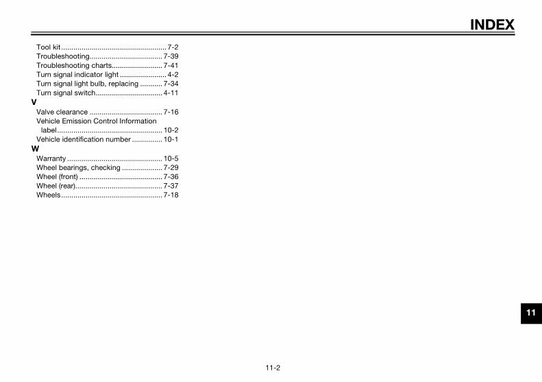
INDEX
11
V
W
U2MS70E0.book Page 2 Thursday, December 18, 2014 1:46 PM
11-2
Tool kit .................................................... 7-2Troubleshooting.................................... 7-39Troubleshooting charts......................... 7-41Turn signal indicator light ....................... 4-2Turn signal light bulb, replacing ........... 7-34Turn signal switch................................. 4-11
Valve clearance .................................... 7-16Vehicle Emission Control Information
label.................................................... 10-2Vehicle identification number ............... 10-1
Warranty ............................................... 10-5Wheel bearings, checking .................... 7-29Wheel (front) ......................................... 7-36Wheel (rear)........................................... 7-37Wheels.................................................. 7-18

U2MS70E0.book Page 3 Thursday, December 18, 2014 1:46 PM

EAU55803
ts as the ones originally come to expect. Why settle for
tandards for quality and right and perform right – right
are products. They’re formulated ow your Yamaha from the inside
at the technicians at your aler or you can order them
U2MS70E0.book Page 1 Thursday, December 18, 2014 1:46 PM
Fo
Geeqaft
Gepeou
Yaanou
Geaudir
Ge
FinFoFo
r your best ownership experience, think Genuine Yamaha!
nuine Yamaha Parts – Genuine Yamaha replacement parts are the exact same paruipped on your vehicle, providing you with the performance and durability you have ermarket parts that may not provide full confidence and satisfaction?
nuine Yamaha Accessories – Yamaha only offers accessories that meet our high srformance. Buy with confidence, knowing your Genuine Yamaha Accessories will fit t of the box.
malube – Take care of your Yamaha with legendary Yamalube oils, lubricants, and cd approved by the toughest judges we know: the Yamaha engineering teams that knt.
nuine Yamaha Service Manuals – Get the same factory manual for your vehicle ththorized Yamaha dealer use. Service manuals are available through your Yamaha deectly through yamahapubs.com (for US consumers only).
nuine Yamaha products are available only from your Yamaha dealer.
d out more at:r US consumers, please visit yamaha-motor.comr Canadian consumers, please visit yamaha-motor.ca

DIC183