2018 short-circuit and earth fault indicators solutions ... · the opto f+e 3.0 device is a...
TRANSCRIPT

2018
Short-Circuit and Earth Fault IndicatorsSolutions for Remote MonitoringVoltage Detectors and Detecting SystemsEarthing Devices and Accessories
2018
2
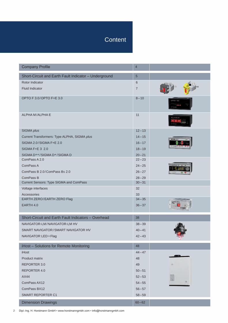
Company Profile 4
Short-Circuit and Earth Fault Indicators – Overhead 38
NAVIGATOR-LM / NAVIGATOR-LM HV
SMART NAVIGATOR / SMART NAVIGATOR HV
NAVIGATOR LED + Flag
38 – 39
40 – 41
42 – 43
Dimension Drawings 60 – 62
Short-Circuit and Earth Fault Indicator – Underground 5
Rotor Indicator
Fluid Indicator
6
7
OPTO F 3.0 / OPTO F+E 3.0 8 – 10
ALPHA M / ALPHA E 11
SIGMA plus
Current Transformers: Type ALPHA, SIGMA plus
SIGMA 2.0 / SIGMA F+E 2.0
SIGMA F+E 3 2.0
SIGMA D++ / SIGMA D+ / SIGMA D
12 – 13
14 – 15
16 – 17
18 – 19
20 – 21ComPass A 2.0
ComPass A
ComPass B 2.0 / ComPass BS 2.0
ComPass B
22 – 23
24 – 25
26 – 27
28 – 29Current Sensors: Type SIGMA and ComPass 30 – 31
Voltage interfaces
Accessories
32
33EARTH ZERO / EARTH ZERO Flag
EARTH 4.0
34 – 35
36 – 37
iHost – Solutions for Remote Monitoring 48
iHost
Product matrix
REPORTER 3.0
REPORTER 4.0
AX44
ComPass AX12
ComPass BX12
SMART REPORTER C1
44 – 47
48
49
50 – 51
52 – 53
54 – 55
56 – 57
58 – 59
Dipl.-Ing. H. Horstmann GmbH www.horstmanngmbh.com [email protected]
Content

3
63 Voltage Detectors and Voltage Detecting Systems64 – 65
66
67
68 – 69
70 – 71
72 – 73
74 – 75
76 – 77
78 – 79
80 – 81
82
Product matrix
FL-I
TP-I
Comet BL-I / Comet BL-A
Comet BK-I / Comet BK-A
Comet 2.0 BS-I / Comet 2.0 BS-A
BO-A 2.0
COMPARE 2.0
PG II
BL-M
Accessories: For voltage detectors, phase comparators and voltmeter83
84
85
86
87
WEGA 1.2 C
WEGA 1.2 C vario
WEGA 2.2 C
WEGA 3
WEGA T188 – 89
90
91
92
ORION 3.1 / ORION M1
HR-ST / LRM-ST
Interface Adapter Converter
Maintenance Test
93 – 94 Dimension Drawings
95 Earthing Devices and Accessories96 – 97
98
Earthing and Short-Circuiting Devices
Single-Pole Earthing and Short-Circuiting Cables
99
100 – 101
102 – 105
Short-Circuit Bars
Phase Connecting Points and Phase Connecting Elements
Earth Connecting Points and Earth Connecting Elements
106 – 107
108 – 109
110
111
Hot Sticks
Operating Rods
Earthing Sticks
Fuse Tongs112
113
114
Wall Holders
Accessories
Insulating Protective Barrier
115 Fuse Testing Devices
119 – 121 Project Planning / Order / Inquiry
Dipl.-Ing. H. Horstmann GmbH www.horstmanngmbh.com [email protected]
Content

4
Head office in Heiligenhaus
In-house manufacturing
Component testing
High voltage laboratory
Dipl.-Ing. H. Horstmann GmbH www.horstmanngmbh.com [email protected]
Company Profile
Dipl.-Ing. H. Horstmann GmbH is a medium-sized company based in Heili-genhaus near Düsseldorf (Germany). The company was founded in 1946 by Heinrich Horstmann. Since that time it has been a successful family- owned company. Due to its long experience and the ongoing expansion activities in research and development as well as in production facilities Dipl.-Ing. H. Horstmann GmbH is today recognized as the leading manufacturer in medium voltage technology for:
Short-circuit and earth fault indicators Solutions for Remote Monitoring Voltage detectors and voltage detecting systems Earthing devices and accessories.
The worldwide distribution is covered by both our own highly qualified sales force and trade agents.
Our products meet the highest quality requirements and are developed and manufactured in own production facilities in Germany. In order to respond to these demands, we have a very high vertical depth of production (e. g. own SMD assembly lines) as well as an own research and development department with state-of-the-art testing and measuring equipment. Besides the electronics manufacturing, we have also a mechanical production facility for safety material.
Our company has been certified according to DIN EN ISO 9001 since 1996.

5
G
G
Transformer Station
Decentralized feed in
Fault indicator (tripped)
Substation
Fault indicator (not tripped)
Directional fault indicator (tripped)
Protection indication with release
Failure location
Dipl.-Ing. H. Horstmann GmbH www.horstmanngmbh.com [email protected]
Short-Circuit and Earth Fault IndicatorGeneral information
Short-circuit indicators are devices which are tripped by a magnetic field in-duced by the current flow in a conductor when a short-circuit occurs and indi-cate that the device has tripped.
Short-circuit indicators are mainly used for an efficient and quick fault location in medium voltage distribution networks (radially fed, open-ring or closed-ring networks). They are mounted on current-carrying busbars, cables or overhead lines. Any fault condition that exceeds pre-set trip currents of the short-circuit indicator produces a trip signal leading to a visual indication without information on the direction of the fault. This signal can also be remotely indicated.
In case of a short-circuit, if additional decentralized power feeders, e. g. from photovoltaics or wind parks, are connected to the existing energy distribution network, both the substation and the decentralized feeding sources feed in from two directions to the fault. In such cases, short-circuit/earth fault indicators with indication of fault direction are required (see circuit diagram below, right hand-side).
Short-circuit indicators can also be used as earth fault indicators provided that a single-phase current fault of sufficiently high level occurs in the faulty line sec-tion. In cases where low current faults occur, it is recommended to use short-cir-cuit indicators with additional summation current transformers.
The fault is located between the last tripped short-circuit indicator and the first following untripped short-circuit indicator (see circuit diagram below, left hand-side).

Technical data Rotor IndicatorI>> Short-circuit trip current 150 – 2,000 A (factory setting)tI>> Response time 100 ms at rated trip valueAccuracy ±10 %Reset Manual reset with hot stickMaterial Housing and fixing screws made from poly-
amide Yoke made from ferromagnetic steel
Temperature range -40 to +85 °C
I min [A] for Ø [mm] Order no.150 8 – 16 20-0101-0011)
200 16 – 20 20-0102-001200 20 – 30 20-0103-001200 30 – 40 20-0104-001200 40 – 50 20-0105-001300 50 – 60 20-0106-001300 60 – 80 20-0108-001I min [A] for [mm]150 20 x 4 – 25 x 6 20-0122-0011)
150 25 x 4 – 30 x 6 20-0123-0011)
200 30 x 4 – 40 x 10 20-0120-0011)
300 45 x 4 – 60 x 12 20-0121-0011)
AccessoriesHot stick See on page 106
6
Rotor Indicator
Installation
Response characteristic
Short-circuit trip current
Res
pons
e tim
e t [
ms]
Dipl.-Ing. H. Horstmann GmbH www.horstmanngmbh.com [email protected]
Product features Mechanical design Installation on cables or busbars Fault indication by pivoted rotor Retrofit ready
The Rotor Indicator is a mechanical short-circuit indicator. It is designed to de-tect short-circuit currents in medium voltage distribution networks.
The indicator is tripped by a magnetic field strength “H” which is induced by trip values I>>. The pivoted rotor with reset pin uses a two-colour indication to in-form the user of the state of the Rotor Indicator. “Black” means that the indicator has not been tripped whereas “red” indicates that the indicator has been tripped.
Dimension drawing see on page 60, M1
Combined rotor / fluid type short-circuit indicators are available on request.1) Screws for fixing the conductor made of steel
Rotor IndicatorMechanical short-circuit indicator
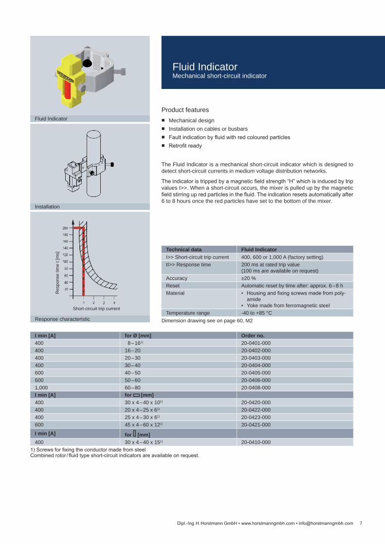
Technical data Fluid IndicatorI>> Short-circuit trip current 400, 600 or 1,000 A (factory setting)tI>> Response time 200 ms at rated trip value
(100 ms are available on request)Accuracy ±20 %Reset Automatic reset by time after: approx. 6 – 8 hMaterial Housing and fixing screws made from poly-
amide Yoke made from ferromagnetic steel
Temperature range -40 to +85 °C
I min [A] for Ø [mm] Order no.400 8 – 161) 20-0401-000400 16 – 20 20-0402-000400 20 – 30 20-0403-000400 30 – 40 20-0404-000600 40 – 50 20-0405-000600 50 – 60 20-0406-0001,000 60 – 80 20-0408-000I min [A] for [mm]400 30 x 4 – 40 x 101) 20-0420-000400 20 x 4 – 25 x 61) 20-0422-000400 25 x 4 – 30 x 61) 20-0423-000600 45 x 4 – 60 x 121) 20-0421-000
I min [A] for [mm]400 30 x 4 – 40 x 151) 20-0410-000
7
Installation
Response characteristic
Short-circuit trip current
Res
pons
e tim
e t [
ms]
Fluid Indicator
Dipl.-Ing. H. Horstmann GmbH www.horstmanngmbh.com [email protected]
Product features Mechanical design Installation on cables or busbars Fault indication by fluid with red coloured particles Retrofit ready
The Fluid Indicator is a mechanical short-circuit indicator which is designed to detect short-circuit currents in medium voltage distribution networks.
The indicator is tripped by a magnetic field strength “H” which is induced by trip values I>>. When a short-circuit occurs, the mixer is pulled up by the magnetic field stirring up red particles in the fluid. The indication resets automatically after 6 to 8 hours once the red particles have set to the bottom of the mixer.
Combined rotor / fluid type short-circuit indicators are available on request.
Dimension drawing see on page 60, M2
1) Screws for fixing the conductor made from steel
Fluid IndicatorMechanical short-circuit indicator

8
OPTO-F 3.0, plug-in housing
OPTO-F 3.0, surface mount housing
OPTO-F+E 3.0, plug-in housing
OPTO-F+E 3.0, surface mount housing
Dipl.-Ing. H. Horstmann GmbH www.horstmanngmbh.com [email protected]
Product features Fibre optic cables for electrical isolation between indicator and current
transformers High-intensity LED indication Single and double flash mode for operation in radial and ring networks Remote indication via relay contact Current transformer retrofit ready
The Opto F 3.0 device is a short-circuit indicator. It is designed, to detect, dis-play and remotely indicate short-circuit currents in medium voltage distribution networks. The indicator unit can be used in all medium voltage switchgear in-stallations. Fibre optic cables provide electrical isolation between the current transformers, mounted on cable/busbar, and the display unit when transferring signals.
The Opto F+E 3.0 device is a combined short-circuit and earth fault indicator. Due to its measuring principle, the earth fault indication is suitable for low-im-pedance or solidly earthed neutral networks as well as for radial or open ring networks.
In the event of a short-circuit, the current transformers mounted on the conduc-tors emit light signals via fibre optic cables to the evaluation unit in the housing where the events are indicated as a short-circuit. Phase-selectively operated red LEDs start flashing.
After the first tripping incident (e. g. in radial systems) the LEDs begin a phase-selective flash rhythm of: flash / pause / flash.
A second tripping (e. g. ring operated network with auto-reclosing) is indicated by flashing LEDs of the fault-affected phases in a flash-flash / pause / flash-flash rhythm.
OPTO F 3.0 / OPTO F+E 3.0Short-circuit indicator / short-circuit and earth fault indicator

Article Order no.Opto F 3.0 Opto F+E 3.0
Display unit in plug-in housing 33-0513-001 36-0323-001Display unit in surface mount housing
33-0613-001 36-0313-001
Accessories See on page 10External signal lamp See on page 10
Opto F 3.0 Opto F+E 3.0Equipment set 1 display unit (plug-in/surface mount housing)
3 short-circuit current transformer 3 fibre optic cables
1 display unit (plug-in/surface mount housing) 3 short-circuit current transformers 1 summation current transformer 4 fibre optic cables
Technical data Opto F 3.0 Opto F+E 3.0Short-circuit indicator Earth fault indicator — I>> Short-circuit trip current 400, 600, 800 or 1,000 A (adjustable)1)
tI>> Response delay 40, 60, 80, 100, 200, 300 or 500 ms (adjustable)IE> Earth fault trip current — 10, 20, 40, 80 A or
40, 80, 120, 160 A (adjustable)tIE> Response delay — 60, 100 or 200 ms (adjustable)Accuracy ±15 % (determined by current transformer)Indication Phase-selective short-circuit: 3 red LEDs,
flashing period 2 s, double flash sequence 0.3 s with flashing period 3 s Optional: external signal lamp
Phase-selective short-circuit: 3 red LEDs, earth fault: 1 yellow LED, flashing period 2 s, double flash sequence 0.3 s with flashing period 3 s Optional: external signal lamp
Remote signal 1 Relay contact 2 Relay contactsRemote contact Potential-free permanent or momentary contact (adjustable)
Contact capacity: 380 V AC / 5 A / 1250 VA max. 220 V DC / 5 A / 150 W max.
Reset Manual reset Automatic time reset: 1, 2, 4 or 8 h (adjustable) Voltage supply restoration or by applied external voltage supply ≥10 s (activated via DIP switch) Remote reset
Remote reset / remote test Separate inputs, potential-free NO contact, wiping time ≥0.5 sPower supply
Internal power supply Long-life lithium cell, active flashing time >1,000 h, shelf life ≥20 yearsExternal auxiliary supply Integrated in the device: 12 – 110 V DC ±10 % or 24 – 60 V AC (±10 %), 50 – 60 HzOptional accessories Transformer with cable for top-hat rail or screw mounting (115 – 230 V AC / 24 – 48 V AC)
Housing Polycarbonate, IP40 (plug-in housing), IP65 (surface mount housing)Temperature range -30 to +70 °C
9Dipl.-Ing. H. Horstmann GmbH www.horstmanngmbh.com [email protected]
Dimension drawing see on page 60, M3 and on page 61, M7 1) Further trip current levels on request.
OPTO-F 3.0 / OPTO-F+E 3.0Short-circuit indicator / short-circuit and earth fault indicator
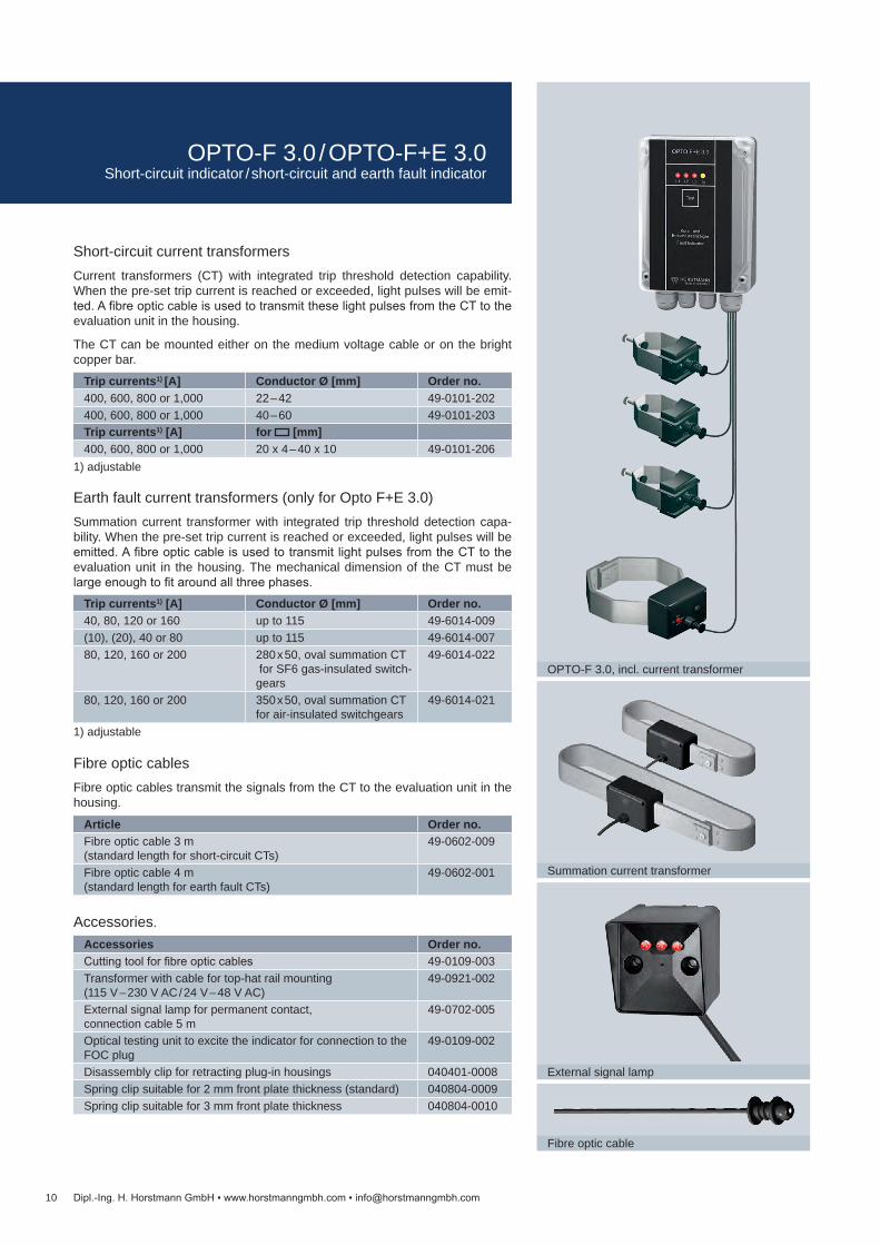
Trip currents1) [A] Conductor Ø [mm] Order no.400, 600, 800 or 1,000 22 – 42 49-0101-202400, 600, 800 or 1,000 40 – 60 49-0101-203Trip currents1) [A] for [mm]400, 600, 800 or 1,000 20 x 4 – 40 x 10 49-0101-206
Trip currents1) [A] Conductor Ø [mm] Order no.40, 80, 120 or 160 up to 115 49-6014-009(10), (20), 40 or 80 up to 115 49-6014-00780, 120, 160 or 200 280 x 50, oval summation CT
for SF6 gas-insulated switch-gears
49-6014-022
80, 120, 160 or 200 350 x 50, oval summation CT for air-insulated switchgears
49-6014-021
Article Order no.Fibre optic cable 3 m (standard length for short-circuit CTs)
49-0602-009
Fibre optic cable 4 m (standard length for earth fault CTs)
49-0602-001
Accessories Order no.Cutting tool for fibre optic cables 49-0109-003Transformer with cable for top-hat rail mounting (115 V – 230 V AC / 24 V – 48 V AC)
49-0921-002
External signal lamp for permanent contact, connection cable 5 m
49-0702-005
Optical testing unit to excite the indicator for connection to the FOC plug
49-0109-002
Disassembly clip for retracting plug-in housings 040401-0008Spring clip suitable for 2 mm front plate thickness (standard) 040804-0009Spring clip suitable for 3 mm front plate thickness 040804-0010
10
Summation current transformer
Fibre optic cable
External signal lamp
OPTO-F 3.0, incl. current transformer
Dipl.-Ing. H. Horstmann GmbH www.horstmanngmbh.com [email protected]
Short-circuit current transformersCurrent transformers (CT) with integrated trip threshold detection capability. When the pre-set trip current is reached or exceeded, light pulses will be emit-ted. A fibre optic cable is used to transmit these light pulses from the CT to the evaluation unit in the housing.
The CT can be mounted either on the medium voltage cable or on the bright copper bar.
Earth fault current transformers (only for Opto F+E 3.0)Summation current transformer with integrated trip threshold detection capa-bility. When the pre-set trip current is reached or exceeded, light pulses will be emitted. A fibre optic cable is used to transmit light pulses from the CT to the evaluation unit in the housing. The mechanical dimension of the CT must be large enough to fit around all three phases.
Fibre optic cablesFibre optic cables transmit the signals from the CT to the evaluation unit in the housing.
1) adjustable
1) adjustable
Accessories.
OPTO-F 3.0 / OPTO-F+E 3.0Short-circuit indicator / short-circuit and earth fault indicator
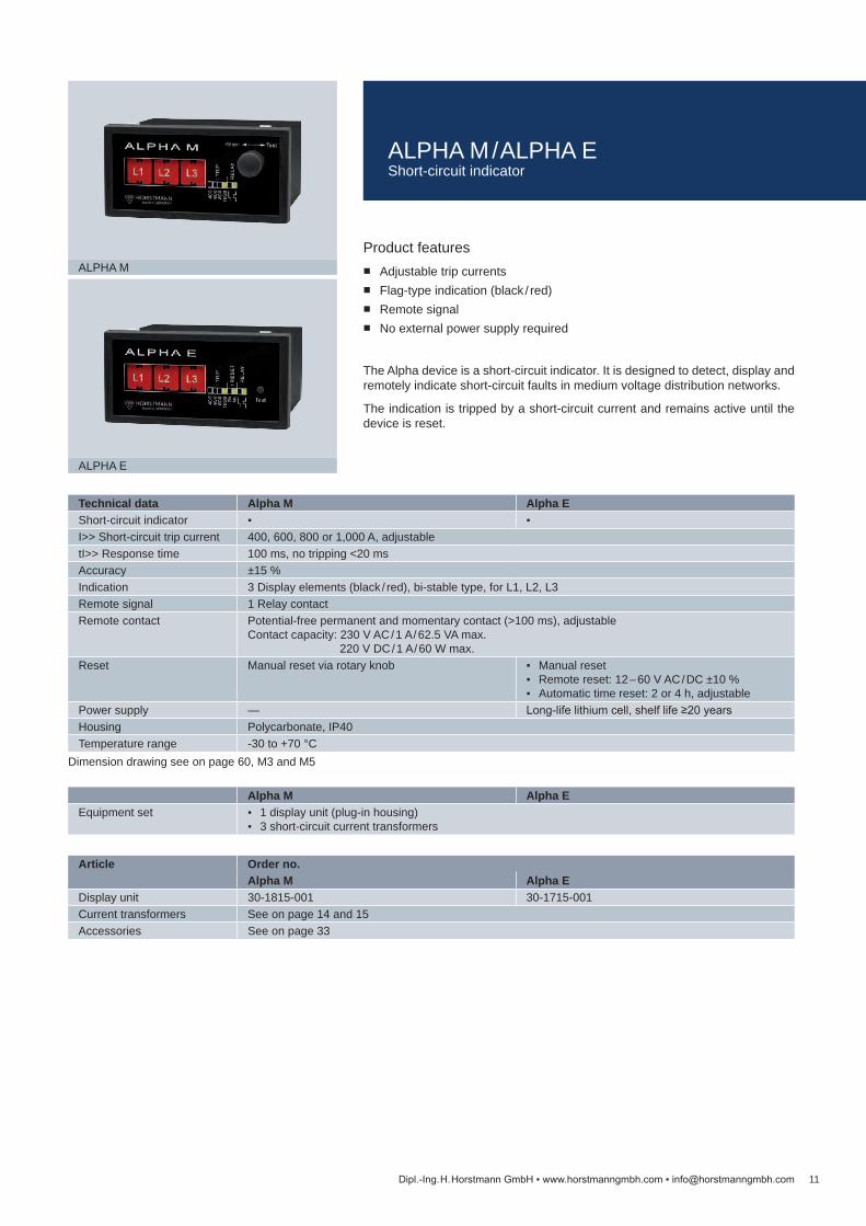
Technical data Alpha M Alpha EShort-circuit indicator I>> Short-circuit trip current 400, 600, 800 or 1,000 A, adjustabletI>> Response time 100 ms, no tripping <20 msAccuracy ±15 %Indication 3 Display elements (black / red), bi-stable type, for L1, L2, L3Remote signal 1 Relay contactRemote contact Potential-free permanent and momentary contact (>100 ms), adjustable
Contact capacity: 230 V AC / 1 A / 62.5 VA max. 220 V DC / 1 A / 60 W max.
Reset Manual reset via rotary knob Manual reset Remote reset: 12 – 60 V AC / DC ±10 % Automatic time reset: 2 or 4 h, adjustable
Power supply — Long-life lithium cell, shelf life ≥20 yearsHousing Polycarbonate, IP40Temperature range -30 to +70 °C
Alpha M Alpha EEquipment set 1 display unit (plug-in housing)
3 short-circuit current transformers
Article Order no.Alpha M Alpha E
Display unit 30-1815-001 30-1715-001Current transformers See on page 14 and 15Accessories See on page 33
11
ALPHA M
ALPHA E
Dipl.-Ing. H. Horstmann GmbH www.horstmanngmbh.com [email protected]
Dimension drawing see on page 60, M3 and M5
Product features Adjustable trip currents Flag-type indication (black / red) Remote signal No external power supply required
The Alpha device is a short-circuit indicator. It is designed to detect, display and remotely indicate short-circuit faults in medium voltage distribution networks.
The indication is tripped by a short-circuit current and remains active until the device is reset.
ALPHA M / ALPHA EShort-circuit indicator
12
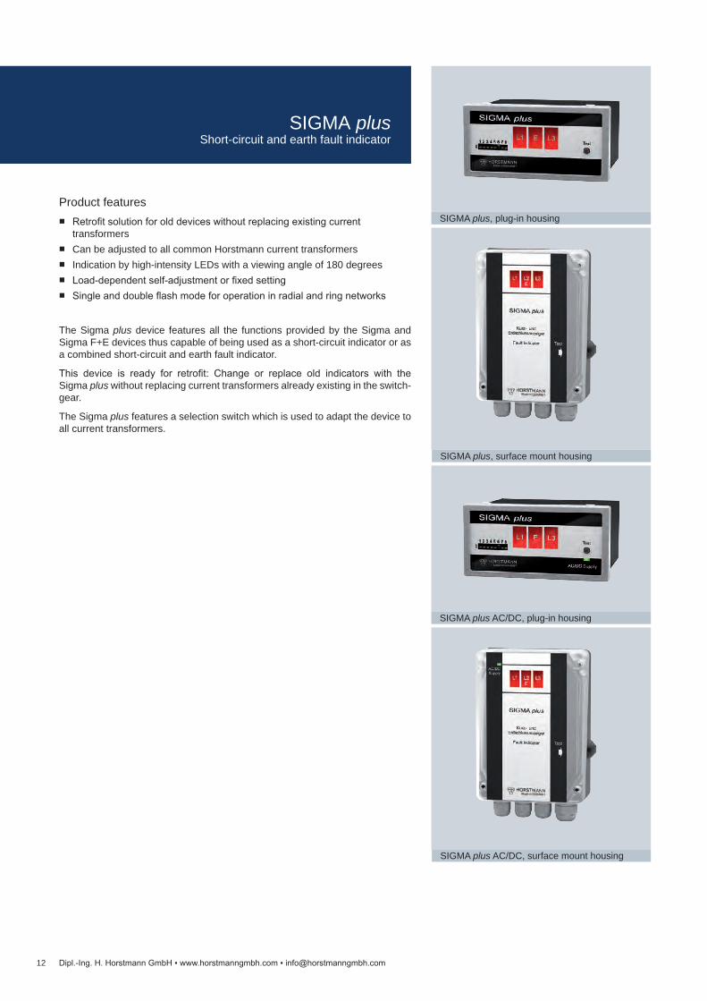
SIGMA plus, plug-in housing
SIGMA plus, surface mount housing
SIGMA plus AC/DC, plug-in housing
SIGMA plus AC/DC, surface mount housing
Dipl.-Ing. H. Horstmann GmbH www.horstmanngmbh.com [email protected]
Product features Retrofit solution for old devices without replacing existing current
transformers Can be adjusted to all common Horstmann current transformers Indication by high-intensity LEDs with a viewing angle of 180 degrees Load-dependent self-adjustment or fixed setting Single and double flash mode for operation in radial and ring networks
The Sigma plus device features all the functions provided by the Sigma and Sigma F+E devices thus capable of being used as a short-circuit indicator or as a combined short-circuit and earth fault indicator.
This device is ready for retrofit: Change or replace old indicators with the Sigma plus without replacing current transformers already existing in the switch-gear.
The Sigma plus features a selection switch which is used to adapt the device to all current transformers.
SIGMA plusShort-circuit and earth fault indicator

Technical data Sigma plusShort-circuit indicator Earth fault indicator I>> Short-circuit trip current (100), 200, 300, 400, 600, 800 or 1,000 A, fixed setting
Self-adjustment to load current (IL = load current): IL < 100 A I>> = 400 A, IL > 100 A I>> = 4 x IL
tI>> Response delay 40, 80, 200 or 300 msIE> Earth fault trip current 20, 40, 60, 80, 100, 120 or 160 AtIE> Response delay 80 or 160 msAccuracy ±15 %Indication Bright LED displays:
Short-circuit: 3 red phase-selective LEDs (L1, L2, L3) Short-circuit / earth fault: 3 red LEDs (L1, E, L3)
Reset Manual reset Automatic time reset: 2, 4, 8 or 24 h Remote reset Current restoration
Remote signal 2 Relay contactsRemote contact Potential-free permanent or momentary contact (1 s), adjustable
contact capacity: 230 V AC / 1 A / 62,5 VA max. 220 V DC / 1 A / 60 W max
Power supply Long-life lithium cell, shelf life ≥20 years, >1,000 h flashing timeHousing Polycarbonate, IP40 (plug-in housing), IP65 (surface mount housing)Temperature range -30 to +70 °C
Sigma plusEquipment set 1 display unit (plug-in/surface mount housing)
3 short-circuit current transformers or 2 short-circuit current transformers + 1 summation current transformer
Article Order no.Display unit in plug-in housing 37-3110-001Display unit in surface mount housing
37-3510-001
Display unit in plug-in housing with external power supply (AC / DC)
37-3120-001
Display unit in surface mount housing with external power supply (AC / DC)
37-3520-001
Current transformer See on page 14 and 15Accessories See on page 33
13Dipl.-Ing. H. Horstmann GmbH www.horstmanngmbh.com [email protected]
Dimension drawing see on page 60, M3 and on page 61, M7
SIGMA plusShort-circuit and earth fault indicator
For switchgear manufacturer
Type Dimensions [mm] Cable length [m] Order no.
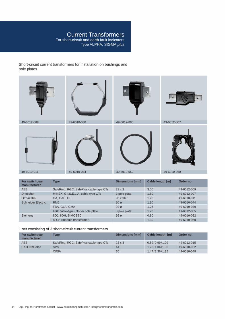
ABB SafeRing, RGC, SafePlus cable-type CTs 23 x 3 0.89 / 0.99 / 1.09 49-6012-015EATON / Holec SVS 44 1.22 / 1.06 / 1.06 49-6010-032
XIRIA 70 1.47 / 1.36 / 1.25 49-6010-048
For switchgear manufacturer
Type Dimensions [mm] Cable length [m] Order no.
ABB SafeRing, RGC, SafePlus cable-type CTs 23 x 3 3.00 49-6012-009Driescher MINEX, G.I.S.E.L.A. cable-type CTs 3 pole plate 1.50 49-6012-007Ormazabal GA, GAE, GE 96 x 96 1.20 49-6010-011Schneider Electric RM6 80 ø 1.10 49-6010-044
FBA, GLA, GMA 92 ø 1.26 49-6010-030FBX cable-type CTs for pole plate 3 pole plate 1.70 49-6012-005
Siemens 8DJ, 8DH, SIMOSEC 95 ø 0.80 49-6010-0528DJH (module transformer) 1.30 49-6010-060
14
49-6012-009 49-6012-00749-6012-00549-6010-030
49-6010-011 49-6010-06049-6010-05249-6010-044
Dipl.-Ing. H. Horstmann GmbH www.horstmanngmbh.com [email protected]
Short-circuit current transformers for installation on bushings and pole plates
1 set consisting of 3 short-circuit current transformers
Current TransformersFor short-circuit and earth fault indicators
Type ALPHA, SIGMA plus

Conductor Ø [mm] Cable length [m] Order no.15 – 52 3.00 49-6011-04015 – 52 6.00 49-6011-043
Type Conductor Ø [mm] Cable length [m] Order no.Summation current transformer for installation on cables
40 – 115 3 49-6013-016
Summation current transformer for air-insulated switchgears
350 x 50, oval 3 49-6013-027
Summation current transformer for SF6 gas-insulated switchgears
280 x 50, oval 3 49-6013-028
15
49-6011-040 / 49-6011-043
49-6013-016 49-6013-02849-6013-027
Dipl.-Ing. H. Horstmann GmbH www.horstmanngmbh.com [email protected]
Short-circuit current transformers for installation on insulated cables
Earth fault current transformersFor short-circuit and earth fault indicator type Sigma plus
Current TransformersFor short-circuit and earth fault indicators Type ALPHA, SIGMA plus
16
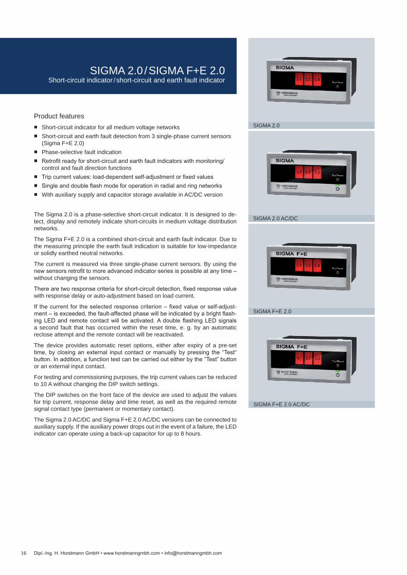
SIGMA 2.0
SIGMA 2.0 AC/DC
SIGMA F+E 2.0
SIGMA F+E 2.0 AC/DC
Dipl.-Ing. H. Horstmann GmbH www.horstmanngmbh.com [email protected]
Product features Short-circuit indicator for all medium voltage networks Short-circuit and earth fault detection from 3 single-phase current sensors
(Sigma F+E 2.0) Phase-selective fault indication Retrofit ready for short-circuit and earth fault indicators with monitoring/
control and fault direction functions Trip current values: load-dependent self-adjustment or fixed values Single and double flash mode for operation in radial and ring networks With auxiliary supply and capacitor storage available in AC/DC version
The Sigma 2.0 is a phase-selective short-circuit indicator. It is designed to de-tect, display and remotely indicate short-circuits in medium voltage distribution networks.
The Sigma F+E 2.0 is a combined short-circuit and earth fault indicator. Due to the measuring principle the earth fault indication is suitable for low-impedance or solidly earthed neutral networks.
The current is measured via three single-phase current sensors. By using the new sensors retrofit to more advanced indicator series is possible at any time – without changing the sensors.
There are two response criteria for short-circuit detection, fixed response value with response delay or auto-adjustment based on load current.
If the current for the selected response criterion – fixed value or self-adjust-ment – is exceeded, the fault-affected phase will be indicated by a bright flash-ing LED and remote contact will be activated. A double flashing LED signals a second fault that has occurred within the reset time, e. g. by an automatic reclose attempt and the remote contact will be reactivated.
The device provides automatic reset options, either after expiry of a pre-set time, by closing an external input contact or manually by pressing the “Test“ button. In addition, a function test can be carried out either by the “Test” button or an external input contact.
For testing and commissioning purposes, the trip current values can be reduced to 10 A without changing the DIP switch settings.
The DIP switches on the front face of the device are used to adjust the values for trip current, response delay and time reset, as well as the required remote signal contact type (permanent or momentary contact).
The Sigma 2.0 AC/DC and Sigma F+E 2.0 AC/DC versions can be connected to auxiliary supply. If the auxiliary power drops out in the event of a failure, the LED indicator can operate using a back-up capacitor for up to 8 hours.
SIGMA 2.0 / SIGMA F+E 2.0Short-circuit indicator / short-circuit and earth fault indicator

Article Order no.Sigma 2.0 Sigma 2.0 AC/DC Sigma F+E 2.0 Sigma F+E 2.0 AC/DC
Display unit 37-1111-101 37-1121-101 37-2111-101 37-2121-101Current sensors See on page 30 and 31Accessories See on page 33
Sigma 2.0 Sigma 2.0 AC/DC Sigma F+E 2.0 Sigma F+E 2.0 AC/DCEquipment set 1 display unit (plug-in housing)
3 short-circuit current sensors 1 display unit (plug-in housing) 3 short-circuit current sensors
Technical data Sigma 2.0 Sigma 2.0 AC/DC Sigma F+E 2.0 Sigma F+E 2.0 AC/DCShort-circuit indicator Earth fault indicator — — I>> Short-circuit trip current 200, 300, 400, 600, 800, 1,000 or 2,000 A, fixed setting
Self-adjustment to load current (IL = load current): IL < 100 A I>> = 400 A, IL > 100 A I>> = 4 x IL
tI>> Response delay 40 ms or 80 msIE> Earth fault trip current — — 20, 40, 60, 80, 100, 120 or 160 AtIE> Response delay — — 80 or 160 msAccuracy 5 % (0 – 630 A)
10 % (>630 A)Indication 3 red LEDs: 3 x short-circuit (L1, L2, L3) 3 red LEDs: Short-circuit 2 or 3 phases (L1, L2, L3)
Earth fault 1 phaseReset Manual reset
Automatic time reset: 1, 2, 4 or 8 h, adjustable Remote reset
Remote monitoring 1 potential-free relay contact 2 potential-free relay contactsRemote contact Potential-free permanent or momentary contact (1 s), adjustable
Contact capacity: 230 V AC / 1 A / 62.5 VA max. 220 V DC / 1 A / 60 W max.
Power supplyCT powered — —Internal power supply Long-life lithium cell,
shelf life ≥20 years, >900 h flashing time
Backup: capacitor, max. 8 h
Long-life lithium cell shelf life ≥20 years, >900 h flashing time
Backup: capacitor, max. 8 h
External auxiliary supply — 24–230 V AC/DC — 24–230 V AC/DCHousing Polycarbonate, IP40Temperature range -30 to +70 °C
17Dipl.-Ing. H. Horstmann GmbH www.horstmanngmbh.com [email protected]
Dimension drawing see on page 60, M3
SIGMA 2.0 / SIGMA F+E 2.0Short-circuit indicator / short-circuit and earth fault indicator
18
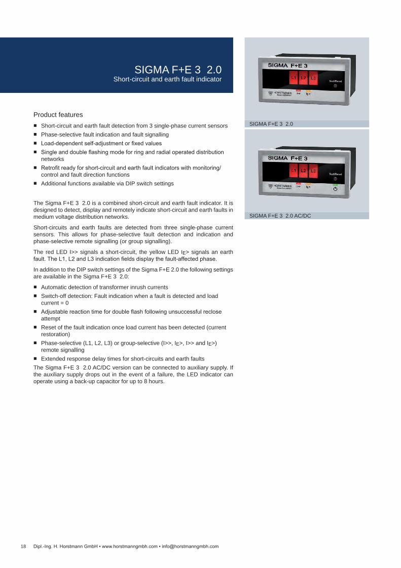
SIGMA F+E 3 2.0
SIGMA F+E 3 2.0 AC/DC
Dipl.-Ing. H. Horstmann GmbH www.horstmanngmbh.com [email protected]
Product features Short-circuit and earth fault detection from 3 single-phase current sensors Phase-selective fault indication and fault signalling Load-dependent self-adjustment or fixed values Single and double flashing mode for ring and radial operated distribution
networks Retrofit ready for short-circuit and earth fault indicators with monitoring/
control and fault direction functions Additional functions available via DIP switch settings
The Sigma F+E 3 2.0 is a combined short-circuit and earth fault indicator. It is designed to detect, display and remotely indicate short-circuit and earth faults in medium voltage distribution networks.
Short-circuits and earth faults are detected from three single-phase current sensors. This allows for phase-selective fault detection and indication and phase-selective remote signalling (or group signalling).
The red LED I>> signals a short-circuit, the yellow LED IE> signals an earth fault. The L1, L2 and L3 indication fields display the fault-affected phase.
In addition to the DIP switch settings of the Sigma F+E 2.0 the following settings are available in the Sigma F+E 3 2.0:
Automatic detection of transformer inrush currents Switch-off detection: Fault indication when a fault is detected and load
current = 0 Adjustable reaction time for double flash following unsuccessful reclose
attempt Reset of the fault indication once load current has been detected (current
restoration) Phase-selective (L1, L2, L3) or group-selective (I>>, IE>, I>> and IE>)
remote signalling Extended response delay times for short-circuits and earth faults
The Sigma F+E 3 2.0 AC/DC version can be connected to auxiliary supply. If the auxiliary supply drops out in the event of a failure, the LED indicator can operate using a back-up capacitor for up to 8 hours.
SIGMA F+E 3 2.0Short-circuit and earth fault indicator

Sigma F+E 3 2.0 (AC/DC)Equipment set 1 display unit (plug-in housing)
3 short-circuit current sensors
Article Order no.Sigma F+E 3 2.0 Sigma F+E 3 2.0 AC/DC
Display unit 37-5113-101 37-5123-101Current sensors See on page 30 and 31Accessories See on page 33
Technical data Sigma F+E 3 2.0 Sigma F+E 3 2.0 AC/DCShort-circuit indicator Earth fault indicator I>> Short-circuit trip current 200, 300, 400, 600, 800, 1,000 or 2,000 A, fixed setting
Self-adjustment as a function of the operating current (IL = load current): IL < 100 A I>> = 400 A, IL > 100 A I>> = 4 x IL, I>> max.= 2,000 A
tI>> Response delay 40, 80, 200 or 300 msIE> Earth fault trip current 20, 40, 60, 80, 100, 120 or 160 AtIE> Response delay 60, 80, 200 or 300 msAccuracy 5 % (0 – 630 A)
10 % (>630 A)Indication LED indicator fields:
3 red LEDs: phase-selective L1, L2, L3 1 red LED: short-circuit I>> 1 yellow LED: earth fault IE>
Reset Manual reset Automatic time reset: 2, 4, 8 or 24 h Remote reset Current restoration Restoration of auxiliary supply (only Sigma F+E 3 2.0 AC/DC)
Remote monitoring 3 potential-free relay contactsRemote contact Potential-free permanent or momentary contact (1 s), adjustable
Contact capacity: 230 V AC / 1 A / 62.5 VA max. 220 V DC / 1 A / 60 W max.
Power supplyCT powered —Internal power supply Long-life lithium cell, shelf life ≥20 years,
>900 h flashing timeBackup: capacitor, max. 8 h
External auxiliary supply — 24–230 V AC/DCHousing Polycarbonate, IP40Temperature range -30 to +70 °C
19Dipl.-Ing. H. Horstmann GmbH www.horstmanngmbh.com [email protected]
Dimension drawing see on page 60, M3
SIGMA F+E 3 2.0Short-circuit and earth fault indicator

20
SIGMA D++
SIGMA D
SIGMA D+
Dipl.-Ing. H. Horstmann GmbH www.horstmanngmbh.com [email protected]
Product features CT powered directional short-circuit and directional earth fault indicator for
all distribution networks / neutral point treatments Earth fault detection with up to 5 different earth fault detection methods,
also in combination Clear indication and signalling of fault direction Fully automatic voltage calibration Easy and flexible parameter setting via DIP switch or USB port Event memory for fault evaluation Multicolour LED status display Remote signalling via freely programmable relays Sigma Explorer Software: Commissioning and parameterisation via front
accessible USB port Special features of SIGMA D++
Only 3 single-phase current sensors needed for all earth fault detection methods
Wide-range power supply 24 V to 230 V AC/DC
The Sigma D series are combined directional short-circuit and directional earth fault indicators for medium voltage distribution networks. The devices are current sensor powered, thus no auxiliary supply is required. For the current measurement single-phase current sensors resp. a summation current sensor are required. The voltage information will be taken from an integrated voltage detecting system, either Wega 1.2 C, Wega 2.2 C or Wega 1.2 C vario. Option-ally, the voltage information can be taken from an HR interface or capacitive insulators.
The Sigma D+ and Sigma D++ provide additional earth fault detection methods for compensated and isolated neutral networks. The calculation or measure-ment of the summation current is chosen via DIP switches for all earth fault detection methods.
The variants differ in regard of the transient earth fault method.
SIGMA D+
For the transient earth fault method with the Sigma D+ a summation current sensor is mandatory, auxiliary supply is optional.
SIGMA D++
For the transient earth fault method only 3 single-phase current sensors are needed, but auxiliary supply is mandatory. The connection of a summation cur-rent sensor is optional.
The auxiliary supply is not needed if only the cos φ or sin φ method – without the transient earth fault method – is used for the fault direction indication.
SIGMA D++ / SIGMA D+ / SIGMA DDirectional fault indicator
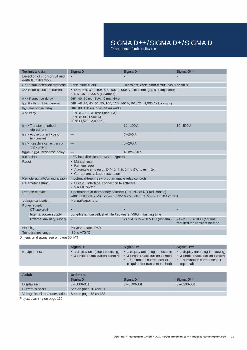
Technical data Sigma D Sigma D+ Sigma D++Detection of short-circuit and earth fault direction
Earth fault detection methods Earth short-circuit Transient, earth short-circuit, cos φ or sin φI>> Short-circuit trip current DIP: 200, 300, 400, 600, 800, 2,000 A (fixed settings), self-adjustment
SW: 50 – 2,000 A (1 A steps)tI>> Response delay DIP: 40, 80 ms; SW: 40 ms – 60 sIE> Earth fault trip current DIP: off, 20, 40, 60, 80, 100, 120, 160 A; SW: 20 – 1,000 A (1 A steps)tIE> Response delay DIP: 80, 160 ms; SW: 40 ms – 60 sAccuracy 3 % (0 – 630 A, resolution 1 A)
5 % (630 – 1,500 A) 10 % (1,500 – 2,000 A)
IET> Transient method,trip current
— 10 – 100 A 10 – 500 A
IEP> Active current cos φ,trip current
— 5 – 200 A
IEQ> Reactive current sin φ,trip current
— 5 – 200 A
tIEP> / tIEQ> Response delay — 40 ms – 60 sIndication LED fault direction arrows red / greenReset Manual reset
Remote reset Automatic time reset: DIP: 2, 4, 8, 24 h; SW: 1 min – 24 h Current and voltage restoration
Remote signal / Communication 4 potential-free, freely programmable relay contactsParameter setting USB 2.0 interface, connection to software
Via DIP switchRemote contact 4 permanent or momentary contacts (1 s), NC or NO (adjustable)
Contact capacity: 230 V AC / 1 A / 62.5 VA max.; 220 V DC / 1 A / 60 W max.Voltage calibration Manual / automaticPower supply
CT powered Internal power supply Long-life lithium cell, shelf life ≥20 years, >900 h flashing timeExternal auxiliary supply – 24 V AC / 24 – 60 V DC (optional) 24 – 230 V AC/DC (optional)
required for transient methodHousing Polycarbonate, IP40Temperature range -30 to +70 °C
Sigma D Sigma D+ Sigma D++Equipment set 1 display unit (plug-in housing)
3 single-phase current sensors 1 display unit (plug-in housing) 3 single-phase current sensors 1 summation current sensor
(required for transient method)
1 display unit (plug-in housing) 3 single-phase current sensors 1 summation current sensor
(optional)
Article Order no.Sigma D Sigma D+ Sigma D++
Display unit 37-6000-001 37-6100-001 37-6200-001Current sensors See on page 30 and 31Voltage interface / accessories See on page 32 and 33
21Dipl.-Ing. H. Horstmann GmbH www.horstmanngmbh.com [email protected]
Dimension drawing see on page 60, M3
Project planning on page 119
SIGMA D++ / SIGMA D+ / SIGMA DDirectional fault indicator
22
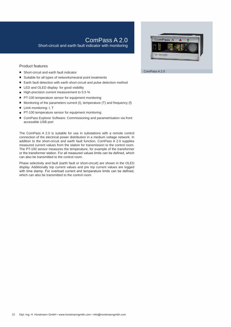
ComPass A 2.0
Dipl.-Ing. H. Horstmann GmbH www.horstmanngmbh.com [email protected]
Product features Short-circuit and earth fault indicator Suitable for all types of networks/neutral point treatments Earth fault detection with earth short-circuit and pulse detection method LED and OLED display: for good visibility High-precision current measurement to 0.5 % PT-100 temperature sensor for equipment monitoring Monitoring of the parameters current (I), temperature (T) and frequency (f) Limit monitoring: I, T PT-100 temperature sensor for equipment monitoring ComPass Explorer Software: Commissioning and parametrisation via front
accessible USB port
The ComPass A 2.0 is suitable for use in substations with a remote control connection of the electrical power distribution in a medium voltage network. In addition to the short-circuit and earth fault function, ComPass A 2.0 supplies measured current values from the station for transmission to the control room. The PT-100 sensor measures the temperature, for example of the transformer or the transformer station. For all measured values limits can be defined, which can also be transmitted to the control room.
Phase selectivity and fault (earth fault or short-circuit) are shown in the OLED display. Additionally trip current values and pre trip current values are logged with time stamp. For overload current and temperature limits can be defined, which can also be transmitted to the control room.
ComPass A 2.0Short-circuit and earth fault indicator with monitoring

Technical data ComPass A 2.0Short-circuit and earth fault indicator
Earth fault detection methods Earth short-circuitMeasured values / Indication Phase currents I1, I2, I3, IE with phase angle
Operating current, I1, I2, I3, IE ø15 min, I1, I2, I3 max. 24 h / 7 days / 365 days Maximum demand indicator I max. LR (last reset) I1, I2, I3 Frequency f Temperature T
Measurement accuracy phase currents up to 0.5 % / 0.5 A depending on the type of sensor (split-core or closed bushing type)I>> Short-circuit trip current 20 – 2,000 A tI>> Response delay 40 ms – 60 s IE> Earth short-circuit trip current 10 – 1,000 A tIE> Response delay 40 ms – 60 sLimit monitoring
I> Overload current 5 – 1,500 A; tI> Response delay: 40 ms – 60 sT< / T<< / T> / T>> Temperature -40 to +85 °C
Indication LED status display (multicolour) OLED display (multilingual)
Reset Manual or remote reset Automatic time reset: 1 min – 24 h Via RS485 / Modbus interface Auxiliary supply restoration, current restoration ComPass Explorer Software
Remote signal / Communication 4 potential-free relay contacts, freely configurable RS485 / Modbus interface
Parameter setting USB port with ComPass Explorer SoftwareRemote contact 4 permanent or momentary contacts, bistable,
NC or NO Contact capacity: 230 V AC / 1 A / 62.5 VA max.; 220 V DC / 1 A / 60 W max.
Binary inputs 2, potential-free, 1 s < t < 5 sPower supply
External auxiliary supply 24 – 230 V AC / DC (±10 %) Internal power supply Long-life lithium cell, shelf life ≥20 years, >1,000 h flashing time, >1,000 display activations
Housing Polycarbonate, IP50Temperature range -30 to +70 °C
ComPass A 2.0Equipment set 1 display unit (plug-in housing)
3 single-phase current sensors
Article Order no.Display unit 38-0152-001Current sensors See on page 30 and 31Accessories See on page 33
23Dipl.-Ing. H. Horstmann GmbH www.horstmanngmbh.com [email protected]
Dimension drawing see on page 60, M4
ComPass A 2.0Short-circuit and earth fault indicator with monitoring

24
ComPass A
Dipl.-Ing. H. Horstmann GmbH www.horstmanngmbh.com [email protected]
Product features Short-circuit and earth fault detection by 3 single-phase current sensors Phase-selective current monitor Multilingual OLED display, additional multicolour LED Remote indication via RS485/Modbus interface and 4 freely configurable
relay contacts Simple and intuitive operation, easy-to-read display
The ComPass A device is a combined short-circuit and earth fault indicator for medium voltage distribution networks with solidly or low-impendace earthed neutral system.
The device indicates all measuring results and parameter settings on a menu-controlled display. Via Modbus protocol the device can be parameterises and reports the fault events and measured data to the Scada. Additionally 4 relay contacts for Scada application are available.
When the previously set trip values are exceeded, the red LED will start flash-ing. By operating the rocker switch short-circuits or earth faults will be displayed in plain text format. The device saves the last 20 events along with date, time, and information on fault currents.
ComPass AShort-circuit and earth fault indicator

Technical data ComPass AShort-circuit indicator Earth fault indicator Measured values / indication Phase currents I1, I2, I3, IE with phase angle
Operating current, I1, I2, I3, IE ø15 min, I1, I2, I3 max. 24 h / 7 days / 365 days Maximum demand indicator I max. LR (last reset) I1, I2, I3 Frequency f
I>> Short-circuit trip current 10 – 2,000 A (1 A steps)tI>> Response delay 40 ms – 60 s (10 ms steps)IE> Earth fault trip current 20 – 1,000 A tIE> Response delay 40 ms – 60 sAccuracy 3 % (0 – 630 A, resolution 1 A)
5 % (630 – 1,500 A) 10 % (1,500 – 2,000 A)
Indication LED status display (multicolour) OLED display (multilingual)
Reset Manual or remote reset Automatic time reset: 1 min – 24 h Via RS485 / Modbus interface Auxiliary supply restoration Current restoration
Remote signal / Communication 4 potential-free relay contacts, freely configurable RS485 / Modbus interface
Remote contact 4 permanent or momentary contacts (1 s), NC or NO Contact capacity: 230 V AC / 1 A / 62.5 VA max.; 220 V DC / 1 A / 60 W max.
Power supplyExternal auxiliary supply 24 V – 230 V AC / DC (±10 %) Internal power supply Long-life lithium cell, shelf life ≥20 years, >1,000 h flashing time, >1,000 activations of the
displayHousing Polycarbonate, IP40Temperature range -30 to +70 °C
ComPass AEquipment set 1 display unit (plug-in housing)
3 single-phase current sensors
Article Order no.Display unit 38-0102-001Current sensors See on page 30 and 31Accessories See on page 33
25Dipl.-Ing. H. Horstmann GmbH www.horstmanngmbh.com [email protected]
Dimension drawing see on page 60, M3
ComPass AShort-circuit and earth fault indicator
26
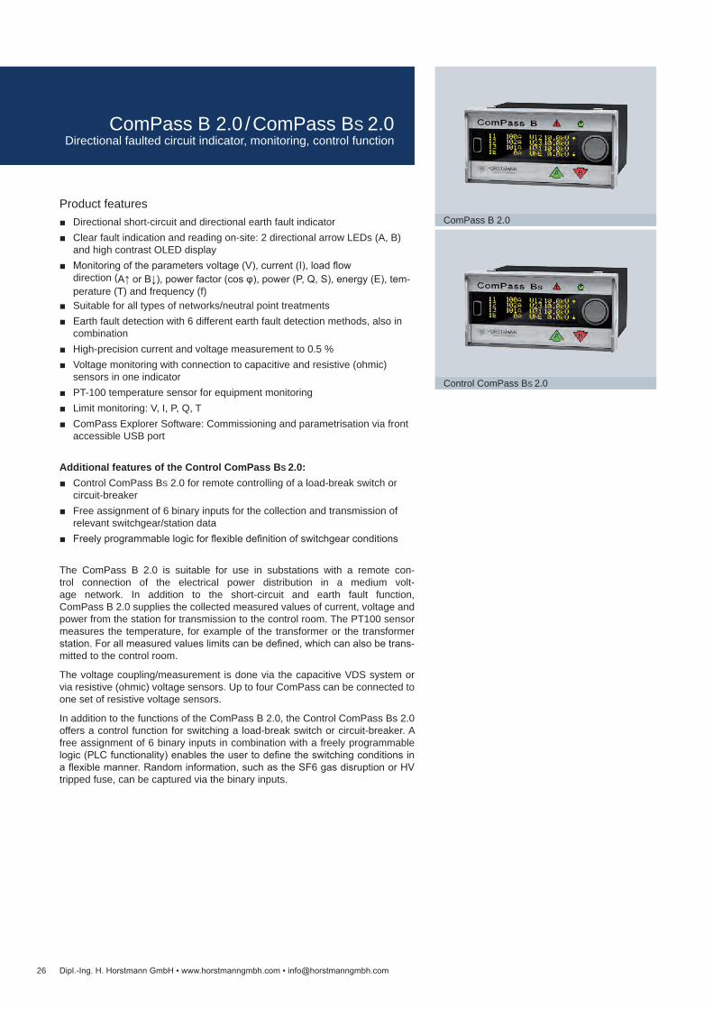
ComPass B 2.0
Control ComPass BS 2.0
Dipl.-Ing. H. Horstmann GmbH www.horstmanngmbh.com [email protected]
Product features Directional short-circuit and directional earth fault indicator Clear fault indication and reading on-site: 2 directional arrow LEDs (A, B)
and high contrast OLED display Monitoring of the parameters voltage (V), current (I), load flow
direction (A↑ or B↓), power factor (cos φ), power (P, Q, S), energy (E), tem-perature (T) and frequency (f)
Suitable for all types of networks/neutral point treatments Earth fault detection with 6 different earth fault detection methods, also in
combination High-precision current and voltage measurement to 0.5 % Voltage monitoring with connection to capacitive and resistive (ohmic)
sensors in one indicator PT-100 temperature sensor for equipment monitoring Limit monitoring: V, I, P, Q, T ComPass Explorer Software: Commissioning and parametrisation via front
accessible USB port
Additional features of the Control ComPass BS 2.0: Control ComPass BS 2.0 for remote controlling of a load-break switch or
circuit-breaker Free assignment of 6 binary inputs for the collection and transmission of
relevant switchgear/station data Freely programmable logic for flexible definition of switchgear conditions
The ComPass B 2.0 is suitable for use in substations with a remote con-trol connection of the electrical power distribution in a medium volt-age network. In addition to the short-circuit and earth fault function, ComPass B 2.0 supplies the collected measured values of current, voltage and power from the station for transmission to the control room. The PT100 sensor measures the temperature, for example of the transformer or the transformer station. For all measured values limits can be defined, which can also be trans-mitted to the control room.
The voltage coupling/measurement is done via the capacitive VDS system or via resistive (ohmic) voltage sensors. Up to four ComPass can be connected to one set of resistive voltage sensors.
In addition to the functions of the ComPass B 2.0, the Control ComPass Bs 2.0 offers a control function for switching a load-break switch or circuit-breaker. A free assignment of 6 binary inputs in combination with a freely programmable logic (PLC functionality) enables the user to define the switching conditions in a flexible manner. Random information, such as the SF6 gas disruption or HV tripped fuse, can be captured via the binary inputs.
ComPass B 2.0 / ComPass BS 2.0Directional faulted circuit indicator, monitoring, control function

ComPass B 2.0 ComPass BS 2.0Equipment set 1 display unit (plug-in housing) + 3 single-phase current sensors
(combination with summation sensor possible: 3+1 or 2+1)
Article Order no.ComPass B 2.0 ComPass BS 2.0
Display unit 38-4150-001 38-4153-001Current sensors See on page 30 and 31Voltage interface / accessories See on page 32 and 33
Technical data ComPass B 2.0 ComPass BS 2.0Detection of short-circuit and earth fault direction
Earth fault detection methods Permanent, earth short-circuit, transient, cos φ and sin φControl system/freely programmable logic —
Measured values / Indication Phase currents I1, I2, I3, IE with phase angle Phase-to-earth voltage V1, V2, V3, VNE and phase-to-phase voltage V12, V23, V31, VNE
with phase angle Load flow direction A↑ or B↓ P, Q, S and cos φ (power factor) (P1,2,3, Q 1,2,3, S 1,2,3, cos φ 1,2,3 via RS485) Amount of active energy, separate for load flow direction A↑ or B↓; additionally per phase Operating current, I1,2,3 ø15 min, Imax. 24 h/7 days/365 days,
max. demand indicator I max. LR Power frequency f Temperature T
Measurement accuracy phase currents Up to 0.5 % / 0.5 A depending on the type of sensor (split-core or closed bushing type)Measurement accuracy voltages Up to 0.5 % in the range of 80 – 120 % / Vnom, depending on sensor type (resistive or capacitive)I>> Short-circuit trip current 20 – 2,000 A; tI>> Response delay: 40 ms – 60 sVNE> Permanent earth fault trip values 1 – 100 %; tVNE> Response delay: 40 ms – 60 sIES> / IES>> Earth short-circuit trip current 10 – 1,000 A; tIES> / tIES>> Response delay: 40 ms – 60 sIET> Transient method 1 – 500 A IEP> Active current cos φ / IEQ> Reactive current sin φ
1 – 200 A; tIEP> / tIEQ> Response delay: 40 ms – 60 s
Limit monitoringI> Overload current 5 – 1,500 A;tI> Response delay: 40 ms – 60 sV> Overvoltage 100 – 200 %; tV> Response delay: 40 ms – 60 sV< Undervoltage 1 – 100 %; tV< Response delay: 40 ms – 60 sP> / P>> Active power 1 – 30,000 kW; tP> / tP>> Response delay: 40 ms – 60 sQ> / Q>> Reactive power 1 – 30,000 kW; tQ> / tQ>> Response delay: 40 ms – 60 sT< / T<< / T> / T>> Temperature -40 to +85 °C
Indication LED fault direction and status indicators (multicolour); OLED display (multilingual)Reset Local, remote, automatic time reset: 1 min – 24 h
Via RS485 / Modbus interface Auxiliary supply restoration, voltage and current restoration ComPass Explorer Software
Remote signal / Communication 4 potential-free, freely programmable relay contacts RS485 / Modbus interface
Parameter setting USB port with ComPass Explorer SoftwareRemote contact 4 permanent or momentary contacts,
bistable, NC /NO Contact capacity: 230 V AC/1 A/62.5 VA max 220 V DC/1 A/60 W max.
4 permanent or momentary contacts, monostable, NC /NO Contact capacity: 250 V AC/6 A; 30 V DC/ 6 A, resistive load
Binary inputs 2, potential-free, 1 s < t < 5 s 6, freely programmable, max. 30 V DCPower supply
External auxiliary supply 24 – 230 V AC / DC (±10 %) Internal power supply Long-life lithium cell, shelf life ≥20 years, >1,000 h flashing time, >1.000 display activations
Housing Polycarbonate, IP50Temperature range -30 to +70 °C
27Dipl.-Ing. H. Horstmann GmbH www.horstmanngmbh.com [email protected]
Dimension drawing see on page 60, M4
Project planning on page 119
ComPass B 2.0 / ComPass BS 2.0Directional faulted circuit indicator, monitoring, control function
28
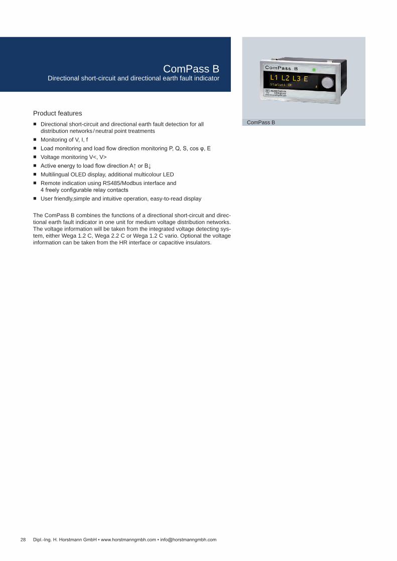
ComPass B
Dipl.-Ing. H. Horstmann GmbH www.horstmanngmbh.com [email protected]
Product features Directional short-circuit and directional earth fault detection for all
distribution networks / neutral point treatments Monitoring of V, I, f Load monitoring and load flow direction monitoring P, Q, S, cos φ, E Voltage monitoring V<, V> Active energy to load flow direction A↑ or B↓ Multilingual OLED display, additional multicolour LED Remote indication using RS485/Modbus interface and
4 freely configurable relay contacts User friendly,simple and intuitive operation, easy-to-read display
The ComPass B combines the functions of a directional short-circuit and direc-tional earth fault indicator in one unit for medium voltage distribution networks. The voltage information will be taken from the integrated voltage detecting sys-tem, either Wega 1.2 C, Wega 2.2 C or Wega 1.2 C vario. Optional the voltage information can be taken from the HR interface or capacitive insulators.
ComPass BDirectional short-circuit and directional earth fault indicator
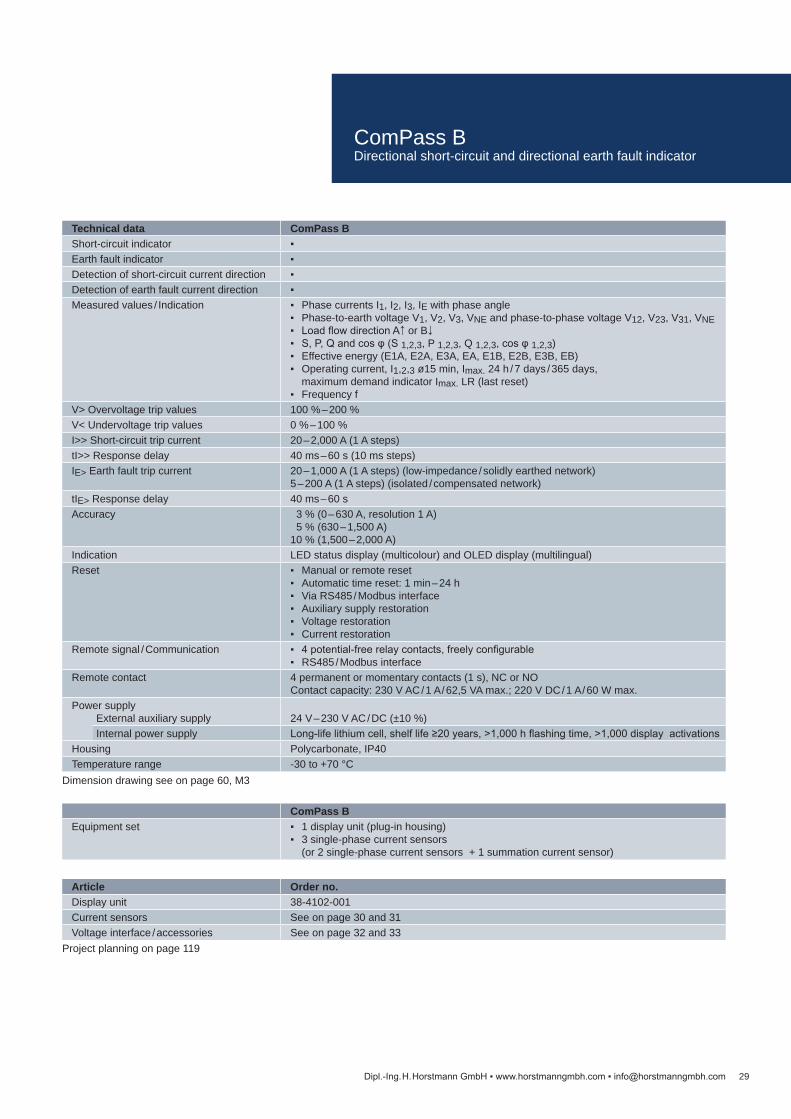
Technical data ComPass BShort-circuit indicator Earth fault indicator Detection of short-circuit current direction Detection of earth fault current direction Measured values / Indication Phase currents I1, I2, I3, IE with phase angle
Phase-to-earth voltage V1, V2, V3, VNE and phase-to-phase voltage V12, V23, V31, VNE Load flow direction A↑ or B↓ S, P, Q and cos φ (S 1,2,3, P 1,2,3, Q 1,2,3, cos φ 1,2,3) Effective energy (E1A, E2A, E3A, EA, E1B, E2B, E3B, EB) Operating current, I1,2,3 ø15 min, Imax. 24 h / 7 days / 365 days,
maximum demand indicator Imax. LR (last reset) Frequency f
V> Overvoltage trip values 100 % – 200 %V< Undervoltage trip values 0 % – 100 %I>> Short-circuit trip current 20 – 2,000 A (1 A steps)tI>> Response delay 40 ms – 60 s (10 ms steps)IE> Earth fault trip current 20 – 1,000 A (1 A steps) (low-impedance / solidly earthed network)
5 – 200 A (1 A steps) (isolated / compensated network)tIE> Response delay 40 ms – 60 sAccuracy 3 % (0 – 630 A, resolution 1 A)
5 % (630 – 1,500 A) 10 % (1,500 – 2,000 A)
Indication LED status display (multicolour) and OLED display (multilingual)Reset Manual or remote reset
Automatic time reset: 1 min – 24 h Via RS485 / Modbus interface Auxiliary supply restoration Voltage restoration Current restoration
Remote signal / Communication 4 potential-free relay contacts, freely configurable RS485 / Modbus interface
Remote contact 4 permanent or momentary contacts (1 s), NC or NO Contact capacity: 230 V AC / 1 A / 62,5 VA max.; 220 V DC / 1 A / 60 W max.
Power supplyExternal auxiliary supply 24 V – 230 V AC / DC (±10 %) Internal power supply Long-life lithium cell, shelf life ≥20 years, >1,000 h flashing time, >1,000 display activations
Housing Polycarbonate, IP40Temperature range -30 to +70 °C
ComPass BEquipment set 1 display unit (plug-in housing)
3 single-phase current sensors (or 2 single-phase current sensors + 1 summation current sensor)
Article Order no.Display unit 38-4102-001Current sensors See on page 30 and 31Voltage interface / accessories See on page 32 and 33
29Dipl.-Ing. H. Horstmann GmbH www.horstmanngmbh.com [email protected]
Dimension drawing see on page 60, M3
Project planning on page 119
ComPass BDirectional short-circuit and directional earth fault indicator
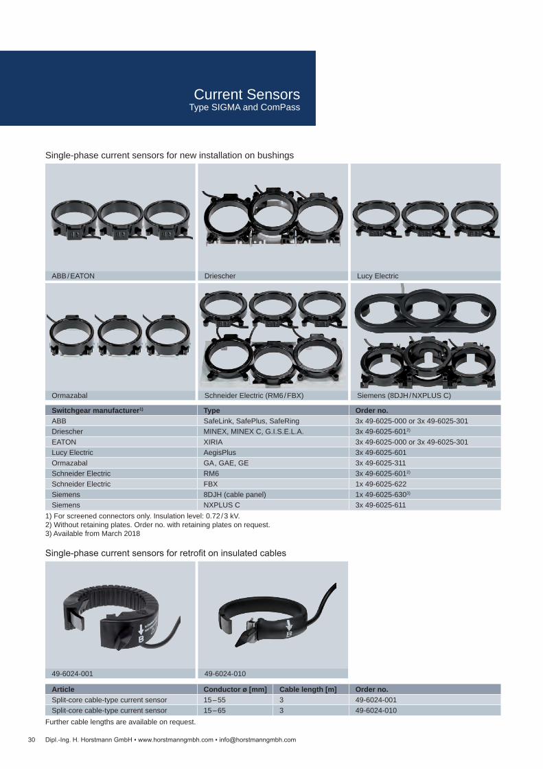
Switchgear manufacturer1) Type Order no.ABB SafeLink, SafePlus, SafeRing 3x 49-6025-000 or 3x 49-6025-301Driescher MINEX, MINEX C, G.I.S.E.L.A. 3x 49-6025-6012)
EATON XIRIA 3x 49-6025-000 or 3x 49-6025-301Lucy Electric AegisPlus 3x 49-6025-601Ormazabal GA , GAE, GE 3x 49-6025-311Schneider Electric RM6 3x 49-6025-6012)
Schneider Electric FBX 1x 49-6025-622Siemens 8DJH (cable panel) 1x 49-6025-6303)
Siemens NXPLUS C 3x 49-6025-611
Article Conductor ø [mm] Cable length [m] Order no.Split-core cable-type current sensor 15 – 55 3 49-6024-001Split-core cable-type current sensor 15 – 65 3 49-6024-010
30
ABB / EATON Driescher Lucy Electric
Ormazabal Schneider Electric (RM6 / FBX) Siemens (8DJH / NXPLUS C)
49-6024-001 49-6024-010
Dipl.-Ing. H. Horstmann GmbH www.horstmanngmbh.com [email protected]
1) For screened connectors only. Insulation level: 0.72 / 3 kV.2) Without retaining plates. Order no. with retaining plates on request. 3) Available from March 2018
Single-phase current sensors for new installation on bushings
Single-phase current sensors for retrofit on insulated cables
Further cable lengths are available on request.
Current SensorsType SIGMA and ComPass

Article Inner ø [mm] Cable length [m] Order no.Split-core summation sensor 150 4 49-6023-005Split-core summation sensor 220 – 250 4 49-6023-020
Article For T connector sets Order no.3 voltage sensors, long cone; shielded 2 pole cable with connector, 3.5 m; incl. connecting terminal and termination resistor
Nexans: (K) 400TB Cellpack: CTS Südkabel: SEHDT 13, SEHDT 23
38-9100-013
3 voltage sensors, short cone; shielded 2 pole cable with connector, 3.5 m; incl. connecting terminal and termination resistor
Nkt: CB-24, CC-24 Raychem: RSTI-58xx, RSTI-CC-58xx
38-9100-017
Connecting cable set for providing voltage information from ComPass B 2.0 to ComPass B 2.0; 1.0 m
49-0509-311
Article Order no.3 voltage sensors with adapters for A cones; shielded 2 pole cable with connector, 6 m; incl. connecting terminal and termination resistor
38-9100-026
Connecting cable set for providing voltage information from ComPass B 2.0 to ComPass B 2.0; 1.0 m 49-0509-311
31
49-6023-005 49-6023-020
38-9100-026
38-9100-013 38-9100-017
Dipl.-Ing. H. Horstmann GmbH www.horstmanngmbh.com [email protected]
Earth fault current sensors for installation on insulated cables
Voltage sensors for installation in connector setsfor short-circuit and earth fault indicators type ComPass B 2.0, ComPass BS 2.0
Adapter and voltage sensors for direct installation on A cone in the switchgear or on the transformerfor short-circuit and earth fault indicators type ComPass B 2.0, ComPass BS 2.0
Further cable lengths are available on request.
Current SensorsType SIGMA D+ / D++ and ComPass B series

Article Order no.Wega 1.2 C See on page 83Wega 2.2 C See on page 85Wega 1.2 C vario See on page 84Set of connection cables (ComPass B – Wega X.2 C)
49-0509-0xx1)
Set of connection cables (Sigma D / D+ / D++ – Wega X.2 C ComPass B 2.0 / BS 2.0 – Wega X.2 C)
49-0509-1xx1)
Article Order no.Wega 1.2 C vario See on page 84Wega mounting kit (housing / magnet / connection cable)
51-1550-900
Article Order no.HR interface cable to match specific switchgear types for ComPass B
49-0509-0xx2)
HR interface cable to match specific switchgear types for Sigma D / D+ / D++, ComPass B 2.0 / BS 2.0
49-0509-2xx2)
Article Order no.Interface cable to match specific switchgear types for ComPass B
49-0509-0xx3)
Interface cable to match specific switchgear types for Sigma D / D+ / D++, ComPass B 2.0 / BS 2.0
49-0509-2xx3)
32
WEGA 1.2 C
HR interface cable (example)
WEGA 1.2 C vario
WEGA 2.2 C
Set of connection cables (example)
WEGA 1.2 C vario with mounting kit
Interface cable for capacitive insulators (example)
Dipl.-Ing. H. Horstmann GmbH www.horstmanngmbh.com [email protected]
3) For a customised application the following data are required: Switchgear type and compartment Operating voltage of the installation (Vnom) Cable length of the interface cable
Direct connection capacitive insulator
2) For a customised application the following data are required: Switchgear type and compartment Operating voltage of the installation (Vnom) Cable length of the HR interface cable Short-circuit current of HR socket Current measured via HO-M adapter of HR socket
Direct connection HR interface
Systems solution Wega to HR interface
1) For a customised application the following data are required: Cable length of the connection cables Connection to Wega (AMP or flat connector)
Systems solution Wega
Voltage interfacesFor directional fault indicators
SIGMA D series and ComPass B series

Article Order no.Tablet for parameter setting during installation or monitoring, incl. cover, pencil, power supply and USB cable
49-6022-010
Article Order no.Disassembly clip 040401-0008Disassembly clip ComPass B 2.0 / BS 2.0 040408-0005Spring clip suitable for 2 mm front plate thickness (standard)
040804-0009
Spring clip suitable for 3 mm front plate thickness
040804-0010
Article Order no.Wall-mounted housing including earthing bar 290 x 74 x 200 mm (W x H x D)
V49-9001-007-001
Wall-mounted housing including earthing bar 125 x 175 x 125 mm (W x H x D)
V49-9001-004-001
Wall-mounted housing 125 x 75 x 125 mm (W x H x D) Bottom cable entry Rear cable entry
49-9001-001 49-9001-002
Wall-mounted housing 125 x 75 x 75 mm (W x H x D) 49-9001-006
Article Order no.External signal lamp with 3 LEDs, 5 m connection cable, for permanent contact, with battery
49-0702-005
External signal lamp with 3 LEDs, 10 m connection cable, for permanent contact, with battery
49-0702-010
External signal lamp „bicolor“ with 3 LEDs (red / green), 3 m connection cable, with battery
49-0706-001
External signal lamp „bicolor“ for connection of fibre optic cables, 1 LED (rot / green),2 m connection cable, with battery
49-0704-001
33
Installation system
V49-9001-007-001
49-0704-001
49-0702-005 and 49-0706-001
49-9001-006
49-9001-001 / 49-9001-002
V49-9001-004-001
Dipl.-Ing. H. Horstmann GmbH www.horstmanngmbh.com [email protected]
Installation systemfor Sigma D series and ComPass series
Accessoriesfor plug-in housings
Wall-mounted housingsfor the installation of short-circuit and earth fault indicators as well as integrated voltage detecting systems outside the switchgear
External signal lampfor installation outside the switchgear
AccessoriesFor short-circuit and earth fault indicators and integrated voltage detecting systems
34
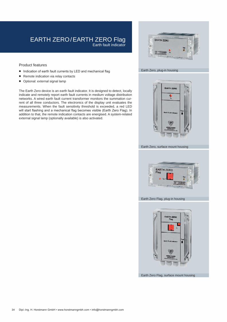
Earth Zero, plug-in housing
Earth Zero, surface mount housing
Earth Zero Flag, plug-in housing
Earth Zero Flag, surface mount housing
Dipl.-Ing. H. Horstmann GmbH www.horstmanngmbh.com [email protected]
Product features Indication of earth fault currents by LED and mechanical flag Remote indication via relay contacts Optional: external signal lamp
The Earth Zero device is an earth fault indicator. It is designed to detect, locally indicate and remotely report earth fault currents in medium voltage distribution networks. A wired earth fault current transformer monitors the summation cur-rent of all three conductors. The electronics of the display unit evaluates the measurements. When the fault sensitivity threshold is exceeded, a red LED will start flashing and a mechanical flag becomes visible (Earth Zero Flag). In addition to that, the remote indication contacts are energised. A system-related external signal lamp (optionally available) is also activated.
EARTH ZERO / EARTH ZERO FlagEarth fault indicator

Technical data Earth Zero Earth Zero Type FlagEarth fault indicator IE> Earth fault trip current 25, 50, 75 or 100 A1)
tIE> Response delay 80 or 160 ms1)
Accuracy ±15 %Indication 1 red LED, flash rate 2 s 1 red LED, flash rate 2 s + mechanical flagReset Manual reset
Automatic time reset: 2, 4 or 8 h Voltage restoration (110 – 240 V AC)
Remote signal 1 Relay contact and input for external signal lampRemote contact Potential-free permanent or momentary contact (1 s), adjustable
Contact capacity: 230 V AC / 1 A / 62.5 VA max. 220 V DC / 1 A / 60 W max.
Power supply Long-life lithium cell, shelf life ≥20 years,>1,200 h total flashing time (>500 h when using the external signal lamp)
Housing Polycarbonate, IP40 (plug-in housing), IP65 (surface mount housing)Temperature range -30 to +70 °C
Earth Zero Earth Zero Type FlagEquipment set 1 display unit
1 summation current transformer
Article Order no.Earth Zero Earth Zero Type Flag
Display unit in plug-in housing 32-0513-001 32-0512-002Display unit in surface mount housing
32-0503-001 32-0502-002
Summation current transform-er, 3 m connection cable
49-6013-029
External signal lamp, 3 LEDs, 10 m cable, with battery
49-0702-010
External signal lamp, 3 LEDs, 15 m cable, with battery
49-0702-015
35
Summation current transformer
External signal lamp
Dipl.-Ing. H. Horstmann GmbH www.horstmanngmbh.com [email protected]
1) Further trip currents on requestDimension drawing see on page 60, M6 and on page 61, M7
EARTH ZERO / EARTH ZERO FlagEarth fault indicator

36
EARTH 4.0, surface mount housing
Summation current transformer
External signal lamp
Dipl.-Ing. H. Horstmann GmbH www.horstmanngmbh.com [email protected]
Product features Indication of earth fault currents by LED and mechanical flag Remote indication, test and reset via relay contacts Battery status indication and remote indication via relay contact
The Earth 4.0 device is an earth fault indicator. It is designed to detect, locally indicate and remotely report earth fault currents in medium voltage distribution networks. A wired earth fault current transformer monitors the summation cur-rent of all three conductors. The electronics of the display unit evaluates the measurements. When the fault sensitivity threshold is exceeded, a red LED will start flashing and a mechanical flag becomes visible. In addition to that, the re-mote indication contacts are energised. A system-specific external signal lamp is optionally available.
EARTH 4.0Earth fault indicator

Technical data Earth 4.0Earth fault indicator IE> Earth fault trip current 25, 50, 60 or 80 A, adjustable1)
tIE> Response delay 80 or 160 ms1)
Accuracy ±10 %Indication 1 red LED, flash rate 2 s
1 yellow LED (battery status), flash rate 2 s Mechanical flag
Test Manual by button located at the side Remote contact
Reset Manual by button located at the side Remote contact Automatic time reset: after expiry of 1, 2, 4, 8 h Voltage restoration (220 – 240 V AC, ≥10 %)
Remote signal 2 relay contacts (change over) for earth fault indication 1 relay contact (change over) for battery status indication
Remote contact Permanent or momentary contact (1 s), adjustable Contact capacity: 230 V AC / 1 A / 62.5 VA max. 220 V DC / 1 A / 60 W max.
Power supply Long-life lithium cell, shelf life ≥20 years, total flashing time ≥1,200 h
Housing Polycarbonate, IP65 (surface mount housing)Temperature range -30 to +70 °C
Article Order no.Display unit in surface mount housing
32-0504-115
Summation current transform-er, 3 m connection cable
49-6013-029
External signal lamp, 3 LEDs, 10 m cable, with battery
49-0702-010
External signal lamp, 3 LEDs, 15 m cable, with battery
49-0702-015
Earth 4.0Equipment set 1 display unit (surface mount housing)
1 summation current transformer
37Dipl.-Ing. H. Horstmann GmbH www.horstmanngmbh.com [email protected]
Dimension drawing see on page 61, M71) Further trip currents on request
EARTH 4.0Earth fault indicator
38
NAVIGATOR-LM (≤46 kV)
NAVIGATOR-LM HV (≤161 kV)
Test/Reset magnet
Current [A]10 100Current / Time characteristic
1000 100000,01
0.1
1
10
Tim
e [s
]
Dipl.-Ing. H. Horstmann GmbH www.horstmanngmbh.com [email protected]
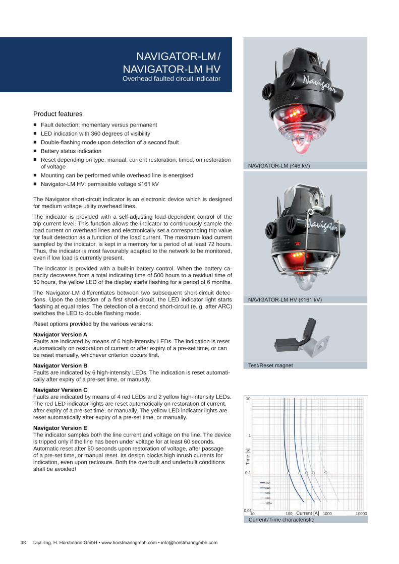
Product features Fault detection; momentary versus permanent LED indication with 360 degrees of visibility Double-flashing mode upon detection of a second fault Battery status indication Reset depending on type: manual, current restoration, timed, on restoration
of voltage Mounting can be performed while overhead line is energised Navigator-LM HV: permissible voltage ≤161 kV
The Navigator short-circuit indicator is an electronic device which is designed for medium voltage utility overhead lines.
The indicator is provided with a self-adjusting load-dependent control of the trip current level. This function allows the indicator to continuously sample the load current on overhead lines and electronically set a corresponding trip value for fault detection as a function of the load current. The maximum load current sampled by the indicator, is kept in a memory for a period of at least 72 hours. Thus, the indicator is most favourably adapted to the network to be monitored, even if low load is currently present.
The indicator is provided with a built-in battery control. When the battery ca-pacity decreases from a total indicating time of 500 hours to a residual time of 50 hours, the yellow LED of the display starts flashing for a period of 6 months.
The Navigator-LM differentiates between two subsequent short-circuit detec-tions. Upon the detection of a first short-circuit, the LED indicator light starts flashing at equal rates. The detection of a second short-circuit (e. g. after ARC) switches the LED to double flashing mode.
Reset options provided by the various versions:
Navigator Version A Faults are indicated by means of 6 high-intensity LEDs. The indication is reset automatically on restoration of current or after expiry of a pre-set time, or can be reset manually, whichever criterion occurs first.
Navigator Version B Faults are indicated by 6 high-intensity LEDs. The indication is reset automati-cally after expiry of a pre-set time, or manually.
Navigator Version C Faults are indicated by means of 4 red LEDs and 2 yellow high-intensity LEDs. The red LED indicator lights are reset automatically on restoration of current, after expiry of a pre-set time, or manually. The yellow LED indicator lights are reset automatically after expiry of a pre-set time, or manually.
Navigator Version E The indicator samples both the line current and voltage on the line. The device is tripped only if the line has been under voltage for at least 60 seconds. Automatic reset after 60 seconds upon restoration of voltage, after passage of a pre-set time, or manual reset. Its design blocks high inrush currents for indication, even upon reclosure. Both the overbuilt and underbuilt conditions shall be avoided!
NAVIGATOR-LM / NAVIGATOR-LM HVOverhead faulted circuit indicator

Technical data Navigator-LM / Navigator-LM HVVersion A Version B Version C Version E
Trip current ≥100 A / ≥100 ms, load-dependent self-adjustment (see current/time characteristic)Accuracy ±10 % at 20 °CSelf-adjustment ≥20 A load currentTrip factor 4 – 6 x load current (see current/time characteristic)Adjustment delay ≥50 s load current flow timeHolding time of self-adjustment 72 hIndicators (short-circuit /earth fault)
4 red LEDs (>5,000 mcd or 7,000 mLm per piece) 2 yellow LEDs
Visibility >50 m / day, >150 m / night / 360 degrees of visibilityFlash rate 30 flashes per minute, total indication time >500 hReset Manual reset by mean of a permanent magnet
Automatic time reset: 4 h ±10 % (2 or 8 h)Current restoration>3 A load current
— Current restoration>3 A load current
—
— — — Voltage restoration, line voltage ≥5 kV
Power supply Lithium cells, replaceable, shelf life ≥20 yearsBattery check 1 yellow LED, flash rate: 6 per minute, 0.5 yearsMax. permissible voltage Navigator-LM: ≤46 kV / 50 Hz or 60 Hz
Navigator-LM HV: ≤161 kV / 50 Hz or 60 HzWithstand current Navigator-LM: 25 kA / 200 ms
Navigator-LM HV: 40 kA / 1 sCable diameter range Navigator-LM: 4 – 29 mm (0.16 – 1.15")
Navigator-LM HV: 13 – 36 mm (0.51 – 1.42")Influence No influence by vicinal power lines with a horizontal distance of at least 250 mm from the indicatorHousing UV-resistant polycarbonate / polyamide, IP68
Clamping mechanism: stainless steelTemperature range -30 to +70 °C (IEEE 495 -40 to +85 °C)
Article Order no.Version A Version B Version C Version E
Navigator-LM 41-2x01-1xx 41-2x01-2xx 41-2x01-3xx 41-2x01-5xxNavigator-LM HV 41-2x08-1xx 41-2x08-2xx 41-2x08-3xx 41-2x08-5xxMagnet (test and reset) 49-6001-002Hot stick with hook See on page 107
39Dipl.-Ing. H. Horstmann GmbH www.horstmanngmbh.com [email protected]
Navigator PM without self-adjustment facility provided with fixed trip currents (e. g. 800 A / 100 ms) available ex works after consultation with the manufacturer.
Dimension drawing see on page 61, M8
NAVIGATOR-LM / NAVIGATOR-LM HVOverhead faulted circuit indicator

40
SMART NAVIGATOR / SMART NAVIGATOR HV
Dipl.-Ing. H. Horstmann GmbH www.horstmanngmbh.com [email protected]
Product features
Event based data reports: Fault detection; momentary versus permanent Fault current magnitude Fault duration Last good known load current Time stamp
Continuous data reports: Battery status Average load current Peak and min. load current Ambient temperature
The Smart Navigator overhead faulted circuit indicator is designed for smart grid automation applications. The Smart Navigator can be installed on overhead transmission and distribution power lines up to 46 kV and provides event based fault status in addition to continuous circuit data.
The Smart Navigator can be integrated into an existing Scada or smart grid sys-tem and can operate in various communication environments. A pole mounted concentrator receives and manages all Navigator data as an access point into a communication environment.
The Smart Navigator detects fault events and provides digital and analogue fault data information for intelligent switching and restoration decisions.
The load levelling and load memory features enable the unit to automatically set fault trip current rating in relation to peak load current. Once the unit detects fault current above its trip current rating the FCI sends a signal to the pole mounted concentrator and begins to flash a bright red blinking LED. In addition to event based fault identification, the Smart Navigator HV also communicates fault data, load current and status data.
The Smart Navigator HV features all the function provided by the Smart Navigator. Additionally a conductor temperature sensor is an important diagnostic tool to evaluate line sag and potential hotspots.
SMART NAVIGATOR / SMART NAVIGATOR HVSmart overhead faulted circuit indicator

Technical data Smart Navigator Smart Navigator HVTrip current 50 – 1,200 A Accuracy ±10 % @ 20 °CSelf adjustment ≥15 ATrip factor 4 times load currentPeak load memory 72 hIndication Bright red LEDFlashing frequency 30 per min., total indicating time >500 hReset Manual reset by means of a permanent magnet
Automatic reset by time: 4 h ±10 % Current restoration load current >3 A Voltage restoration
Power supply Lithium batteries, replaceable, shelf life 20 yearOperating voltage ≤46 kV L-L ≤161 kV L-LWithstand current 25 kA / 3 s 40 kA /1 sAdjacent cable immunity 0.25 m (10“) @ 10 kAConductor temperature measurement range
-40 to +130 °C
Conductor temperature measurement accuracy
±5 °C
Frequency/power/modulation 2.4 GHz / 1 mW / MSKRange >30 m (>100 ft) line-of-sightReporting cycle 15 minutesCable diameter range 4 – 29 mm (0.16 – 1.15") 13 – 36 mm (0.51 – 1.42")Housing Glass-fibre reinforced plastic / UV stable, IP68
Clamping mechanism: stainless steelTemperature range -40 to +85 °C (IEEE 495 -40 to +85 °C)
Accessories Order no.Reset magnet 49-6001-002Hot stick for installation with hook, 30 kV, 2 m length 65-0301-002
Article Order no.Smart Navigator 43-x0x6-100 (Order no. on request)Smart Navigator HV 43-xxx8-xxx (Order no. on request)Smart Receiver 28-6201-002Smart Receiver DNP3 28-6223-300
41Dipl.-Ing. H. Horstmann GmbH www.horstmanngmbh.com [email protected]
Dimension drawing see on page 61, M8
SMART NAVIGATOR / SMART NAVIGATOR HVSmart overhead faulted circuit indicator

42
NAVIGATOR LED + Flag
Dipl.-Ing. H. Horstmann GmbH www.horstmanngmbh.com [email protected]
Product features 72 hour peak load memory 4 hours LED automatic reset 1, 2 or 7 days flag automatic reset Self diagnostic battery circuit Replaceable lithium cells 360degrees visibility Manual test and reset Automatic inrush restraint Microprocessor controlled
The Navigator LED + Flag is a faulted circuit indicator for power distribution overhead lines. It consists of a black, UV stable, glass-fibre reinforced plastic housing and a transparent cap with a clamping mechanism of stainless steel, all designed to operate in adverse conditions. The faulted circuit indication is visualised by a large red flag in combination with LEDs. The fault indicator is energised by replaceable lithium cells with a shelf-life of 20 years. The indicator has built-in battery indication. When the batteries run down to 10 % of initial capacity a yellow LED starts blinking for half a year. The Navigator LED + Flag can be installed and removed on an overhead line using a hot stick.
The Navigator LED + Flag has a load tracking characteristic. This means it con-stantly monitors the load current magnitude on the line and electronically ad-justs the trip current level for a fault. The highest current sensed for at least 60 seconds will establish a trip point (~4 times load) in memory and holds this value for 72 hours. If the load current reaches or exceeds the stored load current level at any time, a new trip point is registered and the memory time of 72 hours starts again. If load current does not meet or exceed the established level for 72 hours, the Navigator LED + Flag will sense and reestablish a new lower trip point. When a fault current exceeds the trip point, the indicator activates the red flag and high intensity red LEDs will also flash. The LEDs are reset by current, time or manually whichever comes first. The red flag is reset by either time or manually, giving both an indication on permanent as well as on momentary faults. The reset times for the LED and Flag can be selected independently to combine the advantages of a blinking indicator (better visibility) at night and a mechanical flag for difficult to reach rural applications.
NAVIGATOR LED + FlagOverhead faulted circuit indicator
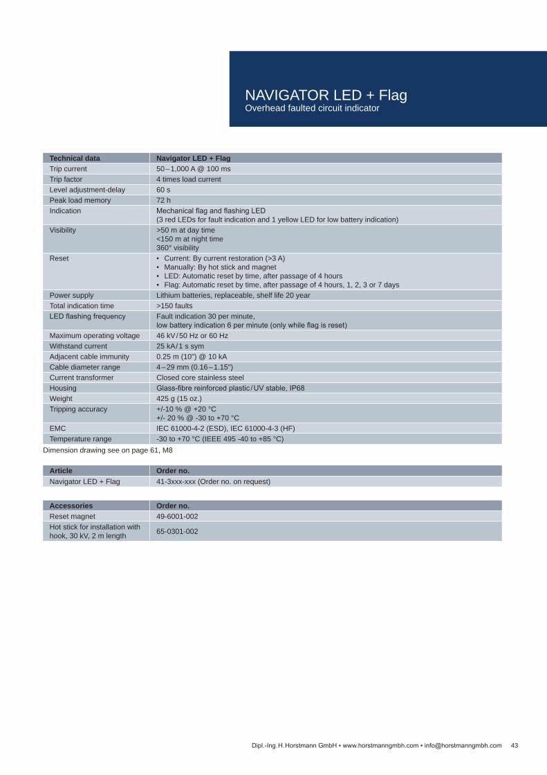
Technical data Navigator LED + FlagTrip current 50 – 1,000 A @ 100 ms Trip factor 4 times load currentLevel adjustment-delay 60 sPeak load memory 72 hIndication Mechanical flag and flashing LED
(3 red LEDs for fault indication and 1 yellow LED for low battery indication)Visibility >50 m at day time
<150 m at night time360° visibility
Reset Current: By current restoration (>3 A) Manually: By hot stick and magnet LED: Automatic reset by time, after passage of 4 hours Flag: Automatic reset by time, after passage of 4 hours, 1, 2, 3 or 7 days
Power supply Lithium batteries, replaceable, shelf life 20 yearTotal indication time >150 faultsLED flashing frequency Fault indication 30 per minute,
low battery indication 6 per minute (only while flag is reset)Maximum operating voltage 46 kV / 50 Hz or 60 HzWithstand current 25 kA / 1 s symAdjacent cable immunity 0.25 m (10") @ 10 kACable diameter range 4 – 29 mm (0.16 – 1.15")Current transformer Closed core stainless steelHousing Glass-fibre reinforced plastic / UV stable, IP68Weight 425 g (15 oz.)Tripping accuracy +/-10 % @ +20 °C
+/- 20 % @ -30 to +70 °CEMC IEC 61000-4-2 (ESD), IEC 61000-4-3 (HF)Temperature range -30 to +70 °C (IEEE 495 -40 to +85 °C)
Article Order no.Navigator LED + Flag 41-3xxx-xxx (Order no. on request)
Accessories Order no.Reset magnet 49-6001-002Hot stick for installation with hook, 30 kV, 2 m length 65-0301-002
43Dipl.-Ing. H. Horstmann GmbH www.horstmanngmbh.com [email protected]
Dimension drawing see on page 61, M8
NAVIGATOR LED + FlagOverhead faulted circuit indicator
44 Dipl.-Ing. H. Horstmann GmbH www.horstmanngmbh.com [email protected]
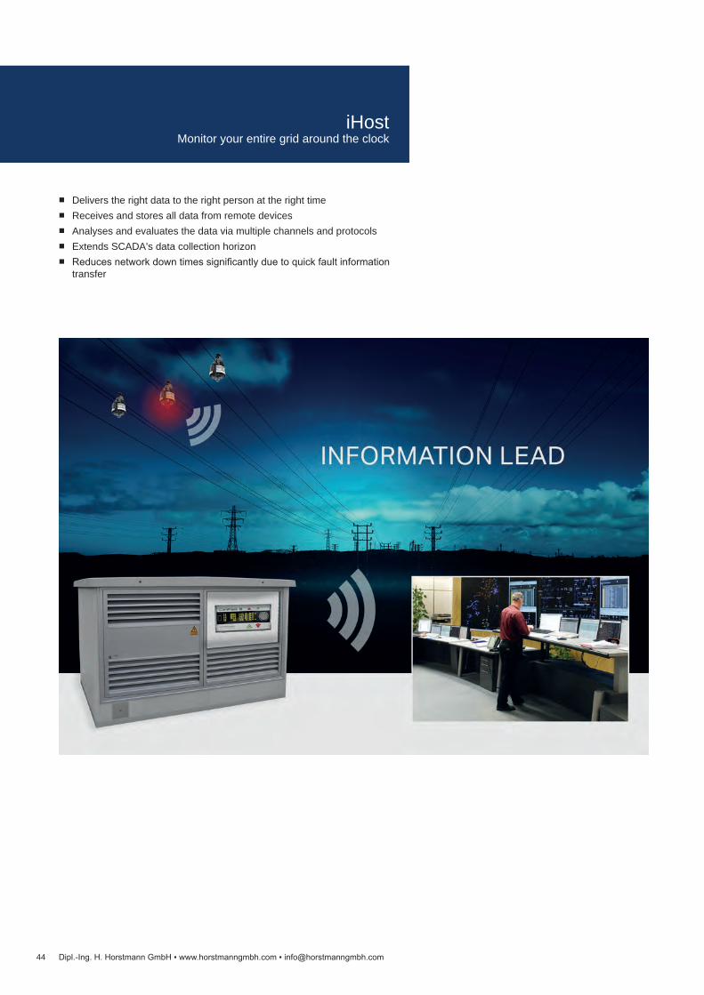
Delivers the right data to the right person at the right time Receives and stores all data from remote devices Analyses and evaluates the data via multiple channels and protocols Extends SCADA's data collection horizon Reduces network down times significantly due to quick fault information
transfer
iHostMonitor your entire grid around the clock

45Dipl.-Ing. H. Horstmann GmbH www.horstmanngmbh.com [email protected]
iHost – link between short-circuit and earth fault indicators and SCADAiHost provides a single platform to efficiently manage the increasing number of remote devices installed throughout the power network.
Installing iHost enables you to make best use of these smart devices whilst at the same time extending the information horizon of existing SCADA.
Data concentrator for short-circuit and earth fault indicators Bundles and processes all data received from remote field devices Provides data access at any time in various ways and devices
Central management of all field devices – with one click Grid monitoring: system overview, data analysis, health checks Configuration and firmware updates from SCADA
Data on demand Customised visualisation of data and alarms Individual notifications, generated automatically
Embedded database Grid data available from day one of installation Flexible data provision for asset management, planning, foremen and
further user
iHostMonitor your entire grid around the clock

46 Dipl.-Ing. H. Horstmann GmbH www.horstmanngmbh.com [email protected]
Remote monitoring solutions for distribution utilitiesOne iHost solution fits your requirements:
iHost Cloud iHost Compact iHost Solo / iHost Pro
The options differ in the way of data provision for the different departments of the distribution utility.
iHost CloudFor smaller scale projects or pilot schemes iHost Cloud is the best choice. Quick and easy implementation works without software installation. Handling is very user-friendly – all you need is a web-enabled device, your username and pass-word. Customised notifications in case of a fault or alarms are possible via SMS and e-mail.
iHost CompactIf you want to see the data in your SCADA iHost Compact is the right choice. With this solution iHost is part of your SCADA infrastructure. Installed on your own server or a virtual server iHost is a gateway that processes all data and for-wards them directly to your SCADA. With iHost Compact you manage all remote devices installed in the power network.
iHost Solo / iHost ProWith iHost Solo and iHost Pro all measured values as well as fault information are transferred directly to SCADA and are available on mobile devices at the same time. All data are stored in iHost. Installed in your premises these solu-tions provide you multiple options regarding the use, analysis and visualisation of data.
iHost Solo is designed for medium sized distribution networks whereas iHost Pro can handle the variety of remote devices of large distribution utilities.
Complete with high availability resilience the system supports all departments of your company. The system can be tailored for user groups depending on their requirements.
iHost Cloud
iHost Compact
iHost Solo / Pro
iHostMonitor your entire grid around the clock

Feature iHost Cloud iHost Compact iHost Solo iHost ProHardware (HW) Cloud service / data
centreSever / virtual server running MS Windows Server OS
HW / Server arrangement High availability Software as a service
Single server (customer or Horstmann supplied)
Virtual appliance recommended
Single server, customer or Horstmann supplied
Virtual appliance recommended
Multiple server, cus-tomer or Horstmann supplied
Virtual appliance recommended
Visualisation Web browser SCADA Web browser and SCADASIM cards for smart FCI / RTU
Included in service Customer supplied SIM with private APN
iHost licence type Software as a service Perpetual Licence feeRTU count 1 – 1000 50 / 250 / 500 100 / 500 / 1000 1000 / 2000 / 5000Limits of users / user roles 50 / 3 2 / 2 50 / 10 unlimited / 50Maps option Maps included No Yes (option)Notifications Yes (e-mail / SMS) No Yes (e-mail / SMS)Historian Yes No YesData access API No No YesSCADA protocols n/a DNP3 TCP-IP / serial (or IEC60870-5-101 or IEC60870-5-104)Simultaneous SCADA channels
n/a 2 10
iHost Cloud iHost Compact iHost Solo iHost ProEquipment set Cloud 1 – 1000 Compact 50 Solo 100 Pro 1000Order No. 79-1010-000 79-1110-000 79-1210-000 79-1310-000
Equipment set Cloud – 1 SIM-S* Compact 250 Solo 500 Pro 2000Order No. 79-1040-000 79-1120-000 79-1220-000 79-1320-000
Equipment set Cloud – 1 SIM-M* Compact 500 Solo 1000 Pro 5000Order No. 79-1041-000 79-1130-000 79-1230-000 79-1330-000
iHost Cloud iHost Compact iHost Solo iHost ProSW installation and commissioning
not necessary Installation package (remote VPN access)
Basic installation kit (remote VPN access)
Advanced installation kit (remote VPN access)
Order No. – 79-1160-000 79-1260-000 79-1360-000
Technical support for 12 month
not necessary iHost Compact Technical support
iHost Solo Technical suport
iHost Pro Technical support
Order No. – 79-1150-000 79-1250-000 79-1350-000
47Dipl.-Ing. H. Horstmann GmbH www.horstmanngmbh.com [email protected]
* SIM-S includes a maximum of 10 MB data volume per SIM card* SIM-M includes >10 MB data volume per SIM card
iHostMonitor your entire grid around the clock
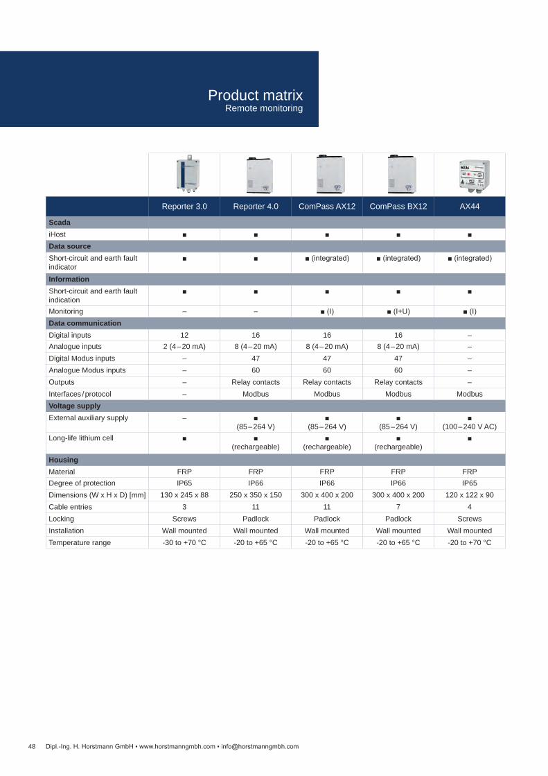
Reporter 3.0 Reporter 4.0 ComPass AX12 ComPass BX12 AX44
ScadaiHost Data sourceShort-circuit and earth fault indicator
(integrated) (integrated) (integrated)
InformationShort-circuit and earth fault indication
Monitoring – – (I) (I+U) (I)Data communicationDigital inputs 12 16 16 16 –Analogue inputs 2 (4 – 20 mA) 8 (4 – 20 mA) 8 (4 – 20 mA) 8 (4 – 20 mA) –Digital Modus inputs – 47 47 47 –Analogue Modus inputs – 60 60 60 –Outputs – Relay contacts Relay contacts Relay contacts –Interfaces / protocol – Modbus Modbus Modbus ModbusVoltage supplyExternal auxiliary supply –
(85 – 264 V)
(85 – 264 V)
(85 – 264 V)
(100 – 240 V AC)Long-life lithium cell
(rechargeable)
(rechargeable)
(rechargeable)
HousingMaterial FRP FRP FRP FRP FRPDegree of protection IP65 IP66 IP66 IP66 IP65Dimensions (W x H x D) [mm] 130 x 245 x 88 250 x 350 x 150 300 x 400 x 200 300 x 400 x 200 120 x 122 x 90Cable entries 3 11 11 7 4Locking Screws Padlock Padlock Padlock ScrewsInstallation Wall mounted Wall mounted Wall mounted Wall mounted Wall mountedTemperature range -30 to +70 °C -20 to +65 °C -20 to +65 °C -20 to +65 °C -20 to +70 °C
48 Dipl.-Ing. H. Horstmann GmbH www.horstmanngmbh.com [email protected]
Product matrix Remote monitoring
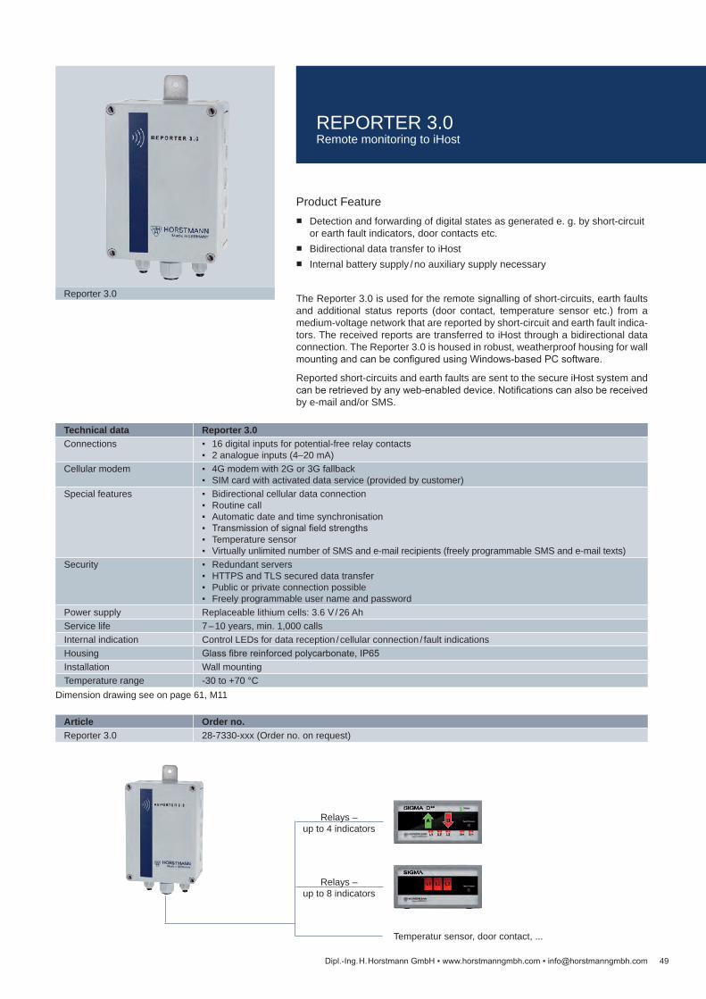
Article Order no.Reporter 3.0 28-7330-xxx (Order no. on request)
Technical data Reporter 3.0Connections 16 digital inputs for potential-free relay contacts
2 analogue inputs (4–20 mA)Cellular modem 4G modem with 2G or 3G fallback
SIM card with activated data service (provided by customer)Special features Bidirectional cellular data connection
Routine call Automatic date and time synchronisation Transmission of signal field strengths Temperature sensor Virtually unlimited number of SMS and e-mail recipients (freely programmable SMS and e-mail texts)
Security Redundant servers HTTPS and TLS secured data transfer Public or private connection possible Freely programmable user name and password
Power supply Replaceable lithium cells: 3.6 V / 26 AhService life 7 – 10 years, min. 1,000 callsInternal indication Control LEDs for data reception / cellular connection / fault indicationsHousing Glass fibre reinforced polycarbonate, IP65Installation Wall mountingTemperature range -30 to +70 °C
49
Reporter 3.0
Dipl.-Ing. H. Horstmann GmbH www.horstmanngmbh.com [email protected]
Dimension drawing see on page 61, M11
Product Feature Detection and forwarding of digital states as generated e. g. by short-circuit
or earth fault indicators, door contacts etc. Bidirectional data transfer to iHost Internal battery supply / no auxiliary supply necessary
The Reporter 3.0 is used for the remote signalling of short-circuits, earth faults and additional status reports (door contact, temperature sensor etc.) from a medium-voltage network that are reported by short-circuit and earth fault indica-tors. The received reports are transferred to iHost through a bidirectional data connection. The Reporter 3.0 is housed in robust, weatherproof housing for wall mounting and can be configured using Windows-based PC software.
Reported short-circuits and earth faults are sent to the secure iHost system and can be retrieved by any web-enabled device. Notifications can also be received by e-mail and/or SMS.
Temperatur sensor, door contact, ...
Relays – up to 4 indicators
Relays – up to 8 indicators
REPORTER 3.0Remote monitoring to iHost

50
Reporter 4.0
Dipl.-Ing. H. Horstmann GmbH www.horstmanngmbh.com [email protected]
Product features Detection and forwarding of digital states as generated e. g. by short-circuit
or earth fault indicators Transfer via bidirectional data connection to iHost Auxiliary supply necessary
The Reporter 4.0 is used for the remote signalling of short-circuits, earth faults and additional status reports from a medium-voltage network. The information is transferred by ComPass B or ComPass B 2.0 in particular. Voltage, current, load flow direction, power factor, power, energy and frequency are also meas-ured and monitored. The received reports are transferred to iHost through a bidirectional data connection. The Reporter 4.0 is housed in robust, weather-proof housing for wall mounting and can be configured using Windows-based PC software. It is also possible to connect other short-circuit and earth fault indicators.
Reported short-circuits, earth faults and measuring values are sent to the se-cure iHost system and can be retrieved by any web-enabled device (with login and password). Notifications can also be received by e-mail and/or SMS..
External auxiliary supply
Modbus – up to 4 indicators
Temperatur sensor, door contact, ...
Modbus – up to 4 indicators
Relays – up to 4 indicators
Relays – up to 8 indicators
REPORTER 4.0Remote monitoring to iHost
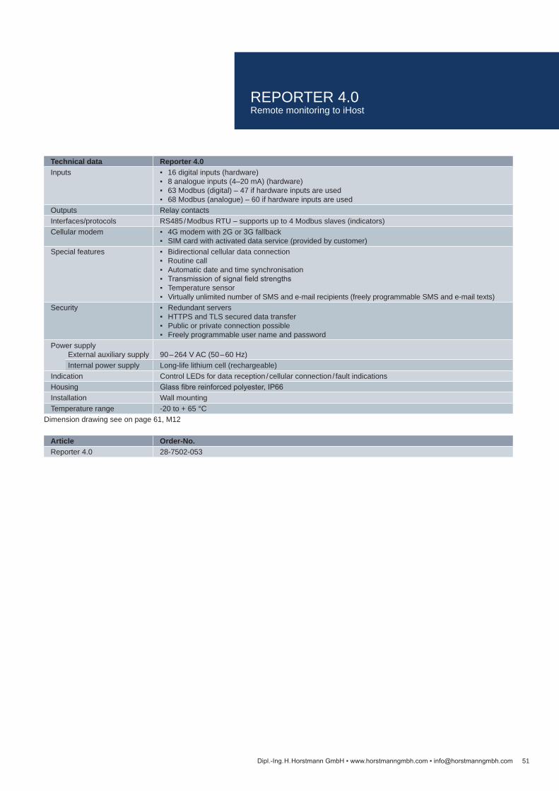
Technical data Reporter 4.0Inputs 16 digital inputs (hardware)
8 analogue inputs (4–20 mA) (hardware) 63 Modbus (digital) – 47 if hardware inputs are used 68 Modbus (analogue) – 60 if hardware inputs are used
Outputs Relay contactsInterfaces/protocols RS485 / Modbus RTU – supports up to 4 Modbus slaves (indicators)Cellular modem 4G modem with 2G or 3G fallback
SIM card with activated data service (provided by customer)Special features Bidirectional cellular data connection
Routine call Automatic date and time synchronisation Transmission of signal field strengths Temperature sensor Virtually unlimited number of SMS and e-mail recipients (freely programmable SMS and e-mail texts)
Security Redundant servers HTTPS and TLS secured data transfer Public or private connection possible Freely programmable user name and password
Power supplyExternal auxiliary supply 90 – 264 V AC (50 – 60 Hz)Internal power supply Long-life lithium cell (rechargeable)
Indication Control LEDs for data reception / cellular connection / fault indicationsHousing Glass fibre reinforced polyester, IP66Installation Wall mountingTemperature range -20 to + 65 °C
Article Order-No.Reporter 4.0 28-7502-053
51Dipl.-Ing. H. Horstmann GmbH www.horstmanngmbh.com [email protected]
Dimension drawing see on page 61, M12
REPORTER 4.0Remote monitoring to iHost

52
AX44
Dipl.-Ing. H. Horstmann GmbH www.horstmanngmbh.com [email protected]
Product features Earth fault and short-circuit indicator (for medium voltage networks) Phase-selective current monitoring Transfer via bidirectional data connection to iHost Auxiliary supply necessary
The AX44 is a compact underground cable faulted circuit indicator with inte-grated RTU, assisting utilities to detect earth faults and short-circuits in medium voltage networks. Its additional feature to monitor the phase selective load flow currents with high accuracy combines important grid parameters with network disturbance information to improve efficiency and reducing costs by unifying them into one single device.
All monitored values, as well as faults, alarms or warnings will be reported im-mediately with date/time stamp to Scada. Horstmann´s intuitive and user friend-ly iHost application provides network overview anytime – not only in case of outages.
Distribution utilities are able to analyse and evaluate a variety of information, leading to better understanding and management of complex networks. Fur-thermore, energy suppliers will be able to be more proactive in preventing inci-dents and get informed of faults by SMS and e-mail notifications.
It supports distribution systems to increase reliability, uptime and shorten fault finding to reduce outage times.
or
AX44Remote monitoring to iHost

Article Order no.AX44 (without CTs) 28-7504-010
Technical data AX44I>> Short-circuit trip current 25 – 500 AtI>> Response delay 40 – 1,000 msIE> Earth fault trip current 25 – 500 AtIE> Response delay 40 – 1,000 msMeasured values Phase currents L1, L2, L3Reset Manual reset
Automatic time reset (user adjustable) Automatic after current restoration Automatic after low voltage restoration (power supply)
Event history Unlimited on web-hosted application (iHost)Communication SIM card with activated data service (provided by customer)Monitoring Single-phase current measurements, phase angles, averages and maximas
Temperature GSM signal strength, Communication status
Web-application features Mimic for fast and easy overview of necessary data GIS (Geographic information system) GPS data of installed AX41 Display of warnings and alarms E-mail and SMS notification manager Setting of customizable thresholds on analogue data Interactive trend graphs (exportable) Unlimited data retention
Security Redundant servers HTTPS- and TLS secured data transmission Public or private connection possible Freely programmable user name and password
Power supply 110 – 250 V AC or 12 – 24 V DCHousing Glass fibre reinforced polycarbonate, IP65Temperature range -20 to +70 °C
53Dipl.-Ing. H. Horstmann GmbH www.horstmanngmbh.com [email protected]
Dimension drawing see on page 62, M13
AX44Remote monitoring to iHost
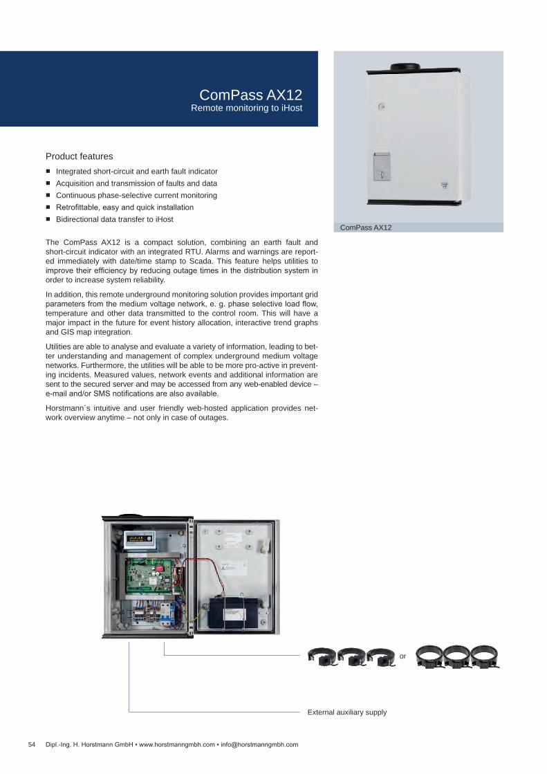
54
ComPass AX12
Dipl.-Ing. H. Horstmann GmbH www.horstmanngmbh.com [email protected]
Product features Integrated short-circuit and earth fault indicator Acquisition and transmission of faults and data Continuous phase-selective current monitoring Retrofittable, easy and quick installation Bidirectional data transfer to iHost
The ComPass AX12 is a compact solution, combining an earth fault and short-circuit indicator with an integrated RTU. Alarms and warnings are report-ed immediately with date/time stamp to Scada. This feature helps utilities to improve their efficiency by reducing outage times in the distribution system in order to increase system reliability.
In addition, this remote underground monitoring solution provides important grid parameters from the medium voltage network, e. g. phase selective load flow, temperature and other data transmitted to the control room. This will have a major impact in the future for event history allocation, interactive trend graphs and GIS map integration.
Utilities are able to analyse and evaluate a variety of information, leading to bet-ter understanding and management of complex underground medium voltage networks. Furthermore, the utilities will be able to be more pro-active in prevent-ing incidents. Measured values, network events and additional information are sent to the secured server and may be accessed from any web-enabled device – e-mail and/or SMS notifications are also available.
Horstmann´s intuitive and user friendly web-hosted application provides net-work overview anytime – not only in case of outages.
or
External auxiliary supply
ComPass AX12Remote monitoring to iHost
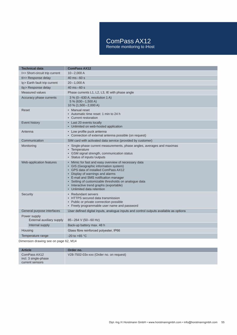
Article Order no.ComPass AX12incl. 3 single-phase current sensors
V28-7502-03x-xxx (Order no. on request)
Technical data ComPass AX12I>> Short-circuit trip current 10 – 2,000 AtI>> Response delay 40 ms – 60 sIE> Earth fault trip current 20 – 1,000 AtIE> Response delay 40 ms – 60 sMeasured values Phase currents L1, L2, L3, IE with phase angleAccuracy phase currents 3 % (0 – 630 A, resolution 1 A)
5 % (630 – 1,500 A)10 % (1,500 – 2,000 A)
Reset Manual reset Automatic time reset: 1 min to 24 h Current restoration
Event history Last 20 events locally Unlimited on web-hosted application
Antenna Low profile puck antenna Connection of external antenna possible (on request)
Communication SIM card with activated data service (provided by customer)Monitoring Single-phase current measurements, phase angles, averages and maximas
Temperature GSM signal strength, communication status Status of inputs / outputs
Web-application features Mimic for fast and easy overview of necessary data GIS (Geographic information system) GPS data of installed ComPass AX12 Display of warnings and alarms E-mail and SMS notification manager Setting of customizable thresholds on analogue data Interactive trend graphs (exportable) Unlimited data retention
Security Redundant servers HTTPS secured data transmission Public or private connection possible Freely programmable user name and password
General purpose interfaces User defined digital inputs, analogue inputs and control outputs available as optionsPower supply
External auxiliary supply 85 – 264 V (50 – 60 Hz)Internal supply Back-up battery max. 48 h
Housing Glass fibre reinforced polyester, IP66Temperature range -20 to +65 °C
55Dipl.-Ing. H. Horstmann GmbH www.horstmanngmbh.com [email protected]
Dimension drawing see on page 62, M14
ComPass AX12Remote monitoring to iHost

56
ComPass BX12
Dipl.-Ing. H. Horstmann GmbH www.horstmanngmbh.com [email protected]
Product features Integrated directional short-circuit and directional earth fault indicator Acquisition and transmission of faults and data Continuous phase-selective load monitoring and load flow direction monitor-
ing, P, Q, S, cos φ, E Retrofittable, easy and quick installation Bidirectional data transfer to iHost
The ComPass BX12 is a compact solution, combining a directional earth fault and directional short-circuit indicator with an integrated RTU.
The voltage is measured by an integrated voltage detecting system, either the Wega 1.2 C, Wega 2.2 C or Wega 1.2 C vario. Voltage tapping is also possible via HR interfaces or on divider insulators with capacitive coupling (set of meas-uring lines).
Alarms and warnings are reported immediately with date/time stamp to Scada. This feature helps utilities to improve their efficiency by reducing outage times in the distribution system in order to increase system reliability.
In addition, this remote underground monitoring solution provides important grid parameters from the medium voltage network, e. g. phase selective current load flow, transmitted to the control room. This will have a major impact in the future for event history allocation, interactive trend graphs and GIS map integration.
Utilities are able to analyse and evaluate a variety of information, leading to bet-ter understanding and management of complex underground medium voltage networks.
Furthermore the utilities will be able to be more pro-active in preventing inci-dents.
Measured values, events and additional information are sent to the secure web-hosted server and may be accessed from any web-enabled device – e-mail and/or SMS notifications are also available.
Horstmann´s intuitive and user friendly web-hosted application provides net-work overview anytime – not only in case of outages.
External auxiliary supply
or
Capacitive voltage signal
ComPass BX12Remote monitoring to iHost

Article Order no.ComPass BX12incl. 3 single-phase current sensors
V28-7502-05x-xxx (Order no. on request)
Technical data ComPass BX12I>> Short-circuit trip current 50 – 2,000 AtI>> Response delay 40 ms – 60 sIE> Earth fault trip current 20 – 1,000 A (low-impedance/solidly earthed network)
5 – 200 A (isolated/compensated network)tIE> Response delay 40 ms – 60 sV> Overvoltage trip current 100 – 200 %V< Undervoltage trip current 0 – 100 %Measured values Phase currents I1, I2, I3, IE with phase angle
Phase-to-earth voltage V1, V2, V3, Vnom and phase-to-phase voltage V12, V23, V31, Vnom Load flow direction B↓ or A↑ Power P, Q, S and cos φ (P 1,2,3, Q 1,2,3, S 1,2,3, cos φ 1,2,3 via RS485) Effective energy (E1A, E2A, E3A, EA, E1B, E2B, E3B, EB) Operating current, I1,2,3 ø15 min, I max. 24 h / 7 days / 365 days, demand indicator Imax. LR Frequency f
Accuracy phase currents 3 % (0 – 630 A, resolution 1 A) 5 % (630 – 1,500 A)10 % (1,500 – 2,000 A)
Reset Manual reset Automatic time reset: 1 min to 24 h Auxiliary supply restoration Voltage and current restoration
Event history Last 20 events locally Unlimited on web-hosted application
Antenna Low profile puck antenna Connection of external antenna possible (on request)
Communication SIM card with activated data service (provided by customer)Monitoring Single-phase current measurements, phase angles, averages and maximas
Temperature GSM signal strength, communication status Status of inputs / outputs
Web-application features Mimic for fast and easy overview of necessary data GIS (Geographic information system) GPS data of installed ComPass BX12 Display of warnings and alarms E-mail and SMS notification manager Setting of customizable thresholds on analogue data Interactive trend graphs (exportable) Unlimited data retention
Security HTTPS secured data transmission Freely programmable user name and password Public or private connection possible Monitoring of signal strength and communication status
General purpose interfaces User defined digital inputs, analogue inputs and control outputs available as optionsVoltage detecting system Integrated VDS:
Phase selective detection of voltage absent / presence Design according to IEC 61243-5 (VDE 0682-415) Self-maintenance test, maintenance-free, integrated display test Energy provided by the measuring signal
Power supplyExternal auxiliary supply 85 – 264 V (50 – 60 Hz)Internal power supply Back-up battery max. 48 h
Housing Glass fibre reinforced polyester, IP66Temperature range -20 to +65 °C
57Dipl.-Ing. H. Horstmann GmbH www.horstmanngmbh.com [email protected]
Dimension drawing see on page 62, M15
ComPass BX12Remote monitoring to iHost

58
SMART REPORTER C1
Dipl.-Ing. H. Horstmann GmbH www.horstmanngmbh.com [email protected]
Product features Controls up to 12 Smart Navigator FCI's Bidirectional data transfer to iHost Remote and local configuration Rechargeable backup battery Includes Smart PMU for intelligent power management Tamper detection
Provided information: Overhead line fault indication (permanent / momentary) Overhead line de-energization (loss of current alarms) Average load current and actual load current Peak load current (min and max) Counters: permanent faults / momentary faults Device temperature, conductor temperature (option) Routine call and health check Battery status
The Smart Reporter C1 is a robust, pole mounted solution that interacts with the Horstmann Smart Navigator overhead FCI's. It provides information about events and fault locations for distribution and sub-transmission overhead lines. It provides information such as monitoring, fault indication, event history and fault locations for distribution and sub-transmission overhead lines.
The Smart Reporter C1 acts as an access point that relays information from the Smart Navigators.
Horstmann´s intuitive and user friendly web-hosted application iHost provides network overview anytime – not only in case of outages. This solution helps utilities to improve their efficiency by reducing outage times in the distribution system and increase system reliability.
SMART REPORTER C1Remote monitoring to iHost

Technical data Smart Reporter C1Features Door contact switch for tamper detection
Internal LEDs to support installation and commissioning Optional internal heater for operation under extreme climate conditions
FCI connection Short Range Radio Link Controller for up to 12 Navigator FCI’s (2.4 GHz)Range FCI ↔ Smart Reporter C1 30 m (line-of-sight)Power supply1) 85 – 264 V±10 %, max. current at 220 V AC = 1 A (<1 min), 50 mA (continuous)Back-up battery Rechargeable
Lifetime 8 – 10 years at +20 °C (>7 days with power saving mode)Antenna GSM/GPRS low profile puck antenna
2.4 GHz low profile puck antenna Connection of external antenna possible (on request)
Communication SIM card with activated data service (provided by customer)Web-application features Mimic for fast and easy overview of necessary data
GIS (Geographic Information System) GPS data of installed Smart Reporter C1 Display of warnings and alarms E-mail and SMS notification manager Unlimited data retention Surveillance of signal strength, communication status and battery health status
Event history Unlimited on web-hosted applicationSecurity Redundant servers
HTTPS and TLS secured data transfer Public or private connection possible Freely programmable user name and password
EMC IEC 61000-4, IEC 61000-6Housing Fully insulated, glass fibre reinforced polyesterDegree of protection IP66 / NEMA 4XTemperature range -20 to +65 °C
Article Order no.Smart Reporter C1 AC 28-3131-01x (Order no. on request)Smart Reporter C1 Solar 28-3130-012Smart Navigator 43-x0x6-100 (Order no. on request)
59Dipl.-Ing. H. Horstmann GmbH www.horstmanngmbh.com [email protected]
1) for AC solution2) for solar solution
Dimension drawing see on page 61, M10
SMART REPORTER C1Remote monitoring to iHost

60
40
40
19
M1: Rotor Indicator
34
67
19
M2: Fluid Indicator
48
96
78 85
96
M3: ALPHA E, ComPass, OPTO, SIGMA
48
96
78 96
111
M4: ComPass A 2.0 / B 2.0 / BS 2.0
48
96
78 96 107
M5: ALPHA M
48
96
78
45
85
M6: EARTH
Dipl.-Ing. H. Horstmann GmbH www.horstmanngmbh.com [email protected]
Dimension DrawingsShort-circuit and earth fault indicators

61
95
25
155
M8: NAVIGATOR
300
400
4
33
460
229
M9: SMART REPORTER
139
101 1
65
46
M7: EARTH, OPTO, SIGMA plus 4
66
400
433
300 229
M10: SMART REPORTER C1
130 136
180
210
215
88
M11: REPORTER 3.0
180 250
350
410
383
M12: REPORTER 4.0
Dipl.-Ing. H. Horstmann GmbH www.horstmanngmbh.com [email protected]
Dimension DrawingsShort-circuit and earth fault indicators

62
120
122
150
127 90
M13: AX41
300
400
4
33
458
229
M14: ComPass AX12
300
400
4
33
461
229
M15: ComPass BX12
Dipl.-Ing. H. Horstmann GmbH www.horstmanngmbh.com [email protected]
Dimension DrawingsShort-circuit and earth fault indicators

63Dipl.-Ing. H. Horstmann GmbH www.horstmanngmbh.com [email protected]
Voltage detectors and voltage detecting systems are used to verify the presence (“Voltage Present”) and absence (“Voltage Not Present”) condition of voltage in medium voltage switchgears, electrical equipment, railway overhead contact wires or of work places when working under voltage.
The absence of voltage on disconnected switchgear parts can be verified by:
voltage detector types: FL-I, TP-I, BO-A 2.0 or Comet BL-I/BL-A/BK-I/BK-A/BS-I/BS-A or
pluggable, capacitive voltage detecting systems types HR-ST, LRM-ST or Orion or
fixed installed capacitive voltage detecting systems: Wega models
Voltage Detectors and Phase Comparatorsmust only be used at their permitted nominal voltages (phase-phase voltage) and nominal frequency. The corresponding data can be found on the type plate. Voltage detectors for nominal voltage ranges or switchable voltage detectors (e. g. BS-I/BS-A) can be used for systems with different voltage ratings.
According to the IEC 61243-1 (VDE 0682-411) standard it must be ensured that the display of the FL-I and TP-I type voltage detectors (without self-test facility) must be verified on a live conductor before and after each use.
The BL-I/BL-A, BK-I/BK-A and BS-I/BS-A voltage detectors are provided with a built-in self-test facility which verifies the display, the evaluation unit and the test probe tip directly after the device has been switched on. Due to this feature it is not strictly necessary to submit the voltage detector to live testing. However, it is recommended to carry out this test if a live conductor is available.
BO-A 2.0 is a voltage detector for medium voltage railway overhead contact wires. It is especially developed for 16.7 Hz networks and voltage detection from the ground. BO-A 2.0 has a built-in self-test facility and signals if the volt-age detector is used in a network with a deviating frequency.
Voltage testers and phase comparators are subject to maintenance tests (See on page 92).
Capacitive Voltage Detecting Systems (VDS)Voltage Detecting Systems (VDS) are divided into two groups:
pluggable systems, to which a portable voltage indicator (e. g. HR-ST) can be connected via an interface with a permanently installed coupling part (e. g. HR-interface). Both the indicator and the coupling part are subject to maintenance tests (see on page 92).
integrated systems (Wega) which are incorporated in the electrical equip-ment constituting an integral part of such equipment. Integrated VDS (Wega) are additionally provided with either an LRM interface or a measur-ing point for phase comparison. The integral permanently working current flow monitoring and indication makes a maintenance test superfluous.
The Orion 3.1 / M.1 device is a combined indicator for voltage detection, phase comparison and coupling part testing on HR and LRM interfaces.
Voltage Detectors and Voltage Detecting SystemsGeneral information
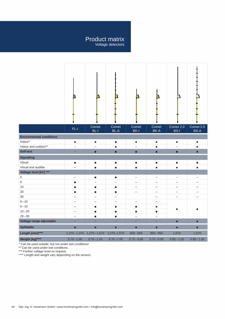
64 Dipl.-Ing. H. Horstmann GmbH www.horstmanngmbh.com [email protected]
FL-I Comet
BL-ICometBL-A
CometBK-I
CometBK-A
Comet 2.0BS-I
Comet 2.0BS-A
Environmental conditionsIndoor* Indoor and outdoor** – – – – Self-test –
SignallingVisual Visual and audible – Voltage level [kV] ***5 – – – – –6 – – – – – –10 – – – –20 – – – –30 – – – – – –5 – 10 – – – – –
6 – 10 – 10 – 20 – 20 – 30 – – –Voltage range adjustable – – – – –
Splittable
Length [mm]**** 1,270 – 1,370 1,270 – 1,570 1,270–1,570 900 – 955 900 – 955 1,570 1,570
Weight [kg]**** 0.70 – 1.00 0.70 – 1.00 0.70 – 1.00 0.75 – 0.85 0.75 – 0.85 0.85 – 1.00 0.85 – 1.00* Can be used outside, but not under wet conditions!** Can be used under wet conditions.*** Further voltage level on request.**** Length and weight vary depending on the version.
Product matrixVoltage detectors

65Dipl.-Ing. H. Horstmann GmbH www.horstmanngmbh.com [email protected]
TP-I Compare 2.0 PGII
Environmental conditionsIndoor* Indoor and outdoor** – –Self-test – –
SignallingVisual Visual and audible – – –Voltage level [kV] ***5 – – 6 – – 10 – – 20 – – 30 – – 33 – –6 – 10 – –10 – 20 –20 – 36 –Voltage range adjustable – – –
Splittable
Length [mm]**** 895 1,420 1,220 – 1,420
Weight [kg]**** 0.70 0.95 1.60* Can be used outside, but not under wet conditions!** Can be used under wet conditions.*** Further voltage level on request.**** Length and weight vary depending on the version.
Product matrixVoltage detectors and phase comparators

Technical data FL-IUse In dry conditions, normally indoorsIndication 3 red LEDsNominal frequency 50 Hz (optional 60 Hz)Operating temperature -25 to +70 °C, climatic class N and W
Nominal voltage [kV] Total length a [mm] Insertion depth b [mm] Order no. 6 1,270 463 50-1201-00110 1,270 463 50-1201-00220 1,370 563 50-1201-003
Accessories Order no.Extension rod See on page 82Probe tipUniversal plastic case
66
FL-I with indication unit
a
b
Dipl.-Ing. H. Horstmann GmbH www.horstmanngmbh.com [email protected]
Product features Designed according to IEC 61243-1 (VDE 0682-411), Category S Indoor type Visual voltage indication No battery
The FL-I device is a voltage detector for testing the voltage on one pole. This device is designed to detect operating voltages clearly indicating either the “voltage present“ or “voltage not present“ state. This device does not have a built-in power source (battery) and thus no self-test function.
For transportation purposes, the insulating element can be removed from the display unit with the contact electrode.
According to the German accident prevention standard DGUV Regulation 3 (Table 1c),the device is subject to maintenance tests with minimum intervals of at least 6 years.
FL-IVoltage detector without self-test

Technical data TP-IUse In dry conditions, normally indoorsIndication 3 red LEDsNominal frequency 50 HzOperating temperature -25 to +70 °C, climatic class N and W
Nominal voltage [kV] Total length a [mm] Insertion depth b [mm] Order no.33 895 112 51-0201-0046 – 10 895 112 51-0201-00510 – 20 895 112 51-0201-00320 – 36 895 112 51-0201-007
Accessories Order no.Function tester 52-0111-001Probe tip See on page 82Universal plastic case
67
TP-I with indication unit
a
b
Dipl.-Ing. H. Horstmann GmbH www.horstmanngmbh.com [email protected]
Product features Designed according to IEC 61243-1 (VDE 0682-411), Category S Indoor type Visual voltage indication No battery
The TP-I device is a two pole tester for capacitive test points on connectors in medium voltage switchgears. This device determines the operating conditions of high voltage installations according to EN 50110-1 (DIN VDE 0105 Part 1 and 100). This device does not have a built-in power source (battery) and thus no self-test function.
For transportation purposes, the insulating element can be removed from the display unit with the contact electrode.
According to the German accident prevention standard DGUV Regulation 3 (Table 1c),the device is subject to maintenance tests with minimum intervals of at least 6 years.
TP-IVoltage detector for capacitive test points

68
BL-I / BL-A with indication unit
a
b
Dipl.-Ing. H. Horstmann GmbH www.horstmanngmbh.com [email protected]
Product features Designed according to IEC 61243-1 (VDE 0682-411), Category S BL-I: indoor type BL-A: outdoor type Voltage indication visual
or visual/audible Built-in self-test function
The Comet BL-I/BL-A devices are capacitive voltage detectors for testing the voltage on one pole. They are intended for the detection of operating voltages clearly indicating either the “voltage present” or “voltage not present” state.
The voltage detectors are provided with a built-in self-test facility which checks the function of the circuit including the contact electrode (comprehensive self-test function) before each use.
For transportation purposes, the insulating element can be removed from the display with the contact electrode.
According to the German accident prevention standard DGUV Regulation 3 (Table 1c), the device is subject to maintenance tests with minimum intervals of at least 6 years.
Comet BL-I / Comet BL-AVoltage detectors with self-test

Technical data Comet BL-I Comet BL-AUse In dry conditions,
normally indoorsIn dry and wet conditions, either indoors or outdoors
Indication Visual: 1 red LED / 1 green LED Visual and audible: 1 red LED / 1 green LED / 1 signal transmitter
Nominal frequency 50 Hz (optional 60 Hz)Power supply 2 lithium cells, each 1.5 Ah, 2 x 3 V,
Battery service life: 6 years based on 10 ready cycles per day for a total of 230 work days per yearOperating temperature -25 to +70 °C, climatic class N and W
Nom
inal
vol
tage
[kV]
Tota
l len
gth
a [m
m]
Inse
rtio
n de
pth
b [m
m]
Order no.
Comet BL-I Comet BL-A
5 1,270 462 50-0901-011 50-0903-008 50-1001-009 50-1003-00910 1,270 462 50-0901-012 50-0903-009 50-1001-010 50-1003-01020 1,420 612 50-0901-013 50-0903-010 50-1001-011 50-1003-011
6 – 10 1,420 612 50-0901-014 50-0903-011 50-1001-012 50-1003-01210 – 20 1,570 762 50-0901-015 50-0903-012 50-1001-013 50-1003-01320 – 30 1,570 762 50-0901-022 50-0903-018 50-1001-015 50-1003-018
Accessories Order no.Extension rod See on page 82Probe tipExtension with contact electrodeDouble prong adapterUniversal plastic case
69Dipl.-Ing. H. Horstmann GmbH www.horstmanngmbh.com [email protected]
Comet BL-I / Comet BL-AVoltage detectors with self-test

70
BK-I / BK-A with indication unit
a
b
Dipl.-Ing. H. Horstmann GmbH www.horstmanngmbh.com [email protected]
Product features Designed according to IEC 61243-1 (VDE 0682-411), Category L BL-I: indoor type BL-A: outdoor type Voltage indication visual
or visual/audible Built-in self-test function
The Comet BK-I/BK-A devices are capacitive voltage detectors for testing the voltage on one pole in short version. They are intended for the detection of operating voltages clearly indicating either the “voltage present” or “voltage not present” state.
The voltage detectors are provided with a built-in self-test facility which checks the function of the circuit including the contact electrode (comprehensive self-test function) before each use.
For transportation purposes, the insulating element can be removed from the display with the contact electrode.
According to the German accident prevention standard DGUV Regulation 3 (Table 1c), the device is subject to maintenance tests with minimum intervals of at least 6 years.
Comet BK-I / Comet BK-AVoltage detectors with self-test
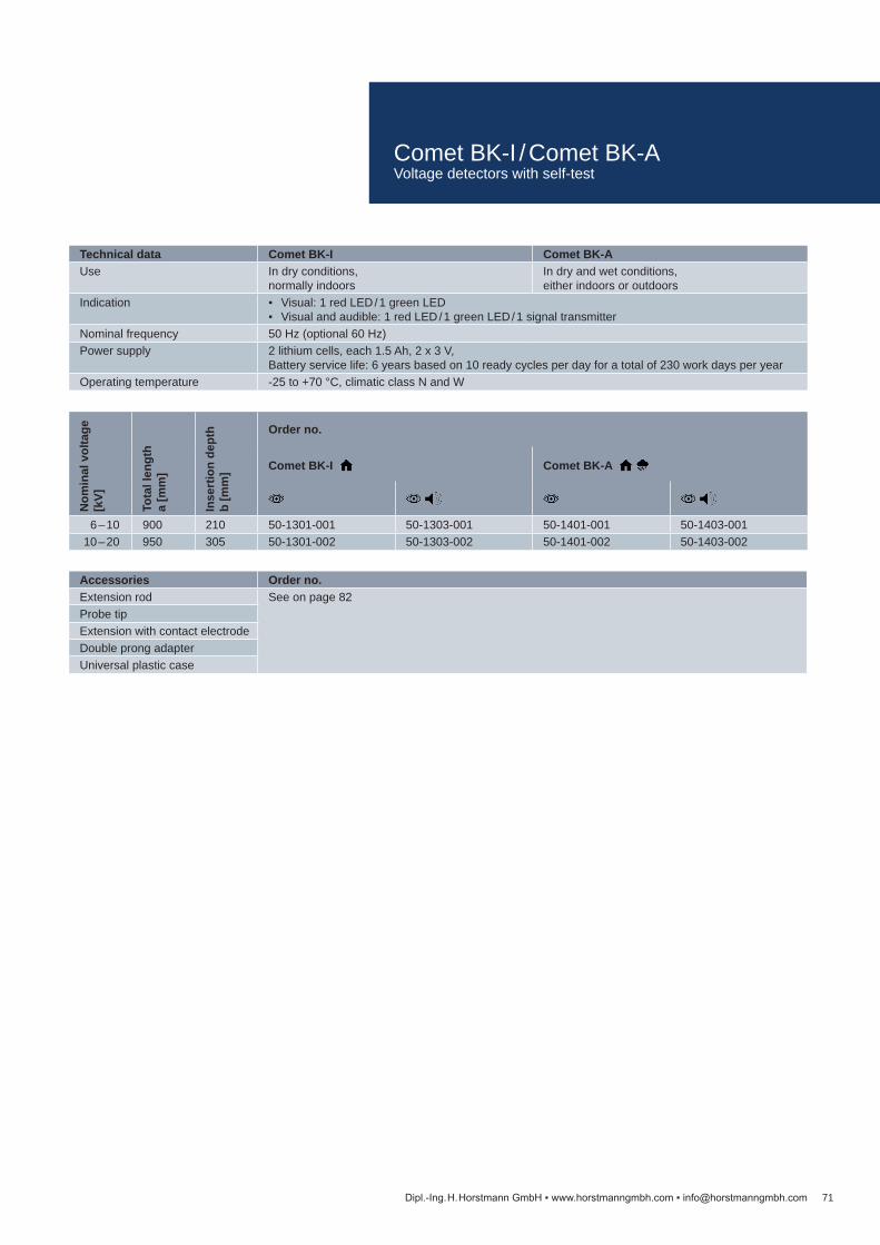
Technical data Comet BK-I Comet BK-AUse In dry conditions,
normally indoorsIn dry and wet conditions, either indoors or outdoors
Indication Visual: 1 red LED / 1 green LED Visual and audible: 1 red LED / 1 green LED / 1 signal transmitter
Nominal frequency 50 Hz (optional 60 Hz)Power supply 2 lithium cells, each 1.5 Ah, 2 x 3 V,
Battery service life: 6 years based on 10 ready cycles per day for a total of 230 work days per yearOperating temperature -25 to +70 °C, climatic class N and W
Nom
inal
vol
tage
[kV]
Tota
l len
gth
a [m
m]
Inse
rtio
n de
pth
b [m
m]
Order no.
Comet BK-I Comet BK-A
6 – 10 900 210 50-1301-001 50-1303-001 50-1401-001 50-1403-00110 – 20 950 305 50-1301-002 50-1303-002 50-1401-002 50-1403-002
Accessories Order no.Extension rod See on page 82Probe tipExtension with contact electrodeDouble prong adapterUniversal plastic case
71Dipl.-Ing. H. Horstmann GmbH www.horstmanngmbh.com [email protected]
Comet BK-I / Comet BK-AVoltage detectors with self-test
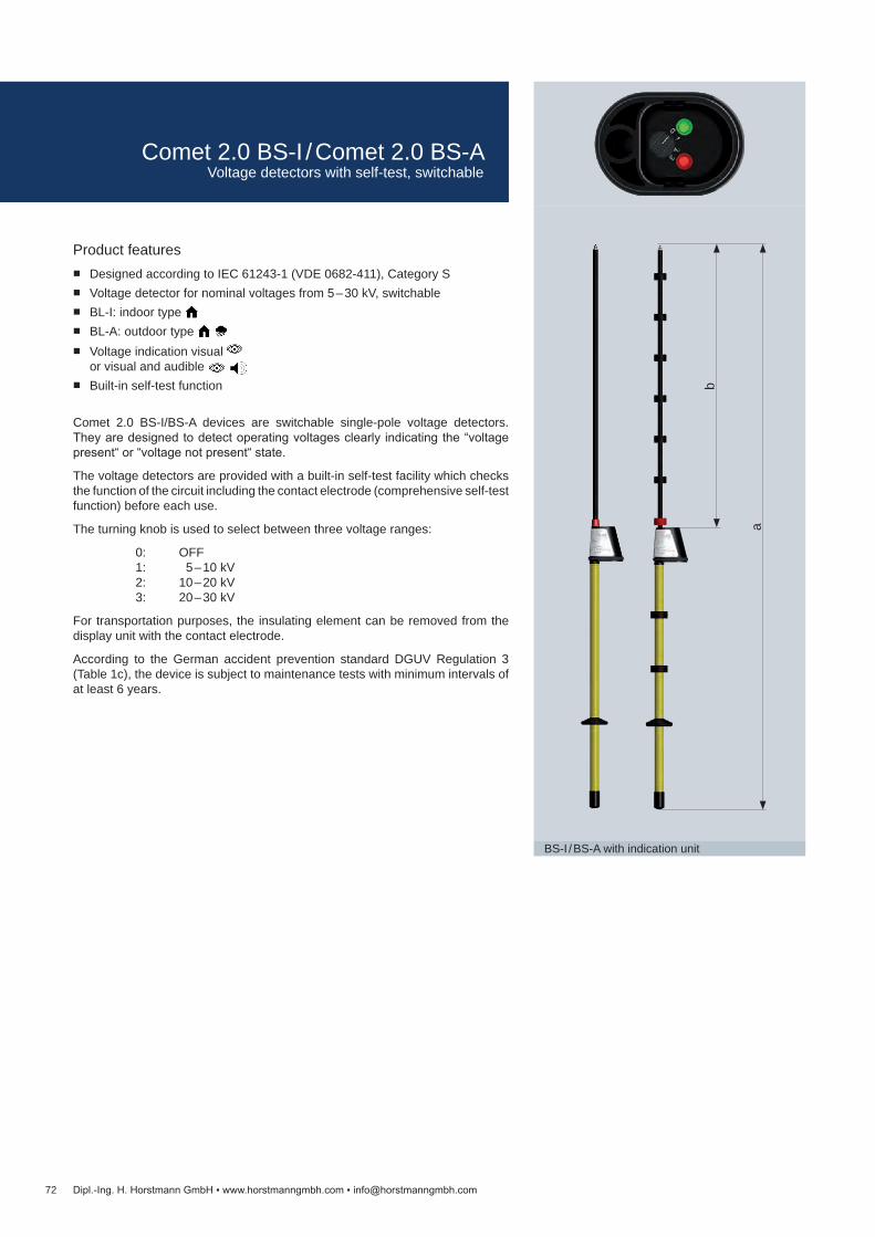
72
BS-I / BS-A with indication unit
Dipl.-Ing. H. Horstmann GmbH www.horstmanngmbh.com [email protected]
a
b
Product features Designed according to IEC 61243-1 (VDE 0682-411), Category S Voltage detector for nominal voltages from 5 – 30 kV, switchable BL-I: indoor type BL-A: outdoor type Voltage indication visual
or visual and audible Built-in self-test function
Comet 2.0 BS-I/BS-A devices are switchable single-pole voltage detectors. They are designed to detect operating voltages clearly indicating the “voltage present“ or “voltage not present“ state.
The voltage detectors are provided with a built-in self-test facility which checks the function of the circuit including the contact electrode (comprehensive self-test function) before each use.
The turning knob is used to select between three voltage ranges:
0: OFF 1: 5 – 10 kV 2: 10 – 20 kV 3: 20 – 30 kV
For transportation purposes, the insulating element can be removed from the display unit with the contact electrode.
According to the German accident prevention standard DGUV Regulation 3 (Table 1c), the device is subject to maintenance tests with minimum intervals of at least 6 years.
Comet 2.0 BS-I / Comet 2.0 BS-AVoltage detectors with self-test, switchable

Technical data Comet 2.0 BS-I Comet 2.0 BS-AUse In dry conditions,
normally indoorsIn dry and wet conditions, either indoors or outdoors
Indication Visual: 1 red LED / 1 green LED Visual and audible: 1 red LED / 1 green LED / 1 signal transmitter
Nominal frequency 50 Hz (optional 60 Hz)Power supply 2 lithium cells, each 1.5 Ah, 2 x 3 V,
Battery service life: 6 years based on 10 ready cycles per day for a total of 230 work days per yearOperating temperature -25 to +70 °C, climatic class N and W
Nom
inal
vol
tage
[kV]
Tota
l len
gth
a [m
m]
Inse
rtio
n de
pth
b [m
m]
Order no.
Comet 2.0 BS-I Comet 2.0 BS-A
5 – 30 1,570 758 50-0921-001 50-0923-001 50-1021-001 50-1023-001
Accessories Order no.Extension rod See on page 82Probe tipDouble prong adapterUniversal plastic case
73Dipl.-Ing. H. Horstmann GmbH www.horstmanngmbh.com [email protected]
Comet 2.0 BS-I / Comet 2.0 BS-AVoltage detectors with self-test, switchable

74
BO-A 2.0 (VDE version)
BO-A 2.0 (IEC version)
Dipl.-Ing. H. Horstmann GmbH www.horstmanngmbh.com [email protected]
Product features VDE version – according to VDE 0681-6
IEC version – according to IEC 61243-1 category S Pluggable system – minimal setup Integrated self-test – greater safety Light weight – easy handling and transportation Indoor, outdoor and wet weather – one product for all applications Length of 4.7 m – voltage detection from the ground
The BO-A 2.0 is a voltage detector for medium voltage railway overhead contact wires. It is designed to detect the absence or presence of voltage during mainte-nance work for example. The voltage detector BO-A 2.0 is especially developed for 16.7 Hz networks. If the voltage detector BO-A 2.0 is used in network with a deviating frequency, a visual and audible signal is activated. In this case the network situation must be verified.
The BO-A 2.0 is designed according to IEC 61243-1 resp. VDE 0681-6, depend-ing on the version. The voltage detector is ready for the international market.
According to the German accident prevention standard DGUV Regulation 3 (Table 1c), the device is subject to maintenance tests with minimum intervals of at least 6 years.
BO-A 2.0For railway overhead contact wires
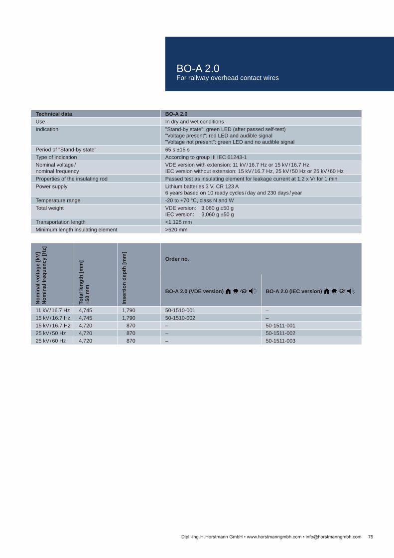
Technical data BO-A 2.0Use In dry and wet conditionsIndication "Stand-by state": green LED (after passed self-test)
"Voltage present": red LED and audible signal"Voltage not present": green LED and no audible signal
Period of "Stand-by state" 65 s ±15 sType of indication According to group III IEC 61243-1Nominal voltage / nominal frequency
VDE version with extension: 11 kV / 16.7 Hz or 15 kV / 16.7 HzIEC version without extension: 15 kV / 16.7 Hz, 25 kV / 50 Hz or 25 kV / 60 Hz
Properties of the insulating rod Passed test as insulating element for leakage current at 1.2 x Vr for 1 minPower supply Lithium batteries 3 V, CR 123 A
6 years based on 10 ready cycles / day and 230 days / yearTemperature range -20 to +70 °C, class N and WTotal weight VDE version: 3,060 g ±50 g
IEC version: 3,060 g ±50 gTransportation length <1,125 mmMinimum length insulating element >520 mm
Nom
inal
vol
tage
[kV]
N
omin
al fr
eque
ncy
[Hz]
Tota
l len
gth
[mm
] ±5
0 m
m
Inse
rtio
n de
pth
[mm
]
Order no.
BO-A 2.0 (VDE version) BO-A 2.0 (IEC version)
11 kV / 16.7 Hz 4,745 1,790 50-1510-001 –15 kV / 16.7 Hz 4,745 1,790 50-1510-002 –15 kV / 16.7 Hz 4,720 870 – 50-1511-00125 kV / 50 Hz 4,720 870 – 50-1511-00225 kV / 60 Hz 4,720 870 – 50-1511-003
75Dipl.-Ing. H. Horstmann GmbH www.horstmanngmbh.com [email protected]
BO-A 2.0For railway overhead contact wires
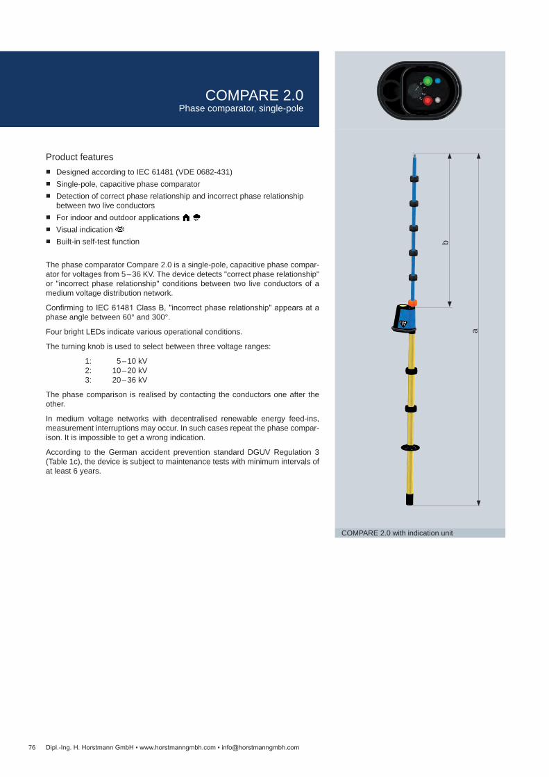
76
COMPARE 2.0 with indication unit
Dipl.-Ing. H. Horstmann GmbH www.horstmanngmbh.com [email protected]
Product features Designed according to IEC 61481 (VDE 0682-431) Single-pole, capacitive phase comparator Detection of correct phase relationship and incorrect phase relationship
between two live conductors For indoor and outdoor applications Visual indication Built-in self-test function
The phase comparator Compare 2.0 is a single-pole, capacitive phase compar-ator for voltages from 5 – 36 KV. The device detects "correct phase relationship" or "incorrect phase relationship" conditions between two live conductors of a medium voltage distribution network.
Confirming to IEC 61481 Class B, "incorrect phase relationship" appears at a phase angle between 60° and 300°.
Four bright LEDs indicate various operational conditions.
The turning knob is used to select between three voltage ranges:
1: 5 – 10 kV 2: 10 – 20 kV 3: 20 – 36 kV
The phase comparison is realised by contacting the conductors one after the other.
In medium voltage networks with decentralised renewable energy feed-ins, measurement interruptions may occur. In such cases repeat the phase compar-ison. It is impossible to get a wrong indication.
According to the German accident prevention standard DGUV Regulation 3 (Table 1c), the device is subject to maintenance tests with minimum intervals of at least 6 years.
a
b
COMPARE 2.0Phase comparator, single-pole

Technical data Compare 2.0Use In dry and wet conditions, either indoors or outdoorsIndication Visual: 1 white LED / 1 blue LED / 1 green LED / 1 red LEDNominal frequency 50 Hz Maximum operating period with the pole connected to voltage
60 s
Operating temperature -25 to +70 °C, climatic class N and WOperational class B (indication of phase unbalance in the range of 60° – 300°)
Nominal voltage [kV] Total length a [mm] Insertion depth b [mm] Order no. 5 – 36 1,420 635 51-0104-001
Accessories Order no.Universal plastic case See on page 82
Compare 2.0Equipment set 1 phase comparator
1 probe tip
77Dipl.-Ing. H. Horstmann GmbH www.horstmanngmbh.com [email protected]
COMPARE 2.0Phase comparator, single-pole
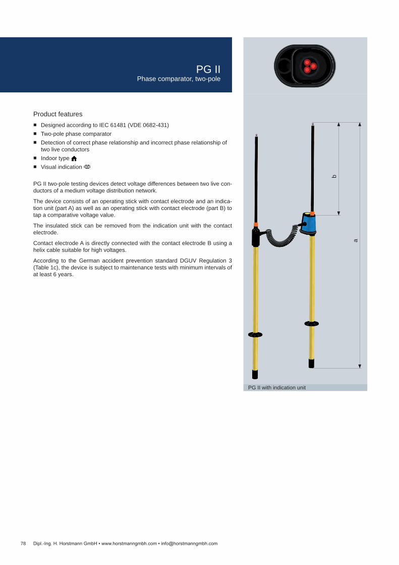
78
PG II with indication unit
Dipl.-Ing. H. Horstmann GmbH www.horstmanngmbh.com [email protected]
Product features Designed according to IEC 61481 (VDE 0682-431) Two-pole phase comparator Detection of correct phase relationship and incorrect phase relationship of
two live conductors Indoor type Visual indication
PG II two-pole testing devices detect voltage differences between two live con-ductors of a medium voltage distribution network.
The device consists of an operating stick with contact electrode and an indica-tion unit (part A) as well as an operating stick with contact electrode (part B) to tap a comparative voltage value.
The insulated stick can be removed from the indication unit with the contact electrode.
Contact electrode A is directly connected with the contact electrode B using a helix cable suitable for high voltages.
According to the German accident prevention standard DGUV Regulation 3 (Table 1c), the device is subject to maintenance tests with minimum intervals of at least 6 years.
a
b
PG IIPhase comparator, two-pole

Technical data PG IIUse In dry conditions, normally indoorsIndication Visual: 3 red LEDsNominal frequency 50 Hz (optional 60 Hz)Maximum operating period with the pole connected to voltage
60 s
Connection cable 1 mOperating temperature -25 to +70 °COperational class B (indication of phase unbalance in the range of 60° – 300°)
Nominal voltage [kV] Total length a (A or B) [mm] Insertion depth b [mm] Order no. 5 1,220 413 51-0102-001 6 1,220 413 51-0102-00210 1,220 413 51-0102-00320 1,320 513 51-0102-00430 1,420 613 51-0102-005
Accessories Order no.Probe tip See on page 82Universal plastic case
79Dipl.-Ing. H. Horstmann GmbH www.horstmanngmbh.com [email protected]
PG IIPhase comparator, two-pole
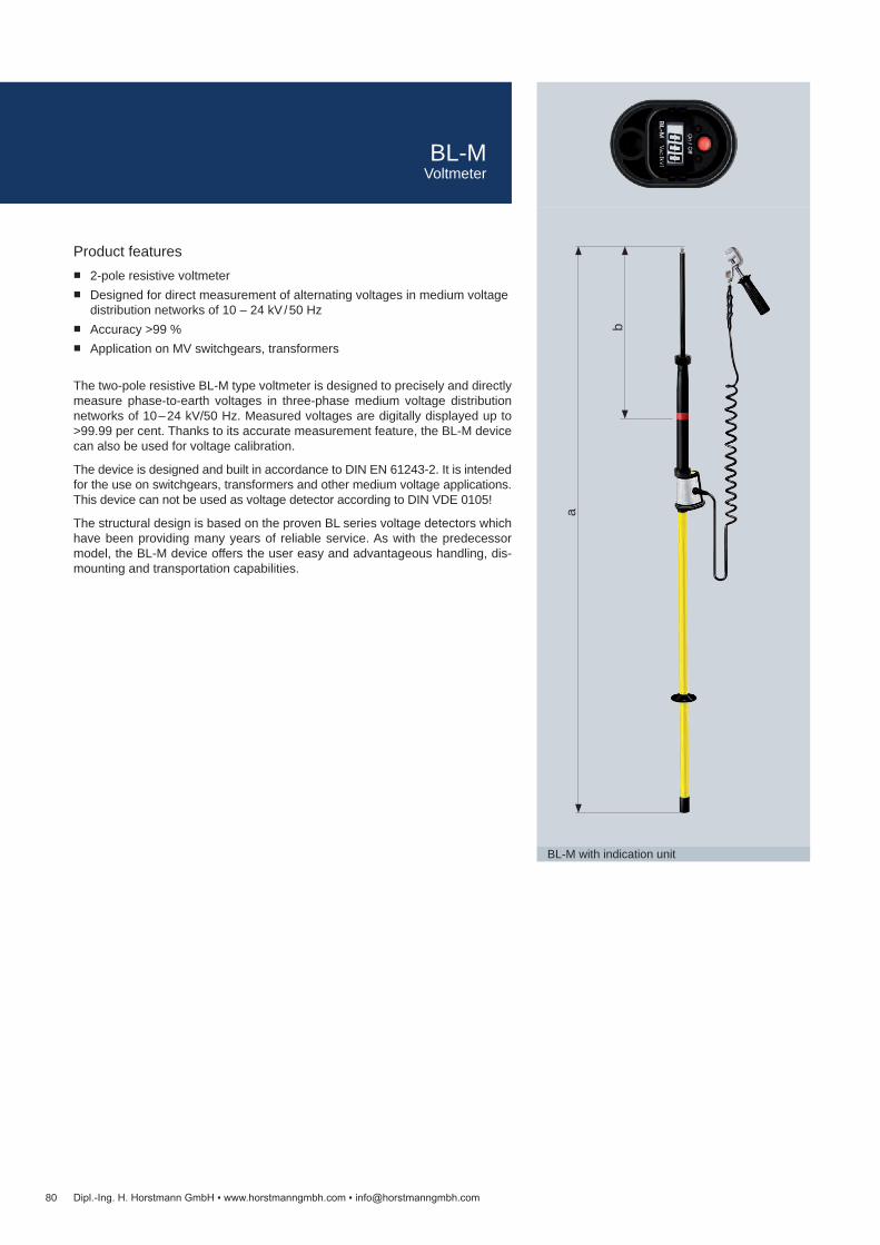
80
BL-M with indication unit
Dipl.-Ing. H. Horstmann GmbH www.horstmanngmbh.com [email protected]
Product features 2-pole resistive voltmeter Designed for direct measurement of alternating voltages in medium voltage
distribution networks of 10 – 24 kV / 50 Hz Accuracy >99 % Application on MV switchgears, transformers
The two-pole resistive BL-M type voltmeter is designed to precisely and directly measure phase-to-earth voltages in three-phase medium voltage distribution networks of 10 – 24 kV/50 Hz. Measured voltages are digitally displayed up to >99.99 per cent. Thanks to its accurate measurement feature, the BL-M device can also be used for voltage calibration.
The device is designed and built in accordance to DIN EN 61243-2. It is intended for the use on switchgears, transformers and other medium voltage applications. This device can not be used as voltage detector according to DIN VDE 0105!
The structural design is based on the proven BL series voltage detectors which have been providing many years of reliable service. As with the predecessor model, the BL-M device offers the user easy and advantageous handling, dis-mounting and transportation capabilities.
a
b
BL-MVoltmeter

Technical data BL-MApplication In dry conditions, normally indoorsIndication DisplayNominal frequency 50 – 60 Hz (optional 16.7 Hz)Measuring range 0.01 ... 19.99 kV AC (RMS)Resolution 0.01 kVMax. tolerance ±1 %, ±1 digitPower supply Block battery 9 V (lithium cell 9 V, 1,200 mAh)Duty cycle 10 min.Operating temperature 0 to +50 °CTotal length (a) 2,340 mmInsertion depth (b) ca. 570 mmEarthing connection cable Length: 3 mEarthing terminal Screw-type terminal
Article Order no.BL-M with connection cable and screw-type terminal, incl. universal plastic case, extension rod, test prod and double prong adapter
V99-0000-124-001
BL-M with connection cable and screw-type terminal 99-0000-124Extension rod, 500 mm See on page 82Test prodDouble prong adapterUniversal plastic case
81
Bag set
Dipl.-Ing. H. Horstmann GmbH www.horstmanngmbh.com [email protected]
BL-MVoltmeter
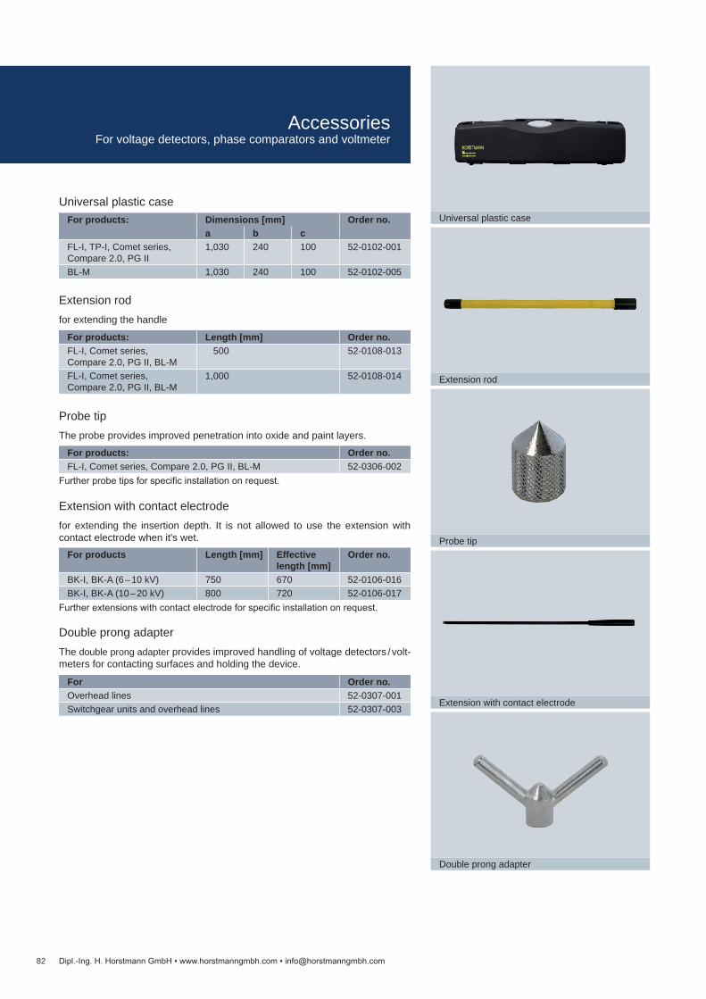
For Order no.Overhead lines 52-0307-001Switchgear units and overhead lines 52-0307-003
For products Length [mm] Effective length [mm]
Order no.
BK-I, BK-A (6 – 10 kV) 750 670 52-0106-016BK-I, BK-A (10 – 20 kV) 800 720 52-0106-017
For products: Order no.FL-I, Comet series, Compare 2.0, PG II, BL-M 52-0306-002
For products: Length [mm] Order no.FL-I, Comet series, Compare 2.0, PG II, BL-M
500 52-0108-013
FL-I, Comet series, Compare 2.0, PG II, BL-M
1,000 52-0108-014
For products: Dimensions [mm] Order no.a b c
FL-I, TP-I, Comet series, Compare 2.0, PG II
1,030 240 100 52-0102-001
BL-M 1,030 240 100 52-0102-005
82
Universal plastic case
Double prong adapter
Probe tip
Extension rod
Extension with contact electrode
Dipl.-Ing. H. Horstmann GmbH www.horstmanngmbh.com [email protected]
Double prong adapterThe double prong adapter provides improved handling of voltage detectors / volt-meters for contacting surfaces and holding the device.
Further extensions with contact electrode for specific installation on request.
Further probe tips for specific installation on request.
Extension rodfor extending the handle
Universal plastic case
Probe tipThe probe provides improved penetration into oxide and paint layers.
Extension with contact electrodefor extending the insertion depth. It is not allowed to use the extension with contact electrode when it's wet.
AccessoriesFor voltage detectors, phase comparators and voltmeter

Article Order no.Wega 1.2 C (base type without C2)
51-1250-001
Wega function tester 51-0211-010
Technical data Wega 1.2 CNominal frequency 50 – 60 HzInterface 3 LRM measuring sockets (one per phase) and 1 earth socket
LRM system, 14 mm distance between sockets, with captive anti-dust capIndication LCD display with arrow, dot and wrench toolPower supply No auxiliary supply needed
LCD display: fed by measuring voltageHousing Polycarbonate, IP54Temperature range -25 to +65 °C
83
WEGA 1.2 C
C1: Coupling capacitor
C2: Adaption capacitorCL: Cable capacity
LRM test socket
Voltage indication
Ground
ULE
L1L2L3
Principle of an integrated voltage detecting system
Dipl.-Ing. H. Horstmann GmbH www.horstmanngmbh.com [email protected]
Required order data: Switchgear type Switchgear compartment Operating voltage of the installation (Vnom) Capacity of the coupling electrode (C1) Cable type and length of the connection cable
Dimension drawing see on page 93, M16
Product features Designed according to IEC 61243-5 (VDE 0682-415) Wide-range Wega (e. g. 10 – 20 / 24 kV): Reduction of variants Integrated maintenance test: Maintenance-free Retrofit ready:
Capacitive connection to ComPass B and Sigma D series Front accessible LRM interface: Fully featured according to IEC 61243-5 Fully enclosed electronics: High functional reliability Over-voltage indication: Phase-selective
Wega 1.2 C is a 3-phase voltage detecting system, which indicates the following operating voltage states:
Voltage present Threshold values for voltage presence indication: 0.1 – 0.45 x Vnom
Voltage present Integrated maintenance test passed
Voltage present Integrated maintenance test passed Voltage signal too high (overvoltage indication)
Voltage not present
The built-in display test function at the front enables verification of the display of the installed and de-energised unit.
For connection, either shielded or unshielded cables with flat connectors or system connectors can be used.
WEGA 1.2 CIntegrated voltage detecting system
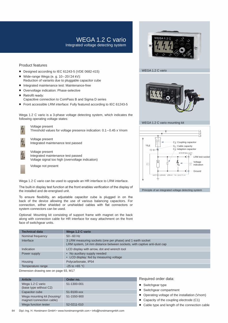
Technical data Wega 1.2 C varioNominal frequency 50 – 60 HzInterface 3 LRM measuring sockets (one per phase) and 1 earth socket
LRM system, 14 mm distance between sockets, with captive anti-dust capIndication LCD display with arrow, dot and wrench toolPower supply No auxiliary supply needed
LCD display: fed by measuring voltageHousing Polycarbonate, IP54Temperature range -25 to +65 °C
Article Order no.Wega 1.2 C vario (base type without C2)
51-1300-001
Capacitor cube 51-9100-xxxWega mounting kit (housing / magnet / connection cable)
51-1550-900
Wega function tester 52-0211-010
84
WEGA 1.2 C vario
C1: Coupling capacitor
C2: Adaption capacitorCL: Cable capacity
LRM test socket
Voltage indication
Ground
ULE
L1L2L3
Principle of an integrated voltage detecting system
WEGA 1.2 C vario mounting kit
Dipl.-Ing. H. Horstmann GmbH www.horstmanngmbh.com [email protected]
Dimension drawing see on page 93, M17
Product features Designed according to IEC 61243-5 (VDE 0682-415) Wide-range Wega (e. g. 10 – 20 / 24 kV):
Reduction of variants due to pluggable capacitor cube Integrated maintenance test: Maintenance-free Overvoltage indication: Phase-selective Retrofit ready:
Capacitive connection to ComPass B and Sigma D series Front accessible LRM interface: Fully featured according to IEC 61243-5
Wega 1.2 C vario is a 3-phase voltage detecting system, which indicates the following operating voltage states:
Voltage present Threshold values for voltage presence indication: 0.1 – 0.45 x Vnom
Voltage present Integrated maintenance test passed
Voltage present Integrated maintenance test passed Voltage signal too high (overvoltage indication)
Voltage not present
Wega 1.2 C vario can be used to upgrade an HR interface to LRM interface.
The built-in display test function at the front enables verification of the display of the installed and de-energised unit.
To ensure flexibility, an adjustable capacitor cube is plugged in on the back of the device allowing the use of various balancing capacitors. For connection, either shielded or unshielded cables with flat connectors or system connectors can be used.
Optional: Mounting kit consisting of support frame with magnet on the back along with connection cable for HR interface for easy attachment on the front face of switchgear units.
Required order data: Switchgear type Switchgear compartment Operating voltage of the installation (Vnom) Capacity of the coupling electrode (C1) Cable type and length of the connection cable
WEGA 1.2 C varioIntegrated voltage detecting system

Technical data Wega 2.2 CNominal frequency 50 – 60 HzInterface 3 LRM measuring sockets (one per phase) and 1 earth socket
LRM system, 14 mm distance between sockets, with captive anti-dust capIndication LCD display with arrow, dot and wrench tool
LED indication, U=0 and U≠0Remote signal 2 relay contacts, alternating contactPower supply LCD display: fed by measuring voltage
Relay via 24 – 230 V AC / DC power supplyHousing Polycarbonate, IP54Temperature range -25 to +65 °C
Article Order no.Wega 2.2 C (base type without C2)
51-2250-001
Wega function tester 52-0211-010
85
WEGA 2.2 C
C1: Coupling capacitor
C2: Adaption capacitorCL: Cable capacity
LRM test socket
Voltage indication
Ground
ULE
L1L2L3
Principle of an integrated voltage detecting system
Dipl.-Ing. H. Horstmann GmbH www.horstmanngmbh.com [email protected]
Product features Designed according to IEC 61243-5 (VDE 0682-415) Remote: 2 relay contacts Wide-range Wega (e. g. 10 – 20 / 24 kV): Reduction of variants Integrated maintenance test: Maintenance-free Retrofit ready:
Capacitive connection to ComPass B and Sigma D series Front accessible LRM interface: Fully featured according to IEC 61243-5 Fully enclosed electronics: High functional reliability Overvoltage indication: Phase-selective
Wega 2.2 C is a 3-phase voltage detecting system, which indicates the following operating voltage states:
Voltage present Threshold values for voltage presence indication: 0.1 – 0.45 x Vnom
Voltage present Integrated maintenance test passed
Voltage present Integrated maintenance test passed Voltage signal too high (overvoltage indication)
Voltage not present
Additional to the LCD display the Wega 2.2 C has 2 LEDs (green U=0 and red U≠0). With 2 relay contacts the voltage state can be remotely monitored. The built-in display test function at the front enables verification of the display of the installed and de-energised Wega 2.2 C.
For connection, either shielded or unshielded cables with flat connectors or system connectors can be used.
Required order data: Switchgear type Switchgear compartment Operating voltage of the installation (Vnom) Capacity of the coupling electrode (C1) Cable type and length of the connection cable
Dimension drawing see on page 93, M18
WEGA 2.2 CIntegrated voltage detecting system

Article Order no.Wega 3 51-1410-001
Technical data Wega 3Nominal frequency 50 – 60 HzInterface 3 LRM measuring sockets (one per phase) and 1 earth socket
LRM system, 14 mm distance between sockets, with captive anti-dust capIndication LCD display with arrow and dotPower supply No auxiliary supply needed
LCD display: fed by measuring voltageHousing Polycarbonate, IP54Temperature range -25 to +65 °C
86
WEGA 3
Dipl.-Ing. H. Horstmann GmbH www.horstmanngmbh.com [email protected]
Dimension drawing see on page 93, M19
Product features Designed according to IEC 61243-5 (VDE 0682-415) Continuous LCD indication: 3-phase Integrated maintenance test: Maintenance-free Fully enclosed electronics: High functional reliability
Wega 3 is a 3-phase voltage detecting system, which indicates the following operating voltage states:
Voltage present
Voltage present Integrated maintenance test passed
Voltage not present
For connection, either shielded or unshielded cables with flat connectors or sys-tem connectors can be used.
Required order data: Switchgear type Switchgear compartment Operating voltage of the installation (Vnom) Capacity of the coupling electrode (C1) Cable type and length of the connection cable
WEGA 3Integrated voltage detecting system

Technical data Wega T1Nominal frequency 50 – 60 HzInterface Interface or test socket not includedPower supply No auxiliary supply necessary
LCD display: fed by measuring voltageTemperature range -25 to +65 °COperating time Suitable for continuous operationHousing material PolycarbonateDimensions wall-mounted housing
125 x 75 x 75 mm (W x H x D)
Wega T1Equipment set 1 display unit
1 Wall-mounted housing 1 Set of coaxial cables: 3 m 1 Earth cable: 30 cm
Article Order no.Set V51-1200-001-13x1) (Order no. on request)
87
WEGA T1
Example of installation
Dipl.-Ing. H. Horstmann GmbH www.horstmanngmbh.com [email protected]
Product features Designed according to IEC 61243-5 (VDE 0682-415) Continuous LCD indication: 3-phase Suitable for Euromold elbow connectors (K) 158 LR, (K) 152 SR and M 400
LR / G as well as Pfisterer MSCE 250 A 24 with capacitive test points Integrated maintenance test: Maintenance-free
The Wega T1 is a 3-phase voltage detector for insulated medium voltage trans-formers safe for touching. It is installed in a surface mount housing for applica-tions in new and existing transformer stations. Besides conventional medium voltage transformers, these types are in particular ideally suited for remote me-dium voltage transformers, or in transformer stations/buildings with more than one transformer.
With regard to the response threshold values of the LCD display, the design of the Wega T1 is a Voltage Detecting System according to IEC 61243-5, with capacitive coupling to live parts. This system is designed for elbow con-nectors with capacitive voltage taps type Euromold (K) 158 LR, (K) 152 SR, M 400 LR/G and Pfisterer MSCE 250 A 24.
The self-monitoring capability of the display does not require periodic mainte-nance testing. The built-in display test function at the front enables verification of the display of the installed and de-energised unit.
The device is not provided with LRM interfaces or test points for phase compar-ison due to the weak capacitive coupling which is associated with the specific application of the devices.
Dimension drawing see on page 93, M20
1) Depends on the voltage level. Please provide data when ordering
WEGA T1For insulated medium voltage transformers

88
ORION M1
ORION 3.1
Dipl.-Ing. H. Horstmann GmbH www.horstmanngmbh.com [email protected]
Product features Designed according to IEC 61243-5 (VDE 0682-415) Voltage detector Phase comparator Interface detector Phase-sequence indicator with status RGB LED ORION M1 with additional functions
Harmonic voltage and current measurement Phase angle measurement LCD display Measured data storage, readable Data transmission via USB interface
ORION 3.1 and ORION M1 are testing and indication devices for voltage de-tecting, phase comparison and coupling part testing according to IEC 61243-5. They are used at LRM and HR interfaces in medium voltage switchgears.
The ORION M1 features a large LCD display with backlight. It allows easy read-ing of the measured values, e. g. current, phase angle and harmonic voltage measurements. The integrated USB interface is used to retrieve the stored data results for further evaluation.
Besides the information on the next maintenance test and the indication of the battery status, the ORION M1 device provides the user with menu language options (German/English).
Capacitive interface Precision current measurement in µA (2 x CH) Voltage testing symbols for both channels Maintenance tests on coupling parts Phase-sequence indication Frequency setting and battery status
Voltage accuracy FFT (Fast Fourier Transformation) Total harmonic distortion (THD) [%] Up to the 40th harmonic [%] Bar graph for harmonic voltage percentage
Phase comparison Phase angle difference Phase balance/phase unbalance symbol Phase-sequence indication
ORION 3.1 / ORION M1Combined voltage detection and indication systems

Technical data Orion 3.1 Orion M1Nominal frequency 50 or 60 Hz 16,7, 50, 60 Hz (adjustable)Current measurement — Measuring range 1: 0 – 5 µA (±2 %)
Measuring range 2: 0 – 25 µA (±2 %)Phase angle measurement — Measuring range: -180 to +180° (±1°)Harmonic voltage measurement
— Bar graph: 0 – 5 % / 0 – 10 % THD:0 – 100 % (±1 %) Harmonic (2-40): 0 – 100 % (±1 %)
Indication RGB-LEDs RGB LEDs LCD display
Power supply 4 mignon cells / LR 6 or AA 1.5 V; replaceable 6 years of service life, 1,000 operating cycles/year
Operating temperature -25 to +55 °C -25 to +55 °C, below -15 °C LED indication only
Article Order no.Orion 3.1 Orion M1
Set 51-0206-101 (50 Hz)51-0206-102 (60 Hz)
51-0206-201
LR-LRM adapter (for jack connectors)
52-0206-002
WEVA adapter Orion, 104 mm 52-0206-004 (10 kV), 52-0206-005 (20 kV)WEVA adapter Orion, 130 mm 52-0206-014 (10 kV), 52-0206-024 (20 kV)Special HR adapter (cable length approx. 0.1 m)
52-0206-007
Special IVIS adapter(cable length approx. 0.1 m)
52-0206-017
Magnetic holder 49-6001-010
Orion 3.1 Orion M1Equipment set Orion, plastic case, set of measuring lines, 2 HR / LRM adapter
Only Orion M1: USB cable + CD with application software + magnetic holder
89
Special HR adapter Special IVIS adapter Magnetic holder
LR-LRM adapter WEVA adapter 104 mm WEVA adapter 130 mm
Dipl.-Ing. H. Horstmann GmbH www.horstmanngmbh.com [email protected]
Dimension drawing see on page 93, M21
ORION 3.1 / ORION M1Combined voltage detection and indication systems

Technical data HR-ST LRM-STResponse voltage Vt 70 – 90 V 4 – 5 VNominal frequency 50 HzInput impedance 36.0 – 43.2 MΩ 2.0 – 2.4 MΩOperating temperature -25 to +55 °CFlash frequency ≥1 Hz upon trip voltageHousing Polycarbonate, IP54Circuit Sealed in cast resin, water-proof
Article Order no.HR-ST LRM-ST
Plug 51-0205-010 51-0205-011HR/LRM function tester 52-0211-007
90
HR-ST
LRM-ST
Function tester HR / LRM
Dipl.-Ing. H. Horstmann GmbH www.horstmanngmbh.com [email protected]
Product features Designed according to IEC 61243-5 (VDE 0682-415) HR-ST: Continuous voltage indicator for high-resistance systems LRM-ST: Continuous voltage indicator for low-resistance modified systems No battery supply Voltage is indicated by a flashing LED
HR-ST and LRM-ST type voltage indicators are mobile components of a voltage detecting system with capacitive single-pole coupling to live parts.
The HR/LRM function tester allows testing of the display and the overall function of the device.
HR-ST: Dimension drawing see on page 94, M22LRM-ST: Dimension drawing see on page 94, M23
HR-ST / LRM-STVoltage indicator for capacitive measuring points
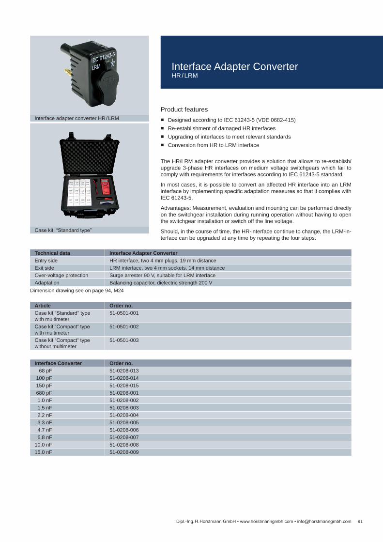
Technical data Interface Adapter ConverterEntry side HR interface, two 4 mm plugs, 19 mm distanceExit side LRM interface, two 4 mm sockets, 14 mm distanceOver-voltage protection Surge arrester 90 V, suitable for LRM interfaceAdaptation Balancing capacitor, dielectric strength 200 V
Article Order no.Case kit “Standard“ type with multimeter
51-0501-001
Case kit “Compact“ type with multimeter
51-0501-002
Case kit “Compact“ type without multimeter
51-0501-003
Interface Converter Order no. 68 pF 51-0208-013 100 pF 51-0208-014 150 pF 51-0208-015 680 pF 51-0208-001 1.0 nF 51-0208-002 1.5 nF 51-0208-003 2.2 nF 51-0208-004 3.3 nF 51-0208-005 4.7 nF 51-0208-006 6.8 nF 51-0208-00710.0 nF 51-0208-00815.0 nF 51-0208-009
91
Interface adapter converter HR / LRM
Case kit: “Standard type”
Dipl.-Ing. H. Horstmann GmbH www.horstmanngmbh.com [email protected]
Product features Designed according to IEC 61243-5 (VDE 0682-415) Re-establishment of damaged HR interfaces Upgrading of interfaces to meet relevant standards Conversion from HR to LRM interface
The HR/LRM adapter converter provides a solution that allows to re-establish/upgrade 3-phase HR interfaces on medium voltage switchgears which fail to comply with requirements for interfaces according to IEC 61243-5 standard.
In most cases, it is possible to convert an affected HR interface into an LRM interface by implementing specific adaptation measures so that it complies with IEC 61243-5.
Advantages: Measurement, evaluation and mounting can be performed directly on the switchgear installation during running operation without having to open the switchgear installation or switch off the line voltage.
Should, in the course of time, the HR-interface continue to change, the LRM-in-terface can be upgraded at any time by repeating the four steps.
Dimension drawing see on page 94, M24
Interface Adapter ConverterHR / LRM

Testing Requirements according to Test Interval Remark Order no.
Voltage detectors with capacitive coupling a)BL-I, BL-A, BK-I, BK-A, BS-I, BS-A DIN EN 61243-1 / VDE 0682 Part 411 6 years b), c), d) 79-0102-004BO-A (for railway systems) DIN VDE 0681 Part 6 6 years b), c), d)FL-I DIN EN 61243-1 / VDE 0682 Part 411 6 years b), c) 79-0110-001TP-I Based on DIN EN 61243-1 /
VDE 0682 Part 4116 years b), c) 79-0113-005
Phase comparators with capacitive couplingPG II DIN EN 61481 / VDE 0682 Part 431 6 years b), c), d) 79-0105-001Compare 2.0 DIN EN 61481 / VDE 0682 Part 431 6 years b), c), d) 79-0112-001Interface detectors, voltage detectors, phase comparatorsOrion 3.0, 3.1, M1 DIN EN 61243-5 / VDE 0682 Part 415 6 years c), d) 79-0107-001Capacitive continuous voltage indicators, pluggableHR-ST, LRM-ST DIN EN 61243-5 / VDE 0682 Part 415 6 years e) —Coupling parts of pluggable capacitive voltage detecting systemsJack Modules DIN EN 61243-5 / VDE 0682 Part 415
(latest and newer devices)6 years f) —
VoltmeterBL-M Based on DIN EN 61243-2 2 years g) 79-0107-020
92 Dipl.-Ing. H. Horstmann GmbH www.horstmanngmbh.com [email protected]
a.) Maintenance tests on devices belonging to the AC series are no longer carried out.
b.) All devices, which are sent to us by our customers, must be sent complete i. e. including operating sticks and extension elements.
c.) We perform maintenance test only on the condition that the devices are not older than 14 years and in a technically acceptable condition.
d.) For all battery-operated devices, the battery replacement is mandatory during maintenance test (included in the price).
e.) Due to the disproportionately high testing expenditure, we do not carry out maintenance tests on the HR-ST and LRM-ST devices. We replace these devices on a “new-for-old” basis granting a special discount of 20 % on the new price.
f.) Can be carried out on own initiative with the Orion 3.0, 3.1, M1. Orion 3.0, 3.1 conclude a good/bad condition. Further quantitative measurements can be carried out using HO-M and NO-M measuring adapters as well as appropri-ate digital multimeters.
g.) This test includes a metrological recalibration and maintenance test based on DIN EN 691243-2. We recommend the test every 2 years.
In order to avoid any delay in processing order, we kindly ask you to either attach a copy of your order letter to your consignment, or send us your order letter in due time.
As per German accident prevention regulations for electrical installations and equipment (DGUV Regulation 3) of Employers Liability Insurance Association, voltage detectors, phase comparators and pluggable capacitive voltage detect-ing systems are subject to maintenance tests at intervals not exceeding 6 years. Dipl. Ing. H. Horstmann GmbH offers this maintenance testing for all new but also for some older devices of own production.
Regardless of the duty to perform repeat testing, the following rule is mandatory for devices and equipment including voltage detectors: The user is responsible for the safe and proper condition of the devices. Prior to each use, the user must verify devices and equipment are suitable for proper function as well as checking for externally visible damages and defects.
Integrated capacitive voltage testing devices of the Wega series including Wega 1.2, 1.2 C, 2.2, 2.2 C, 1.2 C vario and T1 with self-test facility, are not subject to maintenance tests.
Maintenance Test
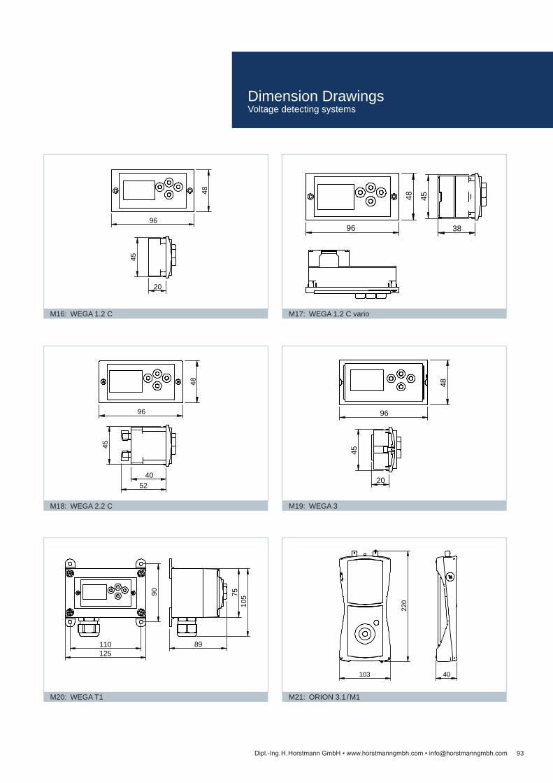
93
96
48
20
45
M16: WEGA 1.2 C
96
48
38
45
M17: WEGA 1.2 C vario
96
48
40 52
45
M18: WEGA 2.2 C
48
96
20
45
M19: WEGA 3
125
90
110 89
105
75
M20: WEGA T1
103
220
40
M21: ORION 3.1 / M1
Dipl.-Ing. H. Horstmann GmbH www.horstmanngmbh.com [email protected]
Dimension Drawings Voltage detecting systems

94
40
20
19
42
28
M22: HR-ST
20
40
14
42
28
M23: LRM-ST
24
41
30 50
19
14
M24: Interface converter
Dipl.-Ing. H. Horstmann GmbH www.horstmanngmbh.com [email protected]
Dimension Drawings Voltage detecting systems

Cable section [mm2] Short-circuit time tr = 0.5 s Short-circuit time tr = 1.0 sRated current Ir [kA] Peak factor Rated current Ir [kA] Peak factor
16 4.5 2.5 3.2 3.5 25 7.0 2.5 4.9 3.5 35 10.0 2.5 6.9 3.5 50 14.0 2.5 9.9 3.5 70 19.5 2.5 13.8 3.5 95 26.5 2.5 18.7 3.5120 33.5 2.5 23.7 3.5150 42.0 2.5 29.6 3.5
95Dipl.-Ing. H. Horstmann GmbH www.horstmanngmbh.com [email protected]
Earthing and short-circuiting devices are portable equipment for temporary earthing or earthing and short-circuiting of disconnected or isolated switchgear installations.
The aim of earthing and short-circuiting of disconnected or isolated parts in electrical installations is to prevent voltages and electric arcs in the event of an accidental re-closure or when currents are coupled into the system by adjacent energised installations.
Customers should bear in mind the following aspects:
Type of switchgear installation(s) Length of cables, or distance between phase and earth Type of neutral point connection of the installation
(whether or not solidly ground) Type of connection parts and determination of connection points
on conductors Rated short-circuit time tr Rated short-circuit current Ir Rated short-circuit peak factor
Recommended maintenance intervals for properly treated devices and equip-ment (according to BG ETEM):
at least every 5 years for equipment carried in vehicles at least every 10 years when installed in stationary equipment
Replacement is required for all devices
that were exposed at least one full short-circuit fault without or with insufficient transparency of cable insulation the insulation of which was originally transparent and colourless insulation
but has meanwhile discoloured such as to not allow identifying the condition of the copper strand, or
that are provided with welded or soldered connections.
Current and time rating for earthing equipmentWhen selecting the required cable cross section, the maximum short-circuit current of the switchgear installation must be taken into account. Connecting elements that are mounted to earthing and short-circuiting devices shall have at least the same current rating as the cables to which they are connected.
Earthing and short-circuiting devices and their components must be dimen-sioned in accordance with the short-circuit current rating (Ir), the short-circuit time rating (tr) and the corresponding peak factor.
Earthing Devices and AccessoriesGeneral information
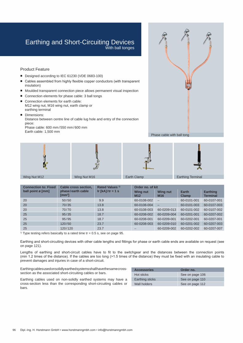
Accessories Order no.Hot sticks See on page 106Earthing sticks See on page 110Wall holders See on page 112
96
Phase cable with ball tong
Wing Nut M12 Wing Nut M16 Earth Clamp Earthing Terminal
Dipl.-Ing. H. Horstmann GmbH www.horstmanngmbh.com [email protected]
1) Type testing refers basically to a rated time tr = 0.5 s, see on page 95.
Earthing cables used on solidly earthed systems shall have the same cross- section as the associated short-circuiting cables or bars.
Earthing cables used on non-solidly earthed systems may have a cross-section less than the corresponding short-circuiting cables or bars.
Product Feature Designed according to IEC 61230 (VDE 0683-100) Cables assembled from highly flexible copper conductors (with transparent
insulation) Moulded transparent connection piece allows permanent visual inspection Connection elements for phase cable: 3 ball tongs Connection elements for earth cable:
M12 wing nut, M16 wing nut, earth clamp or earthing terminal
Dimensions: Distance between centre line of cable lug hole and entry of the connection piece: Phase cable: 600 mm / 550 mm / 600 mm Earth cable: 1,500 mm
Earthing and short-circuiting devices with other cable lengths and fittings for phase or earth cable ends are available on request (see on page 121).
Lengths of earthing and short-circuit cables have to fit to the switchgear and the distances between the connection points (min 1.2 times of the distance). If the cables are too long (>1.5 times of the distance) they must be fixed with an insulating cable to prevent damages and injuries in case of a short-circuit.
Connection to: Fixed ball point ø [mm]
Cable cross section, phase / earth cable [mm2]
Rated Values 1)
Ir [kA] / tr = 1 sOrder no. of kitWing nut M12
Wing nut M16
Earth Clamp
Earthing Terminal
20 50 / 50 9.9 60-0108-002 – 60-0101-001 60-0107-00120 70 / 35 13.8 60-0108-004 – 60-0101-003 60-0107-00320 70 / 70 13.8 60-0108-003 60-0209-013 60-0101-002 60-0107-00225 95 / 35 18.7 60-0208-002 60-0209-004 60-0201-001 60-0207-00225 95 / 95 18.7 60-0208-001 60-0209-001 60-0202-001 60-0207-00125 120 / 50 23.7 60-0208-003 60-0209-010 60-0201-002 60-0207-00325 120 / 120 23.7 – 60-0209-002 60-0202-002 60-0207-007
Earthing and Short-Circuiting DevicesWith ball tonges

Connection to:
Order no. of kit
Con
nect
ion
to
Fixe
d B
all P
oint
ø
[mm
]
T-C
onne
ctio
n B
olt
[mm
]
Rou
nd C
ondu
ctor
[m
m]
Flat
Con
duct
or
[mm
]
Cab
le C
ross
Sec
tion
Phas
e / E
arth
Cab
le
[mm
2 ]
Rat
ed V
alue
s 1)
I r
[kA
] / t r
= 1
s
Wing Nut M12
Wing Nut M16 Earth Clamp
Earthing Terminal
20 15 4 – 15 0 – 25 50 / 50 9.9 60-0308-001 – 60-0301-001 60-0307-00120 15 4 – 15 0 – 25 70 / 35 13.8 60-0308-003 – 60-0301-003 60-0307-00320 15 4 – 15 0 – 25 70 / 70 13.8 60-0308-002 – 60-0301-002 60-0307-00225 15 10 – 25 0 – 28 95 / 35 18.7 60-0508-002 – 60-0501-001 60-0507-00225 15 10 – 25 0 – 28 95 / 95 18.7 60-0508-001 60-0509-001 60-0502-001 60-0507-00125 15 10 – 25 0 – 28 120 / 50 23.7 60-0508-003 – 60-0501-002 60-0507-00325 15 10 – 25 0 – 28 120 / 120 23.7 – 60-0509-002 60-0502-002 –
Accessories Order no.Hot sticks See on page 106Earthing sticks See on page 110Wall holders See on page 112
97
Wing Nut M12 Wing Nut M16 Earth Clamp Earthing Terminal
Phase cable with universal phase clamp
Dipl.-Ing. H. Horstmann GmbH www.horstmanngmbh.com [email protected]
Product features Designed according to IEC 61230 (VDE 0683-100) Cables assembled from highly flexible copper conductors (with transparent
insulation) Moulded transparent connection piece allows permanent visual inspection Connection elements for phase cable:
Up to 70 mm² cross-section: 3 x universal compact clamps From 70 mm² cross-section: 3x universal phase clamps
Connection elements for earth cable: M12 wing nut, M16 wing nut, earth clamp or earthing terminal
Dimensions: Distance between centre line of cable lug hole and entry of the connection piece: Phase cable: 600 mm / 550 mm / 600 mm Earth cable: 1,500 mm
Earthing cables used on solidly earthed systems shall have the same cross- section as the associated short-circuiting cables or bars.
Earthing cables used on non-solidly earthed systems may have a cross-section less than the corresponding short-circuiting cables or bars.
Earthing and short-circuiting devices with other cable lengths and fittings for phase or earth cable ends are available on request (see on page 121).
Lengths of earthing and short-circuit cables have to fit to the switchgear and the distances between the connection points (min 1.2 times of the distance). If the cables are too long (>1.5 times of the distance) they must be fixed with an insulating cable to prevent damages and injuries in case of a short-circuit.
1) Type testing refers basically to a rated time tr = 0.5 s, see on page 95.
Earthing and Short-Circuiting DevicesWith universal phase clamp

Cross section of copper conductor [mm2]
Rated values1) Ir [kA] / tr = 1s
Cable length [mm]
Order no.
25 4.9 800 61-0101-015 25 4.9 2,000 61-0101-003 25 4.9 2,500 61-0101-016 35 6.9 2,000 61-0102-003 35 6.9 3,000 61-0102-009 50 9.9 1,200 61-0103-001 50 9.9 1,500 61-0103-002 50 9.9 2,000 61-0103-003 70 13.8 800 61-0104-018 70 13.8 1,200 61-0104-001 70 13.8 1,500 61-0104-002 70 13.8 2,000 61-0104-003 95 18.7 1,200 61-0105-001 95 18.7 1,500 61-0105-002 95 18.7 3,000 61-0105-009 95 18.7 4,000 61-0105-008 95 18.7 5,000 61-0105-010120 23.7 1,000 61-0106-012120 23.7 1,200 61-0106-001120 23.7 1,500 61-0106-002120 23.7 2,000 61-0106-003120 23.7 3,000 61-0106-006150 29.6 1,200 61-0107-001150 29.6 1,500 61-0107-002150 29.6 2,000 61-0107-003150 29.6 2,500 61-0107-009150 29.6 3,000 61-0107-006
98
Single-pole earthing and short-circuiting cable
Dipl.-Ing. H. Horstmann GmbH www.horstmanngmbh.com [email protected]
Product features Designed according to IEC 61230 (VDE 0683-1 or -100) Cables assembled from highly flexible copper conductors (with transparent
insulation) Cable lug on each cable end
Each cable lug is provided with a 13 mm dia. hole. Any type of connecting element can be used for the earthing cables (See on page 101 and 104).
Further cable lengths are available on request (see on page 121). 1) Type testing refers basically to a rated time of tr = 1 s and the peak factor of 2.5, see on page 95.
Lengths of earthing and short-circuit cables have to fit to the switchgear and the distances between the connection points (min 1.2 times of the distance). If the cables are too long (>1.5 times of the distance) they must be fixed with an insulating cable to prevent damages and injuries in case of a short-circuit.
Single-Pole Earthing and Short-Circuiting Cables
Without connecting elements
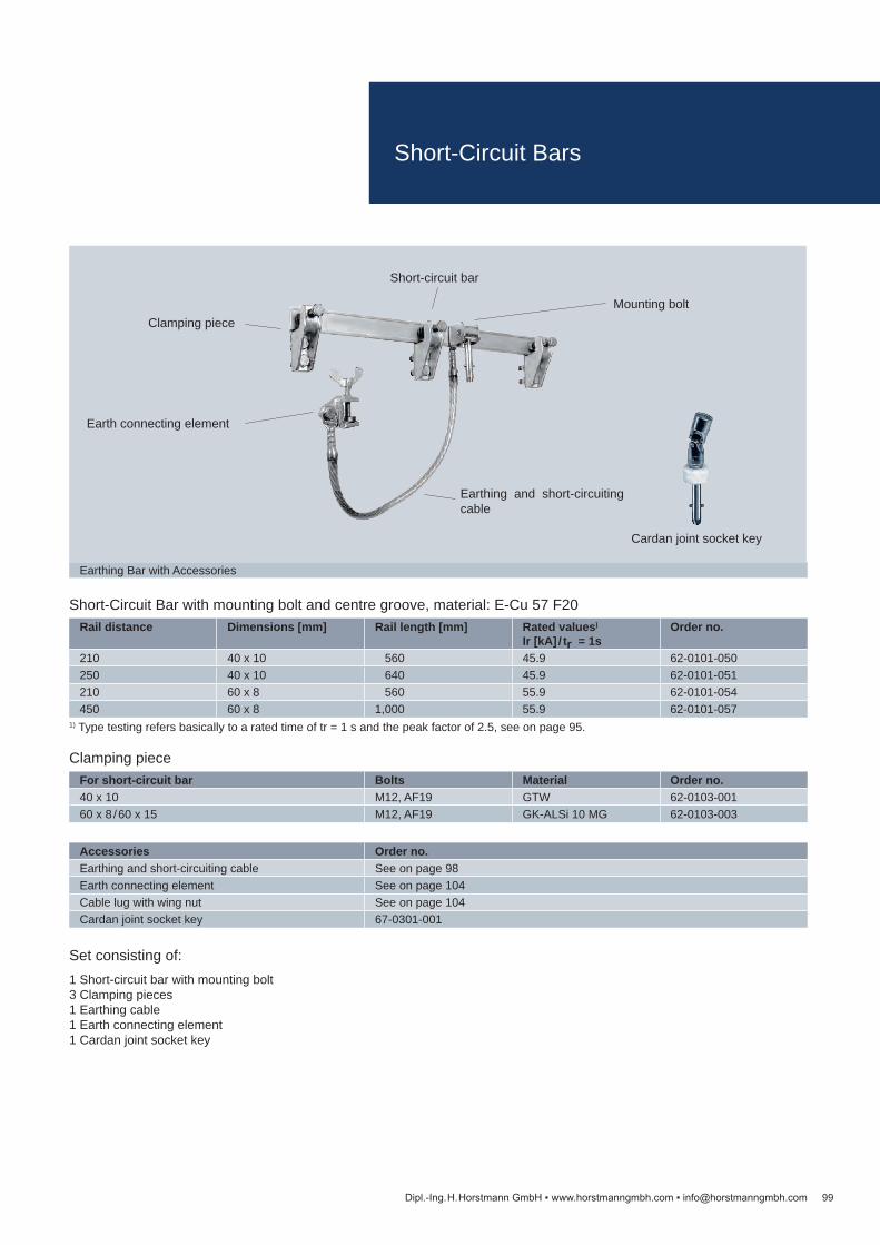
Accessories Order no.Earthing and short-circuiting cable See on page 98Earth connecting element See on page 104Cable lug with wing nut See on page 104Cardan joint socket key 67-0301-001
For short-circuit bar Bolts Material Order no.40 x 10 M12, AF19 GTW 62-0103-00160 x 8 / 60 x 15 M12, AF19 GK-ALSi 10 MG 62-0103-003
Rail distance Dimensions [mm] Rail length [mm] Rated values)
Ir [kA] / tr = 1sOrder no.
210 40 x 10 560 45.9 62-0101-050250 40 x 10 640 45.9 62-0101-051210 60 x 8 560 55.9 62-0101-054450 60 x 8 1,000 55.9 62-0101-057
99
Earthing Bar with Accessories
Short-circuit bar
Mounting bolt
Earthing and short-circuiting cable
Earth connecting element
Clamping piece
Cardan joint socket key
Dipl.-Ing. H. Horstmann GmbH www.horstmanngmbh.com [email protected]
Set consisting of:1 Short-circuit bar with mounting bolt 3 Clamping pieces 1 Earthing cable 1 Earth connecting element 1 Cardan joint socket key
Clamping piece
1) Type testing refers basically to a rated time of tr = 1 s and the peak factor of 2.5, see on page 95.
Short-Circuit Bar with mounting bolt and centre groove, material: E-Cu 57 F20
Short-Circuit Bars
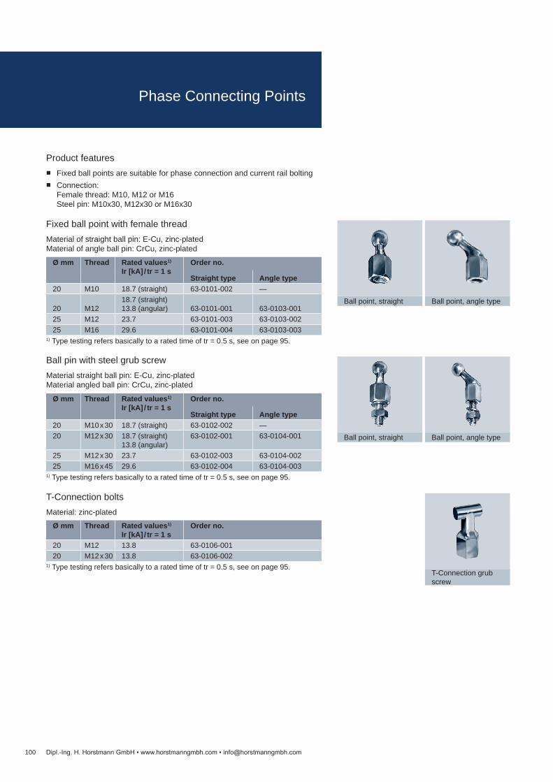
Ø mm Thread Rated values1)
Ir [kA] / tr = 1 sOrder no.
20 M12 13.8 63-0106-00120 M12 x 30 13.8 63-0106-002
Ø mm Thread Rated values1)
Ir [kA] / tr = 1 sOrder no.
Straight type Angle type20 M10 x 30 18.7 (straight) 63-0102-002 —20 M12 x 30 18.7 (straight)
13.8 (angular)63-0102-001 63-0104-001
25 M12 x 30 23.7 63-0102-003 63-0104-00225 M16 x 45 29.6 63-0102-004 63-0104-003
Ø mm Thread Rated values1)
Ir [kA] / tr = 1 sOrder no.
Straight type Angle type20 M10 18.7 (straight) 63-0101-002 —
20 M1218.7 (straight) 13.8 (angular) 63-0101-001 63-0103-001
25 M12 23.7 63-0101-003 63-0103-00225 M16 29.6 63-0101-004 63-0103-003
100
T-Connection grub screw
Ball point, angle typeBall point, straight
Ball point, angle typeBall point, straight
Dipl.-Ing. H. Horstmann GmbH www.horstmanngmbh.com [email protected]
1) Type testing refers basically to a rated time of tr = 0.5 s, see on page 95.
T-Connection boltsMaterial: zinc-plated
1) Type testing refers basically to a rated time of tr = 0.5 s, see on page 95.
Ball pin with steel grub screwMaterial straight ball pin: E-Cu, zinc-plated Material angled ball pin: CrCu, zinc-plated
1) Type testing refers basically to a rated time of tr = 0.5 s, see on page 95.
Fixed ball point with female threadMaterial of straight ball pin: E-Cu, zinc-plated Material of angle ball pin: CrCu, zinc-plated
Product features Fixed ball points are suitable for phase connection and current rail bolting Connection:
Female thread: M10, M12 or M16 Steel pin: M10x30, M12x30 or M16x30
Phase Connecting Points
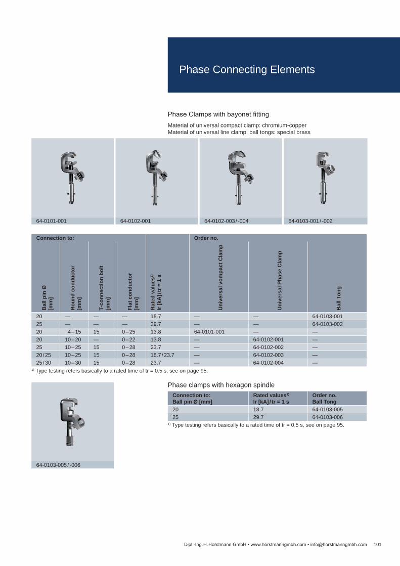
Connection to: Ball pin Ø [mm]
Rated values1)
Ir [kA] / tr = 1 sOrder no. Ball Tong
20 18.7 64-0103-00525 29.7 64-0103-006
Connection to:
Rat
ed v
alue
s1)
Ir [k
A] /
tr =
1 s
Order no.
Bal
l pin
Ø
[mm
]
Rou
nd c
ondu
ctor
[m
m]
T-co
nnec
tion
bolt
[mm
]
Flat
con
duct
or
[mm
]
Uni
vers
al v
ompa
ct C
lam
p
Uni
vers
al P
hase
Cla
mp
Bal
l Ton
g
20 — — — 18.7 — — 64-0103-00125 — — — 29.7 — — 64-0103-00220 4 – 15 15 0 – 25 13.8 64-0101-001 — —20 10 – 20 — 0 – 22 13.8 — 64-0102-001 —25 10 – 25 15 0 – 28 23.7 — 64-0102-002 —20 / 25 10 – 25 15 0 – 28 18.7 / 23.7 — 64-0102-003 —25 / 30 10 – 30 15 0 – 28 23.7 — 64-0102-004 —
101
64-0103-005 / -006
64-0101-001 64-0102-001 64-0102-003 / -004 64-0103-001 / -002
Dipl.-Ing. H. Horstmann GmbH www.horstmanngmbh.com [email protected]
1) Type testing refers basically to a rated time of tr = 0.5 s, see on page 95.
Phase clamps with hexagon spindle
1) Type testing refers basically to a rated time of tr = 0.5 s, see on page 95.
Phase Clamps with bayonet fittingMaterial of universal compact clamp: chromium-copper Material of universal line clamp, ball tongs: special brass
Phase Connecting Elements

Connection point for EKV [mm2]
Rated values1)
Ir [kA] / tr = 1 sOrder no.
M12 18.7 63-0204-001
Fixing in switchgears [mm]
Rated values1)
Ir [kA] / tr = 1 sOrder no.Welding type with steel pin with female thread
— 18.7 63-0201-001 — —M12 x 25 18.7 — 63-0201-007 —M12 x 40 18.7 — 63-0201-006 —M12 18.7 — — 63-0201-003
102
Welding type with steel pin with female thread
Welding Bolt
Dipl.-Ing. H. Horstmann GmbH www.horstmanngmbh.com [email protected]
1) Type testing refers basically to a rated time of tr = 0.5 s, see on page 95.
Welding earthing nutfor cable lug with captive wing nut or with 13 mm bore hole (see on page 104 and 105). Material: steel, zinc-plated
Earth connecting bolts with ring groovefor earthing terminal (See on page 104) Material: brass, zinc-plated
Earth Connecting Points

Thread [mm2] Spanner size Rated values1) Ir [kA] / tr = 1 s
Order no.Female thread Bolt threadM12 M12 32 9.9 63-0206-001M12 M16 x 30 32 9.9 63-0206-003M16 M12 x 25 32 9.9 63-0206-002
Thread [mm2] Spanner size Rated values1) Ir [kA] / tr = 1 s
Order no.
M12 to M16 32 9.9 63-0205-003
Fixing Point for EKV [mm2] Spanner size Rated values1) Ir [kA] / tr = 1 s
Order no.
M12 x 60 32 13.8 63-0205-001M16 x 70 32 18.7 63-0205-002
103
Earthing Nut
Screw for crossed wires
Earthing Screw
Dipl.-Ing. H. Horstmann GmbH www.horstmanngmbh.com [email protected]
Earthing screwfor cable lug with captive wing nut (See on page 104) Material: brass, zinc-plated
Earthing screw for convertingfor cable lug with captive wing nut (see on page 104). Material: brass, zinc-plated
1) Type testing refers basically to a rated time of tr = 0.5 s, see on page 95.
Earthing nutfor cable lug with captive wing bolt (see on page 105). Material: brass, zinc plated
1) Type testing refers basically to a rated time of tr = 0.5 s, see on page 95.
1) Type testing refers basically to a rated time of tr = 0.5 s, see on page 95.
Earth Connecting Points

Cable cross section [mm2]
Thread Rated values1) Ir [kA] / tr = 1 s
Order no.
50 M12 9.9 64-0203-00170 M12 13.8 64-0203-00295 M12 18.7 64-0203-003
Clamping range [mm] Rated values1) Ir [kA] / tr = 1 s
Order no.with T-handle with wing bolt with bayonet connector
23 18.7 64-0201-001 64-0201-003 64-0201-00538 29.6 64-0201-002 64-0201-004 64-0201-006
Cable cross section [mm2]
Rated values1) Ir [kA] / tr = 1 s
Order no.
50 9.9 64-0202-00370 13.8 64-0202-00495 18.7 64-0202-005
104
with wing bolt with bayonet connectorwith T-handle
Cable lug
Earthing terminal
Dipl.-Ing. H. Horstmann GmbH www.horstmanngmbh.com [email protected]
Earthing terminalMaterial: brass / handle made of PA 6
1)Type testing refers basically to a rated time of tr = 0.5 s, see on page 95.
1) Type testing refers basically to a rated time of tr = 0.5 s, see on page 95.
1) Type testing refers basically to a rated time of tr = 0.5 s, see on page 95.
Cable lug with captive wing nut
Earth clampsMaterial: chromium-copper
Earth Connecting Elements

Connection to: Rated values1) Ir [kA] / tr = 1 s
Order no.Fixed ball point Ø [mm]
Round conductor [mm]
T-connection bolt [mm]
Flat conductor [mm]
25 10 – 25 0 – 28 0 – 28 23.7 64-0102-007
Cable cross section [mm2] Rated values1) Ir [kA] / tr = 1 s
Order no.
70 13.8 64-0205-004
Cable cross section [mm2] Thread Rated values1) Ir [kA] / tr = 1 s
Order no.
50 M12 x 15 9.9 64-0204-00170 M12 13.8 64-0204-00295 M12 18.7 64-0204-003
105
Universal earth clamp
Cable lug
Cable lug
Dipl.-Ing. H. Horstmann GmbH www.horstmanngmbh.com [email protected]
1) Type testing refers basically to a rated time of tr = 0.5 s, see on page 95.
1) Type testing refers basically to a rated time of tr = 0.5 s, see on page 95.
1) Type testing refers basically to a rated time of tr = 0.5 s, see on page 95.
Universal earth clamp with handle
Cable lug with 13 mm ø hole
Cable lug with captive wing bolt
Earth Connecting Elements
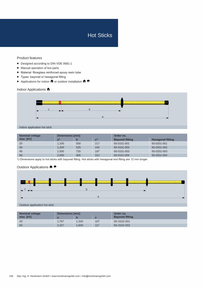
Nominal voltagemax. [kV]
Dimensions [mm] Order no.Bayonet fittinga b c
30 1,707 1,200 107 65-0102-00160 2,317 1,600 117 65-0102-002
Nominal voltage max. [kV]
Dimensions [mm] Order no.a1) b c1) Bayonet fitting Hexagonal fitting
20 1,100 500 217 65-0101-001 65-0201-00130 1,200 525 242 65-0101-002 65-0201-00245 1,500 720 197 65-0101-003 65-0201-00360 2,000 905 312 65-0101-004 65-0201-004
106
Outdoor application hot stick
b
a
c
Indoor application hot stick
a
bc
Dipl.-Ing. H. Horstmann GmbH www.horstmanngmbh.com [email protected]
Product features Designed according to DIN VDE 0681-1 Manual operation of live parts Material: fibreglass reinforced epoxy resin tube Types: bayonet or hexagonal fitting Applications for indoor or outdoor installation
1) Dimensions apply to hot sticks with bayonet fitting. Hot sticks with hexagonal end fitting are 12 mm longer.
Outdoor Applications
Indoor Applications
Hot Sticks
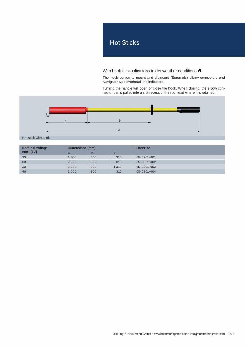
Nominal voltagemax. [kV]
Dimensions [mm] Order no.a b c
20 1,200 500 310 65-0301-00130 2,000 900 310 65-0301-00230 3,000 900 1,310 65-0301-00346 2,000 900 310 65-0301-004
107
Hot stick with hook
a
bc
Dipl.-Ing. H. Horstmann GmbH www.horstmanngmbh.com [email protected]
With hook for applications in dry weather conditions The hook serves to mount and dismount (Euromold) elbow connectors and Navigator type overhead line indicators.
Turning the handle will open or close the hook. When closing, the elbow con-nector bar is pulled into a slot recess of the rod head where it is retained.
Hot Sticks

Nominal voltagemax. [kV]
Dimensions [mm] Order no.a b c
20 1,120 505 215 65-0401-00130 1,220 525 245 65-0401-00245 1,520 720 200 65-0401-00360 2,020 900 320 65-0401-004
Nominal voltagemax. [kV]
Dimensions [mm] Order no.a b c d
20 1,120 500 220 600 65-0403-00145 1,520 720 200 800 65-0403-00360 2,020 900 320 1,050 65-0403-004
108
Indoor application operating rod
a
bc
Indoor application operating rod (two-part-design)
a
bc
d
Dipl.-Ing. H. Horstmann GmbH www.horstmanngmbh.com [email protected]
Indoor Applications
Product features Designed according to VDE 0681-2 (DIN 57681-2) Used to switch on and off switches with ring eyes Material: fibreglass reinforced epoxy resin tube One-part and two-part pluggable design Applications for indoor and outdoor installation
Indoor Applications , two-part design With lock pin.
Operating Rods

Accessories Order no.Switch hook with bayonet fitting 67-0301-003
Nominal voltagemax. [kV]
Dimensions [mm] Order no.a b c
20 1,520 1,000 120 65-0402-00130 1,720 1,200 120 65-0402-00245 2,180 1,400 180 65-0402-00360 2,320 1,600 120 65-0402-004
109
Switch hook
Outdoor application operating rod
a
bc
Dipl.-Ing. H. Horstmann GmbH www.horstmanngmbh.com [email protected]
Outdoor Applications
Switch hook with bayonet fittingSuitable for all operating rods (bayonet fitting according to DIN 48087)
Operating Rods

Dimensions [mm] Order no.a1) b1) Bayonet fitting Hexagon fitting1,117 717 66-0101-001 66-0201-0011,517 917 66-0101-002 66-0201-0022,017 1,217 66-0101-003 66-0201-003
110
Indoor application earthing stick
a
b
Dipl.-Ing. H. Horstmann GmbH www.horstmanngmbh.com [email protected]
Product features Designed according to VDE 0683-100 (IEC 61230) For installation and removal of earthing and short-circuiting devices in high-
voltage installations Material: fibreglass reinforced epoxy resin tube Types with bayonet or hexagon fitting Application for indoor installations
The insulating element of the earthing stick must be of adequate dimension to avoid inadmissible high leakage currents. The minimum length of the insulating element is 500 mm.
1) Dimensions apply to hot sticks with bayonet fitting. Hot sticks with hexagonal end fitting are 12 mm longer.
Earthing Sticks

Total length [mm] Order no.305 65-0504-004385 65-0504-001
Nominal Voltagemax. [kV]
Dimensions [mm] Clamping Range[mm]
Order no.a b c
1 – 30 1,010 525 400 50 – 90 65-0502-002
111
Tool
Fuse tong type K
a
b c
Dipl.-Ing. H. Horstmann GmbH www.horstmanngmbh.com [email protected]
Tools for fuses
Product features Designed according to VDE 0681-3 (DIN 57681-3) For gripping and replacing high-voltage HH fuses
The fuse tongs are guided over the fuses from the front, thus requiring little space to the side. They are ideally suited for use in narrow installations. The clamps are fixed and released by turning the handle.
Fuse Tongs

For holding:
Eart
hing
and
sho
rt-
circ
uitin
g de
vice
s
Eart
hing
stic
ks
Ope
ratin
g ro
ds
Hot
stic
ks
Fuse
tong
s
FL-I
TP-I
Com
et B
L-I /
Com
et B
L-A
Com
et B
K-I
/ Com
et B
K-A
Com
et 2
.0 B
S-I /
C
omet
2.0
BS-
A
HH
Fus
es
Ord
er n
o.
67-0101-001 67-0101-002
52-0105-002 67-0101-014
67-0101-015 67-0101-006
52-0105-001 67-0101-007
112
67-0101-014 (set) 67-0101-015 (set) 52-0105-001/ 67-0101-007
67-0101-001 67-0101-002 52-0105-002
Dipl.-Ing. H. Horstmann GmbH www.horstmanngmbh.com [email protected]
Wall Holders

Accessories Order no.Safety helmet without face shield 67-0202-002Safety helmet with face shield 67-0202-003High-grade protective helmet, without face shield 67-0202-012High-grade protective helmet, with face shield 67-0202-013Protective gloves for electricians, 1,000 V according to VDE 0680-1 with certification stamp, length: 350 mm, thickness: 0.7 mm
67-0202-005
Red / white plastic chain with nylon links 67-0202-001Rubber insulating matting up to 50 kV, max. 1 m wide, 4 mm thick, 10 m long (delivered as a roll – no tailored sizes)
67-0202-004
LED work lamp, incl. wall-mounting charge station3 W LED lamp with maintenance-free lead-acid battery, charge status display, flashing function and emergency light function
67-0202-010
Handheld fire extinguisher filled with 5 kg of carbon dioxid, with snow pipe and wall holder 67-0202-007
113
67-0202-003 67-0202-010 67-0202-007
67-0202-003 67-0202-005 67-0202-001
Dipl.-Ing. H. Horstmann GmbH www.horstmanngmbh.com [email protected]
Accessories

Article Order no.Insulating protective barrier on requestHot stick See on page 106
Technical data Insulating Protective BarrierMaterial PVC hard DIN 16927Colour Red, similar RAL 3000Plate thickness <30 kV, 6 mmSpec. insulation resistance 1015 Ω cmSurface resistivity 1011 Ω
114 Dipl.-Ing. H. Horstmann GmbH www.horstmanngmbh.com [email protected]
Product features Designed according to VDE 0682-552 Provides partial protection against direct contact
Insulating protective barriers are intended for short-term use in electrical indoor switchgears exceeding voltage ratings from 1 kV bis 30 kV AC.
These devices may be used in factory-built, type-tested switchgears only in compliance with the switchgear manufacturer’s instructions.
Insulating protective barriers are designed for partial protection against direct touching. These components do not protect against reclosure and must not touch live parts when installed.
According to requirement and application, numerous types of insulating pro-tective barriers are necessary. They are installed manually by hand or using an insulating or operating stick.
Appropriate holders or guide rails shall be provided.
Depending on the size and type of barrier, reinforcements in the form of U- sections are installed at the bottom of the barrier to prevent the component from being bent.
Insulating Protective Barrier
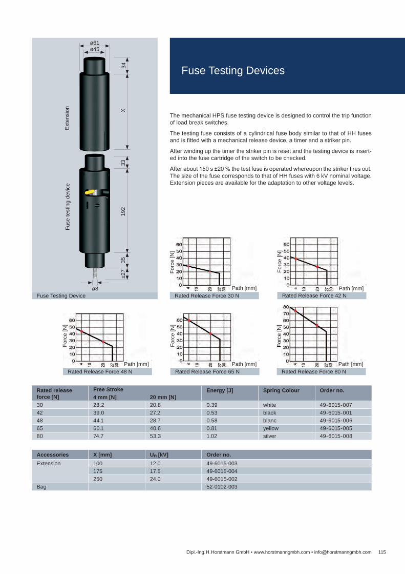
Rated release force [N]
Free Stroke Energy [J] Spring Colour Order no.4 mm [N] 20 mm [N]
30 28.2 20.8 0.39 white 49-6015-00742 39.0 27.2 0.53 black 49-6015-00148 44.1 28.7 0.58 blanc 49-6015-00665 60.1 40.6 0.81 yellow 49-6015-00580 74.7 53.3 1.02 silver 49-6015-008
Accessories X [mm] Un [kV] Order no.Extension 100 12.0 49-6015-003
175 17.5 49-6015-004250 24.0 49-6015-002
Bag 52-0102-003
115
Rated Release Force 30 NPath [mm]
Forc
e [N
]
Rated Release Force 42 NPath [mm]
Forc
e [N
]
Rated Release Force 48 NPath [mm]
Forc
e [N
]
Rated Release Force 65 NPath [mm]
Forc
e [N
]
Rated Release Force 80 NPath [mm]
Forc
e [N
]
Fuse Testing Device
192
33
ø61
ø8
X35
Fuse
test
ing
devi
ceE
xten
sion
ø45
34±2
7
Dipl.-Ing. H. Horstmann GmbH www.horstmanngmbh.com [email protected]
The mechanical HPS fuse testing device is designed to control the trip function of load break switches.
The testing fuse consists of a cylindrical fuse body similar to that of HH fuses and is fitted with a mechanical release device, a timer and a striker pin.
After winding up the timer the striker pin is reset and the testing device is insert-ed into the fuse cartridge of the switch to be checked.
After about 150 s ±20 % the test fuse is operated whereupon the striker fires out. The size of the fuse corresponds to that of HH fuses with 6 kV nominal voltage. Extension pieces are available for the adaptation to other voltage levels.
Fuse Testing Devices

Order No. Total [kg]
Cu[kg]
Ms[kg]
49-6015-002 1.00 – –49-6015-003 0.38 – –49-6015-004 0.70 – –49-6015-005 1.50 – –49-6015-006 1.50 – –49-6015-007 1.50 – –49-6015-008 1.50 – –49-6023-005 0.8049-6023-020 1.08 – –49-6024-001 0.36 – –49-6024-010 0.27 – –49-6025-000 0.33 – –49-6025-301 0.60 – –49-6025-311 0.60 – –49-6025-601 0.60 – –49-6025-602 0.28 – –49-6025-611 0.60 – –49-6025-612 0.60 – –49-9001-001 0.30 – –49-9001-002 0.30 – –49-9001-006 0.24 – –50-0901-011 0.81 – –50-0901-012 0.81 – –50-0901-013 0.84 – –50-0901-014 0.84 – –50-0901-015 0.87 – –50-0901-022 0.90 – –50-0903-008 0.80 – –50-0903-009 0.80 – –50-0903-010 0.83 – –50-0903-011 0.85 – –50-0903-012 0.89 – –50-0903-018 0.88 – –50-0921-001 0.89 – –50-0923-001 0.90 – –50-1001-009 0.90 – –50-1001-010 0.90 – –50-1001-011 1.00 – –50-1001-012 1.00 – –50-1001-013 1.05 – –50-1001-015 1.06 – –50-1003-009 0.85 – –50-1003-010 0.90 – –50-1003-011 1.00 – –50-1003-012 0.95 – –50-1003-013 1.05 – –50-1003-018 1.00 – –50-1021-001 1.05 – –50-1023-001 1.05 – –50-1201-001 0.80 – –50-1201-002 0.80 – –50-1201-003 0.82 – –50-1301-001 0.70 – –
Order No. Total [kg]
Cu[kg]
Ms[kg]
38-0152-001 0.20 – –38-4102-001 0.24 – –38-4150-001 0.31 – –38-4153-001 0.30 – –38-9100-013 3.10 – –38-9100-017 3.48 – –38-9100-026 7.56 – –41-2101-111 0.47 – –41-2101-211 0.47 – –41-2101-311 0.47 – –41-2101-511 0.47 – –41-2108-111 0.47 – –41-2108-211 0.47 – –41-2108-311 0.47 – –41-2108-511 0.47 – –49-0101-202 0.12 – –49-0101-203 0.14 – –49-0101-206 0.15 – –49-0109-002 0.08 – –49-0109-003 0.013 – –49-0602-001 0.02 – –49-0602-009 0.02 – –49-0701-010 0.25 – –49-0702-005 0.28 – –49-0702-010 0.51 – –49-0702-015 0.52 – –49-0704-001 0.25 – –49-0706-001 0.25 – –49-0921-002 0.22 – –49-6001-002 0.39 – –49-6001-010 0.03 – –49-6010-011 0.16 – –49-6010-030 0.14 – –49-6010-032 0.35 – –49-6010-044 0.15 – –49-6010-048 0.14 – –49-6010-052 0.12 – –49-6010-060 0.14 – –49-6011-040 0.27 – –49-6011-043 0.48 – –49-6012-005 0.19 – –49-6012-007 0.31 – –49-6012-009 0.31 – –49-6012-015 0.62 – –49-6013-016 0.60 – –49-6013-027 1.15 – –49-6013-028 1.02 – –49-6013-029 0.33 – –49-6014-007 0.75 – –49-6014-009 0.73 – –49-6014-021 1.15 – –49-6014-022 1.02 – –49-6015-001 0.20 – –
Order No. Total [kg]
Cu[kg]
Ms[kg]
20-0101-001 0.14 – –20-0102-001 0.16 – –20-0103-001 0.19 – –20-0104-001 0.24 – –20-0105-001 0.27 – –20-0106-001 0.28 – –20-0108-001 0.39 – –20-0120-001 0.16 – –20-0121-001 0.26 – –20-0122-001 0.15 – –20-0123-001 0.17 – –20-0401-000 0.12 – –20-0402-000 0.17 – –20-0403-000 0.20 – –20-0404-000 0.23 – –20-0405-000 0.27 – –20-0406-000 0.30 – –20-0408-000 0.40 – –20-0410-000 0.23 – –20-0420-000 0.17 – –20-0421-000 0.25 – –20-0422-000 0.15 – –20-0423-000 0.16 – –28-6223-300 0.33 – –28-6400-000 0.88 – –28-7330-022 0.40 – –28-7502-053 6.79 – –28-7504-001 0.53 – –30-1715-001 0.17 – –30-1815-001 0.22 – –32-0502-002 0.26 – –32-0503-001 0.26 – – 32-0504-115 0.26 – –32-0512-002 0.13 – –32-0513-001 0.13 – – 33-0513-001 0.21 – –33-0613-001 0.32 – –36-0313-001 0.32 – –36-0323-001 0.18 – –37-1111-101 0.16 – –37-1121-101 0.16 – –37-2111-101 0.16 – –37-2121-101 0.16 – –37-3110-001 0.20 – –37-3120-001 0.25 – –37-3510-001 0.20 – –37-3520-001 0.20 – –37-5113-101 0.10 – –37-5123-101 0.10 – –37-6000-001 0.26 – –37-6100-001 0.25 – –37-6200-001 0.24 – –38-0102-001 0.20 – –
116 Dipl.-Ing. H. Horstmann GmbH www.horstmanngmbh.com [email protected]
Weights
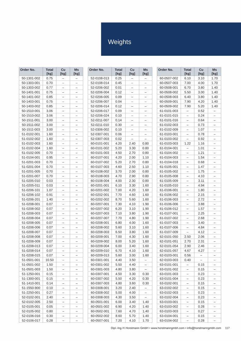
Order No. Total [kg]
Cu[kg]
Ms[kg]
60-0507-002 6.10 3.10 1.7060-0507-003 7.00 4.00 1.7060-0508-001 6.70 3.80 1.4060-0508-002 5.50 3.00 1.4060-0508-003 6.40 3.80 1.4060-0509-001 7.90 4.20 1.4060-0509-002 7.90 5.20 1.4061-0101-003 – 0.52 –61-0101-015 – 0.24 –61-0101-016 – 0.64 –61-0102-003 – 0.73 –61-0102-009 – 1.07 –61-0103-001 – 0.78 –61-0103-002 – 0.92 –61-0103-003 1.22 1.16 –61-0104-001 – 1.01 –61-0104-002 – 1.21 –61-0104-003 – 1.54 –61-0104-018 – 0.68 –61-0105-001 – 1.47 –61-0105-002 – 1.75 –61-0105-008 – 4.10 –61-0105-009 – 3.11 –61-0105-010 – 4.94 –61-0106-001 – 1.80 –61-0106-002 – 2.15 –61-0106-003 – 2.72 –61-0106-006 – 3.88 –61-0106-012 – 1.57 –61-0107-001 – 2.25 –61-0107-002 – 2.68 –61-0107-003 – 3.40 –61-0107-006 – 4.84 –61-0107-009 – 4.12 –62-0101-050 2.50 2.06 –62-0101-051 2.70 2.31 –62-0101-054 2.90 2.46 –62-0101-057 4.67 4.27 –62-0103-001 0.56 – –62-0103-003 0.40 – –63-0101-001 – 0.15 –63-0101-002 – 0.15 –63-0101-003 – 0.23 –63-0101-004 – 0.23 –63-0102-001 – 0.15 –63-0102-002 – 0.15 –63-0102-003 – 0.23 –63-0102-004 – 0.23 –63-0103-001 – 0.15 –63-0103-002 – 0.28 –63-0103-003 – 0.27 –63-0104-001 – 0.15 –63-0104-002 – 0.28 –
Order No. Total [kg]
Cu[kg]
Ms[kg]
52-0108-013 0.25 – –52-0108-014 0.45 – –52-0206-002 0.01 – –52-0206-004 0.12 – –52-0206-005 0.09 – –52-0206-007 0.04 – –52-0206-014 0.12 – –52-0206-017 0.09 – –52-0206-024 0.10 – –52-0211-007 0.14 – –52-0211-010 0.30 – –52-0306-002 0.10 – –52-0307-001 0.06 – –52-0307-003 0.02 – –60-0101-001 4.20 2.40 0.8060-0101-002 5.20 3.30 0.8060-0101-003 4.50 2.70 0.8060-0107-001 4.20 2.00 1.1060-0107-002 5.20 2.70 0.8060-0107-003 4.60 2.50 1.1060-0108-002 3.70 2.00 0.8060-0108-003 4.70 2.90 0.8060-0108-004 4.00 2.30 0.8060-0201-001 6.10 3.30 1.6060-0201-002 7.00 4.20 1.6060-0202-001 7.70 4.60 1.6060-0202-002 8.70 5.60 1.6060-0207-001 7.30 4.10 1.9060-0207-002 6.20 3.10 1.9060-0207-003 7.10 3.80 1.9060-0207-007 7.70 4.80 1.9060-0208-001 6.80 4.00 1.6060-0208-002 5.60 3.10 1.6060-0208-003 6.50 3.80 1.6060-0209-001 7.00 4.30 1.6060-0209-002 8.00 5.20 1.6060-0209-004 6.00 3.40 1.6060-0209-010 6.70 4.10 1.6060-0209-013 5.60 3.00 1.6060-0301-001 4.40 3.50 –60-0301-002 5.50 4.40 –60-0301-003 4.80 3.80 –60-0307-001 4.50 3.30 0.3060-0307-002 5.50 4.20 0.3060-0307-003 4.80 3.60 0.3060-0308-001 3.20 2.40 –60-0308-002 5.00 4.00 –60-0308-003 4.30 3.50 –60-0501-001 6.00 3.40 1.4060-0501-002 6.90 4.20 1.4060-0502-001 7.60 4.70 1.4060-0502-002 8.60 5.70 1.4060-0507-001 7.20 4.10 1.70
Order No. Total [kg]
Cu[kg]
Ms[kg]
50-1301-002 0.75 – –50-1303-001 0.70 – –50-1303-002 0.77 – –50-1401-001 0.75 – –50-1401-002 0.85 – –50-1403-001 0.75 – –50-1403-002 0.85 – –50-1510-001 3.06 – –50-1510-002 3.06 – –50-1511-001 3.00 – –50-1511-002 3.00 – –50-1511-003 3.00 – –51-0102-001 1.60 – –51-0102-002 1.60 – –51-0102-003 1.60 – –51-0102-004 1.60 – –51-0102-005 0.70 – –51-0104-001 0.95 – –51-0201-003 0.70 – –51-0201-004 0.70 – –51-0201-005 0.70 – –51-0201-007 0.70 – –51-0205-010 0.03 – –51-0205-011 0.03 – –51-0206-101 1.07 – –51-0206-102 0.91 – –51-0206-201 1.40 – –51-0208-001 0.07 – –51-0208-002 0.07 – –51-0208-003 0.07 – –51-0208-004 0.07 – –51-0208-005 0.07 – –51-0208-006 0.07 – –51-0208-007 0.07 – –51-0208-008 0.07 – –51-0208-009 0.07 – –51-0208-013 0.07 – –51-0208-014 0.07 – –51-0208-015 0.07 – –51-0501-001 10.50 – –51-0501-002 1.50 – –51-0501-003 1.50 – –51-1250-001 0.15 – –51-1300-001 0.15 – –51-1410-001 0.14 – –51-1550-900 0.10 – –51-2250-001 0.27 – –52-0102-001 2.40 – –52-0102-005 2.50 – –52-0105-001 0.05 – –52-0105-002 0.80 – –52-0106-016 0.30 – –52-0106-017 0.28 – –
117Dipl.-Ing. H. Horstmann GmbH www.horstmanngmbh.com [email protected]
Weights

Order No. Total [kg]
Cu[kg]
Ms[kg]
63-0104-003 – 0.27 –63-0106-001 – 0.19 –63-0106-002 0.23 0.19 –63-0201-001 0.26 0.12 –63-0201-003 0.50 – 0.3463-0201-006 0.94 – 0.2563-0201-007 0.60 – 0.2563-0204-001 0.23 – –63-0205-001 0.14 – 0.1063-0205-002 0.23 – 0.1063-0205-003 0.30 – 0.1063-0206-001 0.34 – 0.2563-0206-002 0.31 – 0.2563-0206-003 0.38 – 0.2564-0101-001 – 0.38 –64-0102-001 0.62 – 0.4264-0102-002 0.76 – 0.5964-0102-003 0.78 – 0.5964-0102-004 0.77 – 0.5964-0102-007 0.90 – 0.4864-0103-001 0.42 – 0.2564-0103-002 0.70 – 0.5264-0103-005 0.64 – 0.2564-0103-006 0.69 – 0.5264-0201-001 0.52 0.36 –64-0201-002 0.95 0.68 –64-0201-003 0.46 0.36 –64-0201-004 0.86 0.68 –64-0201-005 0.55 0.36 –64-0201-006 0.94 0.68 –64-0202-003 0.52 0.15 0.3564-0202-004 0.52 0.15 0.3564-0202-005 0.53 0.15 0.3564-0203-001 0.11 0.06 –64-0203-002 0.15 0.09 –64-0203-003 0.25 0.19 –64-0204-001 0.13 0.07 –64-0204-002 0.17 0.10 –64-0204-003 0.27 0.19 –64-0205-004 – 0.10 –65-0101-001 0.54 – –65-0101-002 0.58 – –65-0101-003 0.68 – –65-0101-004 0.83 – –65-0102-001 1.32 – –65-0102-002 1.65 – –65-0201-001 0.55 – –65-0201-002 0.58 – –65-0201-003 0.68 – –65-0201-004 0.83 – –65-0301-001 1.51 – –65-0301-002 2.22 – –65-0301-003 3.12 – –
Order No. Total [kg]
Cu[kg]
Ms[kg]
65-0301-004 2.50 – –65-0401-001 0.81 – –65-0401-002 0.86 – –65-0401-003 0.99 – –65-0401-004 1.21 – –65-0402-001 1.35 – –65-0402-002 1.45 – –65-0402-003 1.70 – –65-0402-004 1.70 – –65-0403-001 0.90 – –65-0403-003 0.90 – –65-0403-004 1.05 – –65-0502-002 1.70 – –65-0504-001 0.75 – –65-0504-004 0.82 – –66-0101-001 0.54 – –66-0101-002 0.77 – –66-0101-003 0.95 – –66-0201-001 0.50 – –66-0201-002 0.60 – –66-0201-003 0.78 – –67-0101-001 1.10 – –67-0101-002 0.80 – –67-0101-006 0.05 – –67-0101-007 0.03 – –67-0101-014 1.50 – –67-0101-015 0.81 – –67-0301-003 0.20 – –99-0000-124 0.10 – –
118 Dipl.-Ing. H. Horstmann GmbH www.horstmanngmbh.com [email protected]
Weights

Company: Contact partner: Phone:Project:
Network informationOperating voltage VNom: kV Neutral point treatment:
SwitchgearManufacturer: Type: Year of construction: Panel name:
Gas-insulated/solid insulated Air-insulatedC1 capacity: pF or panel type: C1 capacity: pFResistive voltage coupling Set of connectors:
Type of insulator:Insulator has to be supplied cable length: m
Voltage signalSystems solution – Wega
Systems solution – Wega to HR interface
Direct connection – HR interface
Direct connection – capacitive insulator
Wega 1.2 C
Wega 1.2 C vario
Wega 2.2 C
Wega 1.2 C vario HR interface cable
Short-circuit current: µAHR interface: µA
Interface cable for capacitive insulator
Cable length between voltage signal and Sigma / ComPass: m
Directional short-circuit and directional earth fault indicator
Sigma D
Sigma D+
Sigma D++
ComPass B
ComPass B 2.0
ComPass BS 2.0
Cable length between Sigma / ComPass and current signal: m
Current signal
Single-phase current sensor for retrofit on insulated cables
Single-phase current sensor for new installations on bushings
Your comments
119Dipl.-Ing. H. Horstmann GmbH www.horstmanngmbh.com [email protected]
Project PlanningFor directional short-circuit and directional earth fault indicators

Order no.: Inquiry No.:
Short-circuiting cable (a/b/c)
Cable cross section (mm2):
Length a:
Length b:
Length c:
Mounting:
Earthing cable (d)
Cable cross section (mm2):
Length d:
Mounting:
Quantity ordered:
Date of delivery:
120
d
b
d
a c
Dipl.-Ing. H. Horstmann GmbH www.horstmanngmbh.com [email protected]
An order is made exclusively by the terms and conditions of Dipl.-Ing. H. Horstmann GmbH.
Lengths of earthing and short-circuit cables have to fit to the switchgear and the distances between the connection points (min 1.2 times of the distance). If the cables are too long (>1.5 times of the distance) they must be fixed with an insulating cable to prevent damages and injuries in case of a short-circuit.
Company
Contact person
Department
Street
Postcode / Place
Phone / Fax Stamp / Date / Signature
Order / InquiryEarthing and short-circuiting devices
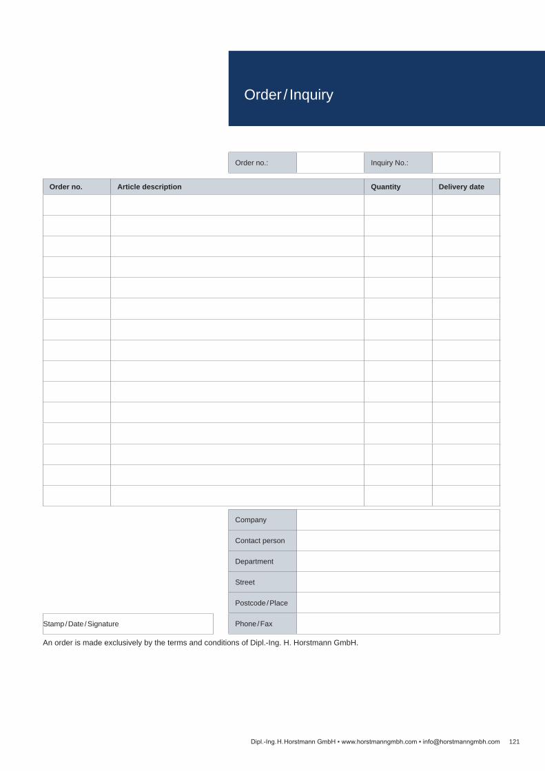
Order no. Article description Quantity Delivery date
Order no.: Inquiry No.:
121Dipl.-Ing. H. Horstmann GmbH www.horstmanngmbh.com [email protected]
An order is made exclusively by the terms and conditions of Dipl.-Ing. H. Horstmann GmbH.
Company
Contact person
Department
Street
Postcode / Place
Phone / FaxStamp / Date / Signature
Order / Inquiry

www.hors tmanngmbh.com
Dipl.-Ing. H. Horstmann GmbHHumboldtstraße 242579 Heiligenhaus
T +49 2056 976-0F +49 2056 [email protected] 20
18
All rights reserved to make technical changes. 101101-0000 / 200 / 03.18