2_2 history nd type of gear
TRANSCRIPT
7/30/2019 2_2 History Nd Type of Gear
http://slidepdf.com/reader/full/22-history-nd-type-of-gear 1/9
Lecture 1
Definition of Gears
1.1 HISTORY OF GEARS
India’ history is the oldest one and some put it as 60,000 years back [1]. Our mythological storiesdate it even before. In all those years people were leaving and were trying to improve their living.
We also know that earlier people were leaving in the caves and the doors of the caves were made
of granite. How were these heavy doors slid or opened? They were slid none other than gear
mechanism as shown in Fig.1.1. However, the documented evidence has been lost due to
destruction by the invaders and improper storing of palm leaf literature. The guru-kula method of
teaching and passing the information mouth to ear procedure and keeping some of the advances
as closed secrets have resulted in poor dissemination of the knowledge. But the knowledge of
gears has gone from India to east through some of the globe trotters from Chine as back as 2600
years BC. They have used the gears then ingeniously in chariots for measuring the speed and
other mechanisms.
Aristotle in the fourth century B.C. wrote as though they were being used very commonly. In the
fifth century AD Leonard a Vinci designed multitude of devices incorporating many kinds of
gears. The industrialization of west made a big impact on gear technology which was a key to the
modern development.
1.2 INTRODUCTION
Gears are toothed members which transmit power / motion between two shafts by meshing
without any slip. Hence, gear drives are also called positive drives. In any pair of gears, the
smaller one is called pinion and larger one is called gear immaterial of which is driving the other.
When pinion is the driver, it results in step down drive in which the output speed decreases and
the torque increases. On the other hand, when the gear is the driver, it results in step up drive in
which the output speed increases and the torque decreases.
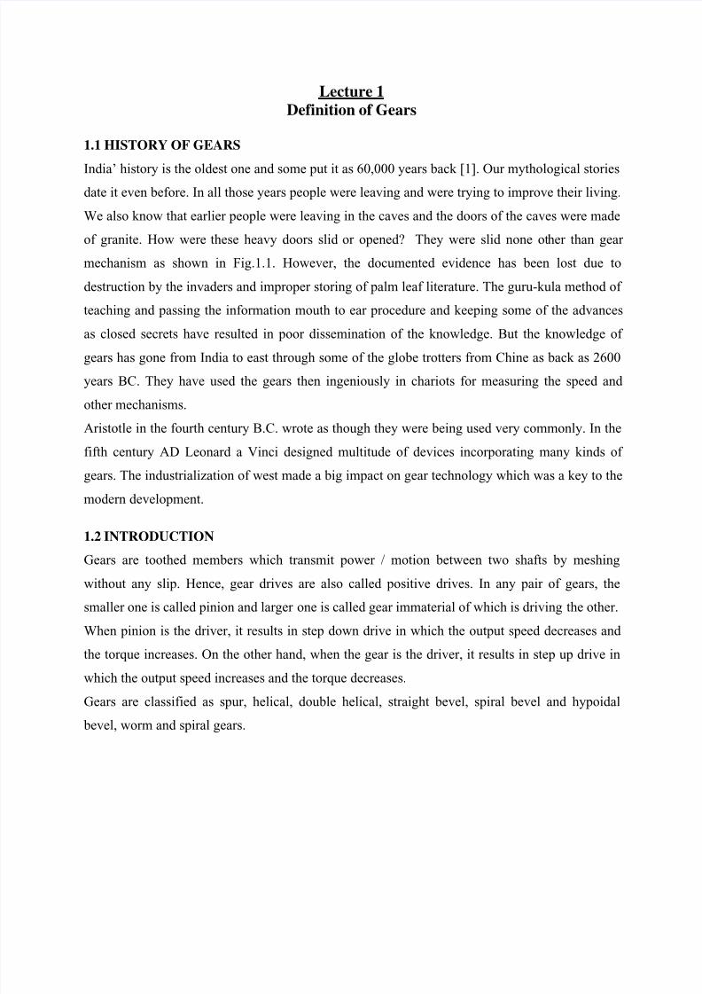
Gears are classified as spur, helical, double helical, straight bevel, spiral bevel and hypoidal
bevel, worm and spiral gears.
7/30/2019 2_2 History Nd Type of Gear
http://slidepdf.com/reader/full/22-history-nd-type-of-gear 2/9
(i) (j)
Fig. 1.2 (a) Spur gear, (b) helicalgear, (c) Double helical gear or
herringbone gear, (d) Internal
gear , (e) Rack and pinion, (f)
Straight bevel gear, (g) Spiral bevel gear, (h) Hypoidal bevel
gear , (i) worm gear and (j) Spiral
gear.
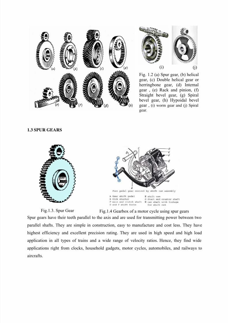
1.3 SPUR GEARS
Fig.1.3. Spur Gear Fig.1.4 Gearbox of a motor cycle using spur gears
Spur gears have their teeth parallel to the axis and are used for transmitting power between two
parallel shafts. They are simple in construction, easy to manufacture and cost less. They havehighest efficiency and excellent precision rating. They are used in high speed and high load
application in all types of trains and a wide range of velocity ratios. Hence, they find wide
applications right from clocks, household gadgets, motor cycles, automobiles, and railways to
aircrafts.
7/30/2019 2_2 History Nd Type of Gear
http://slidepdf.com/reader/full/22-history-nd-type-of-gear 3/9
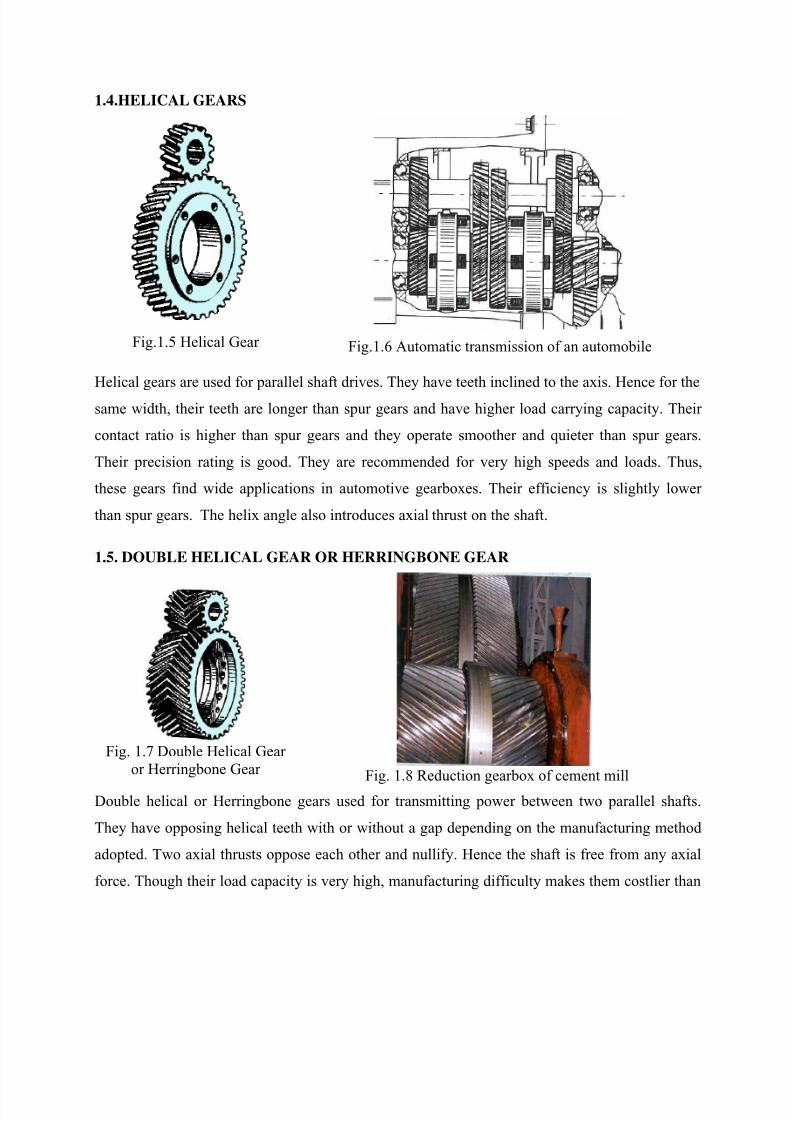
1.4.HELICAL GEARS
Fig.1.5 Helical Gear Fig.1.6 Automatic transmission of an automobile
Helical gears are used for parallel shaft drives. They have teeth inclined to the axis. Hence for the
same width, their teeth are longer than spur gears and have higher load carrying capacity. Their
contact ratio is higher than spur gears and they operate smoother and quieter than spur gears.
Their precision rating is good. They are recommended for very high speeds and loads. Thus,
these gears find wide applications in automotive gearboxes. Their efficiency is slightly lower
than spur gears. The helix angle also introduces axial thrust on the shaft.
1.5. DOUBLE HELICAL GEAR OR HERRINGBONE GEAR
Fig. 1.7 Double Helical Gear
or Herringbone Gear Fig. 1.8 Reduction gearbox of cement mill
Double helical or Herringbone gears used for transmitting power between two parallel shafts.
They have opposing helical teeth with or without a gap depending on the manufacturing method
adopted. Two axial thrusts oppose each other and nullify. Hence the shaft is free from any axial
force. Though their load capacity is very high, manufacturing difficulty makes them costlier than

7/30/2019 2_2 History Nd Type of Gear
http://slidepdf.com/reader/full/22-history-nd-type-of-gear 4/9
single helical gear. Their applications are limited to high capacity reduction drives like that of
cement mills and crushers.
1.6. INTERNAL GEAR
Fig.1.9.Internal Gear
A. flywheel b. intermediate shaft
B. torque divider c. output brake
C. torque converter d. divider brake
D. rear transmission e. rear transmission brakesa. input shaft f. free wheel
Fig. 1.10 Diwabus transmission (Voith)
Internal gears are used for transmitting power between two parallel shafts. In these gears, annular
wheels are having teeth on the inner periphery. This makes the drive very compact. In these
drives, the meshing pinion and annular gear will be running in the same direction. Their precision
rating is fair. They are useful for high load and high speed application with high reduction ratio.
Applications of these gears can be seen in planetary gear drives of automobile automatic
transmissions, reduction gearboxes of cement mills, step-up drives of wind mills.
They are not recommended for precision meshes because of design, fabrication, and inspection
limitations. They should only be used when internal feature is necessary. However, today
precision machining capability has led to their usage even in position devices like antenna drives.
1.5 Rack and Pinion
Fig 1.9. Rack and Pinion Fig. 1.10 Rack and pinion arrangement for lathe carriage
movement
7/30/2019 2_2 History Nd Type of Gear
http://slidepdf.com/reader/full/22-history-nd-type-of-gear 5/9
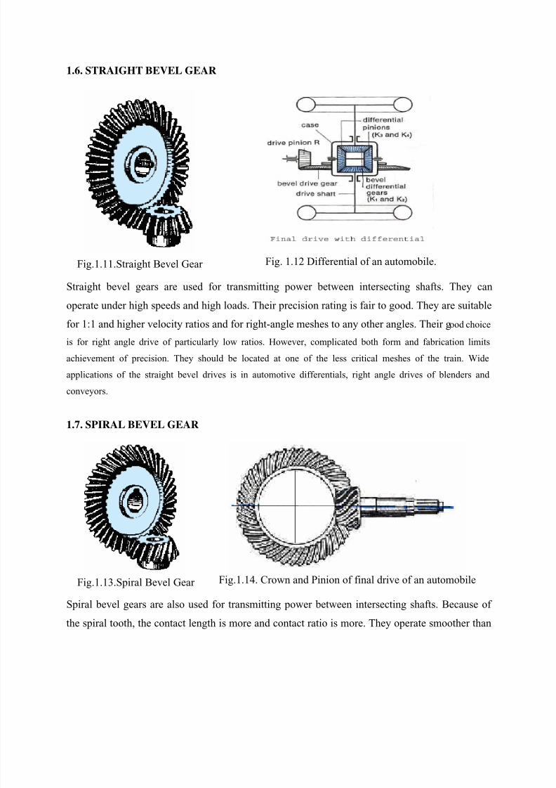
1.6. STRAIGHT BEVEL GEAR
Fig.1.11.Straight Bevel Gear Fig. 1.12 Differential of an automobile.
Straight bevel gears are used for transmitting power between intersecting shafts. They can
operate under high speeds and high loads. Their precision rating is fair to good. They are suitable
for 1:1 and higher velocity ratios and for right-angle meshes to any other angles. Their good choice
is for right angle drive of particularly low ratios. However, complicated both form and fabrication limits
achievement of precision. They should be located at one of the less critical meshes of the train. Wide
applications of the straight bevel drives is in automotive differentials, right angle drives of blenders and
conveyors.
1.7. SPIRAL BEVEL GEAR
Fig.1.13.Spiral Bevel Gear Fig.1.14. Crown and Pinion of final drive of an automobile
Spiral bevel gears are also used for transmitting power between intersecting shafts. Because of
the spiral tooth, the contact length is more and contact ratio is more. They operate smoother than
7/30/2019 2_2 History Nd Type of Gear
http://slidepdf.com/reader/full/22-history-nd-type-of-gear 6/9
straight bevel gears and have higher load capacity. But, their efficiency is slightly lower than
straight bevel gear.
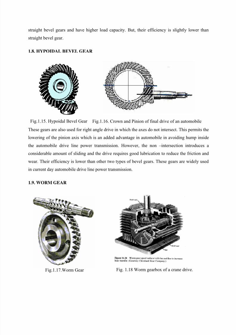
1.8. HYPOIDAL BEVEL GEAR
Fig.1.15. Hypoidal Bevel Gear Fig.1.16. Crown and Pinion of final drive of an automobile
These gears are also used for right angle drive in which the axes do not intersect. This permits the
lowering of the pinion axis which is an added advantage in automobile in avoiding hump inside
the automobile drive line power transmission. However, the non –intersection introduces a
considerable amount of sliding and the drive requires good lubrication to reduce the friction and
wear. Their efficiency is lower than other two types of bevel gears. These gears are widely used
in current day automobile drive line power transmission.
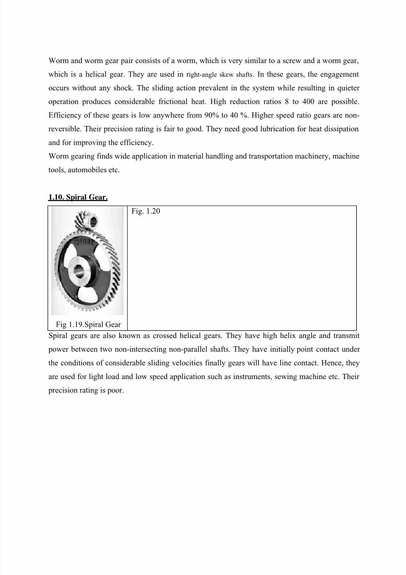
1.9. WORM GEAR
Fig.1.17.Worm Gear Fig. 1.18 Worm gearbox of a crane drive.
7/30/2019 2_2 History Nd Type of Gear
http://slidepdf.com/reader/full/22-history-nd-type-of-gear 7/9
Worm and worm gear pair consists of a worm, which is very similar to a screw and a worm gear,
which is a helical gear. They are used in r ight-angle skew shafts. In these gears, the engagement
occurs without any shock. The sliding action prevalent in the system while resulting in quieter
operation produces considerable frictional heat. High reduction ratios 8 to 400 are possible.
Efficiency of these gears is low anywhere from 90% to 40 %. Higher speed ratio gears are non-
reversible. Their precision rating is fair to good. They need good lubrication for heat dissipation
and for improving the efficiency.
Worm gearing finds wide application in material handling and transportation machinery, machine
tools, automobiles etc.
1.10. Spiral Gear.
Fig 1.19.Spiral Gear
Fig. 1.20
Spiral gears are also known as crossed helical gears. They have high helix angle and transmit
power between two non-intersecting non-parallel shafts. They have initially point contact under
the conditions of considerable sliding velocities finally gears will have line contact. Hence, they
are used for light load and low speed application such as instruments, sewing machine etc. Their
precision rating is poor.
7/30/2019 2_2 History Nd Type of Gear
http://slidepdf.com/reader/full/22-history-nd-type-of-gear 8/9
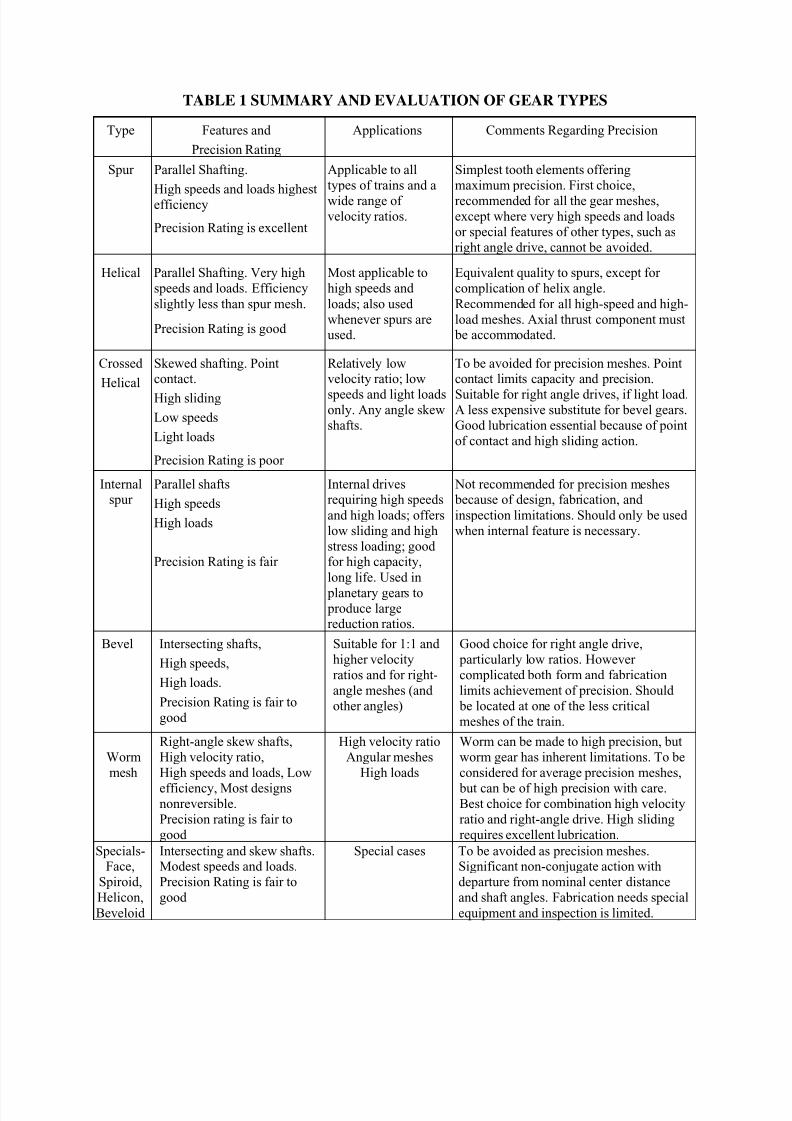
TABLE 1 SUMMARY AND EVALUATION OF GEAR TYPES
Type Features and
Precision Rating
Applications Comments Regarding Precision
Spur Parallel Shafting.
High speeds and loads highest
efficiency
Precision Rating is excellent
Applicable to all
types of trains and a
wide range of velocity ratios.
Simplest tooth elements offering
maximum precision. First choice,
recommended for all the gear meshes,except where very high speeds and loads
or special features of other types, such as
right angle drive, cannot be avoided.
Helical Parallel Shafting. Very high
speeds and loads. Efficiency
slightly less than spur mesh.
Precision Rating is good
Most applicable to
high speeds and
loads; also used
whenever spurs areused.
Equivalent quality to spurs, except for
complication of helix angle.
Recommended for all high-speed and high-
load meshes. Axial thrust component must be accommodated.
Crossed
Helical
Skewed shafting. Pointcontact.
High sliding
Low speeds
Light loads
Precision Rating is poor
Relatively lowvelocity ratio; low
speeds and light loadsonly. Any angle skew
shafts.
To be avoided for precision meshes. Pointcontact limits capacity and precision.
Suitable for right angle drives, if light load.A less expensive substitute for bevel gears.
Good lubrication essential because of point
of contact and high sliding action.
Internalspur
Parallel shafts
High speeds
High loads
Precision Rating is fair
Internal drivesrequiring high speeds
and high loads; offers
low sliding and high
stress loading; good for high capacity,
long life. Used in
planetary gears to produce largereduction ratios.
Not recommended for precision meshes because of design, fabrication, and
inspection limitations. Should only be used
when internal feature is necessary.
Bevel Intersecting shafts,
High speeds,
High loads.
Precision Rating is fair to
good
Suitable for 1:1 and
higher velocity
ratios and for right-
angle meshes (and
other angles)
Good choice for right angle drive,
particularly low ratios. However
complicated both form and fabrication
limits achievement of precision. Should
be located at one of the less critical
meshes of the train.
Worm
mesh
Right-angle skew shafts,
High velocity ratio,
High speeds and loads, Low
efficiency, Most designsnonreversible.
Precision rating is fair to
good
High velocity ratio
Angular meshes
High loads
Worm can be made to high precision, but
worm gear has inherent limitations. To be
considered for average precision meshes,
but can be of high precision with care.Best choice for combination high velocity
ratio and right-angle drive. High sliding
requires excellent lubrication.
Specials-Face,
Spiroid,
Helicon,
Beveloid
Intersecting and skew shafts.Modest speeds and loads.
Precision Rating is fair to
good
Special cases To be avoided as precision meshes.Significant non-conjugate action with
departure from nominal center distance
and shaft angles. Fabrication needs special
equipment and inspection is limited.

7/30/2019 2_2 History Nd Type of Gear
http://slidepdf.com/reader/full/22-history-nd-type-of-gear 9/9