3 anni di garanzia yea r s t r e - iteu.com.ua · 3 anni di garanzia compatibile con remote drive 2...
TRANSCRIPT

3 anni di garanzia
Compatibile con Remote Drive
2 anni di garanzia
R
EMOTE
D R I VE
R
E TE
D R I VE
3WAR
RANTY
Y
E A R
S
2WAR
RANTY
Y
E A R
S
LAB. RIC. AUT. MIUR(G.U. 183 DEL 6/7/83)

ELETTRONICASANTERNO
CONTENTSINDICE
* I dati tecnici di questo catalogo possono essere variati senza alcun preavviso* The technical data shown on this catalogue may be changed without prior notice
Indice/Contents 3
Orion Drive 4
Vega Drive 6
Sinus K 8
Sinus PENTA 10
Sinus BOX K and PENTA 12
Sinus CABINET K and PENTA 13
Sinus K and PENTA – Scelta del prodotto / Product selection 14
Sinus K and PENTA– Accessori/Accessories 25
Sinus K Software Lift 28
EStart SFTS 30
ASAC 32
ASA 34
ASA-MV 38
DCREG2-DCREG4 42
CU400 45
Remote Drive 46
DBF 200T 48
DBU 50
ESB 52
ATA-MA 54
MV 58
Accessori/Accessories 60
Centri Assistenza/Service Centers 64

ORIO
N D
RIV
E INVERTER A CONTROLLO VETTORIALE SENSORLESS O V/F
SENSORLESS VECTOR CONTROL OR V/F INVERTER
1 year warranty
200 - 230Vac single phasepower supply
Full digital
Power range 0,4 - 3kW
Full compatibility withteleservice software “REMOTEDRIVE” on internet
1 anno di garanzia
Alimentazione 200 - 230Vacmonofase
Full digital
Potenze da 0,4 a 3kW
Compatibile con software diteleassistenza, “REMOTE
DRIVE” via internet
R
EMOTE
D R I VE
R
E TE
D R I VE

STANDARD FEATURES
200-230Vac single phase power supplyPower range 0,4~3kW2 control modes: V/F and Sensorless Vector ControlBuilt-in potentiometerStart/stop keypadsEnclosure IP20Overload capacity 150% per 1 min. 200% for 0,5 sec.Maximum output frequency 400HzMotor auto-tuning for optimum performanceAnti-stalling and antitrip algorithmAdjustable carrier 1-15kHzAutomatic and manual torque boostJOG functionSpeed searchPID function"S" ramps8 speed sets3 frequency jumps (skip)5 NPN PNP programmable digital inputs2 analog inputs 0-10Vdc and 4-20mA1 multi-function open collector output1 Multi-function relay output1 analog multi-function output 0-10VdcINTEGRATED EMC INPUT FILTERS EN 61800-3 2nd edition FIRSTENVIRONMENT C1 Category, EN55011 gr.1 cl. B for industrial and domesticusers, EN50081-1, -2, EN50082-1, -2, EN61800-3-A11
OPTIONS
Output ferrite ring filtersAnalog converter V/I (0-10/4-20mA)Relay for open collector output“Remote Drive” softwareConverter for MODBUS/Profibus DP-CanBus-Device Net etc.RS 485/232 converter
CARATTERISTICHE TECNICHE
Alimentazione 200-230Vac, monofasePotenze 0,4~3kW
2 tecnologie di controllo: V/F e Controllo Vettoriale SensorlessPotenziometro incorporato
Pulsanti marcia e arrestoGrado di protezione IP20
Sovraccarico 150% per 1 min. 200% per 0,5 sec.Frequenza massima uscita 400Hz
Funzione auto-tuning per un ottimo controllo del motoreAlgoritmo antistallo e antitrip
Carrier regolabile 1-15kHzBoost di coppia automatico e manuale
Funzione JOGSpeed searchFunzione PIDRampe ad S
8 set di velocità3 salti di frequenza
5 ingressi digitali programmabili NPN PNP2 ingressi analogici 0-10Vdc e 4-20mA
1 uscita open collector multifunzione1 uscita a relè multifunzione
1 uscita analogica multifunzione 0-10VdcFILTRO D’INGRESSO INTEGRATO EN 61800-3 edizione 2 PRIMO AMBIENTE
Categoria C1, EN55011 gr.1 cl. B per utenze industriali e domestiche,EN50081-1, -2, EN50082-1, -2, EN61800-3-A11
OPZIONI
Filtro toroidale di uscitaConvertitore analogico V/I (0-10/4-20mA)
Relè per uscita open collectorSoftware “Remote Drive”
Convertitore MODBUS/Profibus DP-CanBus-Device Net ecc.Convertitore RS 485/232
ELETTRONICASANTERNO
5
Informazioni tecniche più dettagliate sono disponibili su www.elettronicasanterno.it /More technical information available at www.elettronicasanterno.it
Motore Applicabile 200-230Vac Dimensioni Pesi/Weight Pesi/WeightMotor power 1 phase Dimensions senza filtro/without filter con filtro/with filter
kW CV In (WxHxD) mm (Kg.) (Kg.)ORION DRIVE 2S0001XBK2 0,4 0,5 2,5 79x143x143 0,9 1,2ORION DRIVE 2S0002XBK2 0,75-1,1 1-1,5 5 79x143x143 0,9 1,2ORION DRIVE 2S0003XBK2 1,5-1,8 2-2,5 8 156x143x143 1,8 2,3ORION DRIVE 2S0005XBK2 2,2-3 3-4 12 156x143x143 1,8 2,4
Tipo Type

VEG
A D
RIV
E INVERTER A CONTROLLO SPACE VECTOR
SPACE VECTOR CONTROL INVERTER
1 year warranty
Full digital
200 - 460 Vac power supply
Power range 0,37 - 4,5kW
Full compatibility withteleservice software “REMOTEDRIVE” on internet
R
EMOTE
D R I VE
R
E TE
D R I VE
1 anno di garanzia
Full digital
Tensione d’alimentazione200 - 460Vac
Gamma di potenzeda 0,37 a 4,5kW
Compatibile con software diteleassistenza, “REMOTE
DRIVE” via internet

TECHNICAL FEATURES
Power ranges:0.37~1.8kW 200-230Vac, 1phase0.37~4.5kW 200-230Vac, 3phase0.37~4.0kW 380-460Vac, 3phase
IP20 enclosureIGBT InverterSPACE-VECTOR ControlSerial port RS 485 with protocol MODBUS RTURemotable smart keyboardOverload 150% of In for 60 sec.Overload 200% for short time spanMaximum torque 180% CnMaximum output frequency 400HzAnti-stalling and antitrip algorithm8 speed sets3 frequency jumps (skip)8 NPN PNP programmable digital inputs2 analog inputs 0-10Vdc and 4-20mA1 programmable open collector output1 relay alarm output1 analog output 0-10VdcAdjustable carrier 1-10kHzIncorporated braking unitAutomatic and manual torque boostSpeed searchPID function"S" rampsEMC compliant with EN 61800-3, industrial power utility, SECOND ENVIRONMENT
OPTIONS
Kit remote keyboard operation (3 metres)EMC foot print filters EN 55011 Cl. A and B, public utility, FIRST ENVIRONMENT.Braking resistorsAnalog converter V/I (0-10/4-20mA)Relay for open collector output“Remote Drive” softwareConverter for MODBUS/Profibus DP-CanBus-Device Net etc.RS 485/232 converter
CARATTERISTICHE TECNICHE
Gamma di potenze:0.37~1.8kW 200-230Vac, 1phase0.37~4.5kW 200-230Vac, 3phase0.37~4.0kW 380-460Vac, 3phase
Grado di protezione IP20Inverter ad IGBT
Controllo SPACE-VECTORPorta seriale RS 485 con protocollo MODBUS RTU
Tastiera remotabile intelligenteSovraccarico 150% della In per 60 sec.
Sovraccarico 200% per breve durataCoppia massima 180% Cn
Frequenza massima uscita 400HzAlgoritmo antistallo e antitrip
8 set di velocità3 salti di frequenza
8 ingressi digitali programmabili NPN PNP2 ingressi analogici 0-10Vdc e 4-20mA
1 uscita open collector multifunzione1 uscita a relè d’allarme
1 uscita analogica 0-10VdcCarrier regolabile 1-10kHz
Modulo di frenatura integratoBoost di coppia automatico e manuale
Speed searchFunzione PIDRampe ad S
EMC conforme EN 61800-3, rete industriale, SECONDO AMBIENTE
OPZIONI
Kit remotizzazione tastiera a distanza (3 metri)Filtri EMC foot print EN 55011 Cl. A e B, rete pubblica, PRIMO AMBIENTE
Resistenze di frenaturaConvertitore analogico V/I (0-10/4-20mA)
Relè per uscita open collectorSoftware “Remote Drive”
Convertitore MODBUS/Profibus DP-CanBus-Device Net ecc.Convertitore RS 485/232
ELETTRONICASANTERNO
7
Informazioni tecniche più dettagliate sono disponibili su www.elettronicasanterno.it /More technical information available at www.elettronicasanterno.it
Modello/Model
LxPxA/WxDxH(mm)
2S0001BIK2T0001BIK2T0002BIK
100x130,9x128
2S0002BIK2T0003BIK4T0001BIK4T0002BIK4T0003BIK
130x150,9x128
2S0003BIK2T0005BIK2T0007BIK4T0005BIK4T0007BIK
150x155x128
(Kg)
1,2
1,8
2,2
Vega Drive
Dimensioni e Pesi/Dimensions and WeightMotore Applicabile/Motor power
0,75-0,9 1,1 4T0002BIK1,5 2S0002BIK 2T0002BIK2 4T0003BIK2,5 2S0003BIK 2T0003BIK3-4 2T0005BIK
6
kW0,750,37-0,55
0,75-1,11,51,5-1,82,2-3
4,5
2S0001BIK 2T0001BIK 4T0001BIK
200-230Vac1 phase
200-230Vac3 phase
380-460Vac3 phase
CV
32T0007BIK
4T0005BIK
5,5 4T0007BIK
2,2
4
Amodel3
5
8
3
5
8
17
12
A A1,52,5
4
9
6
model model

SIN
US
K INVERTER VETTORIALE SENSORLESS A CONTROLLO DI COPPIA O V/F
SENSORLESS VECTOR TORQUE CONTROL OR V/F INVERTER
3 years warranty
Wide power supply voltagerange, 200Vac - 690Vac
Input frequency 50 - 60Hz
Power range 1,3 - 1200kW
Enclosure IP00, IP20, IP54
Full digital
Full compatibility withteleservice software “REMOTEDRIVE” on internet
3 anni di garanzia
Ampia gamma di tensionid'alimentazione da200Vca a 690Vca
Frequenza ingresso50 - 60Hz
Potenza da 1,3 - 1200kW
Contenitore IP00, IP20, IP54
Full digital
Compatibile con software diteleassistenza,
“REMOTE DRIVE” via internet
R
EMOTE
D R I VE
R
E TE
D R I VE
3WAR
RANTY
Y
E A R
S

TECHNICAL FEATURES
One product, 2 functions:- For general applications, vector modulation IFD software- For heavy torque performance, sensorless vector control VTC softwareIntegrated filters on the full range in compliance with EN61800-3 2nd ed.about RFI emission limitsInput contactor not necessary (doc. IEC 22G/109/NP draft of IEC61800-5Safety requirements)Compact dimensionsIntelligent cooling systemIntegrated braking chopper up to S30Lower motor noise with carrier frequency up to 16kHz(IFD and LIFT software)Motor PTC thermal probe controlEasy commissioning with preset parameters for most common applicationsControl panel with 8 keys and large display (optional)Regulation of output frequency from 0 to 800Hz (150Hz for VTC software)In case of power failure, total control of the motor,down to 0 RPMMaster-slave function for the operation of several motors connected to the samedrive shaft.Automatic calibration for motor parameters’ recognition200% max torquePID regulatorSkip frequencyIntegrated digital potentiometerIntegrated multifunctional testerTrip LogIntegrated thermal protection of motor.Automatic DC brakingProgrammable multiple acceleration and deceleration rampsFeedback from tachometric dynamo or encoder8 programmable inputs4 programmable analog inputs 0-10Vdc, 0(4)-20mA2 programmable relays output1 open collector outputAuxiliary voltages 24Vdc, 10Vdc2 programmable analog ouputs 0-10Vdc, 0(4)-20mASerial communication RS485 with MODBUS RTU protocol
SPECIAL EXECUTIONS
12 impulse bridgeStarting from the S50 size, it is possible to supply the drive on 12 impulsebridge configuration (S50 and S60, in this case, become S65; S65 becomesS70 and S70 remains the same)
CARATTERISTICHE TECNICHE
Unico prodotto, 2 funzioni:- Software IFD a modulazione vettoriale per applicazioni generiche
- Software VTC vettoriale sensorless per elevate prestazioni di coppiaFiltri integrati su tutta la gamma in conformità alla norma EN61800-3 ed.
2 sui limiti d’emissioneNon necessita di contattore di linea (documento di lavoro IEC 22G/109/NP
bozza della norma IEC61800-5 Safety requirements)Dimensioni compatte
Sistema di raffreddamento intelligenteModulo di frenatura integrato fino a S30
Maggiore silenziosità motore con frequenza di carrier fino a 16kHz(software IFD e LIFT)
Controllo sonda termica PTC motoreMessa in servizio semplice con parametri preimpostati per le applicazioni più frequenti
Pannello di controllo a 8 tasti e ampio display (opzionale)Regolazione della frequenza di uscita da 0 a 800Hz (150Hz per software VTC)Fermata controllata del motore fino alla velocità zero in caso di mancanza
della rete di alimentazioneFunzione master-slave per il funzionamento di più motori collegati sullo stesso
albero meccanicoTaratura automatica per il riconoscimento delle caratteristiche motore
Coppia massima 200%Funzione PID
Salti di frequenzaPotenziometro digitale integrato
Tester multifunzione integratoStorico Allarmi
Protezione termica motori integrataFrenatura in corrente continua automatica
Multirampe di accelerazione e decelerazione programmabiliRetroazione da dinamo tachimetrica o encoder
8 ingressi digitali programmabili4 ingressi analogici 0-10Vdc, 0(4)-20mA
2 uscite configurabili a relè con contatti in scambio1 uscita open collector
Tensioni ausiliarie 24Vdc, 10Vdc2 uscite analogiche configurabili 0-10Vdc, 0(4)-20mA
Comunicazione seriale RS485 con protocollo MODBUS RTU
ESECUZIONI SPECIALI
Esecuzione dodecafaseDalla grandezza S50 è possibile fornire il drive in configurazione dodecafase
(S50 e S60, in questo caso, diventano S65; S65 diventa S70 eS70 resta invariato)
ELETTRONICASANTERNO
9
Informazioni tecniche più dettagliate sono disponibili su www.elettronicasanterno.it /More technical information available at www.elettronicasanterno.it

SIN
US
PEN
TA
INVERTER UNIVERSALE 5 FUNZIONI, FINO A 2000kW
3 years warranty
Wide power supply voltagerange, 200Vac÷690Vac
DC power supply range280÷970Vdc
Input frequency 50 - 60Hz
Power range 1,3 - 2000kW
Enclosure IP00, IP20, IP54
Available in stand-alone andcabinet solutions
Full compatibility withteleservice software, "REMOTEDRIVE" on internet
R
EMOTE
D R I VE
R
E TE
D R I VE
3 anni di garanzia
Ampia gamma d'alimentazione200Vca÷690Vca
Alimentazione DC 280÷970Vdc
Frequenza ingresso 50 - 60Hz
Potenza da 1,3 - 2000kW
Contenitore IP00, IP20, IP54
Disponibile in soluzionestand-alone e cabinet
Compatibile consoftware di teleassistenza,
"REMOTE DRIVE" via internet
5 funzioni integrate:- IFD (Inverter Frequency Drive): funzione IFD a modulazione vettoriale per applicazioni generiche (curva V/F)- VTC (Vector Torque Control): funzione VTC vettoriale sensorless per applicazioni ad elevate prestazioni di coppia (controllo diretto di coppia)- FOC (Field Oriented Control): funzione vettoriale con encoder per applicazioni ad elevata precisione di coppia e ampio campo di velocità- SYN (Synchronous): funzione vettoriale per applicazioni con motori sincroni brushless con magneti permanenti caratterizzate da elevata precisione di coppia unita ad elevata efficienza energetica- RGN (Regenerative): funzione Alimentatore AC/DC Rigenerativo Sinusoidale cosfi=1 per l'alimentazione diretta di una serie di azionamentiLe applicazioni d’automazione integrate nella linea SINUS PENTA rappresentano una soluzione semplice edeconomica nella gestione di SERVODIAMETRI, impianti MULTIPOMPA, motorizzazioni in ASSE ELETTRICO eMULTIPOSIZIONATORI.
5 integrated functions:- IFD (Inverter Frequency Drive): vector modulation function for generic applications (V/F pattern)- VTC (Vector Torque Control): sensorless vector function for high torque performance applications (direct torque control)- FOC (Field Oriented Control): vector function with encoder for high torque precision and wide speed range- SYN (Synchronous): vector function for brushless asynchronous motors with permanent magnets characterized by high torque precision joined to high energy efficiency level- RGN (Regenerative): sinusoidal cosfi=1, AC/DC supplier function for direct supply of a series of drivesAutomation applications enclosed into the inverters of the SINUS PENTA series allow a simple and inexpensivemanagement of SERVODIAMETERS, MULTIPUMP systems, ELECTRICAL AXIS motor systems and MULTIPOSITIONERS.
5-FUNCTION, ALL-PURPOSE INVERTER, UP TO 2000kW
3WAR
RANTY
Y
E A R
S

11
TECHNICAL SPECIFICATIONS
One product, 5 functions:- vectorial modulation IFD functionality for general-purpose applications (V/f pattern)- sensorless vectorial VTC functionality for high torque- demanding applications(direct torque control)- vectorial FOC functionality with an encoder for accurate torque requirementsand a wide speed range- vectorial SYN functionality for applications with brushless, synchronousmotors with permanent magnets, requiring very accurate torque values andexcellent energy performances- RGN functionality for the inverter application as an AC/DC converter forthe DC supply of multiple drivesPC-compiled software for the programming of more than 20 applicationfunctions (in that case, an optional board is required)Integrated filters on the full range in compliance with EN61800-3 2nd ed.about RFI emission limitsInput contactor not necessary (doc. IEC 22G/109/NP draft of IEC61800-5Safety requirements)Compact dimensionsIntelligent cooling systemIntegrated braking chopper up to S30Operating parameters saved to remotable module and possibility of parametertransfer to multiple invertersLower motor noise with carrier frequency up to 16kHz(IFD and LIFT software)Motor PTC thermal probe controlEasy commissioning with preset parameters for the most common applicationsControl panel with 12 keys and large back-lit LCDRegulation of output frequency from 0 to 1000HzIn case of power failure, total control of the motor,down to 0 RPMMaster-slave function for the operation of several motors connected to thesame drive shaft (VTC and FOC)Automatic calibration for motor parameters’ acknowledgement200% max torquePID regulatorSkip frequencyIntegrated digital potentiometerIntegrated multifunctional testerTrip LogIntegrated motor thermal protectionAutomatic DC brakingProgrammable multiple acceleration and deceleration rampsFeedback from tacho generator or encoder8 programmable inputs3 programmable analog inputs 0-10Vdc, 0(4)-20mA2 programmable output relays with exchange contact1 open collector output1 digital Push-Pull outputAuxiliary input frequency 5,000-65,000 HzAuxiliary output frequency 5,000-65,000 Hz3 programmable analog outputs 0-10Vdc, 0(4)-20mAAuxiliary voltage 24Vdc, 10VdcSerial communication RS485 with MODBUS RTU protocol up to38.400 BaudProgrammable S ramps
SPECIAL EXECUTIONS
12 impulse bridgeStarting from the S50 size, it is possible to supply the drive on 12 impulsebridge configuration (S50 and S60, in this case, become S65; S65 becomesS70 and S70, S75, S80 remains the sames)
* -Available starting from the 2nd semester 2005-
ELETTRONICASANTERNOInformazioni tecniche più dettagliate sono disponibili su www.elettronicasanterno.it /More technical information available at www.elettronicasanterno.it
CARATTERISTICHE TECNICHE
Unico prodotto, 5 funzioni:- funzione IFD a modulazione vettoriale per applicazioni generiche (curva V/f)- funzione VTC vettoriale sensorless per applicazioni ad elevate prestazioni
di coppia (controllo diretto di coppia)- funzione FOC vettoriale con encoder per applicazioni ad elevata precisione
di coppia e ampio campo di velocità- funzione SYN vettoriale per applicazioni con motori sincroni brushless conmagneti permanenti caratterizzate da elevata precisione di coppia unita ad
elevata efficienza energetica- funzione RGN per applicazione come convertitore AC/DC per l'alimentazione
in continua di una serie di azionamentiSoftware compilati su PC per la programmazione di oltre 20 funzioni applicative
(richiede scheda opzionale)Filtri integrati su tutta la gamma in conformità alla norma EN61800-3 ed.
2 sui limiti di emissioneNon necessita di contattore di linea (documento di lavoro IEC 22G/109/NP
bozza della norma IEC61800-5 Safety requirements)Dimensioni compatte
Sistema di raffreddamento intelligenteModulo di frenatura integrato fino a S30
Salvataggio dei parametri di funzionamento sul modulo remotabile e possibilitàdi trasferimento a più inverters.
Maggiore silenziosità motore con frequenza di carrier fino a 16kHz(controllo motore IFD e LIFT)
Controllo sonda termica PTC motoreMessa in servizio semplice con parametri preimpostati per le applicazioni più frequenti
Pannello di controllo a 12 tasti e ampio display retroilluminatoRegolazione della frequenza di uscita da 0 a 1000Hz
Fermata controllata del motore fino alla velocità zero in caso di mancanzadella rete di alimentazione
Funzione master-slave per il funzionamento di più motori collegati sullo stessoalbero meccanico (per controllo VTC e FOC)
Taratura automatica per il riconoscimento delle caratteristiche motoreCoppia massima 200%
Funzione PIDSalti di frequenza
Potenziometro digitale integratoTester multifunzione integrato
Storico AllarmiProtezione termica motori integrata
Frenatura in corrente continua automaticaMultirampe di accelerazione e decelerazione programmabili
Retroazione da dinamo tachimetrica o encoder8 ingressi digitali programmabili
3 ingressi analogici 0-10Vdc, 0(4)-20mA2 uscite configurabili a rele` con contatti in scambio
1 uscita digitale open collector1 uscita digitale Push Pull
Ingresso in frequenza 5000-65000 HzUscita in frequenza 5000-65000 Hz
3 uscite analogiche configurabili 0-10Vdc, 0(4)-20mATensioni ausiliarie 24Vdc isolata, 10Vdc
Comunicazione seriale RS485 con protocollo MODBUS RTU con velocità finoa 38.400 Baud
Rampe ad S programmabili
ESECUZIONI SPECIALI
Esecuzione dodecafaseDalla grandezza S50 è possibile fornire il drive in configurazione dodecafase
(S50 e S60, in questo caso, diventano S65; S65 diventa S70 eS70, S75, S80 restano invariati)
* -Disponibili dal 2° semestre 2005-

SIN
US
BO
X LA SOLUZIONE IN CASSETTA IP54
INVERTER IN BOX IP54
Gli inverter della linea Sinus K e PENTA possono essere montati in cassetta con grado di protezione fino a IP54.Possono essere personalizzati con un serie di opzioni a scelta.
Sinus K and PENTA line inverters can be provided in box up to IP54 protection degree.A custom made solution is given by a choice of options.
K a
nd P
ENTA
R
EMOTE
D R I VE
R
E TE
D R I VE
3 years warranty
Wide power supply voltagerange, 200Vac - 500Vac
Input frequency 50 - 60Hz
Power range 1,3 - 90kW
Full compatibility withteleservice software “REMOTEDRIVE” on internet
3 anni di garanzia
Ampia gamma di tensionid'alimentazione da200Vca a 500Vca
Frequenza ingresso 50 - 60Hz
Potenza da 1,3 - 90kW
Compatibile con software diteleassistenza, “REMOTE
DRIVE” via internet
3WAR
RANTY
Y
E A R
S
OPTIONS
Input three pole switch circuit breakerAC1 input three pole contactorFront operation board by key selector LOCAL/REMOTEcommand and EMERGENCY push-bottonInput chokesMotor side output chokesPower supply circuit for servoventilationInternal resistor against condesationSupplementary terminal board for input and output cablesFront box lighted display with keyboard
OPZIONI
Interruttore magnetico di linea con bobina di sgancioContattore di linea in AC1
Comando frontale mediante selettore a chiave per comandoLOCALE/REMOTO e pulsante d’EMERGENZA
Impedenza d’ingresso lineaImpedenza d’uscita lato motore
Circuito servoventilazione motoreScaldiglia anticondensa
Morsettiera supplementare per cavi ingresso/uscitaDisplay illuminato con tastiera fronte cassetta
LA SOLUZIONE IN QUADRO
INVERTER IN CABINET
3WAR
RANTY
Y
E A R
S
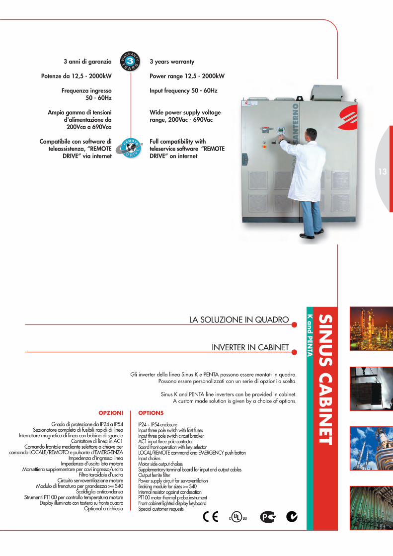
Gli inverter della linea Sinus K e PENTA possono essere montati in quadro.Possono essere personalizzati con un serie di opzioni a scelta.
Sinus K and PENTA line inverters can be provided in cabinet.A custom made solution is given by a choice of options.
3 years warranty
Power range 12,5 - 2000kW
Input frequency 50 - 60Hz
Wide power supply voltagerange, 200Vac - 690Vac
Full compatibility withteleservice software “REMOTEDRIVE” on internet
3 anni di garanzia
Potenze da 12,5 - 2000kW
Frequenza ingresso50 - 60Hz
Ampia gamma di tensionid'alimentazione da200Vca a 690Vca
Compatibile con software diteleassistenza, “REMOTE
DRIVE” via internet
R
EMOTE
D R I VE
R
E TE
D R I VE
13
SINU
S CA
BIN
ETK
and P
ENTA
OPTIONS
IP24 ÷ IP54 enclosureInput three pole switch with fast fusesInput three pole switch circuit breakerAC1 input three pole contactorBoard front operation with key selectorLOCAL/REMOTE command and EMERGENCY push-bottonInput chokesMotor side output chokesSupplementary terminal board for input and output cablesOutput ferrite filterPower supply circuit for servoventilationBraking module for sizes >= S40Internal resistor against condesationPT100 motor thermal probe instrumentFront cabinet lighted display keyboardSpecial customer requests
OPZIONI
Grado di protezione da IP24 a IP54Sezionatore completo di fusibili rapidi di linea
Interruttore magnetico di linea con bobina di sgancioContattore di linea in AC1
Comando frontale mediante selettore a chiave percomando LOCALE/REMOTO e pulsante d’EMERGENZA
Impedenza d’ingresso lineaImpedenza d’uscita lato motore
Morsettiera supplementare per cavi ingresso/uscitaFiltro toroidale d’uscita
Circuito servoventilazione motoreModulo di frenatura per grandezza >= S40
Scaldiglia anticondensaStrumenti PT100 per controllo temperatura motore
Display illuminato con tastiera su fronte quadroOptional a richiesta

PRODUCT SELECTIONThe SINUS’s rating performances can be differentaccording to the admitted rated current and overload(look at LIGHT, STANDARD, HEAVY and STRONGtables). Every single model of inverter can be appliedto 4 different sizes of motor power according to theratings required by the load.
SCELTA DEL PRODOTTOI SINUS sono dimensionati in funzione della correntee del sovraccarico ammesso (vedi tabelle LIGHT,STANDARD, HEAVY e STRONG). Ogni singolomodello d’inverter è applicabile a 4 diverse tagliedi potenza motore in funzione delle prestazionirichieste dal carico.
Tipo di controllo/Control modeK= 2 software a bordo (vedi
caratteristiche tecniche)/2 built-in software (see tech. specs.)
PENTA= 5 software a bordo (vedicaratteristiche tecniche)
/5 built-in software (see tech. specs.)
0005 B 2X4 T A2
Alimentazione/Power Supply2= 200~240Vac;
280~340Vdc4= 380~500Vac;
530~705Vdc5= 500~575Vac;
705~810Vdc6= 575~690Vac;
810~970Vdc
Linea Prodotto/Product LineSINUS
SINUS BOXSINUS CABINET
Alimentazione/Power SupplyT= trifase/3 Phase
S= monofase/Single PhaseC= tensione continua/direct current supply
D= dodecafase/12 impulse bridge
Modulo frenatura/Braking ChopperX= no
B= integrato/integrated
Filtri EMC/FilterI= nessun filtro/no filtersA1= EN55011 gr.1 cl.Afiltro integrato per utenzeindustriali e domestiche/Integratedfilters for industrial and domesticusersA2= EN55011 gr.2 cl.Afiltro integrato per utenzeindustriali/Integrated filters forindustrial usersB= EN55011 gr.1 cl.Bfiltro integrato tipo A1 più toroidein uscita per utenze industriali edomestiche/integrated type A1filter and output ferrite ring forindustrial and domestic users
Tastiera/KeypadX= noK= integrato/integrated
SINUS K
Taglia inverter/Inverter size
Grado di protezione/Enclosure0= IP002= IP203= IP24 ÷ IP314= IP425= IP54C= condizionatore/conditionerS= scambiatore aria-acqua/ air-water exchanger
SIN
US
K a
nd P
ENTA

ELETTRONICASANTERNOInformazioni tecniche più dettagliate sono disponibili su www.elettronicasanterno.it /More technical information available at www.elettronicasanterno.it
Mola-Grinder
Centralina idraulica-Hydraulic power pack
Mulino-Mill
Mulino a sfere-Ball Mill
Mulino a martelli-Hammer Mill
Mulino rotativi-Roller Mill
Miscelatore-Mixer
Pallettizzatore-Palletiser
Piallatrici-Planers
Pompe sommerse-Bore pumps
Pompe centrifughe-centrifugal pumps
Pompe a sfasamento positivo-Positive displacement pumps
Pompe fanghi-Slurry pumps
Spappolatore-Pulper
Tavolo rotativo-Rotary table
Levigatrice-Sander
Sega a nastro-Bandsaw
Sega circolare-Circular saw
Separatore-Separator
Trinciatrice-Shredder
�
�
�
�
�
�
�
�
�
�
�
�
�
�
��
�
��
�
��
�
Settori d’impiego/Applications Sovraccarico/Overload (IST)
STRONGHEAVYLIGHT STANDARD
Vibrovaglio-Vibrating screen
Affettatrice-Slicer
Bottale-Tumbler
Torcitoio/Filatoio-Twister/Spinner
Lavatrici industriali-Industrial washers
Telai-Looms
�
�
�
�
SCELTA DEL SOVRACCARICO/OVERLOAD CHOICE
Presse meccaniche-Mechanical presses
Mandrini-Drills
Controllo assi-Axe control
Laminatoi-Mills
Profilatrici-Forming machines
Cesoie-Shears
Avvolgitori/Svolgitori- WindingUnwing machines
Trafile-Drawplates
�
��
�
��
�
�
��
�
��
�
�
STRONG
Agitatore-Agitator
Atomizzatore-Atomizer
Sminuzzatore-Chipper
Compressore a pistoni a carico-Loaded piston compressor
Compressore a pistoni a vuoto-Unloaded piston compressor
Compressore a vite a carico-Screw Compressor loaded
Compressore a vite a vuoto-Screw Compressor unloaded
Nastro di trasporto-Conveyor belt
Rulliera-Conveyor roller
Coclea -Conveyor screw
Frantumatore a cono-Crusher cone
Frantumatore a mascella-Crusher jaw
Frantumatore rotativo-Crusher rotary
Frantumatore ad impatto verticale-Crusher vertical impact
Scortecciatore-Debarker
Aspiratore-Dust collector
Taglierina-Edger
Ventilatore assiale con smorzatore-Damped axial fan
Ventilatore assiale non smorzato-Undamped axial fan
Ventilatore centrifugo con smorzatore-Centrifugal damped fan
Ventilatore ad alta pressione-High pressure fan
HEAVYLIGHT STANDARD
�
�
�
�
�
�
�
�
�
�
�
�
�
�
�
�
�
�
�
�
�
�
Settori d’impiego/Applications Sovraccarico/Overload (IST)
�
�
Lava bottiglie-Bottle washer
Centrifuga-Centrifuge
Essiccatore-Dryer � �
Ventilatore centrifugo non smorzato-Undamped centrifugal fan
�
� �
�
Sollevamento-Elevators
Traslazione gru e carroponte-Hoists and cranes’ translation
Calandre-Calenders
Presse iniezione, vite-Screw injection moulding machines
Presse iniezione, centralina idraulica-Hydraulic power pack injection
moulding machines
Estrusori-Extruders
�
�
�
� �
�
�
��
Queste tabelle sono da ritenersi indicative/The above tables are intended as a guide only
15

SIN
US
K a
nd P
ENTA
LIGHT overload up to 120%Per carichi con coppia costante-quadratica/For loads with constant-quadratic torque
SizeModello Inverter/
Inverter Model
Potenza motore applicabile/Applicable motor power **Inom.inverter
A
Imaxinverter
A200-240Vac 380-415Vac 440-460Vac 480-500Vac
kW HP A kW HP A kW HP A kW HP A
S05
SINUS0 005 2,2 3 8,5 4,5 6 9,0 5,5 7,5 9,7 6,5 9 10,2 10,5 11,5
SINUS 0007 3 4 11,2 5,5 7,5 11,2 7,5 10 12,5 7,5 10 11,8 12,5 13,5
SINUS 0009 4,5 6 15,7 7,5 10 14,5 9,2 12,5 15,6 9,2 12,5 14,3 16,5 17,5
SINUS 0011 4,5 6 15,7 7,5 10 14,8 9,2 12,5 15,6 11 15 16,5 16,5 21
SINUS 0014 4,5 6 15,7 7,5 10 14,8 9,2 12,5 15,6 11 15 16,5 16,5 25
S10
SINUS 0016 7,5 10 25,7 11 15 21 15 20 25 15 20 23,2 26 30
SINUS 0017 9,2 12,5 30 15 20 29 18,5 25 30 18,5 25 28 30 32
SINUS 0020 9,2 12,5 30 15 20 29 18,5 25 30 18,5 25 28 30 36
SINUS 0025 12,5 17 41 22 30 41 22 30 36 22 30 33 41 48
SINUS 0030 12,5 17 41 22 30 41 22 30 36 25 35 37 41 56
SINUS 0035 12,5 17 41 22 30 41 22 30 36 28 38 41 41 72
S15
SINUS 0038 18,5 25 61 30 40 55 37 40 58 45 60 64 65 75
SINUS 0040 22 30 71 37 50 67 45 60 70 50 70 70 72 75
SINUS 0049 25 35 80 45 60 80 50 65 75 55 75 78 80 96
S20
SINUS 0060 28 38 88 50 70 87 55 75 85 65 90 88 88 112
SINUS 0067 30 40 96 55 75 98 65 90 100 75 100 103 103 118
SINUS 0074 37 50 117 65 90 114 75 100 116 85 115 120 120 144
SINUS 0086 45 60 135 75 100 133 90 125 135 90 125 127 135 155
S30
SINUS 0113 55 75 170 100 135 180 110 150 166 132 180 180 180 200
SINUS 0129 65 90 195 110 150 191 125 170 192 140 190 195 195 215
SINUS 0150 70 95 213 120 165 212 132 180 198 150 200 211 215 270
SINUS 0162 75 100 231 132 180 228 150 200 230 175 238 240 240 290
S40
SINUS 0179 90 125 277 160 220 273 200 270 297 220 300 300 300 340
SINUS 0200 110 150 332 200 270 341 220 300 326 250 340 337 345 365
SINUS 0216 120 165 375 220 300 375 250 340 366 260 350 359 375 430
SINUS 0250 132 180 390 230 315 390 260 350 390 280 380 390 390 480
S501)
SINUS 0312 160 220 475 280 380 480 315 430 459 355 480 471 480 600
SINUS 0366 185 250 550 315 430 528 375 510 540 400 550 544 550 660
SINUS 0399 200 270 593 375 510 621 400 550 591 450 610 612 630 720
S601)SINUS 0457 250 340 732 400 550 680 450 610 665 500 680 673 720 880
SINUS 0524 260 350 780 450 610 765 500 680 731 560 760 751 800 960
S651)
SINUS 0598 300 400 898 500 680 841 560 760 817 630 860 864 900 1100
SINUS 0748 330 450 985 560 760 939 630 860 939 710 970 960 1000 1300
SINUS 0831 400 550 1183 710 970 1200 800 1090 1160 900 1230 1184 1200 1440
*S751)
SINUS 0964 500 680 1463 900 1230 1480 1000 1360 1431 1100 1500 1480 1480 1780
SINUS 1130 560 770 1633 1000 1360 1646 1170 1600 1700 1270 1730 1700 1700 2040
SINUS 1296 630 860 1878 1170 1600 1950 1340 1830 1950 1460 1990 1950 1950 2340
Tensione alimentazioneinverter/Inverter power
supply
200-240Vac;280-360Vdc 380-500Vac; 530-705Vdc
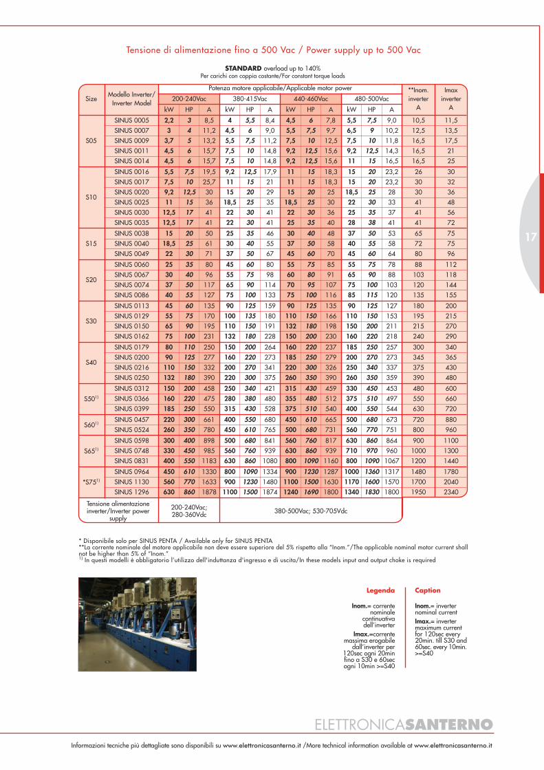
* Disponibile solo per SINUS PENTA / Available only for SINUS PENTA**La corrente nominale del motore applicabile non deve essere superiore del 5% rispetto alla “Inom.”/The applicable nominal motor current shallnot be higher than 5% of “Inom.”1) In questi modelli è obbligatorio l’utilizzo dell'induttanza d'ingresso e di uscita/In these models input and output choke is required
Legenda
Inom.= correntenominale
continuativadell’inverter
Imax.=correntemassima erogabile
dall’inverter per120sec ogni 20minfino a S30 e 60secogni 10min >=S40
Caption
Inom.= inverternominal currentImax.= invertermaximum currentfor 120sec every20min. till S30 and60sec. every 10min.>=S40
Tensione di alimentazione fino a 500 Vac / Power supply up to 500 Vac
ELETTRONICASANTERNOInformazioni tecniche più dettagliate sono disponibili su www.elettronicasanterno.it /More technical information available at www.elettronicasanterno.it
17
STANDARD overload up to 140%Per carichi con coppia costante/For constant torque loads
SizeModello Inverter/
Inverter Model
Potenza motore applicabile/Applicable motor power **Inom.inverter
A
Imaxinverter
A200-240Vac 380-415Vac 440-460Vac 480-500Vac
kW HP A kW HP A kW HP A kW HP A
S05
SINUS 0005 2,2 3 8,5 4 5,5 8,4 4,5 6 7,8 5,5 7,5 9,0 10,5 11,5
SINUS 0007 3 4 11,2 4,5 6 9,0 5,5 7,5 9,7 6,5 9 10,2 12,5 13,5
SINUS 0009 3,7 5 13,2 5,5 7,5 11,2 7,5 10 12,5 7,5 10 11,8 16,5 17,5
SINUS 0011 4,5 6 15,7 7,5 10 14,8 9,2 12,5 15,6 9,2 12,5 14,3 16,5 21
SINUS 0014 4,5 6 15,7 7,5 10 14,8 9,2 12,5 15,6 11 15 16,5 16,5 25
S10
SINUS 0016 5,5 7,5 19,5 9,2 12,5 17,9 11 15 18,3 15 20 23,2 26 30
SINUS 0017 7,5 10 25,7 11 15 21 11 15 18,3 15 20 23,2 30 32
SINUS 0020 9,2 12,5 30 15 20 29 15 20 25 18,5 25 28 30 36
SINUS 0025 11 15 36 18,5 25 35 18,5 25 30 22 30 33 41 48
SINUS 0030 12,5 17 41 22 30 41 22 30 36 25 35 37 41 56
SINUS 0035 12,5 17 41 22 30 41 25 35 40 28 38 41 41 72
S15
SINUS 0038 15 20 50 25 35 46 30 40 48 37 50 53 65 75
SINUS 0040 18,5 25 61 30 40 55 37 50 58 40 55 58 72 75
SINUS 0049 22 30 71 37 50 67 45 60 70 45 60 64 80 96
S20
SINUS 0060 25 35 80 45 60 80 55 75 85 55 75 78 88 112
SINUS 0067 30 40 96 55 75 98 60 80 91 65 90 88 103 118
SINUS 0074 37 50 117 65 90 114 70 95 107 75 100 103 120 144
SINUS 0086 40 55 127 75 100 133 75 100 116 85 115 120 135 155
S30
SINUS 0113 45 60 135 90 125 159 90 125 135 90 125 127 180 200
SINUS 0129 55 75 170 100 135 180 110 150 166 110 150 153 195 215
SINUS 0150 65 90 195 110 150 191 132 180 198 150 200 211 215 270
SINUS 0162 75 100 231 132 180 228 150 200 230 160 220 218 240 290
S40
SINUS 0179 80 110 250 150 200 264 160 220 237 185 250 257 300 340
SINUS 0200 90 125 277 160 220 273 185 250 279 200 270 273 345 365
SINUS 0216 110 150 332 200 270 341 220 300 326 250 340 337 375 430
SINUS 0250 132 180 390 220 300 375 260 350 390 260 350 359 390 480
S501)
SINUS 0312 150 200 458 250 340 421 315 430 459 330 450 453 480 600
SINUS 0366 160 220 475 280 380 480 355 480 512 375 510 497 550 660
SINUS 0399 185 250 550 315 430 528 375 510 540 400 550 544 630 720
S601)SINUS 0457 220 300 661 400 550 680 450 610 665 500 680 673 720 880
SINUS 0524 260 350 780 450 610 765 500 680 731 560 770 751 800 960
S651)
SINUS 0598 300 400 898 500 680 841 560 760 817 630 860 864 900 1100
SINUS 0748 330 450 985 560 760 939 630 860 939 710 970 960 1000 1300
SINUS 0831 400 550 1183 630 860 1080 800 1090 1160 800 1090 1067 1200 1440
*S751)
SINUS 0964 450 610 1330 800 1090 1334 900 1230 1287 1000 1360 1317 1480 1780
SINUS 1130 560 770 1633 900 1230 1480 1100 1500 1630 1170 1600 1570 1700 2040
SINUS 1296 630 860 1878 1100 1500 1874 1240 1690 1800 1340 1830 1800 1950 2340
Tensione alimentazioneinverter/Inverter power
supply
200-240Vac;280-360Vdc 380-500Vac; 530-705Vdc
* Disponibile solo per SINUS PENTA / Available only for SINUS PENTA**La corrente nominale del motore applicabile non deve essere superiore del 5% rispetto alla “Inom.”/The applicable nominal motor current shallnot be higher than 5% of “Inom.”1) In questi modelli è obbligatorio l’utilizzo dell'induttanza d'ingresso e di uscita/In these models input and output choke is required
Legenda
Inom.= correntenominale
continuativadell’inverter
Imax.=correntemassima erogabile
dall’inverter per120sec ogni 20minfino a S30 e 60secogni 10min >=S40
Caption
Inom.= inverternominal currentImax.= invertermaximum currentfor 120sec every20min. till S30 and60sec. every 10min.>=S40
Tensione di alimentazione fino a 500 Vac / Power supply up to 500 Vac

HEAVY overload up to175%Per carichi pesanti con coppia costante/For heavy loads with constant torque
SizeModello Inverter/
Inverter Model
Potenza motore applicabile/Applicable motor power **Inom.inverter
A
Imaxinverter
A200-240Vac 380-415Vac 440-460Vac 480-500Vac
kW HP A kW HP A kW HP A kW HP A
S05
SINUS 0005 1,8 2,5 7,3 3 4 6,4 3,7 5 6,6 4,5 6 7,2 10,5 11,5
SINUS 0007 2,2 3 8,5 4 5,5 8,4 4,5 6 7,8 5,5 7,5 9,0 12,5 13,5
SINUS 0009 3 4 11,2 4,5 6 9,0 5,5 7,5 9,7 7,5 10 11,8 16,5 17,5
SINUS 0011 3,7 5 13,2 5,5 7,5 11,2 7,5 10 12,5 9,2 12,5 14,3 16,5 21
SINUS 0014 4,5 6 15,7 7,5 10 14,8 9,2 12,5 15,6 11 15 16,5 16,5 25
S10
SINUS 0016 5,5 7,5 19,5 9,2 12,5 17,9 11 15 18,3 12,5 17 18,9 26 30
SINUS 0017 5,5 7,5 19,5 9,2 12,5 17,9 11 15 18,3 12,5 17 18,9 30 32
SINUS 0020 7,5 10 25,7 11 15 21 15 20 25 15 20 23,2 30 36
SINUS 0025 9,2 12,5 30 15 20 29 18,5 25 30 18,5 25 28 41 48
SINUS 0030 11 15 36 18,5 25 35 22 30 36 22 30 33 41 56
SINUS 0035 12,5 17 41 22 30 41 25 35 40 28 38 41 41 72
S15
SINUS 0038 15 20 50 25 35 46 30 40 48 30 40 44 65 75
SINUS 0040 15 20 50 25 35 46 30 40 48 37 50 53 72 75
SINUS 0049 18,5 25 61 30 40 55 37 50 58 45 60 64 80 96
S20
SINUS 0060 22 30 71 37 50 67 45 60 70 50 70 70 88 112
SINUS 0067 25 35 80 45 60 80 50 70 75 55 75 78 103 118
SINUS 0074 30 40 96 50 70 87 55 75 85 65 90 88 120 144
SINUS 0086 32 45 103 55 75 98 65 90 100 75 100 103 135 155
S30
SINUS 0113 45 60 135 75 100 133 75 100 116 90 125 127 180 200
SINUS 0129 50 70 150 80 110 144 90 125 135 110 150 153 195 215
SINUS 0150 55 75 170 90 125 159 110 150 166 132 180 180 215 270
SINUS 0162 65 90 195 110 150 191 132 180 198 140 190 191 240 290
S40
SINUS 0179 75 100 231 120 165 212 150 200 230 160 220 218 300 340
SINUS 0200 80 110 250 132 180 228 160 220 237 185 250 257 345 365
SINUS 0216 90 125 277 150 200 264 185 250 279 200 270 273 375 430
SINUS 0250 110 150 332 185 250 321 220 300 326 220 300 300 390 480
S501)
SINUS 0312 132 180 390 220 300 375 260 350 390 300 400 413 480 600
SINUS 0366 150 200 458 250 340 421 300 400 449 330 450 453 550 660
SINUS 0399 160 220 475 280 380 480 330 450 493 355 480 471 630 720
S601)SINUS 0457 200 270 593 315 430 528 375 510 540 450 610 612 720 880
SINUS 0524 220 300 661 355 480 589 450 610 665 500 680 673 800 960
S651)
SINUS 0598 250 340 732 400 550 680 500 680 731 560 760 751 900 1100
SINUS 0748 280 380 840 500 680 841 560 760 817 630 860 864 1000 1300
SINUS 0831 330 450 985 560 760 939 630 860 939 710 970 960 1200 1440
*S751)
SINUS 0964 400 550 1183 710 970 1200 800 1090 1160 900 1230 1184 1480 1780
SINUS 1130 450 620 1330 800 1090 1334 900 1230 1287 1000 1360 1317 1700 2040
SINUS 1296 560 770 1633 900 1230 1480 1100 1500 1630 1170 1600 1560 1950 2340
Tensione alimentazioneinverter/Inverter power
supply
200-240Vac;280-360Vdc 380-500Vac; 530-705Vdc
Tensione di alimentazione fino a 500 Vac / Power supply up to 500 Vac
* Disponibile solo per SINUS PENTA / Available only for SINUS PENTA**La corrente nominale del motore applicabile non deve essere superiore del 5% rispetto alla “Inom.”/The applicable nominal motor current shallnot be higher than 5% of “Inom.”1) In questi modelli è obbligatorio l’utilizzo dell'induttanza d'ingresso e di uscita/In these models input and output choke is required
Legenda
Inom.= correntenominale
continuativadell’inverter
Imax.=correntemassima erogabile
dall’inverter per120sec ogni 20minfino a S30 e 60secogni 10min >=S40
Caption
Inom.= inverternominal currentImax.= invertermaximum currentfor 120sec every20min. till S30 and60sec. every 10min.>=S40
SIN
US
K a
nd P
ENTA

ELETTRONICASANTERNOInformazioni tecniche più dettagliate sono disponibili su www.elettronicasanterno.it /More technical information available at www.elettronicasanterno.it
STRONG overload up to 200%Per carichi gravosi con coppia costante/For strong loads with constant torque
SizeModello Inverter/
Inverter Model
Potenza motore applicabile/Applicable motor power **Inom.inverter
A
Imaxinverter
A200-240Vac 380-415Vac 440-460Vac 480-500Vac
kW HP A kW HP A kW HP A kW HP A
S05
SINUS 0005 1,5 2 6,1 2,2 3 4,9 3 4 5,6 3,7 5 6,1 10,5 11,5
SINUS 0007 1,8 2,5 7,3 3 4 6,4 3,7 5 6,6 4,5 6 7,2 12,5 13,5
SINUS 0009 2,2 3 8,5 4 5,5 8,4 4,5 6 7,8 5,5 7,5 9,0 16,5 17,5
SINUS 0011 3 4 11,2 4,5 6 9,0 5,5 7,5 9,7 7,5 10 11,8 16,5 21
SINUS 0014 3,7 5 13,2 5,5 7,5 11,2 7,5 10 12,5 9,2 12,5 14,3 16,5 25
S10
SINUS 0016 4 5,5 14,6 7,5 10 14,8 9,2 12,5 15,6 11 15 16,5 26 30
SINUS 0017 4,5 6 15,7 7,5 10 14,8 9,2 12,5 15,6 12,5 17 18,9 30 32
SINUS 0020 5,5 7,5 19,5 9,2 12,5 17,9 11 15 18,3 12,5 17 18,9 30 36
SINUS 0025 7,5 10 25,7 11 15 21 15 20 25 15 20 23,2 41 48
SINUS 0030 9,2 12,5 30 15 20 29 18,5 25 30 18,5 25 28 41 56
SINUS 0035 11 15 36 18,5 25 35 22 30 36 22 30 33 41 72
S15
SINUS 0038 12,5 17 41 22 30 41 25 35 40 28 38 41 65 75
SINUS 0040 12,5 17 41 22 30 41 25 35 40 30 40 44 72 75
SINUS 0049 15 20 50 25 35 46 30 40 48 37 50 53 80 96
S20
SINUS 0060 18,5 25 61 30 40 55 37 50 58 45 60 64 88 112
SINUS 0067 20 27 66 32 45 59 40 55 63 50 70 70 103 118
SINUS 0074 22 30 71 37 50 67 45 60 70 55 75 78 120 144
SINUS 0086 25 35 80 45 60 80 55 75 85 65 90 88 135 155
S30
SINUS 0113 30 40 96 55 75 98 65 88 100 75 100 103 180 200
SINUS 0129 37 50 117 65 90 114 75 100 116 85 115 120 195 215
SINUS 0150 45 60 135 75 100 133 90 125 135 90 125 127 215 270
SINUS 0162 55 75 170 90 125 159 110 150 166 110 150 153 240 290
S40
SINUS 0179 60 85 185 100 135 180 120 165 184 132 180 180 300 340
SINUS 0200 65 90 195 110 150 191 132 180 198 150 200 211 345 365
SINUS 0216 75 100 231 120 165 212 150 200 230 160 220 218 375 430
SINUS 0250 90 125 277 132 180 228 185 250 279 200 270 273 390 480
S501)
SINUS 0312 110 150 332 185 250 321 220 300 326 250 340 337 480 600
SINUS 0366 120 165 375 200 270 341 250 340 366 260 350 359 550 660
SINUS 0399 132 180 390 220 300 375 260 350 390 300 400 413 630 720
S601)SINUS 0457 160 220 475 280 380 480 330 450 493 375 510 497 720 880
SINUS 0524 185 250 550 315 430 528 375 510 540 400 550 544 800 960
S651)
SINUS 0598 200 270 593 355 480 589 400 550 591 450 610 612 900 1100
SINUS 0748 250 340 732 400 550 680 500 680 731 560 760 751 1000 1300
SINUS 0831 280 380 840 450 610 765 560 760 817 630 860 864 1200 1440
*S751)
SINUS 0964 355 480 1024 560 770 939 710 970 1043 800 1090 1067 1480 1780
SINUS 1130 400 550 1183 710 970 1200 800 1090 1160 900 1230 1184 1700 2040
SINUS 1296 450 610 1330 800 1090 1334 900 1230 1287 1000 1360 1317 1950 2340
Tensione alimentazioneinverter/Inverter power
supply
200-240Vac;280-360Vdc 380-500Vac; 530-705Vdc
Tensione di alimentazione fino a 500 Vac / Power supply up to 500 Vac
* Disponibile solo per SINUS PENTA / Available only for SINUS PENTA**La corrente nominale del motore applicabile non deve essere superiore del 5% rispetto alla “Inom.”/The applicable nominal motor current shallnot be higher than 5% of “Inom.”1) In questi modelli è obbligatorio l’utilizzo dell'induttanza d'ingresso e di uscita/In these models input and output choke is required
Legenda
Inom.= correntenominale
continuativadell’inverter
Imax.=correntemassima erogabile
dall’inverter per120sec ogni 20minfino a S30 e 60secogni 10min >=S40
Caption
Inom.= inverternominal currentImax.= invertermaximum currentfor 120sec every20min. till S30 and60sec. every 10min.>=S40
19
SIN
US
K a
nd P
ENTA
* Disponibile solo per SINUS PENTA / Available only for SINUS PENTA**La corrente nominale del motore applicabile non deve essere superiore del 5% rispetto alla “Inom.”/The applicable nominal motor current shallnot be higher than 5% of “Inom.”1) In questi modelli è obbligatorio l’utilizzo dell'induttanza d'ingresso e di uscita/In these models input and output choke is required
Legenda
Inom.= correntenominale
continuativadell’inverter
Imax.=correntemassima erogabile
dall’inverter per120sec ogni 20minfino a S30 e 60secogni 10min >=S40
Caption
Inom.= inverternominal currentImax.= invertermaximum currentfor 120sec every20min. till S30 and60sec. every 10min.>=S40
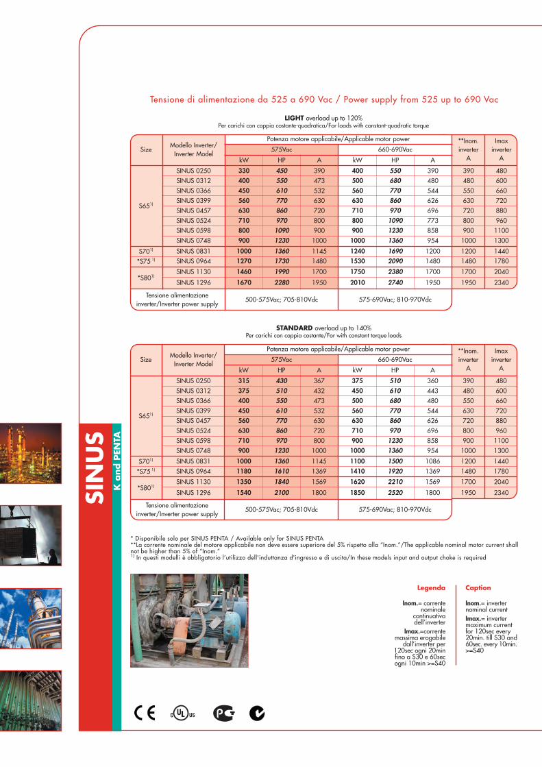
LIGHT overload up to 120%Per carichi con coppia costante-quadratica/For loads with constant-quadratic torque
Tensione di alimentazione da 525 a 690 Vac / Power supply from 525 up to 690 Vac
SizeModello Inverter/
Inverter Model
Potenza motore applicabile/Applicable motor power **Inom.inverter
A
Imaxinverter
A575Vac 660-690Vac
kW HP A kW HP A
S651)
SINUS 0250 330 450 390 400 550 390 390 480SINUS 0312 400 550 473 500 680 480 480 600SINUS 0366 450 610 532 560 770 544 550 660SINUS 0399 560 770 630 630 860 626 630 720SINUS 0457 630 860 720 710 970 696 720 880SINUS 0524 710 970 800 800 1090 773 800 960SINUS 0598 800 1090 900 900 1230 858 900 1100SINUS 0748 900 1230 1000 1000 1360 954 1000 1300
S701) SINUS 0831 1000 1360 1145 1240 1690 1200 1200 1440
*S75 1) SINUS 0964 1270 1730 1480 1530 2090 1480 1480 1780
*S801)SINUS 1130 1460 1990 1700 1750 2380 1700 1700 2040
SINUS 1296 1670 2280 1950 2010 2740 1950 1950 2340
Tensione alimentazioneinverter/Inverter power supply
500-575Vac; 705-810Vdc 575-690Vac; 810-970Vdc
SizeModello Inverter/
Inverter Model
Potenza motore applicabile/Applicable motor power **Inom.inverter
A
Imaxinverter
A575Vac 660-690Vac
kW HP A kW HP A
S651)
SINUS 0250 315 430 367 375 510 360 390 480SINUS 0312 375 510 432 450 610 443 480 600SINUS 0366 400 550 473 500 680 480 550 660SINUS 0399 450 610 532 560 770 544 630 720SINUS 0457 560 770 630 630 860 626 720 880SINUS 0524 630 860 720 710 970 696 800 960SINUS 0598 710 970 800 900 1230 858 900 1100SINUS 0748 900 1230 1000 1000 1360 954 1000 1300
S701) SINUS 0831 1000 1360 1145 1100 1500 1086 1200 1440
*S75 1) SINUS 0964 1180 1610 1369 1410 1920 1369 1480 1780
*S801)SINUS 1130 1350 1840 1569 1620 2210 1569 1700 2040
SINUS 1296 1540 2100 1800 1850 2520 1800 1950 2340
Tensione alimentazioneinverter/Inverter power supply
500-575Vac; 705-810Vdc 575-690Vac; 810-970Vdc
STANDARD overload up to 140%Per carichi con coppia costante/For with constant torque loads

SizeModello Inverter/
Inverter Model
Potenza motore applicabile/Applicable motor power **Inom.inverter
A
Imaxinverter
A575Vac 660-690Vac
kW HP A kW HP A
S651)
SINUS 0250 220 300 261 280 380 278 390 480SINUS 0312 280 380 334 355 480 341 480 600SINUS 0366 315 430 367 375 510 360 550 660SINUS 0399 355 480 410 400 550 390 630 720SINUS 0457 400 550 473 500 680 480 720 880SINUS 0524 450 610 532 560 770 544 800 960SINUS 0598 560 770 630 630 860 626 900 1100SINUS 0748 630 860 720 800 1090 773 1000 1300
S701) SINUS 0831 710 970 800 900 1230 858 1200 1440
*S75 1) SINUS 0964 900 1230 1000 1000 1360 954 1480 1780
*S801)SINUS 1130 1000 1360 1145 1100 1500 1086 1700 2040
SINUS 1296 1150 1570 1337 1380 1880 1337 1950 2340
Tensione alimentazioneinverter/Inverter power supply
500-575Vac; 705-810Vdc 575-690Vac; 810-970Vdc
ELETTRONICASANTERNO
21
Informazioni tecniche più dettagliate sono disponibili su www.elettronicasanterno.it /More technical information available at www.elettronicasanterno.it
* Disponibile solo per SINUS PENTA / Available only for SINUS PENTA**La corrente nominale del motore applicabile non deve essere superiore del 5% rispetto alla “Inom.”/The applicable nominal motor current shallnot be higher than 5% of “Inom.”1) In questi modelli è obbligatorio l’utilizzo dell'induttanza d'ingresso e di uscita/In these models input and output choke is required
Legenda
Inom.= correntenominale
continuativadell’inverter
Imax.=correntemassima erogabile
dall’inverter per120sec ogni 20minfino a S30 e 60secogni 10min >=S40
Caption
Inom.= inverternominal currentImax.= invertermaximum currentfor 120sec every20min. till S30 and60sec. every 10min.>=S40
HEAVY overload up to 175%Per carichi pesanti con coppia costante/For heavy loads with constant torque
Tensione di alimentazione da 525 a 690 Vac / Power supply from 525 up to 690 Vac
STONG overload up to 200%Per carichi gravosi con coppia costante/For strong loads with constant torque
SizeModello Inverter/
Inverter Model
Potenza motore applicabile/Applicable motor power **Inom.inverter
A
Imaxinverter
A575Vac 660-690Vac
kW HP A kW HP A
S651)
SINUS 0250 280 380 334 330 450 328 390 480SINUS 0312 355 480 410 400 550 390 480 600SINUS 0366 375 510 432 450 610 443 550 660SINUS 0399 400 550 473 500 680 480 630 720SINUS 0457 500 680 585 560 770 544 720 880SINUS 0524 560 770 630 630 860 626 800 960SINUS 0598 630 860 720 710 970 696 900 1100SINUS 0748 710 970 800 900 1230 858 1000 1300
S701) SINUS 0831 800 1090 900 1000 1360 954 1200 1440
*S75 1) SINUS 0964 1000 1360 1145 1220 1660 1187 1480 1780
*S801)SINUS 1130 1170 1600 1360 1400 1910 1360 1700 2040
SINUS 1296 1340 1830 1560 1610 2190 1560 1950 2340
Tensione alimentazioneinverter/Inverter power supply
500-575Vac; 705-810Vdc 575-690Vac; 810-970Vdc

Size
(mm) (kg)
Pesi/Weight
Dimensioni/DimensionsLxHxP/WxHxD
S10
S15
S30
S40
S50
215x391x216
225x466x331
302x748x421
630x880x381
666x1000x421
11,5
22,5
51
112
148
170x340x175S05
36S20 279x610x332
7
model IP20 and IP00
S60 890x1310x530 260
S65 980x1400x560 440
S70 1230x1400x560 550
S75 1980x1400x560 880S80 2230x1400x560 990
S50
S60
S65
S05S10 S15 S20 S30
Dimensione e pesi modello IP20 / Dimensions and weight IP20 models
SIN
US
K a
nd P
ENTA
S40

SINUS IP54
The Sinus series offers, moreover, a range with IP54protection degree suitable for environmental conditionswith strong presence of dusts and water(up to Sinus 0162).
Thanks to its robust metallic structure suitable for externalinstallation, it is not necessary to insert this model intoany electric cabinet.
Main supply, Motor supply and Control board connectionare reachable from below by means of the insertion ofsuitable cable-bushings.
It is also possible to add a complete operation board onthe front door for the emergency command and theselection of the following 3 functions by key lock selector:
SINUS IP54
La serie Sinus offre inoltre una gamma in grado diprotezione IP54 per installazione in condizioni ambientalicon forte presenza di polveri ed acqua(fino a Sinus 0162).
Struttura metallica robusta adatta ad installazioni esterneche non necessita di inserimento in quadri elettrici.
Arrivo linea, Partenza motore e Controllo sono accessibilidal basso attraverso l’inserimento di pressacavi idonei.
È inoltre possibile inserire su richiesta una manovracompleta sul pannello frontale per il comando diemergenza e la selezione mediante selettore a chiavedi 3 funzioni:
LOCALE (LOC): Permette di manovrare e regolarela velocità motore attraverso latastiera dell’inverter (Start, Stop eRegolazione velocità)
0 (ZERO) In questa posizione l’inverter èdisabilitato al funzionamento
REMOTO (REM) Permette di gestire l’inverter infunzione di come esso èp rog ramma to , a t t r a ve r somorsettiera, porta seriale o bus dicampo
LOCAL (LOC): It is possible to operate and adjustMotor speed by the inverter’skeypad(Start, Stop and Speed adjustment)
0 (ZERO) In this position, the inverter isunable to work
REMOTE (REM) It allows to manage the inverteraccording to its programming byterminal board, serial port orfieldbus
Dimensione e pesi modello IP54 / Dimensions and weight IP54 models
ELETTRONICASANTERNOInformazioni tecniche più dettagliate sono disponibili su www.elettronicasanterno.it /More technical information available at www.elettronicasanterno.it
23
model IP54
Size
(mm) (kg)
Pesi/Weight
Dimensioni/DimensionsLxHxP/WxHxD
S10
S15
S30
250x622x268
288x715x366
359x1008x460
23,3
40
76
214x577x227S05
57S20 339x842x366
15,7
S30 S20 S15 S10 S05

SIN
US
K a
nd P
ENTA
CABINET model
Dimensioni/DimensionsLxAxP/WxHxD
1000x2000x600
1200x2000x600
1600x2350x800
2200x2350x800
S40C
S50C
S60C
S70C
S30C
S20C 600x2000x500
600x2000x600
(mm) (kg)
Pesi/Weight
162
279
586
1007
350
143
*Dimensioni e pesi possono variare in funzione degli optional richiesti.*Dimensions and weights may change according to the optionals required.
Size
2000x2350x800S65C 854
S15C 600x2000x500 130
3000x2350x800S75C 1468
3400x2350x800S80C 1700
* model BOX IP54
Size
(mm)
Dimensioni/DimensionsLxAxP/WxHxD
S10B
S15B
S20B
500x700x300
600x1000x400
600x1200x400
400x600x250S05B
(kg)
Pesi/Weight
49,5
78,2
112,3
27,9
*Dimensioni e pesi possono variare in funzione degli optional richiesti.*Dimensions and weights may change according to the required optionals.
Dimensione e pesi modelli BOX e CABINET / Dimension and weight BOX and CABINET
BOX S10B
CABINET S65CCABINET S15C
25
SINU
S Accesso
ri/Accesso
ries
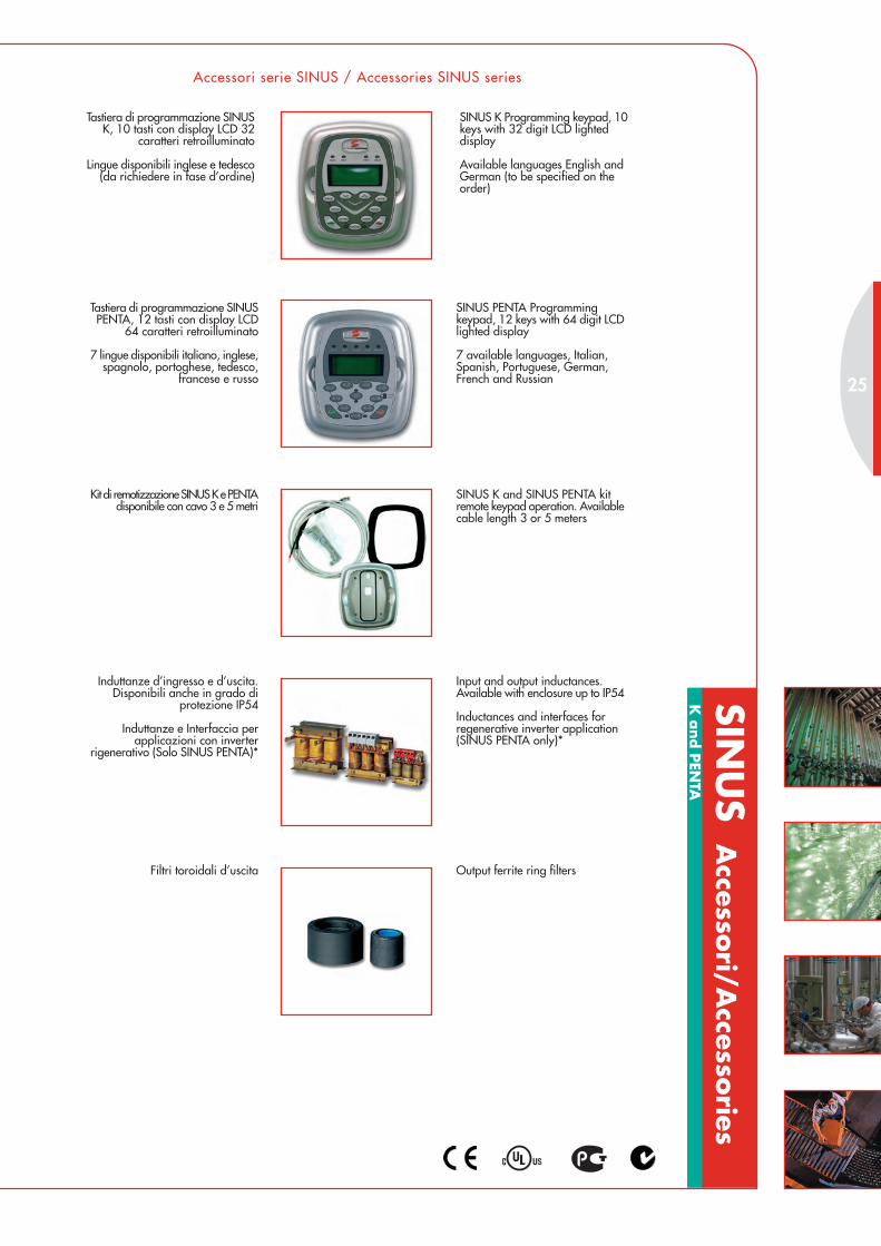
Accessori serie SINUS / Accessories SINUS series
Tastiera di programmazione SINUSK, 10 tasti con display LCD 32
caratteri retroilluminato
Lingue disponibili inglese e tedesco(da richiedere in fase d’ordine)
SINUS K Programming keypad, 10keys with 32 digit LCD lighteddisplay
Available languages English andGerman (to be specified on theorder)
Tastiera di programmazione SINUSPENTA, 12 tasti con display LCD
64 caratteri retroilluminato
7 lingue disponibili italiano, inglese,spagnolo, portoghese, tedesco,
francese e russo
SINUS PENTA Programmingkeypad, 12 keys with 64 digit LCDlighted display
7 available languages, Italian,Spanish, Portuguese, German,French and Russian
Kit di remotizzazione SINUS K e PENTAdisponibile con cavo 3 e 5 metri
SINUS K and SINUS PENTA kitremote keypad operation. Availablecable length 3 or 5 meters
Induttanze d’ingresso e d’uscita.Disponibili anche in grado di
protezione IP54
Induttanze e Interfaccia perapplicazioni con inverter
rigenerativo (Solo SINUS PENTA)*
Input and output inductances.Available with enclosure up to IP54
Inductances and interfaces forregenerative inverter application(SINUS PENTA only)*
Filtri toroidali d’uscita Output ferrite ring filters
K a
nd P
ENTA

Laminated stainless steel in cabinet IP23
SIN
US
Acc
esso
ri/A
cces
sori
es
Accessori serie SINUS / Accessories SINUS series
RESISTENZE E MODULO DI FRENATURA
Modulo di frenatura per taglie ≥ S40
BRAKING UNIT AND RESISTORS
Braking module for sizes ≥ S40
In estruso d’alluminio IP55 Extruded aluminium IP55
A filo contenitore IP20 Wire resistors IP20 enclosure
Di lamina d’acciaio in BOX IP23
Kit ANY BUS COMMUNICATORadatto per la connessione fino a 4drives, convertitore RS485 Modbusin Profibus DP, Devicenet, Canbus
Kit ANY BUS COMMUNICATORsuitable for connection up to 4 drives,RS485 converter ModBus/ProfibusDP, DeviceNet, CanBus
Kit per montaggio potenzaall’esterno dei quadri elettrici
(Di serie dalla grandezza ≥ S15)
Kit for heatsink segregation(Standard up to size ≥ S15)
K a
nd P
ENTA

27
Accessori serie SINUS / Accessories SINUS series
ELETTRONICASANTERNOInformazioni tecniche più dettagliate sono disponibili su www.elettronicasanterno.it /More technical information available at www.elettronicasanterno.it
ES836 Encoder card
ES822, RS232 and/or RS485(This card is suggested in case ofseveral inverters connected inmultidrop ModBus)
ES860 SinCos card(SINUS PENTA only)*
ES861, Revolver/Encoder card withreapeted encoder + 3 digitalinput/output (SINUS PENTA only)*
ES847 expansion card, 8 digitalinputs, 6 digital outputs, 4 analoginput/PT100(SINUS PENTA only)*
ES870 expansion card 12 digitalinputs and 6 relays outputs(SINUS PENTA only)*
Profibus DP card(SINUS PENTA only)*
DeviceNet card(SINUS PENTA only)*
Interbus card(SINUS PENTA only)*
Can Open DP card(SINUS PENTA only)*
ControlNet DP card(SINUS PENTA only)*
Ethernet card(SINUS PENTA only)*
Ethernet +IT card(SINUS PENTA only)*
Scheda encoder ES836
Scheda seriale isolata RS 232 e/oRS485, ES822. (Questa scheda è
consigliata in caso di utilizzo di piùinverter in ModBus network)
Scheda SinCos, ES860(Solo SINUS PENTA)*
Scheda Revolver/Encoder, conEncoder ripetuto + 3 ingressi/uscitedigitali, ES861 (Solo SINUS PENTA)*
Scheda espansione con 8 ingressie 6 uscite digitali e 4 ingressi
analogici/PT100, ES847(Solo SINUS PENTA)*
Scheda espansione con 12 ingressidigitali e 6 uscite a relè, ES870
(Solo SINUS PENTA)*
Scheda Profibus DP(Solo SINUS PENTA)*
Scheda Devicenet(Solo SINUS PENTA)*
Scheda Interbus(Solo SINUS PENTA)*
Scheda Canopen DP(Solo SINUS PENTA)*
Scheda ControlNet DP(Solo SINUS PENTA)*
Scheda Ethernet(Solo SINUS PENTA)*
Scheda Ethernet + IT(Solo SINUS PENTA)*
REMOTE DRIVE software for localprogramming and remote controlvia Internet.A complete kit for PC connection,RS232 or USB, is available.
Multipumps softaware suitable formangement of plants up to 5 pumps(SINUS PENTA only)
Servodiameter software andenanched PID for winder andrewinder controls(SINUS PENTA only)*
Regenerative software for supplyand regenerate at cosϕ=1in aperfectly sinusoidal way form(SINUS PENTA only)
High speed spindle motors softwarefor application up to 2000Hz(SINUS PENTA only)*
Axis control software(SINUS PENTA only)*
Multipositioner software(SINUS PENTA only)*
Software REMOTE DRIVE per laprogrammazione locale e il telecontrollo
a distanza attraverso Internet.È disponibile un kit completo per
connettere PC attraverso portaseriale RS232 o USB.
Software multipompa per la gestioned’impianti fino 5 pompe
(Solo SINUS PENTA).
Software servodiametro e PIDavanzato per il controllo di
avvolgitori e svolgitori(Solo SINUS PENTA)*.
Software rigenerativo perl’assorbimento e la rigenerazione
cosϕ=1 in modo perfettamentesinusoidale dalla rete elettrica
(Solo SINUS PENTA).
Software per motori mandrino finoa 2000Hz (Solo SINUS PENTA)*.
Software asse ellettrico(Solo SINUS PENTA)*.
Software multiposizionatore(Solo SINUS PENTA)*.
* -Disponibili dal 2° semestre 2005- * -Available starting from the 2nd semester 2005-

SIN
US
K S
oft
ware
Lif
t SOFTWARE LIFT A MODULAZIONE VETTORIALE PER ASCENSORI
VECTOR MODULATION LIFT SOFTWARE FOR LIFT APPLICATIONS
3 years warranty
Wide power supply voltagerange, 200Vac - 500Vac
Input frequency 50 - 60Hz
Power range 1,8 - 355kW
Full digital
Full compatibility withteleservice software “REMOTEDRIVE” on internet
3 anni di garanzia
Ampia gamma di tensionid'alimentazione da200Vca a 500Vca
Frequenza ingresso 50 - 60Hz
Potenze da 1,8 - 355kW
Full digital
Compatibile con software diteleassistenza, “REMOTE
DRIVE” via internet
R
EMOTE
D R I VE
R
E TE
D R I VE
3WAR
RANTY
Y
E A R
S

TECHNICAL FEATURES
High comfort and precise positioning without feedback for application withspeed up to 1,2m/sec.Possibility to use speed feedback for lift with speed up to 2,5m/sec.Totally noiseless operation given by carrier frequency up to 16kHzOverload 150-175% for 120sec.Included braking module up to S302 line LCD display, 32 digit, remotable (Optional)3 available speed plus one for maintenanceIntegrated multimeterTrip LogIntegrated thermal protection for motorAutomatic restart in case of inverter stop for alarmS curve with large choice of acceleration values and jerkRegulation of output frequency from 0 to 800 Hz8 programmable inputs with regulation of internal timers2 programmable relays outputs1 open collector outputAuxiliary 24Vdc, 10Vdc2 programmable analog ouputs 0-10Vdc, 0(4)-20mARS485 serial communication with MODBUS RTU protocolEN 81 compliant to lift directiveEMC conform UNI EN 12015 with integrated filters A1 for current below 25Aand A2 filters for current above 25A
OPTIONS
Emergency module BU850“Remote Drive” softwareBraking module for sizes ≥ S40Braking resistorsOutput filtersInput and output chokesRS232/485 converterKit remote keyboard operation (5 metres)Kit potentiometerKit for heatsink segregationEncoder cardConverter for MODBUS/Profibus DP-CanBus-Device Net etc.
CARATTERISTICHE TECNICHE
Elevato comfort e posizionamento senza retroazione per impiego con velocitàa 1,2m/sec.
Possibilità di utilizzare la retroazione di velocità per velocità fino a 2,5m/sec.Frequenza di carrier fino a 16kHz per un funzionamento silenzioso
Sovraccarico ammesso 150-175% per 120sec.Modulo di frenatura compreso fino a S30
Display LCD su due righe, 32 caratteri, remotabile (Opzionale)3 velocità disponibili più una di manutenzione
Tester multifunzionale integratoStorico allarmi
Protezione termica motore intergrataRiavvia automatico in caso di anomalia
Curve a S con ampia possibilità di scelta dei valori di accelerazione e jerkRegolazione della frequenza di uscita da 0 a 800 Hz
8 ingressi digitali programmabili con regolazione di timer interni2 uscite configurabili a relè con contatti in scambio
1 uscita open collectorTensioni ausiliarie 24Vdc, 10Vdc
2 uscite analogiche configurabili 0-10Vdc, 0(4)-20mAComunicazione seriale RS485 con protocollo MODBUS RTU
Conforme alla direttiva ascensori EN81EMC conforme UNI EN 12015 con l’utilizzo di filtri integrati tipo A1 per
correnti inferiori a 25A e tipo A2 per correnti superiori
OPZIONI
Modulo emergenza BU850Software “Remote Drive”
Modulo di frenatura per taglie ≥ S40Resistenze di frenaturaFiltri toroidali d’uscita
Induttanze ingresso e uscitaConvertitore RS232/485
Kit remotizzazione tastiera (5 metri)Kit potenziometro
Kit montaggio passanteScheda encoder
Convertitore MODBUS/Profibus DP-CanBus-Device Net ecc.
ELETTRONICASANTERNO
29
Legenda
Inom.= correntenominale continuativa
dell’inverterImax.=corrente
massima erogabiledall’inverter per 120secogni 20min fino a S30
e 60sec ogni10min >=S40
Caption
Inom.= inverternominal currentImax.= invertermaximum current for120sec every 20min tillS30 and 60sec every10min >=S40
Informazioni tecniche più dettagliate sono disponibili su www.elettronicasanterno.it /More technical information available at www.elettronicasanterno.it
**La corrente nominale del motore applicabile non deve essere superiore del 5% rispetto alla “Inom.”/Theapplicable nominal motor current shall not be higher than 5% of “Inom.”1) In questi modelli è obbligatorio l'utilizzo dell'induttanza d'ingresso e di uscita/ In these models input and outputchoke is required
model LIFT HEAVY overload up to175%
SizeModello Inverter/
Inverter Model
Potenza motore applicabile/Applicable motor power **Inom.inverter
A
Imaxinverter
A200-240Vac 380-415Vac 440-460Vac 480-500Vac
kW HP kW HP kW HP kW HP
S05
SINUS 0005 1,8 2,5 3 4 3,7 5 4,5 6 10,5 11,5 SINUS 0007 2,2 3 4 5,5 4,5 6 5,5 7,5 12,5 13,5 SINUS 0009 3 4 4,5 6 5,5 7,5 7,5 10 16,5 17,5 SINUS 0011 3,7 5 5,5 7,5 7,5 10 9,2 12,5 16,5 21 SINUS 0014 4,5 6 7,5 10 9,2 12,5 11 15 16,5 25
S10
SINUS 0016 5,5 7,5 9,2 12,5 11 15 12,5 17 26 30 SINUS 0017 5,5 7,5 9,2 12,5 11 15 12,5 17 30 32 SINUS 0020 7,5 10 11 15 15 20 15 20 30 36 SINUS 0025 9,2 12,5 15 20 18,5 25 18,5 25 41 48 SINUS 0030 11 15 18,5 25 22 30 22 30 41 56 SINUS 0035 12,5 17 22 30 25 35 28 38 41 72
S15SINUS 0038 15 20 25 35 30 40 30 40 65 75 SINUS 0040 15 20 25 35 30 40 37 50 72 75 SINUS 0049 18,5 25 30 40 37 50 45 60 80 96
S20
SINUS 0060 22 30 37 50 45 60 50 70 88 112 SINUS 0067 25 35 45 60 50 70 55 75 103 118 SINUS 0074 30 40 50 70 55 75 65 90 120 144 SINUS 0086 32 45 55 75 65 90 75 100 135 155
S30
SINUS 0113 45 60 75 100 75 100 90 125 180 200 SINUS 0129 50 70 80 110 90 125 110 150 195 215 SINUS 0150 55 75 90 125 110 150 132 180 215 270 SINUS 0162 65 90 110 150 132 180 140 190 240 290
S40
SINUS 0179 75 100 120 165 150 200 160 220 300 340 SINUS 0200 80 110 132 180 160 220 185 250 345 365 SINUS 0216 90 125 150 200 185 250 200 270 375 430 SINUS 0250 110 150 185 250 220 300 220 300 390 480
S501)
SINUS 0312 132 180 220 300 260 350 300 400 480 600 SINUS 0366 150 200 250 340 300 400 330 450 550 660 SINUS 0399 160 220 280 380 330 450 355 480 630 720
Tensione alimentazioneinverter/Inverter power supply
200-240Vac;280-360Vdc 380-500Vac; 530-705Vdc
model IP20 and IP00
Size
(mm) (kg)
Pesi/Weight
Dimensioni/DimensionsLxHxP/WxHxD
S10S15
S30S40
S50
215x391x216225x466x331
302x748x421630x880x381
666x1000x421
11,522,5
51112
148
170x340x175S05
36S20 279x610x332
7

ESTA
RT
SFTS AVVIATORI STATICI SOFT-START/STOP PER MOTORI ASINCRONI TRIFASE
SOFT START/STOP STATIC STARTERS FOR THREE-PHASE ASYNCHRONOUSMOTORS
1 year warranty
Input voltage 380 - 415 Vac
Input frequency 50 - 60Hz
Power range 1,1kW - 11kW
1 anno di garanzia
Tensione d'alimentazione380 - 415Vca
Frequenza 50 - 60Hz
Potenze da 1,1kW a 11kW

TECHNICAL FEATURES
Start up time regulationStopping time regulationStart up torque regulationInput controls isolated from main supplyIntegrated By-Pass relayIntegrated overvoltage protectionOperation status ledEasy useCompact dimensionEMC conforming to EN 50082-2
OPTIONS
Extra-fast fuses
CARATTERISTICHE TECNICHE
Regolazione tempo di avviamentoRegolazione tempo di arresto
Regolazione della coppia di avviamentoComandi d’ingresso isolati dalla rete
Relè di By-Pass integratoProtezione di sovratensione integrata
Led di indicazioni di statoEstrema semplicità d’utilizzo
Massima compattezzaCompatibilità elettromagnetica secondo EN 50082-2
OPZIONI
Fusibili Extrarapidi
ELETTRONICASANTERNO
31
Informazioni tecniche più dettagliate sono disponibili su www.elettronicasanterno.it /More technical information available at www.elettronicasanterno.it
SFTS. 3/1 18 1,1
SFTS. 12/1 12 72
SFTS. 25/1 25 150 0,5 - 10 0,5 - 20 5 - 50% 11 90x102x92
30,5 - 5 0,5 - 5 0 - 70%
5,545x102x92
Dimensioni/Dimensions
(mm)Tipo/Type
SFTSCorrente
nominale/NominalCurrent
(A)
Correntemassima/
Max Current(A)
Rampad’avviamento
/Start upramp(sec.)
Rampad’arresto/
Stop up ramp(sec.)
Coppiad’avviamento/Starting torque
Motoreapplicabile/Motor power
(kW)
Pesi/Weight(Kg.)
0,310
0,315
0,625

ASA
C0/A
SAC1 s
oft
sta
rter
s AVVIATORI STATICI SOFT-START/STOP PER MOTORI ASINCRONI TRIFASE
SOFT START/STOP STATIC STARTERS FOR THREE-PHASE ASYNCHRONOUSMOTORS
2 years warranty
Range 7,5kW - 110kW
Power supply voltage range200 - 575Vac
Internal By-pass Contactor
Input frequency 50 - 60Hz
Full compatibility withteleservice software“REMOTE DRIVE” on internet
R
EMOTE
D R I VE
R
E TE
D R I VE
ASAC0 è la risposta giusta per chi deve salvare spazio e contenere i costi.Oltre alle caratteristiche di ASAC0, l'ASAC1 garantisce un’affidabile protezione motore e controllo di corrente.
ASAC0 is the right solution to save space and keep costs under control.Besides the features of ASAC0, the ASAC1 grants a reliable motor protection and current control.
WAR
RANTY
Y
E A R
S
22 anni di garanzia
Gamma 7,5kW a 110kW
Tensioni d'alimentazione200 - 575Vac
Contattore di By-pass integrato
Frequenza 50 - 60Hz
Compatibile con software diteleassistenza,
“REMOTE DRIVE” via internet

33
COMMON TECHNICAL FEATURES (ASAC0/ASAC1)
Compact dimensionsInternal By-pass contactor400% max allowed overload of the nominal currentIP20 Enclosure (<=ASAC 55kW)3 Adjustments: Initial start voltage, Start ramp time,Soft stop ramp time6 Indications: No control power, Starter Ready, Starter tripped, Motor notrunning, Motor running at full speed, Motor starting/stopping3 Alarms: Power circuit, Supply frequency,Communication2 digital inputs: Start, Stop1 Output relay: Main contactor relayLocal resetControl power supply: 110-240Vac and 380-440VacPower supply: 200-440Vac ±10% / 200-575Vac ±10%Input frequency: 50-60Hz ±10%
ASAC1 ADDITIONAL FEATURES
8 adjustments: Motor FLC, Current Ramp, Current Limit, Motor Trip Class, SoftStop Time, Excess Start Time, Phase Sequence Protection,Auxiliary Relay Function5 additional Alarms: Excess start time,Motor overload, Motor thermistor, Phase imbalance, Phase sequence1 additional Digital input: Motor thermistor probe1 additional Output relay: Programmable relay
OPTIONS (ASAC0/ASAC1)
24Vac/Vdc Control Power SupplyExtra-fast fusesRS485 Serial communication port with MODBUS RTU DeviceNet, Profibus,ASI protocolRemote control panel (RS485 doubler, one 4-20mA output)RS232/485 converter
ELETTRONICASANTERNOInformazioni tecniche più dettagliate sono disponibili su www.elettronicasanterno.it /More technical information available at www.elettronicasanterno.it
CARATTERISTICHE TECNICHE COMUNI (ASAC0/ASAC1)
Dimensioni compatteBy-pass integrato
Max sovraccarico ammesso 400% della corrente nominaleGrado di protezione IP20 (<=ASAC 55kW)
3 Regolazioni: Tensione iniziale di partenza, Rampa di partenza e Rampadi fermata
6 Segnalazioni: Mancanza alimentazione controllo, Soft starter Pronto,Anomalia Soft starter, Motore fermo, Motore in Marcia, Motore in partenza/fermata
3 Allarmi: Sezione di potenza, Frequenza d’alimentazione,Comunicazione Seriale
2 Ingressi digitali: Start, Stop1 Uscita relè: Comando contattore di linea
Pulsante di resetAlimentazione controllo: 110-240Vac e 380-440Vac
Alimentazione Potenza: 200-440Vac ±10% / 200-575Vac ±10%Frequenza d’ingresso: 50-60Hz ±10%
CARATTERISTICHE ADDIZIONALI ASAC1
8 Regolazioni: Corrente nominale motore, Rampa di corrente, Limite dicorrente, Termica motore, Rampa di fermata, Tempo di partenza eccessivo,
Protezione Senso ciclico, Funzione relè ausiliarioUlteriori 5 allarmi: Tempo di partenza eccessivo, Sovraccarico motore,
Sovratemperatura motore, Sbilanciamento di fase, Senso ciclicoUlteriore Ingresso digitale: Sonda termica motore
Ulteriore uscita a relè: Relè programmabile
OPZIONI (ASAC0/ASAC1)
Tensione alimentazione controllo a 24Vac/VdcFusibili extra-rapidi
Porta seriale RS485 con protocollo MODBUS RTU,DeviceNet, Profibus, ASI
Pannello di controllo remoto (duplicatore RS485, 1 uscita 4-20mA)Convertitore RS232/485
ModelliModels
Dimensioni LxAxPDimensions WxHxD
(mm.)
ASAC 015
ASAC 018
ASAC 022
ASAC 030
98x203x163
ASAC 007
145x215x191
ASAC 055
ASAC 075
ASAC 090
ASAC 110
202x240x212
ASAC 045
ASAC 037
PesiWeight
(Kg)
2,1
4,3
6,8
Modello Soft Starter/Soft Starter Model 200-240Vac
kW380-415Vac
kW440Vac
kW460-500Vac
kW
FLC*A
ASAC0/ASAC1 007ASAC0/ASAC1 015ASAC0/ASAC1 018ASAC0/ASAC1 022ASAC0/ASAC1 030ASAC0/ASAC1 037ASAC0/ASAC1 045ASAC0/ASAC1 055ASAC0/ASAC1 075ASAC0/ASAC1 090ASAC0/ASAC1 110
Potenza motore applicabile / Applicable motor power
4,59,211
22
30
55
1115
22
4555
9,215
18,5
37
55
110
2230
45
7590
9,218,522
45
55
110
3037
55
7590
1118,522
45
55
132
3037
55
90110
112230
55
75
160
3745
55
110132
183442
75
100
200
4860
85
140170
575VackW
Tensione alimentazione Soft-Starter/Soft-Starter power supply 200-440Vac 200-575Vac
*FLC=Corrente nominale a pieno carico/Full load current
Versione/Version:0 = Basic1 = Advanced
Modelli/Models
Alimentazione di Rete/Main Supply4 = 3Ø, 200-440Vac, 45-66Hz5 = 3Ø, 200-575Vac, 45-66Hz
1ASAC 0 0 7 4Alimentazione di Controllo/Control Supply1 = 110-240Vac & 380-440Vac2 = 24Vac/Vdc
/ / / 1
ASA
soft
sta
rter
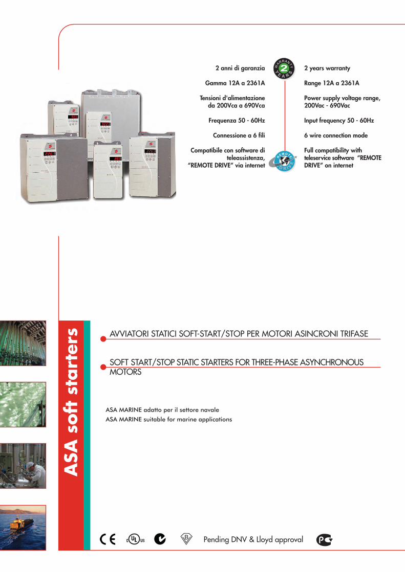
s AVVIATORI STATICI SOFT-START/STOP PER MOTORI ASINCRONI TRIFASE
SOFT START/STOP STATIC STARTERS FOR THREE-PHASE ASYNCHRONOUSMOTORS
2 years warranty
Range 12A a 2361A
Power supply voltage range,200Vac - 690Vac
Input frequency 50 - 60Hz
6 wire connection mode
Full compatibility withteleservice software “REMOTEDRIVE” on internet
2 anni di garanzia
Gamma 12A a 2361A
Tensioni d'alimentazioneda 200Vca a 690Vca
Frequenza 50 - 60Hz
Connessione a 6 fili
Compatibile con software diteleassistenza,
“REMOTE DRIVE” via internet
R
EMOTE
D R I VE
R
E TE
D R I VE
Pending DNV & Lloyd approvalB
2WAR
RANTY
Y
E A R
S
ASA MARINE adatto per il settore navale
ASA MARINE suitable for marine applications
TECHNICAL FEATURES
4 types of motor starting (constant current, current ramp, torque control,kickstart)Stopping (soft stop, pump stop, soft braking)3 wire and 6 wire connection(maximum 440Vac for 6 wires connection)Allowed overload from 300% to 450% of the nominal currentIP42 and IP54 protection degree (<=ASA 253)Thermal motor protectionPTC motor thermistor inputOperation with and without By-pass contactorIntegrated multimeterTrip logUndercurrent protection (pumps’ anticavitation)5 digital inputs:start, stop, reset, motor thermistor, 1 programmable input4 relay outputs:1 ramp end, 3 programmable outputs1 programmable analog output 4-20mARS485 serial communication with MODBUS RTU protocolASA MARINE series has been developed to offer soft start solutionsfor marine industry
OPTIONS
Extra-fast fusesRemote control panel (RS485 doubler, one 4-20mA output)Control supply transformer for input voltage >400VcaRS232/485 converterMODBUS/PROFIBUS DP converter
ELETTRONICASANTERNO
35
K1 Line ContactorF1 Semiconductor Fuses
Legend
0018 45 24
Alimentazione Potenza/PowerSupply
5 = 200~525Vac6 = 200~690Vac
Alimentazione comando/Controlsupply voltage24 = 230Vac & 400Vac
Grado di protezione/Enclosure0 = IP00 - Nema 04 = IP42 - Nema 15 = IP54 - Nema 12
ASA
Corrente soft starter/soft starter current
Informazioni tecniche più dettagliate sono disponibili su www.elettronicasanterno.it /More technical information available at www.elettronicasanterno.it
CARATTERISTICHE TECNICHE
4 tipi di avviamento motore (corrente costante, rampa di corrente, controllodi coppia, kickstart)
Arresto (soft stop, fermata pompe, fermata soft)Connessione di potenza a 3 fili e a 6 fili
(per connessione a 6 fili la massima tensione è 440Vac)Sovraccarico ammesso dal 300% al 450% della corrente nominale
Grado di protezione IP42 e IP54 (<=ASA 253)Protezione termica motore
Ingresso sonda termica motore PTCFunzionamento con e senza contattore di By-pass
Tester multifunzione integratoStorico allarmi
Protezione di antistallo (anticavitazione pompe)5 ingressi digitali:
start, stop, reset, ingresso sonda termica motore, 1 ingresso programmabile4 uscite a relè:
1fine rampa, 3 uscite programmabili1 uscita analogica programmabile 4-20mA
Comunicazione seriale RS485 con protocollo MODBUS RTULa serie ASA MARINE è disponibile per soluzioni dedicate
all’industria navale
OPZIONI
Fusibili extra rapidiPannello di controllo remoto (duplicatore RS485, 1 uscita 4-20mA)
Trasformatore d’alimentazione controllo per tensione di rete > 400VcaConvertitore RS232/485
Convertitore MODBUS/PROFIBUS DP
6 WIRE
CONNECTION
K1
M
L2B
L3B
L1B
E
T2
L1
L2
L3
T1
T3
U1
V1
W1
U2
V2
W2
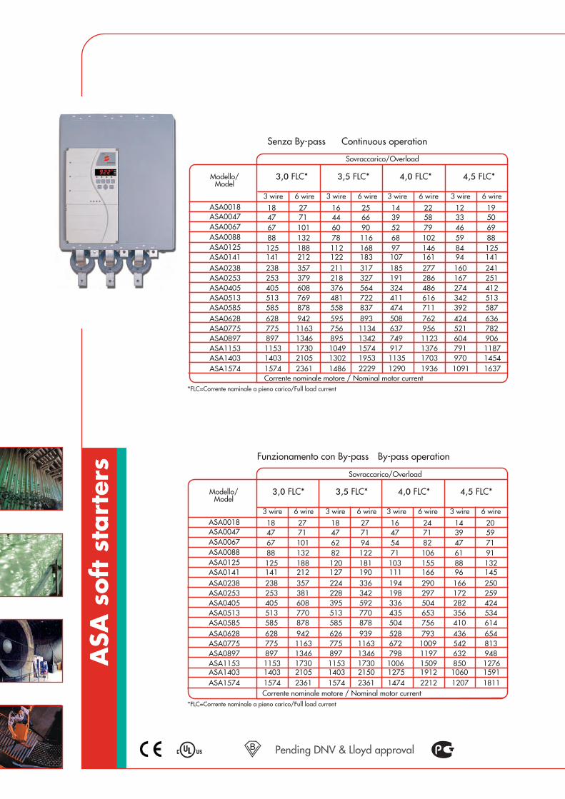
ASA
soft
sta
rter
s
Pending DNV & Lloyd approvalB
Modello/Model
ASA0141
ASA0405ASA0513ASA0585ASA0628ASA0775ASA0897ASA1153ASA1403ASA1574
ASA0253
ASA0018
ASA0238
ASA0047ASA0067ASA0088ASA0125
By-pass operationFunzionamento con By-pass
Modello/Model
ASA0141
ASA0405ASA0513ASA0585ASA0628ASA0775ASA0897ASA1153ASA1403ASA1574
ASA0253
ASA0018
ASA0238
ASA0047ASA0067ASA0088ASA0125
Continuous operationSenza By-pass
3 wire 6 wire 3 wire 6 wire 3 wire 6 wire 3 wire 6 wire
3,0 FLC* 3,5 FLC* 4,0 FLC* 4,5 FLC*
18 27 16 25 14 2239 58
6879102146
253 379 218 327 191
161
486513 769 481 722 411
286277
616585 878 558 837 474 711628 942 595 893 508 762775 1163 756 1134 637 956897 1346 895 1342 749 11231153 1730 1049 1574 917 13761403 2105 1302 1953 1135 17031574 2361 1486 2229 1290 1936
52
125 188 112 168 97141 212 122 183 107238 357 211 317 185
405 608 376 564 324
47 71 44 6667 101 60 9088 132 78 116
12 1933 50
596988125
167
141
412342
251241
513392 587424 636521 782604 906791 1187970 14541091 1637
46
8494160
274
Corrente nominale motore / Nominal motor current
Sovraccarico/Overload
3 wire 6 wire 3 wire 6 wire 3 wire 6 wire 3 wire 6 wire
3,0 FLC* 3,5 FLC* 4,0 FLC* 4,5 FLC*
18 27 18 27 16 2447 71
7182106155
253 381 228 342 198
166
504513 770 513 770 435
297290
653585 878 585 878 504 756628 942 626 939 528 793775 1163 775 1163 672 1009897 1346 897 1346 798 11971153 1730 1153 1730 1006 15091403 2105 1403 2150 1275 19121574 2361 1574 2361 1474 2212
54
125 188 120 181 103141 212 127 190 111238 357 224 336 194
405 608 395 592 336
47 71 47 7167 101 62 9488 132 82 122
14 2039 59
617191132
172
145
424356
259250
534410 614436 654542 813632 948850 12761060 15911207 1811
47
8896166
282
Corrente nominale motore / Nominal motor current
Sovraccarico/Overload
*FLC=Corrente nominale a pieno carico/Full load current
*FLC=Corrente nominale a pieno carico/Full load current

ELETTRONICASANTERNO
37
ModelsPesi/
Weight(Kg)
Dimensioni LxAxPDimensions WxHxD
(mm)
ASA067-0125
ASA0141-0238
ASA1153-1574
185x380x250
270x425x275
574x855x353
7
17,5
120
185x380x180ASA0018-0047
42ASA0405-0897 430x690x294
6
23ASA0253 390x425x275
IP00/NEMA 0
IP42 or IP54/ NEMA 1 or NEMA 12
Queste tabelle sono da ritenersi indicative. La reale corrente di spunto richesta è una carattestica intrinseca del motore e della macchina. Per dimensionamenti precisi vedere l’esempioThe above tables are intended as a guide only. Individual machine and motor characteristics will determine the actual start current requirements. For accurate designing see the example
OVERLOAD CHOICESCELTA DEL SOVRACCARICO
4,5
Mola-Grinder
Centralina idraulica-Hydraulic power pack
Mulino-Mill
Mulino a sfere-Mill ball
Mulino a martelli-Mill hammer
Mulino rotativi-Mill roller
Miscelatore-Mixer
Pallettizzatore-Palletiser
Piallatrici-Planer
Pressa-Press
Pompa sommersa-Bore pump
Pompa centrifuga-Centrifugal pump
Pompa a sfasamento positivo-Positive displacement pump
Pompa fanghi-Slurry pump
Spappolatore-Pulper
Tavolo rotativo-Rotary table
Levigatrice-Sander
Sega a nastro-Bandsaw
Sega circolare-Circular saw
Separatore-Separator
Trinciatrice-Shredder
Affettatrice-Slicer
Bottale-Tumbler
43 3,5
Ventilatore ad alta pressione-Fan high pressure
�
�
�
�
�
�
�
�
�
�
�
�
�
�
�
�
�
�
�
�
�
�
�
�
Settori d’impiego/Applications Sovraccarico/Overload (IST)
4,5
Agitatore-Agitator
Atomizzatore-Atomizer
Lava bottiglie-Bottle washer
Centrifuga-Centrifuge
Sminuzzatore-Chipper
Compressore a pistoni a carico-Loaded piston compressor
Compressore a pistoni a vuoto-Unloaded piston compressor
Compressore a vite a carico-Screw compressor loaded
Compressore a vite a vuoto-Screw compressor unloaded
Nastro di trasporto-Conveyor belt
Rulliera-Conveyor roller
Coclea-Conveyor screw
Frantumatore a cono-Crusher cone
Frantumatore a mascella-Crusher jaw
Frantumatore rotativo-Crusher rotary
Frantumatore ad impatto verticale-Crusher vertical impact
Scortecciatore-Debarker
Essiccatore-Dryer
Aspiratore-Dust collector
Taglierina-Edger
Ventilatore assiale con smorzatore-Fan axial damped
Ventilatore assiale non smorzato-Fan axial undamped
Ventilatore centrifugo con smorzatore-Fan centrifugal damped
Ventilatore centrifugo non smorzato-Fan centrifugal undamped
43 3,5
�
�
�
�
�
�
�
�
�
�
�
�
�
�
�
�
�
�
�
�
�
�
�
Settori d’impiego/Applications Sovraccarico/Overload (IST)
�
ηTipo motore/Motor type
Pn
kW CV
nN MN
Nm
In a 400V
(A) % Weight
Peso
P.F.
cosfi
45 60MA 225 M 4 80291,5 30992,30,881475
RPM
400
/ 69
0Vac Is
In
Ts
Tn
Tmax
Tn
2,32,27,2
Es: Pompa sommersa con motore da 45kW, 4 poli Ex: 45kW, 4 pole motor for bore pump
Ts
Tnx Mn
TL Is
Inx
2,2 x 291,5
987,2x= = 2,8
TL - Coppia massima di spunto richiesta dal carico/Maximum starting torque requested by load= 98Nm
IST - Sovraccarico di corrente rispetto alla nominale/Overload value
IST=
Informazioni tecniche più dettagliate sono disponibili su www.elettronicasanterno.it /More technical information available at www.elettronicasanterno.it
Compressore centrifugo-Centrifugal compressor �

AVVIATORI STATICI SOFT-START/STOP DI MEDIA TENSIONE
SOFT START/STOP STATIC STARTERS MEDIUM VOLTAGE
2 years warranty
Range 80A a 321A
Power supply voltage range,2300Vac - 11000Vac
Input frequency 50 - 60Hz
Full compatibility withteleservice software “REMOTEDRIVE” on internet
2 anni di garanzia
Gamma 80A a 321A
Tensioni d'alimentazioneda 2300Vca a 11000Vca
Frequenza 50 - 60Hz
Compatibile con software diteleassistenza,
“REMOTE DRIVE” via internet R
EMOTE
D R I VE
R
E TE
D R I VE
2WAR
RANTY
Y
E A R
S
NEW
ASA
MV
soft
sta
rter
s
Marine pending

TECHNICAL FEATURES
Power supply from 2300Vac to 11000Vac, rated current from 80 to 321A3 types of motor starting (Constant Current, Current Ramp, Torque Control)Stopping (Coast to stop, Soft Stop, Pump control profiles, Auto Stop)Allowed overload from 350% to 500% of the nominal currentSTAND ALONE MODEL IP00 – Nema 0 protection degree(IP54 - Nema 12 for control unit)CABINET MODEL from IP21 up to IP54 protection degreeClass A EMCOperating temperature -10÷+50°CHumidity from 5% to 95%Pollution degree 3Protection: Under/ Overvoltage, Supply Frequency, Phase Sequence,Shorted SCR, Motor Overload (Thermal Model), InstantaneousOvercurrent, Ground Fault, Undercurrent, Current Imbalance, MotorThermistor, Excess Start Time, Power Circuit, Auxiliary TripInterface: 5 Remote Control Inputs (3 x fixed, 2 x programmable),6 Relay Outputs (3 fixed, 3 x programmable), Analog Output(1 x programmable), Serial Output (1 x RS485)Human Interface: Multi-Language LDC Display 20 characters 2 line,Start-Stop-Reset-Local/Remote keys, Starter Status LEDs, Event Log(99 positions, date and time stamped), Trip Log (8 positions, dateand time stamped), Counters (starts, hours-run, kWh), Metering(current, voltage, power factor, kWh), User Programmable MeteringScreen, Multi-Level Password Protection
OPTIONS
RTD InterfaceModbus RTU InterfaceProfibus InterfaceDeviceNet InterfaceSynchronous Motor ControlPC Software Remote DriveRemote OperatorControl supply transformer
ELETTRONICASANTERNO
39
Informazioni tecniche più dettagliate sono disponibili su www.elettronicasanterno.it /More technical information available at www.elettronicasanterno.it
CARATTERISTICHE TECNICHE
Alimentazione da 2300Vac a 11000Vac, corrente nominale da 80 a 321A3 tipi di avviamento (Corrente costante, rampa di corrente, controllo di coppia)
Arresto (fermata in flle, soft stop, fermata pompe, fermata automatica)Sovraccarico ammesso dal 350% al 500% della corrente nominale
Grado di protezione IP00 – Nema 0 in versione stand alone(IP54 –Nema 12 per l’unità di controllo).
Grado di protezione da IP21 a IP54 per versione in CABINETEMC classe A
Temperatura di esercizio -10÷+50°CUmidità relativa dal 5% al 95%
Grado d’inquinamento 3Protezioni: sovra e sotto tensione, frequenza di alimentazione fuori tolleranza, sequenzafasi errata, cortocircuito SCR, sovraccarico motore (modello con termico) sovracorrenteistantanea, cortocircuito verso terra, sottocorrente, correnti sbilanciate, PTC motore,
eccessivi tempo di avviamento, allarme circuito di potenza, allarme ausiliari.Interfaccia: 5 ingressi digitali (3 fissi, 2 programmabili), 5 uscitè a
relè (3 fisse, 3 programmabili), 1 uscita analogica (programmabile),seriale RS485
Interfaccia operatore: Display LCD multilingue 2 linee 20 caratteri, pulsantidi Start-Stop-Reset-Locale/Remoto, led di segnalazione, storico eventi (ultimi99 eventi con data e ora), storico allarmi (ultimi 8 allarmi con data e ora),contatore (numero avviamenti, ore di funzionamento, kWh), misure (corrente,
tensione, fattore di potenza, kWh), programmazione delle misurevisualizzabili, Multi-level password di protezione
OPZIONI
Interfaccia per sensori di temperatura esternaInterfaccia Modbus RTU
Interfaccia ProfibusInterfaccia DeviceNet
Controllo per motori sincroniPC Software Remote Drive
Tastiera remotaTrasformatore alimentazione unità di controllo
12060321
Supply Voltage02 = 2300 VAC 50 / 60 Hz03 = 3300 VAC 50 / 60 Hz04 = 4160 VAC 50 / 60 Hz06 = 6600 VAC 50 / 60 Hz07 = 7200 VAC 50 / 60 Hz11 = 11000 VAC 50 / 60 Hz
Control Supply Voltage12 = 110 VAC & 230 VAC
ASAMV
Current Rating0080 = 80 A @ AC53b 4-20 : 17800159 = 159 A @ AC53b 4-20 : 17800230 = 230 A @ AC53b 4-20 : 17800321 = 321 A @ AC53b 4-20 : 1780

ASA
MV
soft
sta
rter
s
Due avviamenti per ora / Two starts per hour
Range di corrente / Current ratings
3.5-15:1785 4.0-20:1780 4.0-30:1770 5.0-30:1770 5.0-60:1740
40 °C 50 °C 40 °C 50 °C 40 °C 50 °C 40 °C 50 °C 40 °C 50 °C
ASAMV -0080-xx-xx 96 91 80 74 72 66 59 55 46 42
ASAMV -0159-xx-xx 190 177 159 147 143 132 117 109 91 84
ASAMV -0230-xx-xx 282 261 230 213 201 185 165 152 121 111
ASAMV -0321-xx-xx 393 363 321 296 279 257 229 211 168 154
Corrente nominale motore/Nominal motor current
4.0-20:1180 4.0-30:1170 5.0-30:1170 5.0-60:1140
40 °C 50 °C 40 °C 50 °C 40 °C 50 °C 40 °C 50 °C
ASAMV -0080-xx-xx 73 68 65 60 53 49 40 37
ASAMV -0159-xx-xx 146 135 129 119 106 98 79 73
ASAMV -0230-xx-xx 207 190 175 162 144 132 101 93
ASAMV -0321-xx-xx 288 265 244 225 200 184 141 129
Corrente nominale motore/Nominal motor current
4.0-20:880 4.0-30:870 5.0-30:870 5.0-60:840
40 °C 50 °C 40 °C 50 °C 40 °C 50 °C 40 °C 50 °C
ASAMV -0080-xx-xx 68 63 59 54 48 45 35 33
ASAMV -0159-xx-xx 136 125 117 108 96 89 70 65
ASAMV -0230-xx-xx 188 173 157 144 129 118 88 81
ASAMV -0321-xx-xx 262 241 218 200 179 164 122 112
FLC Corrente nominale motore/FLC Nominal motor current
Tre avviamenti per ora / Three starts per hour
Quattro avviamenti per ora / Four starts per hour
Marine pending

ELETTRONICASANTERNO
41
Informazioni tecniche più dettagliate sono disponibili su www.elettronicasanterno.it /More technical information available at www.elettronicasanterno.it
STAND ALONE MODELIP00 – Nema 0
Dimensioni LxHxPDimensions WxHxD
(mm)
Weight(kg)
ASAMV-xxxx-02-xx
669 772 667 165ASAMV-xxxx-03-xx
ASAMV-xxxx-04-xx
ASAMV-xxxx-06-xx875 832 817 217
ASAMV-xxxx-07-xx
ASAMV-xxxx-11-xx Su richiesta/On request
ASAMV Control unit 340 220 54 2,1
AC53b Configurazione categoria d’utilizzo / Utilisation Category Format
Start Current (multiple of FLC)
Off Time (seconds)
80 A : AC-53b 4-20 : 1780
Start Current Rating (amperes)
Start Time (seconds)
Corrente a pieno carico del soft starterThe full load current rating of the soft starter
Allowed overloadSovraccarico ammesso
Masimo tempo di avviamentoThe maximum available start time
Minimo tempo che deve trascorrere tra la fine e l’inizio del primo avviamentoThe minimum allowable time between the end of one start and the beginningof the next start
Starter Current Rating
Start Current
Start Time
Off Time
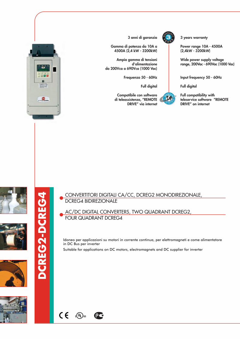
DCREG
2-D
CREG
4 CONVERTITORI DIGITALI CA/CC, DCREG2 MONODIREZIONALE,DCREG4 BIDIREZIONALE
AC/DC DIGITAL CONVERTERS, TWO QUADRANT DCREG2,FOUR QUADRANT DCREG4
3 years warranty
Power range 10A - 4500A(2,4kW - 3200kW)
Wide power supply voltagerange, 200Vac - 690Vac (1000 Vac)
Input frequency 50 - 60Hz
Full digital
Full compatibility withteleservice software “REMOTEDRIVE” on internet
3 anni di garanzia
Gamma di potenza da 10A a4500A (2,4 kW - 3200kW)
Ampia gamma di tensionid'alimentazione
da 200Vca a 690Vca (1000 Vac)
Frequenza 50 - 60Hz
Full digital
Compatibile con software di teleassistenza, “REMOTE
DRIVE” via internet
R
EMOTE
D R I VE
R
E TE
D R I VE
3WAR
RANTY
Y
E A R
S
Idoneo per applicazioni su motori in corrente continua, per elettromagneti e come alimentatorein DC Bus per inverter
Suitable for applications on DC motors, electromagnets and DC supplier for inverter

TECHNICAL FEATURES
Self-calibration of current and speed(Reduce possibility of error and installation time)Self-calibration of field (Reduces possibility of error and installation time)Internal field converter (for operation in constant torque or power)Field economy (reduce the field current when motor is stopped)Field boost (increase torque on motor start)Predictive control (increase the dynamic response of the motor)Integrated multimeterSpeed multiramps“S” rampsDouble speed ring with automatic adaptationFeedback from tachometric dynamo, from encoder and armatureAutomatic switching of the feedback in armature in the event of breakdownof dynamo/encoder (higher safety operation)Control of the current limit in steps or hyperbolic7 levels of speedJOG commandsAuto-reset alarmsIntegrated digital potentiometerTimer on digital outputsLocal control from keyboardInsensitivity to phase-rotation ( for easy connection)Independent supplies to control and power8 programmable inputs4 programmable analog inputs 0-±10Vdc, 0(4)-20mADouble encoder inputTacho input5 programmable relay outputsAuxiliary 24Vdc, ±10Vdc, 5 Vdc1 analog speed output ±10Vdc1 analog current output ±10Vdc2 programmable analog ouputs 0-±10Vdc, 0(4)-20mAEMC compliant with EN 61800-3 2nd ed.
OPTIONS
“Remote Drive” softwareKeyboardKit remote keyboard operation (5 metres)RS232/485 interfaceMODBUS RTU 115,2kbpsProfibus DP 12mbps - CanBus - Device Net etc.IP 20 kit protection degreeInput chokesKit for heatsink segregationFast fusesCU400 Clamping unit for electromagnets
CARATTERISTICHE TECNICHE
Autotaratura di corrente e velocità(Riduce possibilità di errori e i tempi di installazione)
Autotaratura di campo (Riduce possibilità di errori e i tempi di installazione)Deflussatore integrato (per funzionamento a coppia o potenza costante)
Economy (riduce la corrente di campo quando il motore è fermo)Boost di campo (aumenta la coppia del motore alla partenza)Controllo predittivo (aumenta la risposta dinamica del motore)
Tester multifunzione integratoMultirampe di velocità
Rampe a “S”Doppio anello di velocità con adattamento automatico
Retroazione da armatura da dinamo tachimetrica e da encoderCommutazione automatica della retroazione in armatura in caso di rottura
dinamo/encoder (maggiore sicurezza di funzionamento motore)Controllo del limite di corrente a gradino o iperbolico
7 livelli di velocitàComandi di JOG
Autoreset allarmi (continuità di funzionamento)Potenziometro digitale integrato
Timer su uscite digitaliControllo locale da tastiera
Insensibilità senso ciclico (semplifica il collegamento all’impianto)Alimentazioni indipendenti tra controllo e potenza
8 ingressi digitali programmabili4 ingressi analogici programmabili 0-±10Vdc, 0(4)-20mA
Doppio ingresso encoderIngresso dinamo tachimetrica
5 uscite configurabili a relèTensioni ausiliarie 24Vdc, ±10Vdc, 5Vdc
1 uscita analogica di velocita ±10Vdc1 uscita analogica di corrente ±10Vdc
2 uscite analogiche configurabili 0-±10Vdc, 0(4)-20mAConforme alla norma EMC EN61800-3 ed. 2
OPZIONI
Software “Remote Drive”Tastiera di programmazione
Kit remotizzazione tastiera (5 metri)Interfaccia RS232/485
MODBUS RTU 115,2kbpsProfibus DP 12mbps - CanBus - Device Net ecc.
Kit protezione IP20Induttanze di ingresso
Kit montaggio passanteFusibili extra rapidi
Unità Clamping CU400 per elettromagneti
ELETTRONICASANTERNO
43
Informazioni tecniche più dettagliate sono disponibili su www.elettronicasanterno.it /More technical information available at www.elettronicasanterno.it
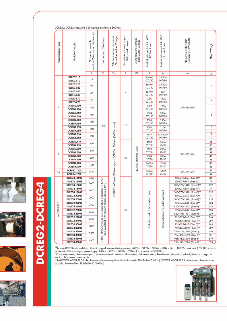
DCREG
2-D
CREG
4
1) La serie DCREG è disponibile in differenti range di tensione d'alimentazione: 440Vac - 500Vac - 600Vac - 690Vac (fino a 1000Vac su richiesta) /DCREG series isavailable in different range of power supply: 440Vac - 500Vac - 600Vac - 690Vac (on request up to 1000 Vac)* Corrente nominale, dimensione e pesi possono cambiare in funzione della tensione di alimentazione. / Rated current, dimension and weight can be changed infunction of the power power supply.** Nel DCREG MODULARE.S, alle dimesioni indicate va aggiunta l'unità di controllo 214x265x440 (LxPxH) / DCREG MODULARE.S, at the shown dimensins mustbe added the control unit 214x265x440 (WxDxH)
DCREG2-DCREG4 tensioni d’alimentazione fino a 500Vac 1)
A % Vdc A Vdc A A mm kg
1
DCREG2.1010
150%
5
35-40A00T/80
35-40A00T/80
214x264x440
13
DCREG4.10DCREG2.20
2035-40A00T/80
35-40A00T/80DCREG4.20
DCREG2.4040
35-40A00T/80
50A00T/80DCREG4.40
DCREG2.7070
63A00T/80
100A00T/80
14DCREG4.70DCREG2.100
100100A
00T/80125A
00T/80
15
DCREG4.100DCREG2.150
150
15
160A00T/80
200A00T/80DCREG4.150
DCREG2.180180
200A00T/80
250A00T/80DCREG4.180
DCREG2.250250
250A00T/80
315A00T/80
18DCREG4.250 19DCREG2.350
350315A
00T/80375-400A
00T/8018
DCREG4.350 19
2
DCREG2.410410
35
450A2T/80
550A2T/80
333x360x596
38DCREG4.410 40DCREG2.500
500550A2T/80
700A2T/80
45DCREG4.500 48DCREG2.600
600550A2T/80
700A2T/80
45DCREG4.600 48DCREG2.900
9001000A3T/80
1000A3T/80
45DCREG4.900 48
2ADCREG2.1200
12001250A3T/80
1250A3T/80
333x453x68551
DCREG4.1200 54
DCREG4.1400S 1400
35
500x275x860 (Size F)** 84DCREG2.1600S
1600500x275x860 (Size A)** 79
DCREG4.1600S 500x375x1410 (Size G)** 159DCREG2.1800S
1800500x275x860 (Size A)** 79
DCREG4.1800S 500x375x1410 (Size G)** 159DCREG2.2000S
2000500x275x860 (Size A)** 79
DCREG4.2000S 500x375x1410 (Size G)** 159DCREG2.2300S
2300620x360x884 (Size B)** 124
DCREG4.2300S 620x495x1434 (Size H)** 229DCREG2.2500S
2500620x360x884 (Size B)** 124
DCREG4.2500S 620x495x1434 (Size H)** 229DCREG2.2700S
2700712x395x945 (Size C)** 164
DCREG4.2700S 712x495x1505 (Size I)** 289DCREG2.3000S
3000712x395x945 (Size C)** 164
DCREG4.3000S 712x495x1505 (Size I)** 289DCREG2.3500S
3500784x415x1110 (Size D)** 206
DCREG4.3500S 784x460x1790 (Size J)** 331DCREG2.4500S
4500968x482x1250 (Size E)** 319
DCREG4.4500S 988x543x2070 (Size K)** 624
*Gra
ndez
za/*
Size
*Mod
ello
/*M
odel
*Cor
rent
e no
min
ale
amat
ura/
*Arm
atur
e ra
ted
curr
ent
Sovr
acca
rico/
Ove
rload
*Usc
ita te
nsio
ne a
rmat
ura/
*Arm
atur
e ou
tput
Vol
tage
Cor
rent
e no
min
ale
cam
po/
Fiel
d ra
ted
curr
ent
Usc
ita te
nsio
ne c
ampo
/Fi
eld
outp
ut v
olta
ge
Fusi
bili
extra
rapi
di la
to A
C/
AC
Fas
t fus
es
Fusi
bili
extra
rapi
di la
to D
C/
DC
Fas
t fus
es
*Dim
ensi
oni (
LxPx
H)/
*Dim
ensi
ons
(WxD
xH)
*Pes
i/*W
eigh
t
MO
DU
LARE
.S
125%
(150
% O
verlo
ad c
on te
mpe
ratu
ra d
issi
pato
re <
40°
C/
150%
Ove
rload
with
hea
tsink
tem
eper
atur
e <
40°C
Incl
usi a
bor
do /
Incl
uded
on
bora
d
Incl
usi a
bor
do /
Incl
uded
on
bora
d
DC
REG
2: 6
00m
ax (5
00Va
c in
put)
- D
CRE
G4:
520
max
(500
Vac
inpu
t)
425m
ax (5
00Va
c in
put)
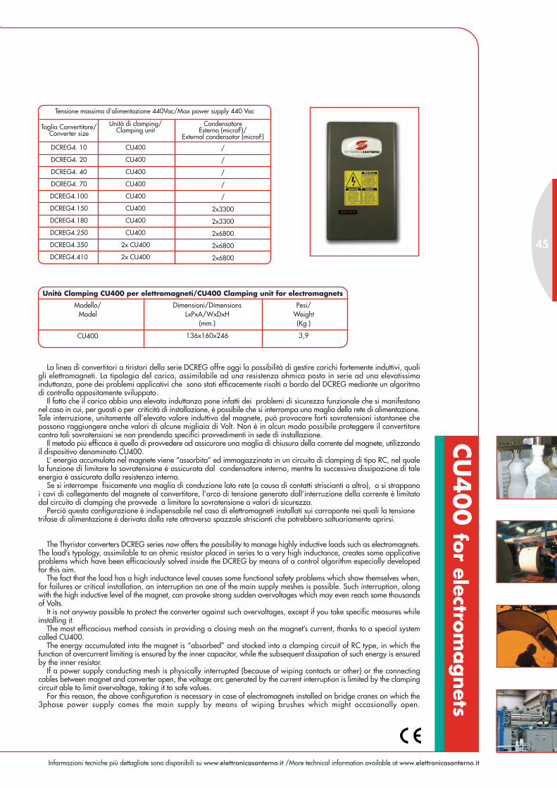
Informazioni tecniche più dettagliate sono disponibili su www.elettronicasanterno.it /More technical information available at www.elettronicasanterno.it
La linea di convertitori a tiristori della serie DCREG offre oggi la possibilità di gestire carichi fortemente induttivi, qualigli elettromagneti. La tipologia del carico, assimilabile ad una resistenza ohmica posta in serie ad una elevatissimainduttanza, pone dei problemi applicativi che sono stati efficacemente risolti a bordo del DCREG mediante un algoritmodi controllo appositamente sviluppato.
Il fatto che il carico abbia una elevata induttanza pone infatti dei problemi di sicurezza funzionale che si manifestanonel caso in cui, per guasti o per criticità di installazione, è possibile che si interrompa una maglia della rete di alimentazione.Tale interruzione, unitamente all’elevato valore induttivo del magnete, può provocare forti sovratensioni istantanee chepossono raggiungere anche valori di alcune migliaia di Volt. Non è in alcun modo possibile proteggere il convertitorecontro tali sovratensioni se non prendendo specifici provvedimenti in sede di installazione.
Il metodo più efficace è quello di provvedere ad assicurare una maglia di chiusura della corrente del magnete, utilizzandoil dispositivo denominato CU400.
L’ energia accumulata nel magnete viene “assorbita” ed immagazzinata in un circuito di clamping di tipo RC, nel qualela funzione di limitare la sovratensione è assicurata dal condensatore interno, mentre la successiva dissipazione di taleenergia è assicurata dalla resistenza interna.
Se si interrompe fisicamente una maglia di conduzione lato rete (a causa di contatti striscianti o altro), o si strappanoi cavi di collegamento del magnete al convertitore, l’arco di tensione generato dall’interruzione della corrente è limitatodal circuito di clamping che provvede a limitare la sovratensione a valori di sicurezza.
Perciò questa configurazione è indispensabile nel caso di elettromagneti installati sui carroponte nei quali la tensionetrifase di alimentazione è derivata dalla rete attraverso spazzole striscianti che potrebbero saltuariamente aprirsi.
The Thyristor converters DCREG series now offers the possibility to manage highly inductive loads such as electromagnets.The load’s typology, assimilable to an ohmic resistor placed in series to a very high inductance, creates some applicativeproblems which have been efficaciously solved inside the DCREG by means of a control algorithm especially developedfor this aim.
The fact that the load has a high inductance level causes some functional safety problems which show themselves when,for failures or critical installation, an interruption on one of the main supply meshes is possible. Such interruption, alongwith the high inductive level of the magnet, can provoke strong sudden overvoltages which may even reach some thousandsof Volts.
It is not anyway possible to protect the converter against such overvoltages, except if you take specific measures whileinstalling it.
The most efficacious method consists in providing a closing mesh on the magnet’s current, thanks to a special systemcalled CU400.
The energy accumulated into the magnet is “absorbed” and stocked into a clamping circuit of RC type, in which thefunction of overcurrent limiting is ensured by the inner capacitor, while the subsequent dissipation of such energy is ensuredby the inner resistor.
If a power supply conducting mesh is physically interrupted (because of wiping contacts or other) or the connectingcables between magnet and converter open, the voltage arc generated by the current interruption is limited by the clampingcircuit able to limit overvoltage, taking it to safe values.
For this reason, the above configuration is necessary in case of electromagnets installed on bridge cranes on which the3phase power supply comes the main supply by means of wiping brushes which might occasionally open.
Modello/Model
136x160x246 3,9
Pesi/Weight(Kg.)
Dimensioni/DimensionsLxPxA/WxDxH
(mm.)
CU400
Unità Clamping CU400 per elettromagneti/CU400 Clamping unit for electromagnets
Taglia Convertitore/Converter size
Unità di clamping/Clamping unit
CondensatoreEsterno (microF)/
External condensator (microF)
DCREG4. 10
DCREG4. 20
DCREG4. 40
DCREG4. 70
DCREG4.100
DCREG4.150
DCREG4.180
DCREG4.250
DCREG4.350
DCREG4.410
CU400
CU400
CU400
CU400
CU400
CU400
CU400
CU400
2x CU400
2x CU400
/
/
/
/
/
2x3300
2x3300
2x6800
2x6800
2x6800
Tensione massima d’alimentazione 440Vac/Max power supply 440 Vac
45
CU
400 fo
r electrom
agnets

REM
OTE
DRIV
E
ricezione-trasmissione-salvataggio dati, da e su PC/data reception, transmission and saving, from a PC
and onto a PC
emulatore di tastiera bordo macchina/keyboard emulator on the machine
programmazione e archiviazione parametri/parameters’ programming and storing
stampa parametri/parameters’ print
visualizzazione grafica grandezze elettriche/graphic display of electric values
data logger
aggiornamento firmware/firmware update
INTERFACCIA DI COMUNICAZIONE ESOFTWARE DI GESTIONE
Uno strumento di programmazione e diagnostica che operain ambiente Windows, per tutti i convertitori Elettronica
Santerno.Offre i seguenti strumenti:
COMMUNICATION INTERFACE ANDMANAGEMENT SOFTWARE
A programming and diagnostics utility that works Windows,for all Elettronica Santerno drives.It offers the following tools:
R
EMOTE
D R I VE
R
E TE
D R I VE
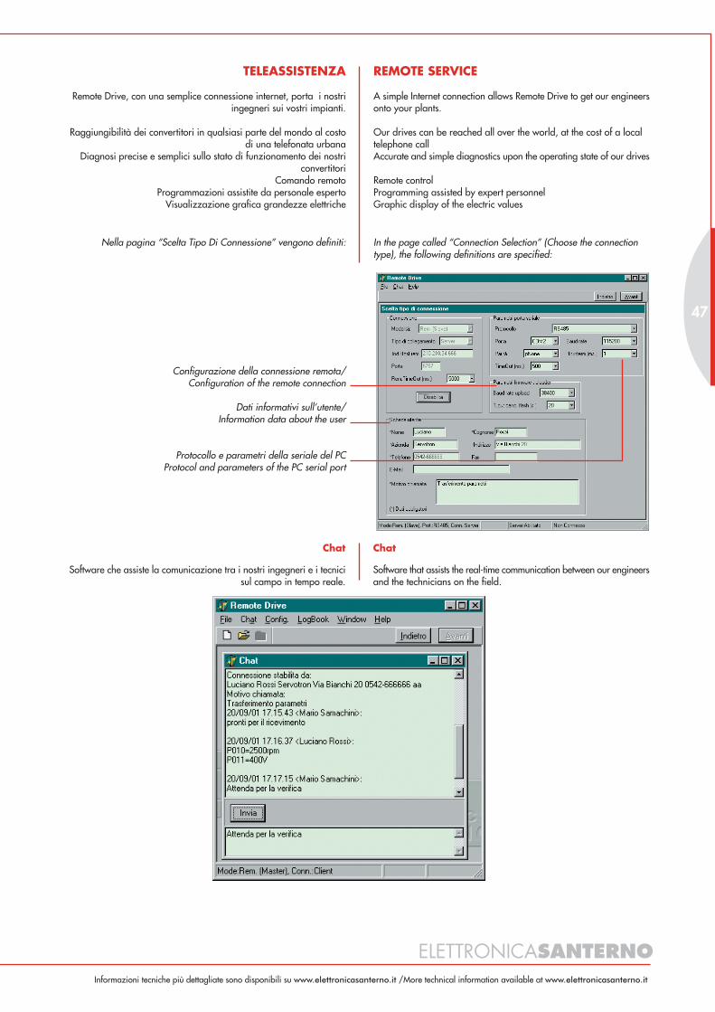
ELETTRONICASANTERNO
47
REMOTE SERVICE
A simple Internet connection allows Remote Drive to get our engineersonto your plants.
Our drives can be reached all over the world, at the cost of a localtelephone callAccurate and simple diagnostics upon the operating state of our drives
Remote controlProgramming assisted by expert personnelGraphic display of the electric values
Configurazione della connessione remota/Configuration of the remote connection
Dati informativi sull’utente/Information data about the user
Protocollo e parametri della seriale del PCProtocol and parameters of the PC serial port
Chat
Software that assists the real-time communication between our engineersand the technicians on the field.
TELEASSISTENZA
Remote Drive, con una semplice connessione internet, porta i nostriingegneri sui vostri impianti.
Raggiungibilità dei convertitori in qualsiasi parte del mondo al costodi una telefonata urbana
Diagnosi precise e semplici sullo stato di funzionamento dei nostriconvertitori
Comando remotoProgrammazioni assistite da personale esperto
Visualizzazione grafica grandezze elettriche
Chat
Software che assiste la comunicazione tra i nostri ingegneri e i tecnicisul campo in tempo reale.
Nella pagina “Scelta Tipo Di Connessione” vengono definiti: In the page called “Connection Selection” (Choose the connectiontype), the following definitions are specified:
Informazioni tecniche più dettagliate sono disponibili su www.elettronicasanterno.it /More technical information available at www.elettronicasanterno.it

DBF
200T CONVERTITORI BRUSHLESS
BRUSHLESS DRIVES
Full digital regulation(RISC 32 bit)
Three phase power supply140/240Vac
Input frequency 45 - 65Hz
Range 3 - 12A
Full-digital (RISC 32 bit)
Alimentazione trifase140/240Vca
Frequenza ingresso 45 - 65Hz
Range 3 - 12A
Serie di convertitori ideata per coprire particolarmente la fascia di applicazioni a bassa coppia.
Le dimensioni compatte e le ottime prestazioni dinamiche lo rendono ideale per una vasta gamma di applicazioni.
Brushless drive series expressly designed to cover the low torque industrial applications.
Compact sizes and high dynamic performances make it suitable for a large range of applications.
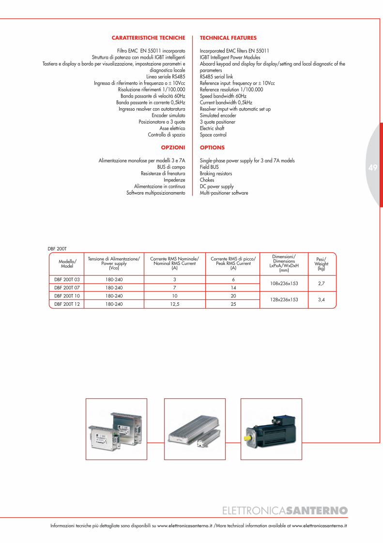
TECHNICAL FEATURES
Incorporated EMC filters EN 55011IGBT Intelligent Power ModulesAboard keypad and display for display/setting and local diagnostic of theparametersRS485 serial linkReference input: frequency or ± 10VccReference resolution 1/100.000Speed bandwidth 60HzCurrent bandwidth 0,5kHzResolver imput with automatic set upSimulated encoder3 quote positionerElectric shaftSpace control
OPTIONS
Single-phase power supply for 3 and 7A modelsField BUSBraking resistorsChokesDC power supplyMulti-positioner software
CARATTERISTICHE TECNICHE
Filtro EMC EN 55011 incorporatoStruttura di potenza con moduli IGBT intelligenti
Tastiera e display a bordo per visualizzazione, impostazione parametri ediagnostica locale
Linea seriale RS485Ingresso di riferimento in frequenza o ± 10Vcc
Risoluzione riferimenti 1/100.000Banda passante di velocità 60Hz
Banda passante in corrente 0,5kHzIngresso resolver con autotaratura
Encoder simulatoPosizionatore a 3 quote
Asse elettricoControllo di spazio
OPZIONI
Alimentazione monofase per modelli 3 e 7ABUS di campo
Resistenze di frenaturaImpedenze
Alimentazione in continuaSoftware multiposizionamento
ELETTRONICASANTERNO
49
Modello/Model
Tensione di Alimentazione/Power supply
(Vca)
Corrente RMS Nominale/Nominal RMS Current
(A)
Corrente RMS di picco/Peak RMS Current
(A)
DBF 200T 03 180-240
DBF 200T 07 180-240
DBF 200T 10 180-240 10
DBF 200T 12 180-240 12,5
3
7
20
25
6
14
128x236x153
108x236x153
3,4
2,7
Dimensioni/Dimensions
LxPxA/WxDxH(mm)
Pesi/Weight
(kg)
DBF 200T
Informazioni tecniche più dettagliate sono disponibili su www.elettronicasanterno.it /More technical information available at www.elettronicasanterno.it
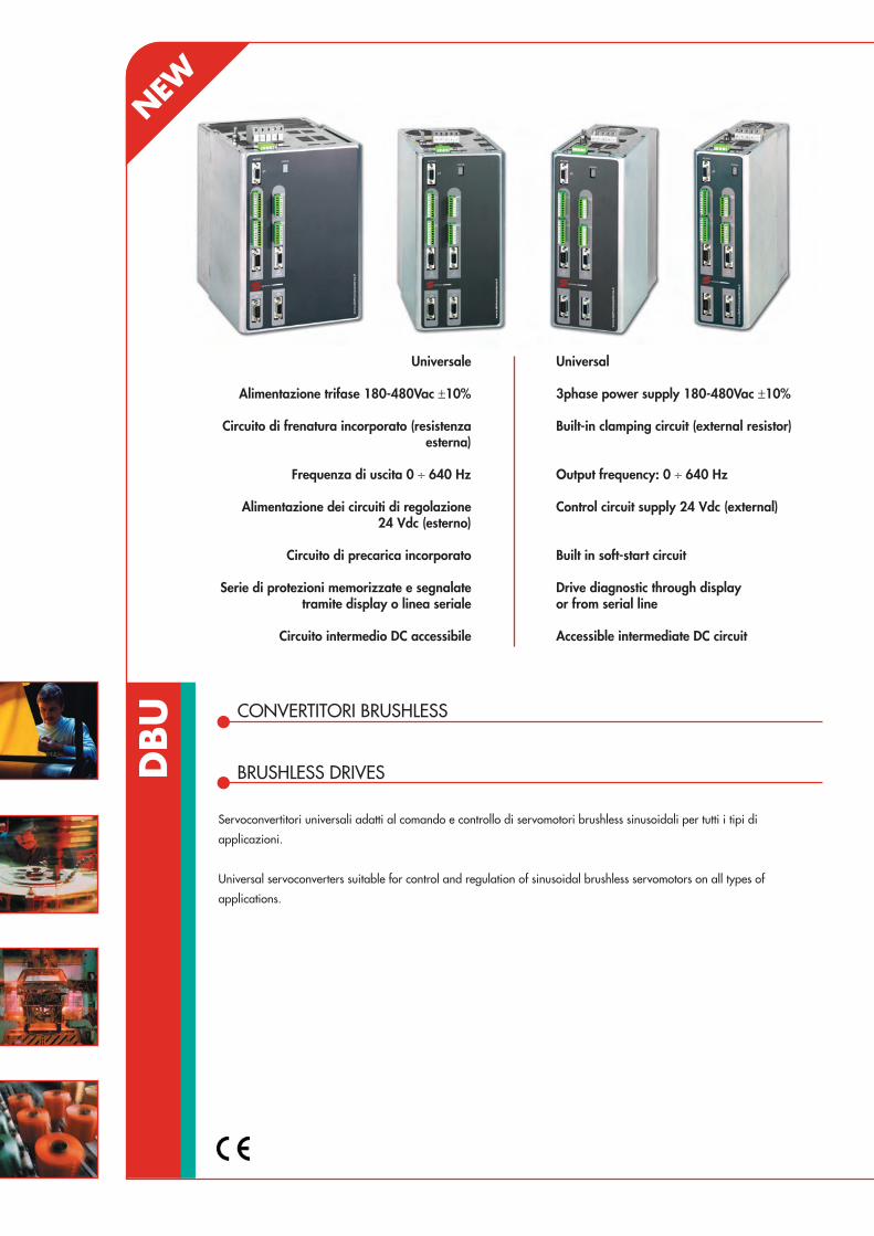
DBU CONVERTITORI BRUSHLESS
BRUSHLESS DRIVES
Universal
3phase power supply 180-480Vac ±10%
Built-in clamping circuit (external resistor)
Output frequency: 0 ÷ 640 Hz
Control circuit supply 24 Vdc (external)
Built in soft-start circuit
Drive diagnostic through displayor from serial line
Accessible intermediate DC circuit
Servoconvertitori universali adatti al comando e controllo di servomotori brushless sinusoidali per tutti i tipi di
applicazioni.
Universal servoconverters suitable for control and regulation of sinusoidal brushless servomotors on all types of
applications.
Universale
Alimentazione trifase 180-480Vac ±10%
Circuito di frenatura incorporato (resistenzaesterna)
Frequenza di uscita 0 ÷ 640 Hz
Alimentazione dei circuiti di regolazione24 Vdc (esterno)
Circuito di precarica incorporato
Serie di protezioni memorizzate e segnalatetramite display o linea seriale
Circuito intermedio DC accessibile
NEW

TECHNICAL FEATURES
Full digital regulationIndependent ramps in the 4 quadrants8 opto isolated configurable digital inputs3 programmable speed references (jog)Inputs for speed reference:- analog ±10 V (16 bit)- digital: from remote keypad or RS 485 serial line- frequency (encoder-like or frequency and up/down)Inputs for torque and current limit references:- analog ±10 V- digital: from remote keypad or serial line4 opto isolated digital outputs2 programmable analog outputs1 analog output for speed monitoring
INTEGRATED FUNCTIONS
Unique softwareResolver auto phasingCurrent loop gain automatic calibration accordingto motor inductance (motor auto tuning)Resolver resolution self-adjustment to maximizeprecision in the whole speed rangeConfigurable simulated encoder output from 64 to4096 ppr (line driver)Monitor software under Windows for parameterssetting and monitoringProgrammable profilesElectrical gearing and master/slave functionMultipositioner: 12 full programmable positionsDigital potentiometer for setting speed ratio inmaster/slave functionStep motor function with position loop controlRS485/ RS232 serial interface with Modbus protocol(baud rate 9.600 ÷ 115.200)Separate power supply for the IGBT drivers (safetystop function EN 954-1) and the regulation (24Vdc compulsory)
OPTIONS
CAN BUS interface (can open compatible)PROFIBUS DP interfaceOpto isolated simulated encoder outputRS232 / 485 adapter for PCRemote keypad for drive parameters setting and monitoringClamping resistorsExternal filters
CARATTERISTICHE TECNICHE
Regolazione full digitalRampe indipendenti nei 4 quadranti
8 ingressi digitali optoisolati, configurabili3 riferimenti di velocità jog programmabili
Ingressi per i riferimenti di velocità:- analogico ±10V (16 bit)
- digitale: da tastierino o da linea seriale RS 485- in frequenza (in quadratura o frequenza e segno)
Ingressi per i riferimenti di coppia e limite di corrente:- analogico ±10V
- digitale: da tastierino o da linea seriale RS 4854 uscite digitali optoisolate configurabili
2 uscite analogiche programmabili1 uscita analogica per monitorare la velocità
FUNZIONI INTEGRATE
Software UnicoAutoapprendimento della fasatura resolver
Calibrazione automatica del guadagno dell’anello di corrente in funzionedell’induttanza del motore (autotuning motore).
Cambio automatico della risoluzione del resolver in funzione della velocità,per ottimizzare ed ottenere la massima precisione ad ogni velocità
Uscita encoder simulato configurabile da 64 a 4096 imp./ giro (line driver)SW di supervisione per PC, con funzione oscilloscopio elettronico per una
facile messa in servizio e diagnostica drive,in ambiente Windows
Possibilità di avere delle velocità programmabiliAsse elettrico con funzioni master / slave
Multiposizionatore a 12 posizioni programmabiliFunzione potenziometro digitale per impostazione
rapporto di velocità in asse elettricoFunzione tipo step motor con anello di spazio
Porta seriale RS 232 e RS 485 (protocollo modbus)(baud rate 9.600 ÷ 115.200)
Alimentazione separata dei pilotaggi degli igbt (safetystop function EN 954-1) e della regolazione (24 Vdc obbligatorio)
OPZIONI
Scheda di comunicazione CAN BUS (can open)Scheda di comunicazione PROFIBUS DPAlimentazione esterna encoder simulato
Convertitore RS232 / 485 per connessione a PCTastierino remoto per impostazione parametri del drive
Resistenza di frenaturaFiltri esterni
ELETTRONICASANTERNO
51
Modello/Model
Tensione di Alimentazione/Power supply
(Vac)
Corrente RMS Nominale/Nominal RMS Current
(A)
Corrente RMS di picco/Peak RMS Current
(A)
DBU 03 180-480 Vac
DBU 07 180-480 Vac
DBU 12 180-480 Vac 12
DBU 15 180-480 Vac 15
3
7
24
30
6
14
134x240x310
86x240x310
Dimensioni/Dimensions
LxPxA/WxDxH(mm)
Pesi/Weight
(kg)
DBU 22
DBU 32
DBU 40
180-480 Vac
180-480 Vac
180-480 Vac
22
32
40
44
64
80
4,5
4,5
3,5
3,5
5,5
9
9190x240x310
DBU
Informazioni tecniche più dettagliate sono disponibili su www.elettronicasanterno.it /More technical information available at www.elettronicasanterno.it
113x240x310

ESB SERVOMOTORI BRUSHLESS A MAGNETI PERMANENTI
PERMANENT MAGNET BRUSHLESS SERVOMOTORS
Sinusoidal B.E.M.F.
Interchangeability with themost common servomotorspresently on the market
Low moment of inertiaresulting in high accelerationsand decelerations
High overload capacity
Low torque cogging
I servomotori brushless a magneti permanenti derivano dalle esigenze sempre più spinte dell'automazione industriale
che necessita di sistemi a sempre più elevate prestazioni e affidabilità con ridotta manutenzione. Questa serie di
servomotori utilizza magneti dell'ultima generazione in neodimio-ferro-boro.
The brushless servomotors with permanent magnets are designed to meet the more and more demanding needs
of industrial automation with quite high-performances and reliable systems and little maintenance required. This
generation series of servomotors uses the new magnets made of neodymium, iron and boron.
F.c.e.m. Sinusoidale
Intercambiabilità con leesecuzioni più diffuse presenti
sul mercato
Ridotto momento d'inerzia conconseguenti elevate
accelerazioni e decelerazioni
Elevata capacità di sovraccarico
Bassa pendolazione di coppia
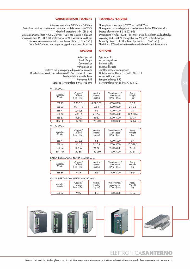
TECHNICAL FEATURES
Three phase power supply 205Vrms and 340VrmsThree-phase star winding non-accessible neutral wire, TENV executionDegree of protection IP 54 (IEC34-5)Dimensioning in F class (IEC34-1; dT=105K), even if the insulation used is of H classAssembly B5 (IEC34-7), changeable into V1 or V3 without changesNormally-closed contact for thermal protection (135°+/- 5°C)The 86 and 87 is a low inertia series used when dynamic is necessary
OPTIONS
Special shaftsAngus ring oil sealResolver cableEnhanced brakesJoint for encoder arrangementPlate for terminal board box with PG7 or 11Arranged for encoderProtection degree IP55Servoventilated version (PVAA) 103-104
CARATTERISTICHE TECNICHE
Alimentazione trifase 205Vrms e 340VrmsAvvolgimento trifase a stella senza neutro accessibile, esecuzione TENV
Grado di protezione IP54 (CEI 2-14)Dimensionamento classe F (CEI 2-3 dtmax=105k) con isolanti in classe H
Forma costruttiva B5 (CEI 2-14) trasformabile in V1 e V3 senza modificheProtezione termica con contatto normalmente chiuso (135° +/-5°C)
Serie 86-87 a bassa inerzia per maggiori prestazioni dinamiche
OPZIONI
Alberi specialiAnello AngusCavo resolver
Freni potenziatiLanterna più giunto per predisposizione encoder
Placchetta per scatola morsettiera con PG7 o 11 anziché chiusaPredisposizione encoder base
Protezione IP55Versione servoventilata (PVAA) 103-104
ELETTRONICASANTERNO
53
BASSA INERZIA/LOW INERTIA Vca 205 Vrms
Modello/Model
Coppia/Torque
(Nm) - [Tn1]
Inerzia/Inertia(kgcm2)
Velocità max/Max Speed
(RPM) - [nmax]
Peso/Weight
(kg)
ESB 86 9-25 11-31 1700-4000 18-34
BASSA INERZIA/LOW INERTIA Vca 345 Vrms
Modello/Model
Coppia/Torque
(Nm) - [Tn1]
Inerzia/Inertia(kgcm2)
Velocità max/Max Speed
(RPM) - [nmax]
Peso/Weight
(kg)
ESB 87 9-25 11-31 1500-4000 18-34
Vca 345 Vrms
Modello/Model
Coppia/Torque
(Nm) - [Tn1]
Inerzia/Inertia(kgcm2)
Velocità max/Max Speed
(RPM) - [nmax]
Peso/Weight
(kg)
ESB 44 0.9-3,8 1-5 3000-6000 3-7
ESB 64 5.2-12 7-17,5 2500-5000 10,5-18,5
ESB 84 11,5-27 26-62 2000-4000 20-35
ESB 104 32-68 120-280 1200-3000 52-84
Vca 205 Vrms
Modello/Model
Coppia/Torque
(Nm) - [Tn1]
Inerzia/Inertia(kgcm2)
Velocità max/Max Speed
(RPM) - [nmax]
Peso/Weight
(kg)
ESB 23 0,33-0,65 0,21-0,38 4000-8000 1,5-2
ESB 43 0,9-3,8 1-5 3000-6000 3-7
ESB 83
5,2-12 7-17,5 2000-5000 10,5-18,5
11,5-27 26-62 2000-4000 20-35
ESB 63
32-68 120-280 1100-3000 52-84ESB 103
ESB 33 0,6-1,15 0,5-1 4000-8000 2,4-3,8
Informazioni tecniche più dettagliate sono disponibili su www.elettronicasanterno.it /More technical information available at www.elettronicasanterno.it

ATA
- M
A MOTORI ASINCRONI
ASYNCHRONOUS MOTORS
Motore elettrico asincrono trifase normalizzato, con rotore a gabbia, chiuso, autoventilato
esternamente, classe d'isolamento F, sovratemperatura in classe “B”, grado di protezione
IP55, multitensione 380...480Vac (690Vac), multifrequenza 50/60Hz.
Asynchronous three-phase, totally enclosed, fan-cooled standard electric motor with squirrel-
cage rotors, class F insulation, class B overtemperature, IP55 protection degree, multivoltage
380...480Vac (690Vac), multifrequency 50/60Hz.

MA TECHNICAL FEATURES
MA series: IEC 63...500; 0,09...1200kW; 2,4,6,8 poles, one speedHousing IP55 size MA 63...132 of pressure-diecast aluminium-alloy withdetachable feet. MA 132M*...500 cast iron housingsRated power delivered on continuous duty (S1) maximum room temperatureof 40°C and maximum altitude 1000 m.Mounting positions: IM B3, IM B5, IM B14 and combined positions B3/B5and B3/B14Bearings made by the best bearing-manufacturers provided with greaser aboveMA 180 and selected for the specific use on electric motors (”SKF” o “NSK”)Stator-winding: made with double-coated copper-wire insulated in H class,impregnation system with high quality H class (total 180°C) resinsWindings-protection: bimetal-type thermal probes are a standard equipmenton sizes 160...500
ATA TECHNICAL FEATURES
ATA series: IEC 63...250 0,12...55 kW 2,4,6 poles, one speedHousing in IP55: sizes ATA 63...250 of pressure-diecast aluminium-alloy withdetachable feetRated power delivered on continuos duty (S1), maximum room temperatureof 40°C and maximum altitude 1000mMounting positions: IM B3, IM B5, IM B14 and combined positions B3/B5and B3/B14Bearings made by the best bearing-manufacturers and selected for the specificuse on electric motors (”SFK” o “NSK”)Stator-winding: made with double-coated copper-wire insulated in H class,impregantion system with high quality H class (total 180°C) resinsWindings-protection: bimetal-type thermal probes are a standard equipmenton sizes ATA 160...250
OPTIONS
Customized power supplyAdditional impregnation for stator windingsInsulation F/H classBearings C3 (For > radial loads)Bearings 2RS (Dust proof)Roller bearings “NU”Double flange motorCondensation drainpipe (depending on the structure)Mounting position IM B35 (B3/B5)Mounting position IM B34 (B3/B14)IP 56 degree protectionInternal heaterSelf-braker motorForced coolingEncoderMilitary connectors for EncoderApplication of hollow tachometerBimetallic thermal probe [limit value: 150 °C normal]Bimetallic thermal probe [limit value: 120 °C special]Waterproof cover
Model in
CARATTERISTICHE TECNICHE MA
Serie MA: IEC 63...500; 0,09...1200kW; 2,4,6,8 poli, singola polaritàCarcassa in IP55: grandezze MA 63...132 lega d’alluminio pressofusa con
piedi smontabili. MA 132 M*...500 carcassa in ghisaPotenza resa in servizio continuo (S1) temperatura massima ambiente di 40°C
e altitudine massima 1000 m.Forme costruttive IM B3, IM B5, IM B14 e forme combinate B3/B5 e B3/B14Cuscinetti costruiti dalle migliori marche con ingrassatore di serie da grandezzaMA 180 e selezionati per l’uso specifico sui motori elettrici (”SKF” o “NSK”)
Avvolgimento statorico: realizzato con filo di rame in classe H con doppiosmalto, sistema di impregnazione con resine ad
alta qualità di classe H (180°C totali)Protezione degli avvolgimenti: sulle grandezze MA 160...500 sono presenti
di serie sonde termiche bimetalliche
CARATTERISTICHE TECNICHE ATA
Serie ATA: IEC 63...250 0,12...55kW 2,4,6 poli, singola polaritàCarcassa in IP55: grandezze ATA 63...250 lega d’alluminio pressofusa con
piedi smontabiliPotenza resa in servizio continuo (S1), temperatura massima ambiente di
40°C e altitudine massima 1000m.Forme costruttive IM B3, IM B5, IM B14 e forme combinate B3/B5 e B3/B14Cuscinetti costruiti dalle migliori marche e selezionati per l’uso specifico sui
motori elettrici. (”SKF” o “NSK”)Avvolgimento statorico: realizzato con filo di rame in classe H con doppio
smalto, sistema di impregnazione con resine ad alta qualità di classe H(180°C totali)
Protezione degli avvolgimenti: sulle grandezze ATA 160...250 sono presentidi serie di sonde termiche bimetalliche
OPZIONI
Alimentazione speciale motoreAvvolgimenti con impregnazione supplementare
Classe d'isolamento F/HCuscinetti C3 (gioco maggiorato per > carico radiale)
Cuscinetti 2RS (stagni per polveri)Cuscinetti a rulli “NU”
Esecuzione seconda estremità d'alberoFori scarico condensa (in funzione di forma costruttiva e posa)
Forma costruttiva IM B35 (B3/B5)Forma costruttiva IM B34 (B3/B14)
Protezione IP 56Scaldiglia anticondensa
Motori autofrenantiServoventilazione
EncoderConnettori militari per encoderApplicazione di dinamo cava
Sonde termiche bimetalliche [valore limite: 150 °C normale]Sonde termiche bimetalliche [valore limite: 120 °C speciale]
Tettuccio parapioggia
Modello in
ELETTRONICASANTERNO
55
Informazioni tecniche più dettagliate sono disponibili su www.elettronicasanterno.it /More technical information available at www.elettronicasanterno.it
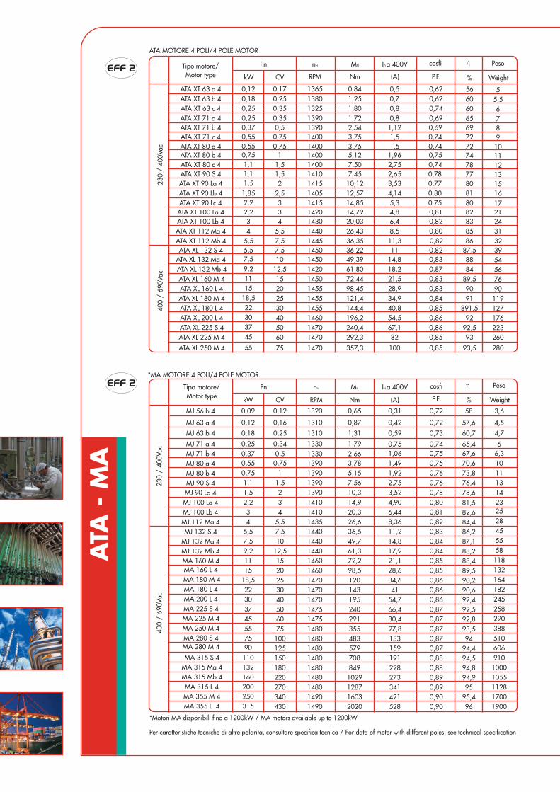
ATA
- M
A
*MA MOTORE 4 POLI/4 POLE MOTOR
ATA MOTORE 4 POLI/4 POLE MOTOR
*Motori MA disponibili fino a 1200kW / MA motors available up to 1200kW
Per caratteristiche tecniche di altre polarità, consultare specifica tecnica / For data of motor with different poles, see technical specification
ATA XT 63 b 40,12
0,25 1380 1,25 0,7 0,62 60 5,5ATA XT 63 c 4 0,35 1325 1,80 0,8 0,74ATA XT 71 a 4 0,35 1390 1,72 0,8 0,69 65 7ATA XT 71 b 4 0,5 1390 2,54 1,12 0,69 69 8
ATA XT 80 b 4 1400 5,12 0,75 11
ATA XT 90 S 4 1,5 1410 7,45 2,65 0,78 77 13ATA XT 90 La 4 2 1415 10,12 3,53 0,77 15
ATA XT 100 La 4 3 1420 14,79 4,8 0,81 82 21ATA XT 100 Lb 4 4 1430 20,03 6,4 0,82 83 24
230
/ 40
0Vac
ATA XT 112 Ma 4 5,5 1440 26,43 8,5 0,80
87,5
31
ATA XL 132 S 4 7,5 1450 36,22 11 39
400
/ 69
0Vac
ATA XT 63 a 4
ATA XL 132 Ma 4ATA XL 132 Mb 4ATA XL 160 M 4ATA XL 160 L 4ATA XL 180 M 4
ATA XL 200 L 4ATA XL 225 S 4ATA XL 225 M 4
ATA XL 250 M 4
Tipo motore/Motor type
Pn
kW CV
0,180,250,250,37
0,75
1,11,5
2,234
5,57,59,21115
18,522303745
55
1365
145014201450145514551455146014701470
1470
1
0,17
1012,515202530405060
75
nN MN
Nm
0,84
49,3961,8072,4498,45121,4144,4196,2240,4292,3
357,3
0,5
14,818,221,528,934,940,854,567,182
100
0,62
1,96 74
0,820,83
0,830,840,850,860,860,85
0,85
0,870,83
56
60
80
85
8884
89,59091
891,592
92,593
93,5
5
6
54567690119127176223260
280
In a 400V
(A) % Weight
Peso
ATA XL 180 L 4
RPM P.F.
cosfi
ATA XT 71 c 4 0,75 1400 3,75 1,5 0,74 72 90,55ATA XT 80 a 4 1400 3,75 0,74 100,55 0,75 1,5 72
ATA XT 80 c 4 1400 7,50 0,74 121,1 1,5 2,75 78
ATA XT 90 Lb 4 2,5 1405 12,57 4,14 0,80 161,85 81ATA XT 90 Lc 4 3 1415 14,85 5,3 0,75 172,2 80
ATA XT 112 Mb 4 7,5 1445 36,35 11,3 0,82 325,5 86
2,24
5,57,510
15202530
230
/ 40
0Vac
4050
400
/ 69
0Vac
Tipo motore/Motor type
Pn
kW CV
34
5,57,59,21115
18,522303745557590110132160200250315
12,5
3
6075
100125150180220270340430
nN
RPM
Mn
Nm
IN a 400V
(A)
cosfi
% Weight
Peso
MJ 71 a 4MJ 71 b 4MJ 80 a 4MJ 80 b 4MJ 90 S 4MJ 90 La 4MJ 100 La 4MJ 100 Lb 4
MA 160 L 4MA 180 M 4MA 180 L 4MA 200 L 4MA 225 S 4MA 225 M 4MA 250 M 4MA 280 S 4MA 280 M 4
MA 315 S 4MA 315 Ma 4MA 315 Mb 4MA 315 L 4MA 355 M 4MA 355 L 4
21,51
0,750,50,34
0,25
1,51,10,750,550,370,25
0,18MJ 63 b 4
MJ 112 Ma 4MJ 132 S 4
MJ 132 Ma 4MJ 132 Mb 4MA 160 M 4
P.F.
6,448,3611,214,8
21,128,634,641
54,766,4
4,90
80,497,8133159191228273341421528
17,9
3,522,751,921,491,060,75
0,59
5797088491029128716032020
26,636,549,761,372,298,5120143195240291
20,3
355483
14,910,37,565,153,782,661,79
1,31
25
455558118132164182245258
23
28
29038851060691010001055112817001900
141311106,36
4,7
82,6
86,287,1
88,4
90,290,6
92,5
88,2
81,5
84,4
89,5
92,4
92,893,594
94,494,594,894,995
95,496
78,676,473,870,667,665,4
60,7
0,810,820,830,840,840,850,850,860,860,86
0,80
0,870,87
0,870,880,880,890,890,900,90
0,870,87
0,780,760,760,750,750,74
0,73
14101435144014401440
1410
1490
14601470147014701475147514801480148014801480148014801490
1460
139013901390139013301330
1310
0,160,12MJ 63 a 4 0,420,87 4,557,60,721310
0,120,09MJ 56 b 4 0,310,65 3,6580,721320
η
η
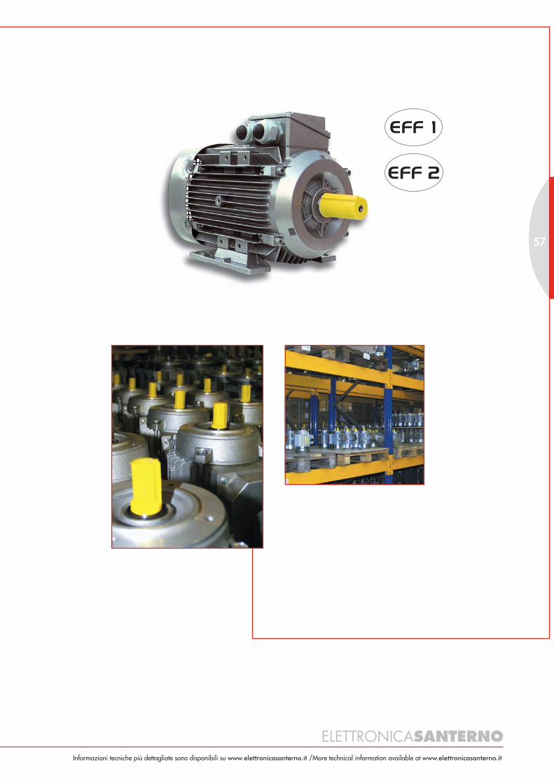
ELETTRONICASANTERNO
57
Informazioni tecniche più dettagliate sono disponibili su www.elettronicasanterno.it /More technical information available at www.elettronicasanterno.it
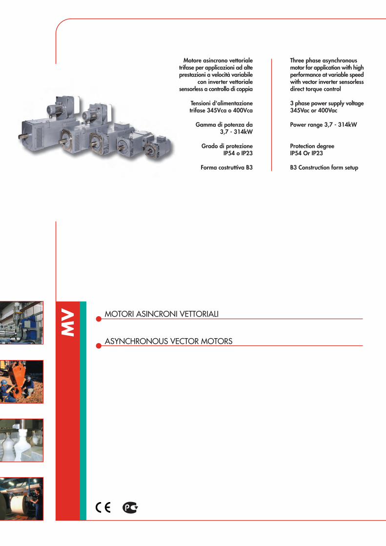
MV MOTORI ASINCRONI VETTORIALI
ASYNCHRONOUS VECTOR MOTORS
Three phase asynchronousmotor for application with highperformance at variable speedwith vector inverter sensorlessdirect torque control
3 phase power supply voltage345Vac or 400Vac
Power range 3,7 - 314kW
Protection degreeIP54 Or IP23
B3 Construction form setup
Motore asincrono vettorialetrifase per applicazioni ad alteprestazioni a velocità variabile
con inverter vettorialesensorless a controllo di coppia
Tensioni d'alimentazionetrifase 345Vca o 400Vca
Gamma di potenza da3,7 - 314kW
Grado di protezioneIP54 o IP23
Forma costruttiva B3

TECHNICAL FEATURES
Square made laminated statorCompact dimensions similar to dc motor of the same powerAuxiliary electro-fanThree phase four poles star windingSquirrel cage rotorLow losses laminated sheet constructionCompact square madeHigh maximum speed capabilityStator winding embedded bimetal type thermal probeHigh overload capabilityInsulation F classEpoxy gray color RAL 7031
OPTIONS
Special power supply voltagesEncoder or resolverAngus ring oil sealConstruction form B35 with extra precise flangeIP55 protection degree with stainless steel screwEmergency disk brakeTemperature probes PTC or/and PT100Internal heaterSpecial shafts and bearingsTropicalisationSpecial paintings
CARATTERISTICHE TECNICHE
Statore laminato quadratoDimensioni ridotte corrispondenti a motorizzazioni in CC
Ventilazione assistitaAvvolgimento statorico trifase a 4 poli
Rotore a gabbia di scoiattoloCostruzioni con lamiere a basse perdite
Forma quadrata, compattaElevata velocità massima di rotazione
Protezione termica con sonde bimetalliche inserite nell'avvolgimento statoricoElevata sovraccaricabilità
Classe di isolamento FFondo epossidico grigio RAL 7031
OPZIONI
Tensioni d’alimentazione specialiEncoder o resolver
Angus (anello para olio)Forma costruttiva B35 con flangia extraprecisa
Grado di protezione IP55 con viteria INOXFreni a disco di stazionamento o emergenza
Sonde di temperatura PTC o/e PT100Scaldiglia anticondensa
Esecuzioni speciali di alberi e cuscinettiTropicalizzazione
Verniciature speciali
ELETTRONICASANTERNO
59
T
Tn
nbasenmax1
n nmax2
P
Pn
nbasenmax1
n nmax2
Modello/Model
Potenza/Power(kW)
Velocità nominale/Nominal speed
(RPM)
Coppia/Torque
(Nm) [Tn]
Velocità max/Max Speed (RPM)
[nmax2]
Peso/Weight
(kg)
MV 100 3,7-17 21,6-63,7 8000 50-90
MV 133 16-431500-3000
92-191 7000 132-200
MV 160 28-64 1000-2600 195-334 5000-6000 255-350
MV 180 46-105 1000-2500 325-544 4500 480-550
MV 225 67-204 1000-2250 514-1289 3500 640-1100
IP54 TENSIONE ALIMENTAZIONE/POWER SUPPLY VOLTAGE 360Vac o 400Vac
Modello/Model
Potenza/Power(kW)
Velocità nominale/Nominal speed
(RPM)
Coppia/Torque
(Nm) [Tn]
Velocità max/Max Speed (RPM)
[nmax2]
Peso/Weight
(kg)
MV 133 21-52 121-229 7000 132-200
MV 160 38-88
1500-3000
266-458 5000-6000 270-365
MV 180 71-155
950-2550
466-859 4500 480-570
MV 225 104-314
1000-2500
798-1997 3500 640-11001000-2250
IP23 TENSIONE ALIMENTAZIONE/POWER SUPPLY VOLTAGE 360Vac o 400Vac
Informazioni tecniche più dettagliate sono disponibili su www.elettronicasanterno.it /More technical information available at www.elettronicasanterno.it
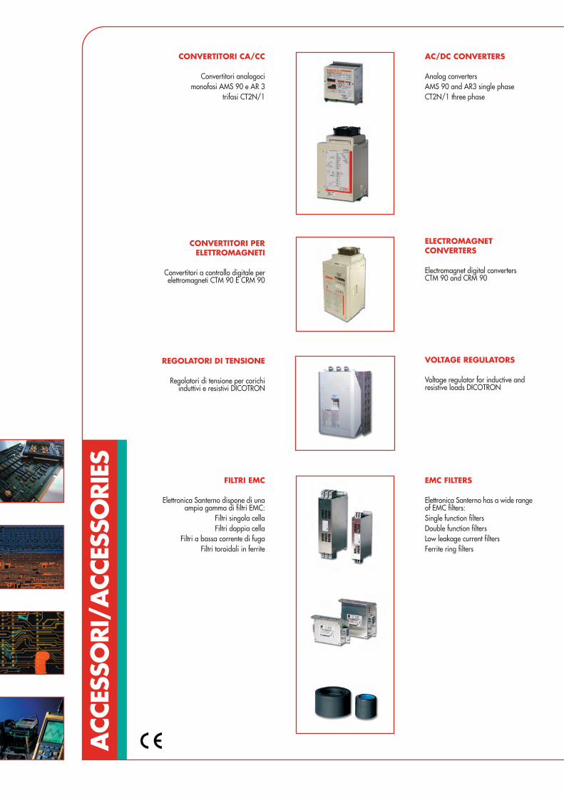
ACC
ESSO
RI/A
CCES
SORI
ES
EMC FILTERS
Elettronica Santerno has a wide rangeof EMC filters:Single function filtersDouble function filtersLow leakage current filtersFerrite ring filters
FILTRI EMC
Elettronica Santerno dispone di unaampia gamma di filtri EMC:
Filtri singola cellaFiltri doppia cella
Filtri a bassa corrente di fugaFiltri toroidali in ferrite
CONVERTITORI CA/CC
Convertitori analogocimonofasi AMS 90 e AR 3
trifasi CT2N/1
AC/DC CONVERTERS
Analog convertersAMS 90 and AR3 single phaseCT2N/1 three phase
CONVERTITORI PERELETTROMAGNETI
Convertitori a controllo digitale perelettromagneti CTM 90 E CRM 90
ELECTROMAGNETCONVERTERS
Electromagnet digital convertersCTM 90 and CRM 90
REGOLATORI DI TENSIONE
Regolatori di tensione per carichiinduttivi e resistivi DICOTRON
VOLTAGE REGULATORS
Voltage regulator for inductive andresistive loads DICOTRON
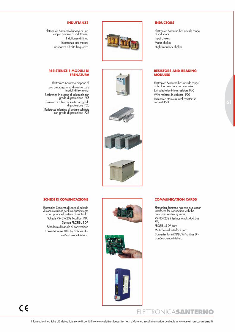
ELETTRONICASANTERNOInformazioni tecniche più dettagliate sono disponibili su www.elettronicasanterno.it /More technical information available at www.elettronicasanterno.it
61
RESISTENZE E MODULI DIFRENATURA
Elettronica Santerno dispone diuna ampia gamma di resistenze e
moduli di frenatura:Resistenze in estruso di alluminio con
grado di protezione IP55Resistenze a filo cabinate con grado
di protezione IP20Resistenze in lamina di acciaio cabinate
con grado di protezione IP23
RESISTORS AND BRAKINGMODULES
Elettronica Santerno has a wide rangeof braking resistors and modules:Extruded aluminium resistors IP55Wire resistors in cabinet IP20Laminated stainless steel resistors incabinet IP23
INDUTTANZE
Elettronica Santerno dispone di unaampia gamma di induttanze:
Induttanze di lineaInduttanze lato motore
Induttanze ad alta frequenza
INDUCTORS
Elettronica Santerno has a wide rangeof inductors:Input chokesMotor chokesHigh frequency chokes
SCHEDE DI COMUNICAZIONE
Elettronica Santerno dispone di schededi comunicazione per l’interfacciamento
con i principali sistemi di controllo:Schede RS485/232 Mod bus RTU
Scheda PROFIBUS DPScheda multicanale di conversione
Convertitore MODBUS/Profibus DP-CanBus-Device Net ecc.
COMMUNICATION CARDS
Elettronica Santerno has communicationinterfaces for connection with theprincipals control systems:RS485/232 interface cards Mod busRTUPROFIBUS DP cardMultichannel interface cardConverter for MODBUS/Profibus DP-CanBus-Device Net etc.
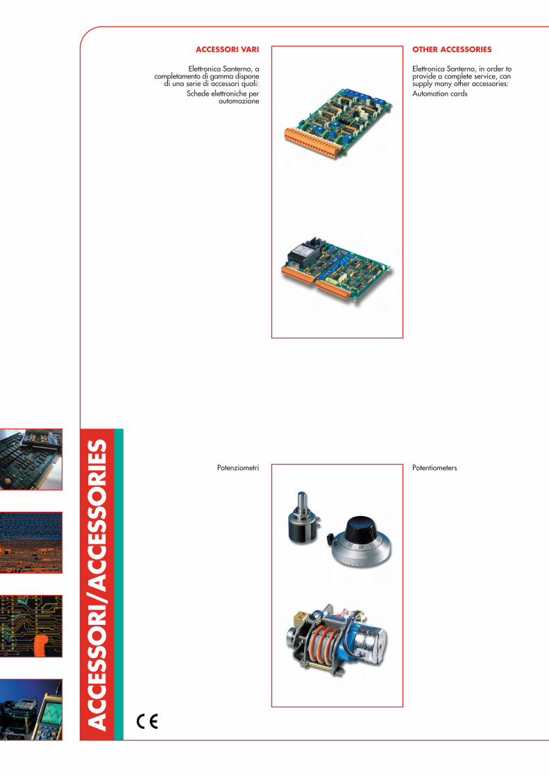
ACC
ESSO
RI/A
CCES
SORI
ES
ACCESSORI VARI
Elettronica Santerno, acompletamento di gamma dispone
di una serie di accessori quali:Schede elettroniche per
automazione
OTHER ACCESSORIES
Elettronica Santerno, in order toprovide a complete service, cansupply many other accessories:Automation cards
Potenziometri Potentiometers

ELETTRONICASANTERNO
63
Fusibili di protezioneBasi portafusibili
Protection fusesFuse-holders
Fusibili di protezioneBasi portafusibili
Protection fusesFuse-holders
Digital and analogue metersStrumenti fronte quadro digitali eanalogici
Accessori per protezione IP20 diconvertitori e impedenze
IP20 protection devices forconverters and inductors
Informazioni tecniche più dettagliate sono disponibili su www.elettronicasanterno.it /More technical information available at www.elettronicasanterno.it