3 nasa @ 19990116210 · @ 19990116210 spacecraft ... manufacturers are willing to produce...
TRANSCRIPT
NASA/TP--1999-209373 NASA/TP-1999-20937319990116210
@Spacecraft Environments Interactions:Space Radiation and Its Effects onElectronic SystemsJ.W. Howard, Jr.Computer Sciences Corporation, Huntsville, Alabama
D.M. HardageMarshall Space Flight Center, Marshall Space Flight Center, Alabama
LIBRARYCOPY ]
01/1"121999
LANGLEYRESEARCHCENTEr-::LIBRARYNASA
' HAMPTON,VIRGINIA
July 1999
https://ntrs.nasa.gov/search.jsp?R=19990116210 2018-06-11T12:55:40+00:00Z

The NASA STI Program Office...in Profile
Since its founding, NASA has been dedicated to • CONFERENCE PUBLICATION. Collectedthe advancement of aeronautics and space papers from scientific and technical conferences,science. The NASA Scientific and Technical symposia, seminars, or other meetings sponsoredInformation (STI) Program Office plays a key or cosponsored by NASA.part in helping NASA maintain this importantrole. • SPECIAL PUBLICATION. Scientific, technical,
or historical information from NASA programs,The NASA STI Program Office is operated by projects, and mission, often concerned withLangley Research Center, the lead center for subjects having substantial public interest.NASA's scientific and technical information. The
NASA STI Program Office provides access to the • TECHNICAL TRANSLATION.NASA STI Database, the largest collection of English-language translations of foreign scientificaeronautical and space science STI in the world. The and technical material pertinent to NASA'sProgram Office is also NASA's institutional mission.mechanism for disseminating the results of itsresearch and development activities. These results Specialized services that complement the STIare published by NASA in the NASA STI Report Program Office's diverse offerings include creatingSeries, which includes the following report types: custom thesauri, building customized databases,
organizing and publishing research results...even• TECHNICAL PUBLICATION. Reports of providing videos.
completed research or a major significant phaseof research that present the results of NASA For more information about the NASA STI Programprograms and include extensive data or Office, see the following:theoretical analysis. Includes compilations of
significant scientific and technical data and • Access the NASA STI Program Home Page atinformation deemed to be of continuing reference http://www.sti.nasa.govvalue. NASA's counterpart of peer-reviewedformal professional papers but has less stringent • E-mail your question via the Internet tolimitations on manuscript length and extent of [email protected] presentations.
• Fax your question to the NASA Access Help• TECHNICAL MEMORANDUM. Scientific and Desk at (301) 621-0134
technical findings that are preliminary or ofspecialized interest, e.g., quick release reports, • Telephone the NASA Access Help Desk at (301)working papers, and bibliographies that contain 621-0390minimal annotation. Does not contain extensiveanalysis. • Write to:
NASA Access Help Desk• CONTRACTOR REPORT. Scientific and NASA Center for AeroSpace Information
technical findings by NASA-sponsored 800 Elkridge Landing Roadcontractors and grantees. Linthicum Heights, MD 21090-2934

NASA Technical
' 3 1176014471313/,
NASA / TP--1999-209373
Spacecraft Environments Interactions:Space Radiation and Its Effects onElectronic SystemsJ.W. Howard, Jr.Computer Sciences Corporation, Huntsville, Alabama
D.M. HardageMarshall Space Flight Center, Marshall Space Flight Center,Alabama
National Aeronautics and
Space Administration
Marshall Space Flight Center • MSFC, Alabama 35812
July 1999

Available from:
NASA Center for AeroSpace Information National Technical Information Service800 Elkridge Landing Road 5285 Port Royal RoadLinthicum Heights, MD 21090-2934 Springfield, VA22161(301) 621-0390 (703) 487-4650
!ii
PREFACE
The effects of the natural space environment on spacecraft design,development, and operation are the topic of a series of NASA ReferencePublications* currently being developed by the Electromagnetics and AerospaceEnvironments Branch, Systems Analysis and Integration Laboratory, Marshall SpaceFlight Center. The objective of this series is to increase the understanding of naturalspace environments (neutral thermosphere, thermal, plasma, meteoroid and orbitaldebris, solar, ionizing radiation, geomagnetic and gravitational fields) and theireffects on spacecraft, thereby enabling program management to more effectivelyminimize program risks and costs, optimize design quality, and achieve missionobjectives.
This primer, eighth in the series, outlines the radiation environmentsencountered in space, discusses regions and types of radiation, applies theinformation to effects these environments have on electronic systems, andaddresses design guidelines and system reliability.
See NASA RP 1350 for an overview of eight natural space environments(including space radiation) and their effects on spacecraft.
* NASA Reference Publications Natural Space Environments Series, available fromthe Marshall Space Flight Center Electromagnetics and Aerospace EnvironmentsBranch, include the following:
"The Natural Space Environment: Effects on Spacecraft," James, B.F., Norton, O.A.,Jr., and Alexander, M.B., November 1994, NASA RP 1350.
"Spacecraft Environments Interactions: Protecting Against the Effects of SpacecraftCharging," Herr, J.L. and McCollum, M.B., November 1994, NASA RP 1354.
"Electronic Systems Failures and Anomalies Attributed to ElectromagneticInterference," Leach, R.D. and Alexander, M.B., July 1995, NASA RP 1374.
"Failures and Anomalies Attributed to Spacecraft Charging," Leach, R.D. andAlexander, M.B., August 1995, NASA RP 1375.
"Spacecraft Systems Failures and Anomalies Attributed to the Natural SpaceEnvironment," Bedingfield, K.L., Leach, R.D., and Alexander, M.B., August 1996,NASA RP 1390.
"Spacecraft Environments Interactions: Solar Activity and Effects on Spacecraft,"Vaughan, W.W., Niehuss, K.O., and Alexander, M.B., November 1996, NASA RP1396.
iii

"Meteoroids and Orbital Debris: Effects on Spacecraft," Belk, C.A., et al, August 1997,NASA RP 1408.
iv

TABLE OF CONTENTS
Pa_o
INTRODUCTION........................................................................................................................... 1
SPACERADIATION ENVIRONMENT....................................................................................... 2
Sources ...................................................................................................................................... 2Near-Earth Radiation Environment ........................................................................................... 5
Trapped Environment .......................................................................................................... 5Transient Environments ...................................................................................................... 7Summary ............................................................................................................................. 7
EFFECTS OF RADIATION ........................................................................................................... 8
Radiation Interactions ............................................................................................................... 8Effects of Radiation on Electronics........................................................................................... 9
Total Ionizing Dose ............................................................................................................. 9Displacement Effects......................................................................................................... 11Single Event Effects .......................................................................................................... 12
DESIGN GUIDELINES AND RADIATION ENVIRONMENT PREDICTIONS ..................... 15
CONCLUSIONS ........................................................................................................................... 19
GLOSSARY.................................................................................................................................. 20
REFERENCES .............................................................................................................................. 23
V

LIST OF ILLUSTRATIONS
Figure Title Page
1. Cartoon depicting all the radiation types that a spacecraft can experience ..............2
2. Two-dimensional artist's depiction of the trapped radiation environment .........3
3. Three-dimensional views of the trapped radiation environment ..........................4
4. Pictogram showing regions of space where radiation types are significant ............5
5. Contour plot of the trapped proton environment overlaying a map of
the Earth ................................................................................................................................. 6
6. Plot of trapped electron flux as a function of relative orbital time for a 900-kinpolar orbit .............................................................................................................................. 6
7. Plot of daily dose rate and total ionizing dose (TID) as a function of days
in orbit .................................................................................................................................... 7
8. Diagram of radiation environment effects on electronic systems ............................8
9. Plot of mission dose as a function of 4_ aluminum spherical shield
thickness .............................................................................................................................. 15
10. Single event effects (SEE) producing environment for a polar orbit .....................17
vi

LIST OF TABLES
Table Title Page
1. Example of electrical test data from a TID qualification test .....................................11
2. Listing of single event effects acronyms .......................................................................13
3. Example of solar cell displacement effects predictions ..............................................16
vii

ACRONYMS AND ABBREVIATIONS
AT&T American Telephone & TelegraphCCD Charge Coupled Devicecm centimeter
CMOS Complementary Metal Oxide SemiconductorEDAC Error Detection And Correctione V electron voltGCR Galactic Cosmic RadiationISC short circuit currentkeV kiloelectron voltkm kilometerkrad kilorad
LET Linear Energy Transfermg milligrammil distance equal to 1/1000 of an inch.MeV Megaelectron voltMSFC Marshall Space Flight CenterNASA National Aeronautics and Space AdministrationPMAX maximum powerrad-hard radiation hardened
SAA South Atlantic AnomalySEB Single Event BurnoutSEE Single Event EffectsSEGR Single Event Gate RuptureSEIDC Single Event Induced Dark CurrentSEL Single Event LatchupSEMBE Single Event Multiple Bit ErrorSEFI Single Event Functional InterruptSET Single Event TransientSEU Single Event UpsetTDE Total Dose ExposureTID Total Ionizing DoseVOC open circuit voltage
viii

SPACECRAFT ENVIRONMENTS INTERACTIONS:SPACE RADIATION AND ITS EFFECTSON ELECTRONIC SYSTEMS
INTRODUCTION
In the last 25 years the National Geophysical Data Center recorded over 4500spacecraft anomalies or malfunctions that have been traced to the effects of the spaceradiation environment.' These occurrences range from solar array to attitudecontrol problems. While glitches in the power supplies or upsets in the datadownlink may be considered minor effects, a loss of attitude control is a catastrophic,possibly mission-ending, effect.
With the advent of the "smaller, better, cheaper, faster" philosophy, spacecraftsystems increasingly use modern microelectronics manufactured by commercialprocesses. Modern microelectronics continually decrease feature size and increasecomponent density. These practices and other requirements for advancedtechnologies, increase radiation sensitivity. Utilization of commercial technologyadds more risk through the use of electronics that are not "hardened" to theradiation environment.
Major complaints about working with radiation-hardened electronics are costand availability. The cost to harden a satellite to the natural space radiationenvironment by using rad-hard electronics is typically about one percent of the totalsystem cost. 1With possible mission-ending effects, this seems a trivial argument. Inaddition, the cost comparisons made do not always include all hidden costs. Whenusing commercial technology, pre-existing radiation test data cannot be used.Enough lot-to-lot variation occurs in these parts to consider them different parts.Therefore, every lot of commercial parts procured for a mission with radiationrequirements must have radiation testing. This process is time consuming andexpensive. For a fair comparison, these costs must be included in any cost analysis.
The availability argument, however, is becoming closer to reality. While theoriginal argument was that all types of parts were not available, now fewermanufacturers are willing to produce radiation-hardened electronics. In the lastfive years Texas Instruments, Intel, TRW, LSI Logic, and AT&T exited theradiation-hardened microelectronics market. _ What this means for the spacecraftsystem designers is that designing for the radiation environment will becomeincreasingly difficult if this exodus continues. It also means a heightened awarenessto the radiation environment and its effects on electronic systems is needed. Hence,this primer provides a broad overview of the natural space radiation environmentand its effects on spacecraft systems.

SPACE RADIATION ENVIRONMENT
Sources
The same typesof radiation exist throughout the entire region of space in ourknown solar system. Thequantities and spectrumof these radiation types vary withlocation in the solar system. This primer deals only with the near-Earth radiationenvironment (i.e., the environment experiencedbyEarth orbitingspacecraft).Thissection introduces the source of radiation in the near-Earth regions and thefollowingsection discusses these in detail.
The near-Earth radiation environment can be divided into a trapped radiationenvironment and transient radiation environments. A depiction of theseenvironments is shown in Figure 1. The trappedenvironment is due to the Earth'smagnetic field confining chargedparticles to certain regions of space.These regionsare termed the "Van Allen Belts." Nominally there will be one proton and twoelectronbelts (innerand outer),though this can temporarilychange with largesolarevents. The transient environments are due to the effects of the Sun (solar windand flares) and galactic cosmic radiation (GCR). A two-dimensional artist'sdepiction is shown in Figure2 and a three-dimensional model-based view of thesetrapped belts is shown in Figure3.2
Cosmic f Spacecra__ Rays Trajecto_
Earth's
Radiation e
Belts
Figure 1. Cartoon depicting all the radiation types that a spacecraft can experience, including the innerand outer trapped radiation belts, solar flares, and galactic cosmic radiation
2

The transient radiation environments, consisting of solar wind, solar flares,and galactic cosmic radiation, exist in the interplanetary space regions as well as thenear-Earth regions. The solar wind consists of low energy electrons and protons andis typically only energetically significant for externally mounted spacecraftcomponents. This wind is generally ignored because it is insignificant comparedwith other radiation sources.
Figure 2. Two-dimensional artist's depiction of the trapped radiation environment 3
The other solar-induced radiation environment is solar "flares" (The generalterm flare is used for convenience to represent all types of solar radiation events).When a magnetic disruption in the solar photosphere occurs, a variety of radiationtypes and energies erupt from the Sun into space. This flare can produce energeticprotons and heavy ions that will produce effects in electronics (described in the nextsection). An important influence on solar particle radiation (and all transientenvironments) is the Earth's magnetic field. The magnetic forces that cause chargedparticles to be trapped, also act on charged particles in flares. For a given magneticfield strength, an incident particle energy is required to penetrate that magnetic field.All lower energy particles are deflected along the magnetic field lines. This magneticscreening can be significant for satellites in low-Earth orbit.
The third source of radiation is galactic cosmic radiation. GCR is electrons,protons, and heavy ions (charged particles with atomic number greater than one)that are believed to have an origin outside the solar system and to beomnidirectional. As with the solar flare environment, this radiation source issignificant in the near-Earth environment. The GCR is affected in the same manneras solar particles due to the effects of the Earth's magnetic field (i.e., low altitudeequatorial orbits will receive significant screening, while higher inclination oraltitude receive less).

Figure 3. Three-dimensional views of the trapped radiation environment. Top view shows the truetoroidal shape of the radiation belts, with transparent green representing the outer electron belt andsolid green the proton belts (data from a particularly strong storm event where a second proton belt wasformed). Bottom, edge-on view shows cross-sectional data for the belt regions with low to high densityrepresented by blue to red.
4

Near-Earth Radiation Environment
Trapped Environment
Figure 4 shows the approximate regions of space the various radiationenvironments occupy. Since boundaries of the bands are not sharp transitions, theindicated numbers should be considered approximations. The trapped radiationbelts extend from approximately 500 km to about 12 Earth radii (roughly 76,000 kin).Normally, over this range there are two electron bands (with different populationand energy spectra) and one proton band. As shown in Figure 3, however,sometimes a departure from normalcy occurs. Figure 3 is based on data from asevere solar event, lasting for many weeks, in 1989 that formed a third electron belt(between the inner and outer zones) and a second proton belt (higher in altitude).
-3.8 _)oc -12'.0
-2:8 ~5"0 .oi I t-
O 0
REGION ' ' _.(/)o
InnerZone Electrons
Outer Zone Electrons
Trapped Protons
I
Solar Flare Protons/GCR
2 3 4 5 6 7 8 9 10 11 12 13 14 15EquatorialRadius (Earth Radii)
Figure 4. Pictogram showing regions of space where radiation types are significant. 4 Regions areplotted as a function of the equatorial radius, in Earth radii (-6370 km), because the belts vary withthe magnetic field that changes with increasing inclination off the equator.
A specific region of space that warrants special coverage is the South AtlanticAnomaly (SAA). The Earth's magnetic field axis does not point to geographic northand does not pass directly through the center of the Earth. The combination causes adeformation of the magnetic field over the South Atlantic (magnetic field lines diplower in altitude) and over Southeast Asia (field lines are higher in altitude). Thenet effect is the harshness of the radiation belts is seen at lower altitudes in the SAA
region (Figure 5). Thus, for spacecraft in low-Earth orbit, this region tends todominate the observed radiation environment. For systems at higher altitudes,however, this effect is less significant.
5

Figure 5. Contour plot of the trapped proton environment overlaying a map of the Earth? Protondensity increases from blue to green to yellow to red. Contours highlight the South Atlantic Anomaly(SAA) where the radiation particle population is high due to the offset nature of the Earth's magneticfield.
Another important point is the orbit of a spacecraft can take it into and out ofthe radiation belts. Figure 6 shows the electron environment as a function of timefor a satellite in low-Earth polar orbit. It is evident there are times of radiationexposure followed by times of no exposure.
107
North EquatorialPolar Region South Electron Flux I North
Polar FluxFree I PolarRegion Region r-I Region10aNorthern Southern
Horn Horn Southern Northern
_ 105 Horn1 Horn×
= 10 4
m Equatorial Region103 Globally Opposite
o tile SAA-="_.G
r, 10 2
101 1,_, I,,,IJl,,,i)ll,l,,i,l,,_,l,ltll:,,,lll jll,,,,i,,i,i, ii I
0 20 40 60 80 100 120
Relative Time (Minutes)
Figure 6. Plot of trapped electron flux as a function of relative orbital time for a 9(X)--kmpolar orbit. 4The graph shows the regions of the radiation belts and the noncontinuous exposure. Note: hornidentifies regions of space (at high latitudes) where the outer electron belt is seen at lower altitudes.

Net effect of this orbital variation of the radiation environment is the build-up
of total ionizing dose (TID) occurs at different rates (giving a fine structure to a doseversus time curve, shown in Figure 7) and the single event effects (SEE)susceptibility is only for a certain portion of the orbit (both of these are discussed indetail in the Effects of Radiation section). Understanding this orbital variation isimportant to properly predict the environment, design ground-based tests, andaccurately predict the rate effects.
c5
_ 1000
100_5
0 100 200 300 400
Days in Orbit
Figure 7. Plot of daily dose rate and total ionizing dose (TID) as a function of days in orbit. Visible arethe effects of flux free time in the dose rate curve. For long term averages the TID curve shows anaverage dose rate value (not a bad assumption) but jumps exist when the dose is viewed locally in time.
Transient Environments
The previous section discussed the sources and nature of the transientenvironments. The issue here is their impact in the near-Earth regions. In Figure 4,the bar representing the solar flare protons depicts the upper end of theenvironment extending throughout space, whereas, the lower end shows the pointwhere geomagnetic effects are beginning to remove some of the environment. Sincethis removal is a strong function of particle energy, altitude, and inclination,depicting how the gray bar extends down in altitude is problematic. Detailedcomputer calculations are required to predict this geomagnetic cutoff effect. Becausethis same region of space and geomagnetic effects are associated with galactic cosmicradiation, this bar is used to represent GCR as well.
Summary
This section briefly outlined the radiation environments encountered in space.The discussion included regions and types of radiation, as well as specialconsiderations such as orbital variations and the South Atlantic Anomaly. Thefollowing section applies some of this information to the effects these radiationenvironments have on electronic systems.

EFFECTSOF RADIATIONRadiation Interactions
To understand the effect radiation in space has on electronics systems, onemust first understand the radiation environment and how it interacts in electronic
materials. The natural space radiation environment was addressed first in thisprimer. To do an overview of the effects of radiation on electronic systems, the onlyinformation needed from that section is the environment consists of electrons,
protons, and heavy ions. Making predictions, discussed in the next section, requiresusing detailed knowledge of particle types, energy spectra, and density.
Figure 8 shows a diagram of the radiation environment and its effects onelectronic systems. The flow is from the radiation environment (top) to interactionsthat take place (middle) to effects that these interactions lead to (bottom). Observefirst the inclusion of photons in the electron box. While high energy photons do notrepresent a significant portion of a natural space environment, the interaction of theelectrons in surrounding spacecraft materials can produce a locally significantphoton population. Since the photon interactions in electronic materials produceonly high energy electrons which are indistinguishable from the naturalenvironment electrons, their interactions and effects are included in the naturalelectron environment.
\
N\
\
total Ionlzin_ q \,_ Disp_ace_L_'nt _ SingleEvent -,_
Figure 8. Diagram of radiation environment effects on electronic systems
8

The middle section of Figure 8 shows two interactions. While four boxes areshown, electronic and nuclear are the only interactions. In electronic interactions,the incident radiation interacts with the surrounding charge of the atom (i.e., theelectrons ). The effect of this type interaction is to transfer energy from the radiationto the atom. The newly acquired energy raises the energy state of the atom to ahigher level and causes an excitation or ionization of electrons within the atom. Forelectronic materials, an increased number of electrons (and associated positive ion)become available for conduction or other effects within the crystalline structure ofthe semiconductor. If sufficient energy is transferred, the atom can become sothermally stimulated it leaves its lattice site. In general, this is a small percentageinteraction that requires a significant electron flux to produce noticeable effects(hence, a dashed line to the displacement damage box). Heavy ion electronicinteractions, however, deposit a significant amount of energy. Therefore, along withthe link to the single event effects which depend on the transient charge generated,a direct link is made between the heavy ion electronic interactions and thedisplacement damage box.
For the nuclear interaction to take place, radiation must interact directly withthe nucleus of the atom. Here the incident radiation must overcome the electronicreaction with both the electrons and the nucleus so that it approaches the nucleussufficiently close so direct nuclear interaction is possible. While all radiation typesshow paths through an electronic interaction box, only the protons have a paththrough the nuclear interaction box. Only protons, with their unitary charge andhigh energies, interact with any reasonable probability with the nucleus. Once thenuclear interaction begins there are many ways the atom can display the effects. Somuch energy is transferred in this type interaction, it is easy to have the atomphysically displaced from its original location or even, in effect, explode,fragmenting the nucleus into smaller pieces. Nuclear interactions have a moredramatic impact but the probability of occurrence is much lower than the electronictype of interaction.
The bottom layer of Figure 8 shows three effect categories: total ionizing dose,displacement damage, and single event effects. A discussion follows of each categorywith an outline of the basic effects. Examples of how the spacecraft environmentproduces these effects and possible mitigation techniques are given.
Effects of Radiation on Electronics
Total Ionizing Dose (TID)
The term, total ionizing dose, implies the dose is deposited to the electronicsthrough ionization effects only. From the above discussion, energy deposited byradiation moves the electrons to a higher energy state, thus making them availablefor conduction and mobile inside a nonconductive material. These electrons, or
more correctly the positive charge created by ionization, are the prime cause of thetotal ionizing dose effects.
In general, all types of electronics are susceptible to ionization but the chargegenerated inside the semiconductor material can quickly be collected and removed
9

without ill effect (assuming the radiation interaction rate is at the low level of thespace environment). If a semiconductor device contains, for example, a silicondioxide/silicon interface (as in all modern integrated circuits based oncomplementary metal oxide semiconductor (CMOS) technology), charge generatedinside the oxide can become trapped at the interface. This trapped charge, bychanging the potential of the interface structure, can lead to increased "leakage"current or changed operational characteristics of any device using this structure (ifthis interface exists at a biasing point).
From an engineering perspective, these macroscopic effects are important indetermining the reliability of electronics to the ionizing dose environment. Todetermine a part's reliability in this radiation environment, a detailed set of test datais required. Simply testing a part for functionality after exposure to a given radiationlevel may not be sufficient. Parametric data must be taken with functionality testingover smaller dose steps than one-shot, go/no-go testing. Test data for all parts in agiven design must be reviewed for meeting all specifications (not just functionality).Table 1 shows typical data from a TID test: the part's parameters, data sheetspecifications, and the effects on those parameters as a function of the total doseexposure (TDE), and annealing steps. The word anneal, here, is a misnomer. Noimprovement is implied; it is simply a temperature over time treatment withoutthe influence of the radiation environment. This data shows the parameters Icc_ttl,Icch_cmos, and PSSR_A no longer meet manufacturer's specification at completionof the testing. This information must be combined next with aging and temperatureeffects. Finally, overall degradation must be compared with actual circuitspecification to ensure proper operation throughout mission lifetime.
Test data must also show information useful for mission procured electronics.A high degree of variability in test results is possible for the same parts from thesame lot from the same manufacturer. The data presented in Table 1 are for one partand only shows 10 electrical parameters and their results. Actually this part had 53parameters tested for each of the cited conditions. Actual testing should include anumber of parts from the same lot and the data should be treated statistically basedon observed variability and sample size. Variability results from the attention paidby the manufacturer to designing and building parts while being mindful of theradiation environment. A manufacturer producing a "rad-hard" part will have asmall amount of variability. A mass produced part for the commercial market,however, can have extreme variations. Therefore, testing should be tailored for theradiation quality of the commercial part (i.e., from accepting previous test data forrad-hard parts to performing piece-part testing). As more and more manufacturersleave the radiation tolerant market, testing of parts becomes more critical to systemdesign.
10

Table 1. Example of electrical test data from a TID qualification test
In general, TID effects are mitigated through proper use of shielding materials.These effects depend on transfer of energy from the radiation environment. If theparticle environment population or its energy is decreased, the effect is lessened, i.e.,exactly what shielding does. By forcing the particle to transport through anintervening material, the environment interacts and loses energy (sufficient energyloss can mean the particle never enters the electronics). By appropriately selectingthe shielding material and its thickness, mitigation is optimized. Since nothing isfree, the cost associated with shielding is weight. Putting weight into orbit costsmoney. Therefore, the tradeoff is survivability or reliability of electronic systemsversus added cost to get systems into space. Also, the effect of shielding is not linear.At some point, depending on the environment and relative "hardness" of theelectronics, addition of reasonable shielding is no longer effective. The only reliablemitigation is replacement of the part with a more tolerant version. This point willbe demonstrated in the final section.
Displacement Effects
The second area of the cumulative effects of radiation is displacement effects.When radiation interacts with the material, either electronically or via directnuclear interaction, energy is imparted to the atom as a whole. This energy istypically seen as heat by the increasing vibrational motion of the atoms. Or ifsufficiently high, the energy supplied to the atom can overcome the binding energyof the atom in the crystalline lattice of the material. If this occurs, the atom is"'displaced" from its normal position to various end locations. Unless the endlocation is an exact duplicate of the former position, the regular order of thecrystalline lattice is disturbed.
This regular order gives semiconductor materials their unique properties. Thedisturbance causes changes in the operation of any device exposed to thisenvironment (level of dose a device is susceptible to varies, but all electronics are
11

affected). This change may add a current path that previously did not exist (allowingincreased leakage current) or make conduction more difficult in regions designedfor flow. For example, diodes become less effective (two-way current flow becomeseasier) and the inherent amplification capabilities of transistors diminish. Similar tothe total ionizing dose, effects of displacement damage are cumulative. With smallexposure to a radiation environment observable effects are small but effects buildwith exposure time.
The solar cell is an example for this category since it displays these describedeffects and is a common element to most spacecraft. The solar cell is basically a diodewith one side exposed to the illumination of the Sun. Simply put, photons hit thedevice, creating electrons. The electric field of the diode (cell) allows the electrons tobe collected, thus, generating power. To repeat, with exposure to radiation, diodesbecome less effective. Diode leakage current increases, generated electrons "live" formuch shorter time periods, and the internal electric field decreases. All these effectscombine to make the solar cell less efficient producing power. Power reductions of50 percent are possible depending on solar cell construction and the environment towhich the cell is exposed. In general, shielding is effective for mitigatingdisplacement effects, but adding shielding to resolve this solar array problem isdifficult. The shielding (called cover glass in this application) must be transparent tothe optical photons and make a good optical interface at the solar cell (minimizerefractive effects). Even with these conditions met, transmission losses increase withincreasing cover glass thickness. Therefore, a balance must be reached betweenallowable radiation degradation and cell power production efficiency.
Single Event Effects (SEE)
Single event effects (SEE) are effects in microelectronics induced by the passageof a single particle through the part. This is the area where high energy protons(both from trapped environment and solar flares) and galactic cosmic radiation areimportant. It is interesting to note the first prediction of GCR effects onmicroelectronics came in 1962 in a paper by Wallmark and Marcus? They stated theultimate scalability (how small devices can be made) of electronics would be limitedby the direct ionization effects of GCR. While not correct in the scalability limit, theydid correctly predict single event effects over 10 years prior to any observation of theeffect.
SEE is a generic term encompassing all possible effects. Over the 20 years thateffects of single particles have been investigated, many acronyms were devised toindicate the effects caused by these single particles. The most common of these aresingle event upset (SEU) and single event latchup (SEL). Acronym practice attachesto SEa letter or letters that indicate the effect. With the wide range of effects andassociated acronyms, it is accepted in the radiation effects community to refer to SEE,then draw the distinction between destructive and nondestructive events. Examplesof events defined (and observed) to date are shown in Table 2.
12

Table 2. Listing of Single Event Effects Acronyms
Upset Digital circuit changes logic state
Latchup Device switches to a destructive, high currentstate
Gate Rupture Destructive failure of a power transistorBurnout Another mode of destructive failure for a
power transistor
Functional Interrupt Device enters mode where it is no longerperforming the designed function
Multiple Bit Error More than one logic state change from one ionTransient Transient current in circuit
Induce Dark Current Increased dark current in CCD arrays
From a systems engineer's point of view, exactly how upsets occur is lessimportant than how to accurately predict the rate these events occur. Since all singleevent physics is not completely understood, the only recourse to achieve a rateprediction is to perform experiments on a part-by-part basis. Experiments at aspecial facility count and correlate every ion and event in the electronics. The resultis cross section versus energy data for protons and cross section versus linear energytransfer (LET) for heavy ions. LET is a parameter that indicates how a particle losesenergy as it passes through a material. Cross section is an indication of thesusceptibility of a part to the event (a large number implies more susceptible, a smallnumber, less). Cross section is used because the units are area units (cm2). Theabscissa of these experiments (energy for protons and LET for heavy ions) is based onan important parameter for the event to occur. Since protons have a direct nuclearinteraction, no directional/depth dependence exists so the particle's energy is used.For heavy ions that can dramatically change energy and LET over the sensitiveregion of a part, a strong directional/depth dependency does exist. Therefore, aparameter must be used that can deal with this dependency. LET is such aparameter.
To get to a rate prediction for the mission, the part-by-part experimentalinformation must be appropriately merged with the environmental data predicted.Not only must this be done on a part-by-part basis but also on an effect-by-effectbasis. If a part is susceptible to both upset and latchup, experiments must measurethe cross section of both effects and predict a rate for each. Typical units used for rateprediction are events per bit-day or events per device-day. The word events isreplaced with upsets, latchups, etc., as appropriate. Use of per bit or per device isarbitrary. To convert from per bit to per device, multiply by the number of bitssusceptible to that type single event effect in the device.
Unlike TID and displacement effects, single event effects gain little help fromshielding. Unless a part is extremely susceptible to low energy or low LET single
13

event effects (indicates a very high rate of events), adding shielding does notsignificantly degrade the environment producing the effects. A general rule ofthumb is SEE cannot be shielded against. The main option to reduce these effects isparts selection. If parts selection is not an option (e.g., no other available part withthe functionality), circuit level mitigation techniques are used. Examples are errordetection and correction (EDAC) circuitry and voting. A simple EDAC example isusing a checksum bit. Each row in a memory array has an additional bit that stores a1 or 0 if the sum of the other bits is odd or even, respectively. If a bit in that row isupset, the new checksum does not agree with the stored checksum bit, hence, anerror.
On a mission critical system or a system where EDAC may not be effective,multiple numbers of parts of concern are operated concurrently. The voting methodtakes advantage of the low rate at which SEE occur, i.e., the extremely rareprobability of more than one part upsetting in exactly the same way and producingthe same type output error within a short period of time. If an odd number ofconcurrent parts is employed, a vote is taken of the output of the parts and majorityrule is observed. This method is very effective detecting errors but must be weighedagainst the increased cost and complexity required.
This section discussed three categories of radiation effects, gave examples, andbriefly outlined mitigation options. Using knowledge of these effects and theradiation environments an electronic system can be exposed to in space, acomprehensive set of design guidelines should be implemented. These guidelinesneed not indicate only the environment, but also the environmental effects. Theuncertainty in these should be shown through the proper use of engineering designmargins. Only through strict adherence to design guidelines and margins can systemreliability be properly considered. The next section addresses the design guidelinesand reliability issues.
14

DESIGN GUIDELINES AND RADIATION
ENVIRONMENT PREDICTIONS
To enhance electronic system reliability in the space radiation environment,specific design guidelines that address the effects described in the previous sectionshould be implemented. An integral part of design guidelines is the environmentpredictions for the electronics design engineer. Typically, a project report thatincludes the explicit particle environment and a processed version of thisinformation is generated for the design engineer. An example is shown in Figure 9.
1117
2000 km 103° Orbit for 378 Daysl
11)"
! Electrons/Brems
hE Trapped Protons---- Solar Proton
"_ 10_ TOTAL4
1114
10_
1112 : , I ' I ' I ' I ' I ' I ' I0 211 40 60 8(1 I(X) 120 140
Shield Thickness (mils)
Figure 9, Plot of mission dose as a function of 4n aluminum spherical shield thickness. Dose axis may beeither a mission dose (this case) or an annual dose for long duration missions,
To a first order approximation the electronics container (system box andspacecraft) is considered a spherical aluminum ball with the electronic part at thecenter. To use Figure 9, assume an average thickness (box wall thickness plus thespacecraft skin thickness) for a given system and estimate the mission dose thesystem parts receive. For example, assuming a 120-mil average thickness, theexpected mission dose is approximately 12 krads. If all electronics in this box can beshown to maintain reliability at this level of radiation with some design margin(typically a factor of 2 to 10, assuming a margin of two, gives 24 krads in thisexample), then the system analysis is complete. If not, more detailed dose analysis isneeded, additional radiation shielding required, or the affected parts replaced withmore radiation tolerant versions.
The decision to go to a more tolerant part is often based on the effectiveness ofadditional shielding. From Figure 9, approximately 60 mils of additional shieldingdecreases the dose at the 80-mil point by a factor of two (approximately 20 to 10
15

krads). On the other hand, about 8 mils of additional shielding reduces the dose atthe 20-mil point by the same factor of two (approximately 320 to 160 krads). Athigher initial shield thickness, this difference becomes even more apparent as thedose-depth curve (Figure 9) continues to flatten. Therefore, it becomes less costeffective (in weight) to add shielding to reduce dose to electronics if much shieldingis already present.
The second area to consider in environment prediction is displacement effects.It was once assumed that on a typical mission the only items particularly sensitiveto the displacement environment are solar cells. Recent studies show that otherdevices such as precision voltage references and optocouplers have enhanceddegradation from displacement effects. Therefore, if the expected missionenvironment includes a significant displacement damage environment, thensuspect parts must be tested and evaluated for these effects. Which parts are suspectsand how vulnerable they are is an active area of research.
Solar cells, however, have been studied extensively for these effects.Continuing with solar cells as the example, the normal environment predictiondocument includes this effect in a table indicating the effective 1 MeV electron fluxfor a variety of solar cell materials and cover glass thickness (Table 3).
Table 3. Example of solar cell displacement effects predictions. All values are in units of 1 MeVequivalent electron flux per year.
6 4.20E14 4.20E14 1.60E14 1.54E14 2.16E14 7.71E138 2.64E14 2.64E14 9.88E13 1.06E14 1.49E14 5.34E1312 6.40E13 6.40E13 2.64E13 1.99E13 2.78E13 9.82E12
The values presented in Table 3 are used by the solar cell design team toevaluate how various solar cells perform in flight in the specified radiationenvironment. These generic values are based strictly on the environment for theorbit of interest and typical solar cell materials. By coupling these values withradiation test data (typically supplied by the manufacturer), the solar cell designteam can predict the electrical performance of solar cells at mission end.
The final example of radiation environment prediction, often the mostdifficult, is the single event effects. Figure 10 shows the environment prediction forSEE environment during solar minimum conditions. During an active solar periodwhen solar flares can occur, a second curve is typically added to indicate possibleconditions in that extreme environment. As pointed out in the previous section, toaccurately predict the rate at which the single event effects occur, electronics testingis required. This test data must be combined with the environment data (presentedin Figure 10) to determine the actual rate at which these effects occur. Since theeffects prediction rate inherently relies on the test data for the specific electronic part,this type prediction is not possible until parts are identified. Thus, designs must bean interative process. Preliminary designs are completed first, then evaluated for
16

SEE. This evaluation returns to the designer with recommendations for partreplacement and/or circuit modifications. This iterative process continues untilboth designer and radiation engineer are satisfied with the design. If not done in thismanner, a dilemma can arise when a part is identified as a problem but the design istoo far along to change the part or system design.
10 2
I01 ............................................. ;........._............ _---_...;......................................i...................:........................._......
_, 10"1
102 ............
lO-_............ 1 bit ..............................................................
10-5
10"6
1 10 100
Linear Energy Transfer (MeV cm2/mg)
Figure 10. Single event effects (SEE) producing environment for a polar orbit. An important feature isthe rapid reduction in the environment for LET greater than approximately 28.
There are methods to alleviate SEE problems. The first divides all the spacecraftsystems into three categories such as vital, mission important, and non-critical.Once systems are categorized, intelligent parts procurement of appropriate level ofradiation hardness is possible.
Vital systems include areas of life support, attitude control, etc. These systemscannot tolerate any effects (i.e., one upset may jeopardize mission safety or causecomplete mission failure) and must use radiation hardened electronics.
Mission important systems, if affected, would substantially impact probability ofmission success. Effects on these systems have a significant impact on missionoperations but are recoverable. A mixture of rad-hard and nonrad-hardtechnologies is appropriate. The mixture is based on a rate prediction at preliminarydesign through mission operations.
Finally, non-critical systems, if affected, would be able to tolerate the errorswithout significant degradation or the effects can be removed through post-processing (typically data systems). Data may be taken at a rate of many per secondwhile effects may occur a few per day. Comparisons of sequential data points wouldallow extraction of good data from bad. These systems can accept a significant
17
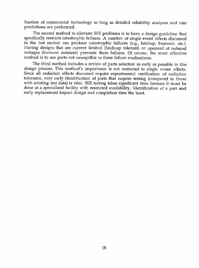
fraction of commercial technology as long as detailed reliability analyses and ratepredictions are performed.
The second method to alleviate SEE problems is to have a design guideline thatspecifically restricts catastrophic failures. A number of single event effects discussedin the last section can produce catastrophic failures (e.g., latchup, burnout, etc.).Having designs that are current limited (latch-up tolerant) or operated at reducedvoltages (burnout resistant) prevents these failures. Of course, the most effectivemethod is to use parts not susceptible to these failure mechanisms.
The third method includes a review of parts selection as early as possible in thedesign process. This method's importance is not restricted to single event effects.Since all radiation effects discussed require experimental verification of radiationtolerance, very early identification of parts that require testing (compared to thosewith existing test data) is vital. SEE testing takes significant time because it must bedone at a specialized facility with restricted availability. Identification of a part andearly replacement impact design and completion time the least.
18

CONCLUSIONS
This primer provides a brief survey of space radiation environments and theireffects on spacecraft electronics systems. Discussions of total ionizing dose anddisplacement damage show electronics have a cumulative damage mode thatcontinually increases over the lifetime of the spacecraft. The single event effectsdiscussion shows the radiation environment can impact a mission from the verybeginning and, without precaution, can cause catastrophic failure. From thediscussion of possible mitigation techniques, it is apparent that consideration ofthese environments early in the design process is a necessity.
The early involvement of radiation specialists in mission planning, systemdesign, and design review (part-by-part verification) is a must. During the missionplanning phase environment prediction gives an early indication of problems themission may encounter. Additionally, orbit optimization minimizes the impact ofthe radiation environment on mission goals.
Equally important is early involvement by these specialists in initial systemdesigns. Improvements in circuit designs can be easily incorporated to mitigatecertain radiation effects. Also, electronic box designs can be optimized. Intelligentplacement of susceptible electronic components takes advantage of existingshielding (hiding a TID sensitive part behind a large transformer). Placing local spotshields minimizes the size and weight required to achieve required shielding.Systems are optimized with respect to radiation effects and weight by such prudentplacements.
In the design review, a part-by-part verification ensures all electronics meetprogram design guidelines and specifications. While this task may seem formidableinitially, if mission planning and system design are accomplished, the work shouldproceed with no surprises. Granted the space radiation environment does presentsdesign concerns but they can be addressed and systems designed to withstand them.
Questions or comments should be directed to the MSFC Electromagnetics andAerospace Environments Branch, Steven D. Pearson, 256-544-2350.
19

GLOSSARY
annealing The process associated with the change in electrical ormaterial characteristics, induced by radiation, due to theeffects of time and temperature. The normal connotation isan improvement in the characteristics, but in the case oftotal ionizing dose, this is not always the case.
burnout A catastrophic failure of a high power transistor caused bytransient radiation. In the space environment a single ioncan induce a degenerative feedback current in the transistorthat will lead to its failure due to excessive current.
dark current The leakage current associated with the cells of a CCD array.A high level of this background current tends to make theimage turn dark.
diode A two terminal electronic device that allows current flow in
only one direction. Applying voltage of one polarity inducesa current whose level is exponentially related to the voltage.Applying voltage of the opposite polarity allows no currentflow in the forward direction, but allows a very smallreverse current called leakage current.
displacement damage The damage that occurs to a material, which has awell-ordered crystalline lattice structure, that is disturbed byradiation displacing some of the lattice elements.
dose The energy absorbed per unit mass from any radiation inany material. This indicates the amount of energytransferred to the material through which the radiation ispassing. The most common unit is the rad, which is thedeposition of 100 ergs per gram of material. The SI unit,however, is the Gray (Gy), which is 1 J/kg or 100 rad.
electron The fundamental atomic building block particle with a netcharge of negative one.
electron volt The kinetic energy an electron gains by its accelerationthough a potential difference of one volt.
energy When used in the radiation effects area, the energy refers tothe kinetic energy the particle has, which is directly relatedto the square of the velocity of the particle. Typical unit usedis MeV.
fluence The number of particles passing through a given area. Thefluence is the time integrated flux. Typical unit is cm "2.
20

flux The number of particles passing through a given area perunit time. Typical units are cm2-sec 1.
gate rupture A catastrophic failure of a high power transistor caused bytransient radiation. In the space environment a single ioncan induce sufficient charge buildup and discharge occursacross the gate of the transistor. A short circuit develops andthe transistor fails.
heavy ion The atomic nucleus of an element greater than hydrogenwith a number of electrons less than the electrically neutralatom. The difference between the number of electrons
present and the number in the neutral state is called thecharge state of the heavy ion.
horns The region of the outer electron belt that, due to the bendingof the Earth's magnetic field at the higher latitudes, exists atlow altitudes. These regions can be a significant source ofdose for spacecraft in low-Earth orbit with high inclinations.
latchup A destructive, high current mode of operation that CMOSstructures can transfer into if the parasitic structures existand the radiation induced transient currents are sufficientlyhigh. If not current limited, due to the current feedback andtemperature effects, the current will continue to increaseuntil the part fails from overcurrent.
LET The linear energy transfer is that amount of energy anincident particle will transfer, locally, to a given material perunit distance. Typical units are MeV-cm2/mg.
mil A distance unit equal to 1/1000 of an inch.
photons A radiation type that is electromagnetic energy thatquantum mechanically interacts as both a wave packet andparticle.
proton The fundamental nuclear building block particle with a netcharge of positive one. A proton is also the nucleus of ahydrogen atom.
rad Unit of absorbed dose equal to 100 ergs/gm.
rad-hard Terminology that indicates the electronic component designwas modified to ensure radiation reliability andsurvivability. This category is sometimes divided intomilitary and space qualifications, where the militaryqualification also indicates a nuclear weapon survivabilityspecification.
rad-tolerant Terminology that indicates the electronic component designwas not modified to ensure radiation reliability and
21

survivability but has a significant level of tolerance toradiation inherently in its design.
SEE A single event effect is an effect in an electronic device thatis induced by the passage of a single ionizing particlethrough its structure. The effects can vary from simple bitflips to catastrophic failures.
TID The total ionizing dose is the cumulative buildup of dosethat produces effects in electronics by ionization of thematerials in the device.
upset The most common form of single event effect. In digitalmicroelectronics, information is stored as a zero or one. Anupset is the transition from one to the other (i.e., zero to oneor one to zero).
Van Allen Belts The region of space where the Earth's magnetic field has"trapped" radiation. Due to the dipole nature of the Earth'smagnetic field and the intensity variation with altitude, anycharged particle that enters into this region will continuallytravel along the lines of force, effectively "trapping" theparticle.
22

REFERENCES
1. Webb, R.C., Palkuti, L., Cohn, L., Kweder, G., and Costantine, A.: "TheCommercial and Military Satellite Survivability Crisis." Defense Electronics, August1995.
2. PL-GEOSpace Version 1.21, USAF Phillips Laboratory/GPSP, March 1996.
3. Picture was designed and drawn by E.G. Stassinopoulos.
4. Adapted from "The Space Radiation Environment for Electronics," E.G.Stassinopoulos and J.P. Raymond, Proc. of the IEEE, Vol. 76, No. 11, 1988.
5. Wallmark, J.T. and Marcus, S.M.: "Minimum Size and Maximum PackingDensity of Non-Redundant Semiconductor Devices," IRE Proc., 50, 286, 1962.
23

REPORT DOCUMENTATION PAGE FormApprovedOMB No. 0704-0188
Public reporting burden for this collection of information is estimated to average 1hour per response, including the time for reviewing instructions, searching existing data sources,gathering and maintaining the data needed, and completing and reviewing the collection of information. Send comments regarding this burden estimate or any other aspect of thiscollection of information, including suggestions for reducing this burden, to Washington Headquarters Services, Directorate for Information Operation and Reports, 1215 JeffersonDavis Highway, Suite 1204, Arlington, VA 22202-4302, and to the Office of Management and Budget, Paperwork Reduction Project (0704-0188), Washington, DC 20503
1. AGENCY USE ONLY (Leave Blank) 2. REPORT DATE 3. REPORT TYPE AND DATES COVERED
July 1999 Technical Publication4. TITLE AND SUBTITLE 5. FUNDING NUMBERS
Spacecraft Environments Interactions: Space Radiation and ItsEffects on Electronic Systems
6. AUTHORS
J.W. Howard Jr.* and D.M. Hardage
7. PERFORMING ORGANIZATION NAMES(S) AND ADDRESS(ES) 8. PERFORMING ORGANIZATIONREPORT NUMBER
George C. Marshall Space Flight Center
Marshall Space Flight Center, Alabama 35812 M-929
9. SPONSORING/MONITORING AGENCY NAME(S) AND ADDRESS(ES) 10. SPONSORING/MONITORINGAGENCY REPORT NUMBER
National Aeronautics and Space Administration NASA/TP--1999-209373Washington, DC 20546-0001
11. SUPPLEMENTARY NOTES
Prepared for Systems Analysis and Integration Laboratory, Science and Engineering Directorate*Computer Sciences Corporation
12a. DISTRIBUTION/AVAILABILITY STATEMENT 12b. DISTRIBUTION CODE
Unclassified-Unlimited
Subject Category 18Standard Distribution
13. ABSTRACT (Maximum 200 words)
The natural space environment is characterized by complex and subtle phenomena hostile to spacecraft. Effects ofthese phenomena impact spacecraft design, development, and operation. Space systems become increasinglysusceptible to the space environment as use of composite materials and smaller, faster electronics increases. Thistrend makes an understanding of space radiation and its effects on electronic systems essential to accomplish overallmission objectives, especially in the current climate of smaller/better/cheaper faster.
This primer outlines the radiation environments encountered in space, discusses regions and types of radiation,applies the information to effects that these environments have on electronic systems, addresses design guidelinesand system reliability, and stresses the importance of early involvement of radiation specialists in mission planning,system design, and design review (part-by-part verification).
14. SUBJECT TERMS 15. NUMBER OF PAGES
radiation types, regions, environments, radiation effects categories, 32mitigation options, South Atlantic anomaly 16 PRICECODEA03
17. SECURITY CLASSIFICATION 18. SECURITY CLASSIFICATION 19. SECURITY CLASSIFICATION 20. LIMITATION OF ABSTRACT
OF REPORT OF THIS PAGE OF ABSTRACT
Unclassified Unclassified Unclassified UnlimitedNSN 7540-01-280-5500 Standard Form 298 (Rev. 2-89)
PrescribedbyANSIStd.239-18


National Aeronautics and
Space Administration 3 1176 01447 1313AD33
George C. Marshall Space Flight CenterMarshall Space Flight Center, Alabama35812