30c, 40c, 50c & 60c open flue gas fired boileracwilgar.co.uk/boiler-manual-pdf/potterton... ·...
TRANSCRIPT

30C, 40C, 50C & 60Copen flue gas fired boiler
FOR USE WITH NATURAL GAS (G20) ONLYRead these instructions thoroughly before working on the boiler.Leave the instructions adjacent to the gas meter.

2
GENERAL - Page 2
GAD (90/396/EEC)
POTTERTON PRIMA 30C G.C. No. 41.605.90POTTERTON PRIMA 40C G.C. No. 41.605.91POTTERTON PRIMA 50C G.C. No. 41.605.92POTTERTON PRIMA 60C G.C. No. 41.605.93
IMPORTANT
This appliance must be installed by a competent person as stated in the Gas Safety (Installation and Use) Regulations 1994.
Prima boilers are certified for safety, it is therefore important that no external control devices (eg. flue dampers, economisersetc.) be directly connected to these appliances unless covered by these installation instructions or otherwise recommendedin writing. Any direct connection of a control device not approved by Potterton Myson could invalidate the certification andthe normal warranty.
LIST OF CONTENTS
General Page No. 2 Installation Instructions Page No.13Accessories Page No. 3 Commissioning Page No.19Installation Data Page No. 3 Servicing Instructions Page No.21Boiler Dimensions Page No. 3 Health and Safety Information Back PageSite Requirements Page No. 5 Control Systems } Supplied inTechnical Data Page No. 7 Pipework and Wiring Guide } Literature pack
Users Instructions }
GENERAL
Once the pilot has been lit Potterton Prima C boilers areautomatic in operation. They are wall mounted naturaldraught open flue appliances using a cast iron heatexchanger and are available in four outputs ranging from5.86-17.58kW (20,000-60,000 Btu/h).
The boilers which are designed to provide domestic hotwater and/or central heating must be used on INDIRECT hotwater systems only.
The cast iron heat exchanger is suitable for use on openvented gravity hot water/ pumped central systems or fullypumped systems which may be sealed or open vented.

3
ACCESSORIES - Page 3
The following range of Potterton Myson system controls arealso available and further information will be provided onrequest.Electronic Programmer EP2001, EP3001, EP4001, EP5001and EP6000.Programmable Electronic Thermostat PET1
Thermostatic Radiator Valve.Electronic Cylinder Thermostat PTT2 or PTT100Electronic Room Thermostat PRT2 or PRT100Motorised Zone Valve MSV222 or MSV228Motorised Diverter Valve MSV322
INSTALLATION DATA - Page 3
The installation of the boiler must be in accordance with thelatest relevant requirements of the Gas Safety (Installationand Use) Regulations 1994, local building regulations, IEEWiring Regulations and the byelaws of the local WaterUndertaking.
Detailed recommendations are contained in the followingBritish Standard Codes of Practice:-
BS6798. BS5440 Part 1.BS5440 Part 2. BS55449 Part 1.BS5546, BS4814,BS6891 BUILDING REGULATIONS.MODEL WATER BYELAWS.BRITISH GAS PUBLICATION DM2.GAS SAFETY (INSTALLATION AND USE) REGULATIONS1994.BUILDING STANDARDS (SCOTLAND)REGULATIONS.
BOILER DIMENSIONS - Page 3
Figure 1 BOILER DIMENSIONS (mm)

4
GENERAL ARRANGEMENT - Page 4
Figure 2 - GENERAL ARRANGEMENT

5
SITE REQUIREMENTS - Page 5
These boilers are not suitable for external installation. Theappliance must not be installed in bathrooms, shower rooms,bedrooms, bed-sitting rooms, garages or rooms where highlyinflammable materials or vapours are likely to be present.Fitting in toilets or cloakrooms is not recommended but ispermitted, provided the combustion air is taken direct fromoutside. Where installation of the boiler will be in an unusuallocation special procedures may be necessary and BS6798gives detailed guidance in this aspect.
Ensure that the gas supply pipe and meter are large enoughfor this appliance and any others that may be run off thesame meter. Reference should be made to BS6891
Boiler Mounting Surface.The boiler must be mounted on a flat wall, which may be ofcombustible material and must be sufficiently robust to takethe weight of the boiler. It is recommended that any wallcovering behind the boiler that may discolour should beremoved before mounting the boiler. The requirements of thelocal authorities and the Building Regulations must beadhered to.
IMPORTANT NOTICE:TIMBER FRAMED HOUSESIf the appliance is to be fitted in a timber framed building, itshould be fitted in accordance with British Gas Publication‘Operational Procedures for Customer Service’ Part 19. If inany doubt, advice should be sought from the local region ofBritish Gas.
Clearances Around the BoilerThis appliance must at all times be fitted more than 100mm(4in) above floor level.The following minimum clearances must be maintained afterinstallation for correct operation and servicing of the boiler:-610mm (2ft) at the front of the boiler.5mm (0.2in) each side of the boiler.100mm (4in) at the top.100mm (4in) at the bottom where fitted above a workingsurface etc.Additional clearances to these may be required forinstallation and are left to the discretion of the installer.
Combustion Air and Ventilation RequirementsGeneral recommendations are given in BS5440 Part 2, andthe following notes are given as a general guide.
1. Ventilation of Compartments containing Gas BoilersTHE 60C IS NOT SUITABLE FOR INSTALLATION IN ACOMPARTMENT.
For other models there should be two permanent air vents,one at low level and one at high level. Each opening,whether left free or furnished with a grille, must have aminimum effective area in accordance with Table 1.
TABLE 1
Level of Area for air whether takenAir Vent from a Room or Outside
sq. in. sq. cm.
30C High 38 245Low 38 245
40C High 52 335Low 52 335
50C High 66 425Low 66 425
There must be at least 300mm (l2in) clearance between thegrille on the front of the boiler casing and any internalsurface of the cupboard to allow for adequate air foroperation of the draught diverter.Further details for installation of a boiler within acompartment are given in BS6798.
2. Ventilation of rooms containing Gas Boilers.
The ventilation of the room containing the boiler shall includeair for combustion and draught diverter dilution. This appliesalso when the boiler is sited in a compartment, unless the airvents are both direct from outside.A permanent air vent shall be provided in an outside wall ofthe building at either high or low level.

6
SITE REQUIREMENTS - Page 6
This opening may be:a Directly into the room or space containing the boiler or,b Via a duct through the wall or roof of the room, (where
such a method is considered British Gas should beconsulted) or,
c Into an adjacent room or space which has an internalpermanent air vent of the same size to the roomcontaining the boiler. It is undesirable to ventilate via akitchen, bathroom or toilet.
The air vent should be sited as far as possible from anyextract fan to avoid short circuiting. To avoid the possibility offreezing water pipes, the vent should not be sited near pipes.The minimum effective area of the permanent air vent mustbe:
30C 22 sq cm 3.4 sq in40C 39 sq cm 6.0 sq in50C 56 sq cm 8.7 sq in60C 74 sq cm 11.5 sq in
If the room (e.g. kitchen) from which air is drawn, has anextract fan fitted, then the opening size of the permanent airvent should take this into account to ensure that theoperation of the boiler flue is not adversely affected when theextract fan is running with all doors and windows closed.This should be checked in accordance with BS5440 Parts 1and 2.
3. Grilles and Ducts
Any grille and/or duct should be so sited and of a type not tobecome easily blocked or flooded and should offer lowresistance to air flow.
FLUEA 100mm (4in) internal diameter flue must be connected tothis appliance to evacuate the products of combustion fromthe boiler. The flue
connecting socket on the boiler is designed to accept fluepipe to BS567.If a fluepipe to BS715 is to be used an adaptor must be fittedto the boiler connecting socket.Reference should be made to The Building Regulations andBritish Standard 5440 Part 1. The following notes have beencompiled for your guidance:-a The flue pipe should be at least 25mm from any
combustible material, or when passing through a wall,floor or roof, be separated from any combustiblematerial by a non-combustible sleeve enclosing an airspace of at least 25mm around the flue pipe.
b Ideally a flue should rise vertically to a termination pointwhich is unaffected by down draught or wind eddies.Therefore, for practical purposes, the flue should havethe shortest run possible; 90° bends should be avoided.The terminal should be at least above roof edge leveland must be of a type acceptable to British Gas.
c Wherever possible there should be at least 600mm (2ft)of vertical flue from the boiler flue socket.Note; A split socket should be fitted in this length.
d Horizontal runs should be avoided. If a near horizontallength is unavoidable, it must be followed by at leasttwice that length of vertical flue.
e Wherever possible internal stacks, lined if necessary,should be used.
f All brick chimneys must be lined with a liner acceptableto British Gas.
g Where condensation is likely a means of draining mustbe provided.
h If an existing flue is being used, ensure that it has beenthoroughly swept before lining or connecting the boiler.

7
ELECTRICITY SUPPLY - Page 7
A 240 volts ~ 50Hz. single phase electricity supply fused at3A must be provided in accordance with the latest edition ofthe lEE wiring regulations and any other local regulationsthat may apply. The current rating of the wiring to the boilermust exceed 3 amperes and have a cross sectional area ofat least 0.75mm2 in accordance with BS6500 1990 Table 16.The method of connection to the electricity supply MUSTfacilitate complete isolation of the appliance, preferably bythe use of a
fused three pin plug and unswitched, shuttered socket outlet,both complying with the requirements of BS1363.Alternatively, connection may be made via a fused doublepole isolator having a contact seperation of 3mm in all polesand serving the appliance and system controls only.
TECHNICAL DATA - Page 7
Boiler Type B11Bs
Maximum Working Head 30.5m (l00ft)
Minimum Working Head (Fully pumped systems) 150mm (6in)
Minimum Circulating Head (Gravity systems) 1.2m (4ft)
Gas Supply Pressure 20 mbar
Maximum Flow Temperature 82°C
Electricity Supply 240v ~ 50Hz fused at 3A
Flow/Return Connection 28mm copper
Gas Supply Connection Rc, ½ (½ in BSP Female)
Power Consumption 20 watts
30 & 40 model 50 & 60 model
Water Content 1.8 litre 2.5 litre0.4 gal 0.55 gal
Appliance Weight - installed 36.3 kg 44.0kg80.0 lbs 97.0 lbs
Appliance Weight - lift 31.0kg 38.5 kg
BOILER INJECTOR GAS RATE INPUT OUTPUT BURNER PRESSURE
SIZE SIZE m3/h (ft3/h) Kw(Btu/h) kW(Btu/h) Mbar in wgMin 0.76 (26.84) 8.20 (27978) 5.86 (20,000) 7.8 3.1
30 2.6mm 0.95 (33.54) 10.18 (34734) 7.33 (25,000) 11.8 4.7Max 1.09 (38.49) 11.72 (40000) 8.79 (30,000) 15.7 6.3Min 1.15 (40.51) 12.29 (41930) 8.79 (30,000) 9.5 3.8
40 3.1mm 1.33 (46.98) 14.25 (48620) 10.26 (35,000) 12.7 5.1Max 1.46 (51.49) 15.62 (53295) 11.72 (40,000) 15.3 6.1Min 1.47 (51.90) 15.74 (53700) 11.72 (40,000) 9.3 3.8
50 3.55mm 1.65 (58.36) 17.70 (60400) 13.19 (45,000) 11.6 4.7Max 1.81 (64.00) 19.41 (66225) 14.7 (50,000) 14.2 5.7Min 1.86 (65.68) 19.9 (68000) 14.7 (50,000) 10.8 4.3
60 3.8mm 2.01 (70.97) 21.60 (73800) 16.12 (55,000) 13.0 5.2Max 2.17 (76.62) 23.3 (79500) 17.6 (60,000) 15.2 6.1

8
TECHNICAL DATA - Page 8
Circulation Pump Selection
The resistance through the heat exchangers when operatingwith a water flow rate producing an 11°C temperature rise atmaximum boiler output is shown in TABLE 2. If othercontrols, such as three-position valves are used in thesystem, the resistance through them, quoted in theirmanufacturers literature must be taken into account. Thepump may be fitted on either the flow or return and onFULLY PUMPED systems MUST be wired directly to theboiler terminal block, see Fig 14.It must be fitted with twoisolating valves which are positioned as close to the pumpas possible. Isolation of the valves must always leave theopen vent unobstructed.
TABLE 2

9
TECHNICAL DATA - Page 9
THE SYSTEM
The boiler must be used on INDIRECT hot water systemsonly. It is suitable for use on open vented gravity hotwater/pumped central heating systems or fully pumpedsystems which may be sealed or open vented
The system should be designed so that the maximum statichead does not exceed 30.5m (l00ft) and a minimum on fullypumped systems of 150mm (6in). See Fig 4.Gravity domestic hot water circuits should have a minimumcirculating head of 1.2m (4ft). See Fig 5. Excessivehorizontal runs should be avoided, but if this is not possiblethe circulating head should be increased.
If the boiler is to be used on a system with gravity hot waterthe bulb of the overheat thermostat should be repositionedas shown on Fig 2.
To prevent reverse circulation in the gravity circuit when thepump is running an injector disc is provided to form aninjector tee at the return connection on the boiler. SeeFig 11.
To prevent nuisance operation of the overheat thermostat, itis important that where electrically operated zone valves areused the boiler is wired so that it does not cycle when thezone valves are closed. Also systems fitted with controls thatclose both hot water and central heating circuits while theboiler is still hot must be fitted with a by-pass circuit todissipate the residual heat within the boiler.
Further information on by-pass arrangements is provided inlater notes and illustrations.
Drain-off taps should be fitted in the pipework close to theboiler and in low points in the system.
NOTE
Although the system can be emptied using the drain-off tapsin the pipework around the system, to empty the boiler it isnecessary to remove the drain-off plug situated in the returnheader at the lower right-hand side of the casting. See Fig 2.
COMBINED GRAVITY HOT WATER AND PUMPEDCENTRAL HEATING SYSTEMS
Where a cylinder thermostat and zone valve are fitted tocontrol the temperature of the domestic hot water it isrecommended that a by-pass be installed
in the gravity circuit. A suggested method of doing this isshown in Fig 5 where the bathroom radiator is connectedinto the gravity circuit and is fitted with two lockshield valves.Mechanically operated thermostatic domestic hot watertemperature control valves which allow the boiler to operatewhen the valve is closed MUST NOT BE FITTED.
FULLY PUMPED SYSTEMS
The pump must always be wired directly to the boilerterminal block as shown in Fig 13.
If a three port diverter valve is used as shown in Fig 4 a by-pass is not necessary since one circuit is always open.
Where a pair of two port valves are used, a by-pass isnecessary. The total length of the by-pass circuit taken fromthe boiler connections should be greater than 4 metres of22mm pipe. It should be fitted with a lockshield valve andadjusted to maintain a minimum flow through the boiler of4.5 litres/min (1 gal/mm), see Figs 4 & 6.
Systems fitted with controls which allow the boiler to operatewhen both the hot water and central heating circuits areclosed (i.e. mechanically operated thermostatic controlvalves) must be fitted with a by-pass circuit capable of:-
1. Dissipating a minimum of 1 kw (3400 Btu/h).
2. Maintaining a minimum water flow through the boiler of 9litres/min (2 gal/min).
A suggested method of meeting these requirements by usinga bathroom radiator fitted with two Iockshield valves isshown in FIGS. 4,6.
Additional system information can be found in the ControlSystems, Pipework and wiring guide.
SEALED SYSTEMS (FULLY PUMPED)
The installation must comply with the requirements ofBS6798 and BS5449 Part 1. The ‘British Gas publicationBritish Gas Specification for Domestic Wet Central HeatingSystems’ should also be consulted.
Safety Valve
A non-adjustable spring-loaded valve, pre-set to operate at3bar (45lbf/in2) shall be used. It must comply with BS6759Part 1 and include a manual

10
TECHNICAL DATA - Page 10
testing device. It shall be positioned in the flow pipe eitherhorizontally or vertically upwards and close to the boiler. Noshut-off valves are to be placed between the boiler andsafety valve. The valve shall be installed into a dischargepipe which permits the safe discharge of steam and hotwater such that no hazard to persons or damage to electricalcomponents is caused.
Pressure Gauge
A pressure gauge incorporating a fill pressure indicator,covering the range 1-4bar (60lbf/in2) shall be fitted to thesystem. It should be connected to the system, preferably atthe same point as the expansion vessel. Its location shouldbe visible from the filling point.
Expansion Vessel
A diaphragm-type expansion vessel to BS4814 Part 1 shallbe fitted close to the inlet side of the pump. The connectingpipework should not be less than 15mm (½ in nominal).Pipework connecting the expansion vessel should notincorporate valves of any sort. Methods of supporting thevessel are supplied by the manufacturer. The nitrogen or aircharge pressure of the expansion vessel shall not be lessthan the hydrostatic head, (height of the top of the systemabove the expansion vessel). To size the expansion vessel itis first necessary to calculate the volume of water in thesystem in litres. The following volumes may be used as aconservative guide to calculating the system volume.
Boiler Heat Exchanger 6.5 litresSmall Bore Pipework 1 litre per kW of
system outputMicro Bore Pipework 7 litresSteel Panel Radiators 8 litres per kW of
system outputLow Water CapacityRadiators 2 litres per kW of
system outputHot Water Cylinder 2 litres
If the system is extended, the expansion vessel may have tobe increased unless previous provision has been made forthe extension. Where a vessel of the calculated size is notavailable, the next available larger size should be used.
The boiler flow temperature is controlled at approximately82°C.
The vessel size can now be determined from the followingtable where V = System volume in litres.
Vessel Charge 0.5 .0Pressure (bar)Initial SystemPressure (bar) 0.5 1.0Expansion VesselVolume (litres) V x 0.833 V x 0.11
This is a general guide; if it is required to be more accuraterefer to BS7074.
Cylinder
The hot water cylinder must be an indirect coil type or adirect cylinder fitted with an immersion calorifier suitable foroperating at a pressure of 0.3bar (5lbf/in2) in excess ofsafety valve setting. Single feed indirect cylinders are notsuitable for sealed systems.
Method of Make-Up
Provision shall be made for replacing water loss from thesystem either:-
i) from a make-up vessel or tank mounted in a positionhigher than the top point of the system, and connectedthrough a non-return valve to the system on the returnside of all heat emitters.
or
ii) Where access to a make-up vessel would be difficult byusing the mains top up method or a remote automaticpressurisation and make-up unit as illustrated in Fig 6METHODS 1 & 2.
Mains Connection
There shall be no connection to the mains water supply or tothe water storage tank which supplies domestic water eventhrough a non-return valve, without the approval of the localWater Authority.
Filling Point
The system shall be fitted with a filling point at low levelwhich incorporates a stop valve to BS1010 and a doublecheck valve (approved by the National Water Council) to befitted in this order from the system mains. Refer to Fig 6METHOD 1.

11
TECHNICAL DATA - Page 11
Figure 4 OPEN VENTED FULLY PUMPED SYSTEM WITH A COMBINED FEED AND VENT
Figure 5 OPEN VENTED GRAVITY DOMESTIC HOT WATER PUMPED CENTRAL HEATING

12
TECHNICAL DATA - Page 12
Figure 6 FULLY PUMPED SEALED SYSTEM

13
INSTALLATION INSTRUCTIONS - Page 13
It is the law that all gas appliances are installed and servicedby competent persons as stated in the Gas Safety(Installation and Use) Regulations 1994.
Electrical installation and servicing should be carried out bya competent person in accordance with the I.E.E. WiringRegulations
For Health and Safety information see back page.
The boiler and its associated equipment will arrive on site inone cardboard carton. The contents of the carton is asfollows:-
BoilerTemplateBoiler Mounting PlateLiterature Pack containing:
Installation & Servicing InstructionsUsers InstructionsControl System Pipework and Wiring Guide
Auxilliary Pack containingGas Service CockAccessory PacksAdjustment screws
Figure 7 TEMPLATE
Place template in proposed boiler position taking dueaccount of the information given previously and the positionof the flue, (the minimum side clearances are automaticallyallowed for). Refer to page 5 for top and bottom clearanceswhich can be measured from the template. Ensure that thetemplate is level and mark hole positions ‘B’.
If the flue is to rise through the ceiling, mark out centre lineof hole for flue by extending the dotted line on templatevertically and measure out 158mm from rear wall asillustrated.
Figure 8 SECURING BOILERMOUNTING PLATE
Remove template and drill holes ‘B’ to a depth of 50mmusing a 7mm drill. Cut hole through wall or ceiling asnecessary for intended run of flue pipe.
Using wall plugs, screws and washers (accessory pack A)attach boiler mounting wall plate to wall ensuring that it islevel.

14
INSTALLATION INSTRUCTIONS - Page 14
Figure 9 PREPARING BOILER
The controls cover should have been removed whenunpacking the boiler, if not pull controls cover forward 25mm,lower to release from the four side fixings and pull forwardclear of the thermostat knob
Remove door by undoing the two lower fixing screws and liftdoor off the two upper hinge brackets.
Engage adjustment screws into the boiler legs but do notscrew in fully at this stage

15
INSTALLATION INSTRUCTIONS - Page 15
Figure 10 LIFTING AND ALIGNING BOILER
Lift boiler onto the mounting bracket and adjust the boilerposition to obtain a minimum of 5mm clearance from anyside wall or cupboard.
Secure boiler to the mounting bracket using 5mm screw fromaccessory pack A.
Undo the screws securing the transportation feet. Discardfeet and screws.
Correct vertical alignment with rear wall as necessary usingthe adjustment screws
Remove the temporary cardboard packing pieces from eitherside of the casing
Remove the four securing screws and withdraw the innerdraught diverter assembly. Check that the flueway bafflesare correctly located and retained in the flueways as shownin Fig 10. Reassemble the draught diverter.
Make the flue connection to the boiler draught divertersealing the joint with a suitable compound. Refer to thenotes under FLUE page 6.
The weight of the flue must be supported independentlyNOT by the boiler.

16
INSTALLATION INSTRUCTIONS - Page 16
Figure 11 PIPE CONNECTIONS
Connect the system pipework to the boiler, compressionfittings are recommended. If however, capillary fittings areused, it is essential to temporarily remove the thermostatbulb from the flow pipe before soldering.
A drain off tap should be installed close to the boiler if it is ina low point of the system.On combined gravity hot water/pumped central heatinginstallations the flow and return pipes for both the gravity hotwater circuit and pumped central heating circuits must beconnected to tees fitted directly to the flow and return pipeson the boiler.
The gravity circuit should be installed in 28mm copper pipe.28mm tees should be used.
The injector disc (accessory pack G) must be positioned inthe pumped return branch of the tee as illustrated in Figs 11& 11B.
Remove gas service cock from the auxilliary pack and attachit to the union nut on the inlet to the gas assembly.
With the inlet connection of the gas service cock facing therear, connect the gas supply pipe.
Figure 11B WARNING: UNDER NOCIRCUMSTANCES SHOULD A‘REDUCING SET’ BE FITTED
Figure 12
NOTEThe boiler is despatched with the overheatThermostat bulb positioned for FULLY PUMPED OPENVENTED OR SEALED SYSTEMS.
ONLY if the boiler is to be used on a GRAVITY DHW systemshould the bulb of the overheat thermostat be repositionedas described below, to prevent nuisance operation of theoverheat thermostat.
Remove clip securing overheat thermostat bulb to the flowpipe.
Uncoil the thermostat capillary and route it through the tworetaining clips attached to the front flange on the top panel.Position the thermostat bulb in the indent in the return pipeand secure in this position using the clip previously removed.

17
INSTALLATION INSTRUCTIONS - Page 17
Figure 13 PRINCIPAL OF WIRING
WIRINGWARNING: This appliance must be earthed.The boiler and all external control circuit wiring must besupplied from the same single isolating switch and should befused at 3A.
Care must be taken to ensure that all wiring to the boiler iskept clear of sharp edges and hot surfaces.
Ensure that the earth conductor is longer than the L, N, andSWL from the point of anchorage, so that the currentcarrying conductors become taut before the earth conductor,if the cable is pulled out of the cable clamp.
The boiler terminal block which is situated in the control boxis not designed to accept wiring from all the on site controlsand therefore the installer will usually need to incorporate asuitable junction box or Potterton Electronic Programmer.
The principle of wiring is shown in Fig 13. It should be notedthat the pump must be wired directly to the boiler terminalblock on FULLY PUMPED systems and to the junction boxor programmer on combined GRAVITY HOTWATER/PUMPED CENTRAL HEATING systems.
Figure 14 ACCESS TO THE BOILERELECTRICAL TERMINAL BLOCK
Remove control box securing screw and lower the controlbox to gain access to the boiler terminal block.
Figure 15 WIRING THE BOILERFOR A FULLY PUMPED SYSTEM
Route a four core cable through the plastic bush at the rearof the control box and the cable clamp as illustrated Fig 15,and connect it to the boiler input terminals as follows:-
Permanent live to terminal marked MAINS ‘L’Neutral to terminal marked MAINS ‘N’Earth to terminal marked MAINS +Switched live from external controls to terminal markedMAINS SwL.
If there are no secondary controls fitted connect the SwLterminal to permanent live in the external junction box.
Secure the cable within the cable clamp by tightening thesecuring screws.
Following the pump manufacturers instructions connect thepump supply wires to terminals marked PUMP, L, N and 4”on the boiler terminal block.
Route the cable through the plastic bush in the rear of thecontrol box and cable clamp as illustrated Fig 15. Securecable in cable clamp by tightening the two securing screws.
Close control box and replace securing screw.

18
INSTALLATION INSTRUCTIONS - Page 18
Figure 16 WIRING THE BOILER FORCOMBINED GRAVITY HOTWATER/PUMPED
CENTRAL HEATING SYSTEM
Route a three core cable through the plastic bush in the rearof the control box and the cable clamp as illustrated I Fig 16.Connect the cable to the boiler input terminals as follows:
Switched live on the GRAVITY DHW control circuit toterminal marked MAINS ‘SwL’Neutral to terminal marked MAINS ‘N’Earth to terminal marked MAINS
Secure the cable within the clamp by tightening the twosecuring screws.
The pump should be connected to PUMPED CENTRALHEATING control circuit at the junction box. See FIG. 13
Figure 17 FUNCTIONAL FLOW DIAGRAM
Figure 18 BOILER WIRING DIAGRAM

19
COMMISSIONING - Page 19
Open Vented SystemsRemove the pump and flush out the system thoroughly withcold water. Refit the pump, fill and vent the system andexamine for leaks.
Sealed SystemsThe system can be filled using a sealed system filler pumpwith a break tank or by any other method approved by thelocal Water Authority. Refer to FIG 6 and BS6798 1987.Remove pump and flush out the system thoroughly with coldwater. Re-fit the pump. Fill and vent the system until thepressure gauge registers 1.5 bar (22.5lbf/in2), examine forleaks. Raise the pressure until the safety valve lifts. Thisshould occur within ± 0.3 bar of the pre-set lift pressure of 3bar. Release water to attain the correct cold fill pressure.
All SystemsThe whole of the gas installation including the meter shouldbe inspected and tested for soundness and purged inaccordance with the recommendations of BS6891.Fit the case door into position by lifting it onto the top hingebrackets and secure it with the lower two fixing screws.
First LightingA. Ensure that the pump and radiator isolating valves are
open.B. Turn the boiler thermostat to the ‘0’ position.C. Turn on the main gas supply and the gas service cock
on boiler.D. Ensure that the time control, if fitted is in an ‘ON’
condition, and that the room and/or cylinder thermostats,where fitted are set to high temperatures.
E. Switch on the external electricity supply to the boiler. Inthe event of an electrical fault after installation of theappliance, preliminary electrical system checks must becarried out as described in the BG multimeter instructionbook. The checks to be carried out are:A - Earth Continuity, B - Short Circuit, C - Polarity, D -Resistance to Earth.
F. Partly depress and turn the gas control knob clockwiseensuring the symbol • lines up with the datum mark onthe gas valve body. See Fig 19. This ensures that thevalve is in the ‘OFF’ condition.
G. Partly depress and turn the control knob anti-clockwiseuntil the symbol * lines up with the datum mark on thegas valve body. Press and hold in the control knob andpress the spark generator button until a click is heard.Release the spark generator button and repeatoperation until the pilot ignites. See Figs 2&19. Hold inthe control knob for a further 15 seconds. On release thepilot should remain alight. Partly depress and turn thecontrol knob anti-clockwise until the symbol lines up withthe datum mark on the gas valve body.
NOTE:On first lighting, establishment of the pilot flame may beslightly delayed due to the presence of air in the pipework. Ifthe pilot fails to light or goes out at any time, immediatelyturn the control knob clockwise as far as possible, thenrelease it and wait three minutes before repeating thelighting procedure. The control knob should not be touchedduring this period.H. Turn the boiler thermostat on and to a high setting and
the main burner will light.I. Set the boiler thermostat and the room and/or cylinder
thermostat(s) and time control, where fitted, to theirrequired operating conditions.
J. After the boiler has operated for five minutes check thatthere is no spillage or leakage of combustion products inaccordance with BS5440 Part 1. Check soundness of allappliance gas carrying components and joints using leakdetection fluid and a mirror where necessary.
K. Switch off the boiler, using the thermostat knob.NOTE: If the main burner fails to light turn the boilerthermostat to the off position and check that the spillagedetector thermostat reset button (see Fig 18a) is pressed in,then repeat operation. If you have to keep resetting thethermostat, or the main burner fails to light consult the faultfinding chart on page 26, Fig 23.
Figure 18a

20
COMMISSIONING - Page 20
FINAL ADJUSTMENTA. Remove the screw from the burner pressure test nipple
on the gas control valve and fit a pressure gauge to thetest nipple. See Fig 19.
B. Turn on the boiler thermostat, then check that thepressure is in accordance with the values stated underTECHNICAL DATA. The burner pressure is factory setto the maximum stated.
C. If burner pressure adjustment is necessary, remove thescrewed cap from the gas control valve, see Fig 19, andturn the screw beneath clockwise to increase pressureand anti-clockwise to reduce pressure.
D. With the burner set to its correct pressure, the firing rategiven in TECHNICAL DATA should also be obtainedand this should be checked by meter reading 10 minutesafter the main burner has been lit.
E. Shut down the boiler, remove the pressure gauge.Replace the screwed cap and refit the screw in the testnipple. Re-light and test for gas soundness at the testnipple screw.
F. Remove the self-adhesive arrow from the inspectionticket tied to the burner supply pipe and stick it to theData Plate inside the controls cover to indicate theappropriate burner setting pressure. Refit the controlscover.
G. Heat the system to maximum. Check for water leaks,turn the boiler off, drain the system whilst hot.
H. Refill the system and on sealed systems adjust to thecorrect cold fill pressure. Set the pressure gauge pointerto the system design pressure.
I. If a by-pass circuit is fitted, the by-pass valve should beadjusted with the boiler operating under minimum loadconditions to maintain sufficient water flow through theboiler to ensure that the overheat thermostat does notoperate under normal operating conditions.
J. Remove the temporary label from the front of the casing,having checked compliance with the information itcontains
Figure 19 GAS CONTROL VALVE Figure 20 PILOT BURNER
Pilot BurnerThe pilot burner pressure is non-adjustable. The pilot flameshould heat the thermocouple so that the pilot safety deviceis “held in” but must not cause the thermocouple to glowbright red. Fig 20 illustrates the approximate size of a correctflame. The E.M.F. generated by the thermocouple should beof the order of 20-30 mV open circuit, 10-14 mV closedcircuit. Due to the voltage drop in the overheat thermostatcircuit there should be 6.5-8.5 mV closed circuit at theconnection to the gas control valve. Drop out should occurbetween 1-3 mV closed circuit. If these conditions cannot beachieved check that the inlet pressure is 20 mbar See Fig 19for inlet pressure nipple. If this is correct contact PottertonMyson.
Boiler ThermostatAt its minimum and maximum settings, the thermostatshould control the water flow temperature at approximately55ºC-82ºC (130ºF -180ºF). The thermostat has beencalibrated by the makers and no attempt should be made tore-calibrate it on site. Turn the thermostat to the ‘O’ positionand check that the main burner shuts down.
Pump Over-run Thermostat (Applicable on fully pumpedsystems only)The over-run thermostat will keep the pump running whenthe boiler has shut down, as long as the combustionchamber is hot.

21
COMMISSIONING - Page 21
Overheat ThermostatThe overheat thermostat is pre-set and no adjustment ispossible. It will require manual re-setting and the pilot re-lighting if an overheat condition occurs. The re-set buttoncan be found on the front of the controls box. See Fig 2.
Spillage Detector ThermostatThe Spillage Detector Thermostat (S.D.T.) is a manual resetthermostat that will trip out if flue products spill from thedown draught diverter.If you have to keep resetting the thermostat, consult the faultfinding chart on page 26, Fig 23.
Gas Control Valve1) Main Solenoid
Check the operation of the valve by turning off theelectricity supply, either by the isolating switch or timecontrol, where installed. The main burner must shutdown immediately.
2) Flame Failure ValveTurn the gas control knob to the ‘off’ position. The pilotmust shut down, and a “click” indicating thermocoupledrop out, should be heard within 60 seconds.
External ControlsCheck that any other external controls connected in thesystem such as time clocks and thermostats, control theboiler as required.
Users InstructionsA Users Instructions leaflet is provided with this boiler but thehouseholder must have the operation of the boiler andsystem explained by the Installer. The householder mustalso be advised of the importance of annual servicing and ofthe precautions necessary to prevent damage to the systemand building, in the event of the system remaining out ofcommission in frost conditions.
SERVICING INSTRUCTIONS - Page 21
Regular skilled servicing and cleaning of the appliance isessential to ensure continued safe and efficient operation.The frequency of cleaning will depend upon the particularinstallation conditions, and the use to which the appliance isput, but in general, once per year should be adequate.
It is the law that all gas appliances are installed and servicedby competent persons as stated in Gas Safety (Installationand Use) Regulations 1994.
Electrical installation and servicing should be carried out bya competent person in accordance with the I.E.E. WiringRegulations.
For Health and Safety Information see back page.
Servicing is best arranged by a contract placed withPotterton Myson Limited and further details are availablefrom the local Potterton Myson Service Department.
The boiler DATA PLATE and WIRING DIAGRAM areattached to the inside of the plastic controls cover. The boilerCODE NUMBER which should be quoted when orderingspares or requesting information is on the front of the controlbox.
The following notes apply to the boiler and its controls but itshould be remembered that attention must also be paid tothe heating circuit itself including radiator valves,thermostats, the time control and the expansion and feedwater system. It is advisable to clean the boiler immediatelyafter the end of the heating season.
In all cases prior to servicing, light up the boiler and checkthat the pilot and main burners have a clean, even flame andthat the gas rate and main burner pressure is correctly set.
Before the start of any servicing work, switch off at theexternal electricity supply by disconnecting the plug at thesocket or switching off external isolating switch. Turn off thegas service cock.
NOTE:After completing any servicing or replacement ofcomponents check for gas soundness and carry outfunctional checks.

22
SERVICING INSTRUCTIONS - Page 22
Figure 21 PREPARING THE BOILER FOR SERVICING
Figure 21B Figure 21C

23
SERVICING INSTRUCTIONS - Page 23
1. PREPARING THE BOILER FOR SERVICINGSee Fig 21A. Switch off the external electricity supply by
disconnecting the plug at the socket or switching offexternal isolating switch.
B. Remove controls cover by pulling it forward 25mm,lower it to release it from its four side fixings and pullforward clear of the thermostat knob.
C. Turn off the gas service cock.D. Remove door by unscrewing lower fixing screws and lift
door off the two upper hinge brackets.E. Remove the four securing screws and withdraw the
inner draught diverter assembly from the mouth of thedraught diverter. See Fig 21.
F. Remove retaining clips and lift out baffles from flueways,there are 3 baffles in 30 & 40 models and 4 baffles in 50& 60 models.
G. Remove four screws securing the lower combustionchamber front panel and remove panel.
2. MAIN BURNER REMOVAL AND CLEANINGA. Remove two screws securing pilot tube and
thermocouple sealing plate to boiler base.B. Remove two screws securing pilot to burner. Flex pilot
assembly forward and down.C. Remove two screws securing main burner to boiler
base.D. Slide main burner forward to disengage it from the rear
injector and lift out main burner.E. Unscrew the MS nut securing the burner cap and
remove end cap. Withdraw the internal baffle and gauzefrom within burner. See Fig 21. Thoroughly clean thegauze using a brush or vacuum cleaner. Clean alldeposits from the surface of the burner flame strip withsoft brush or vacuum cleaner and ensure there is no fluffin the entry of the burner venturi.
F. Remove main burner injector and ensure the orifice isclean.
G. PILOT BURNERThe following operations are only necessary if the pilotflame is distorted or the wrong size, i.e. too small.Disconnect the electrode lead from the electrode,uncouple the thermocouple and pilot gas tube nuts atthe base of the pilot assembly and lift out the pilot. Note,the pilot injector sits loosely on top of the pilot tube, ormay be retained in pilot head itself. Remove and inspectthe pilot injector for dirt deposits and clean if necessary.Likewise inspect and clean the electrode andthermocouple using a soft brush.
3. HEAT EXCHANGERWorking from above and below the heat exchanger usea suitable brush and remove all deposits from betweenthe fins. When cleaning the front flueway protect theinsulation inside the upper front panel by passing thefront baffle into the flueway as illustrated in FIG. 21 B.
4. COMBUSTION CHAMBER INSULATIONCheck the combustion chamber insulation for damage. Ifdamaged replace as described under replacement.
5. REASSEMBLYRefit the main burner ensuring it is correctly engagedonto the rear injector. Replacement of the othercomponents is the reverse of removal. Ensure that theflueway baffles are refitted as illustrated in Fig 21 andthe sealing plate and split grommets form a tight sealaround the pilot tube and thermocouple capillary.
6. Follow the full commissioning procedure as detailed inthe COMMISSIONING section of these instructions.
7. No further servicing is required on any other boilermounted units. Repair is by replacement.
8. FAULT FINDINGRefer to fault finding chart Fig 23 and wiring diagramFig 17.
9. REMOVAL/REPLACEMENT OF BOILER MOUNTEDUNITS
MAIN BURNERRefer to Fig 21 and carry out the following
A. Carry out operations A, B, C, D, G as described insection 1 PREPARING BOILER FOR SERVICE andoperations A, B, C, D described in section 2 MAINBURNER - REMOVAL AND CLEANING.
B. Replacement is the reverse of removal.C. Follow the full commissioning procedure as detailed in
the COMMISSIONING section of these instructions.
GAS CONTROL VALVEA. Carry put operations A, B, C in section 1 PREPARING
THE BOILER FOR SERVICE.B. Unplug the electrical lead from the gas valve.C. Disconnect the two blue wires from the thermocouple
interrupter connections.D. Disconnect the thermocouple lead from the interrupter
connection on the gas valve.NOTE: the interrupter connector is held in place by thethermocouple lead.
E. Disconnect the pilot tube at the gas valve.F. Undo the union at the gas service cock.G. Separate the gas control valve from the flange at the
outlet port by removing the four securing screws.H. Remove the screw securing the gas valve support
bracket to the boiler.I. Unscrew gas inlet assembly at valve and remove two
M4 screws retaining valve support bracket. Fit bothcomponents to new valve.
J. Replacement is the reverse of the removal. Use newsealing gasket on reassembly.
K. Follow the full commissioning procedure as detailed inthe COMMISSIONING section of these instructions

24
SERVICING INSTRUCTIONS - Page 24
PILOT FILTERThe pilot burner is protected from blockage by a pilot filtersituated within the gas control valve. The filter is large anddesigned to last the life of the gas control valve under normaloperating conditions. It is therefore unlikely to needreplacing. However in the event of pilot filter blockage beingsuspected the complete valve will need replacing.
THERMOCOUPLEa Carry out operations A, B, C, D in section 1
PREPARING BOILER FOR SERVICE.b Remove two screws securing pilot tube and
thermocouple sealing plate to boiler base.c Disconnect thermocouple lead from the interrupter
connection on the gas control valve and at the pilot.NOTE: The interrupter connector is held in place by thethermocouple lead. Withdraw thermocouple fromgrommet, noting the route the lead takes so that thereplacement can be routed in a similar manner toeliminate sharp bends.
d Replacement is the reverse of removal. Ensure onreassembly that the sealing plate and split grommetsform a tight seal around the pilot tube and thermocouplecapillary.
ELECTRODEa Carry out operations A,B,C,D in section 1 PREPARING
BOILER FOR SERVICE.b Pull off electrode lead from electrode.c Unscrew the nut securing the electrode to the pilot and
withdraw electrode.d Replacement is the reverse of removal.
COMBUSTION CHAMBER INSULATIONa To remove the insulation from the combustion chamber
sides, rear and lower front panel carry out operationsA,B,C,D,G in section 1 PREPARING BOILER FORSERVICE. If the insulation is to be removed from theupper front panel the main burner will also need to beremoved as described under MAIN BURNERREMOVAL & CLEANING, operations A,B,C,D.
b The side insulation panels are removed by sliding themfrom their retaining chanels.
c Once the side insulating panels have been removed therear insulation can be lifted out and the upper frontinsulation can be slid downwards from inside the panel.
d The lower front insulation is removed by bending backthe retaining tabs. Replacement is the reverse ofremoval. Follow the full commissioning procedure asdetailed in the COMMISSIONING section of theseinstructions.
SIGHT GLASSWARNING: GREAT CARE SHOULD BE TAKENWHEN HANDLING AND DISPOSING OF A BROKENSIGHT GLASS.a Carry out operations A,B,C,D in section 1 PREPARING
BOILER FOR SERVICE.b Remove three M4 nuts from sight glass retainer and
remove sight glass assembly.
c Replacement is the reverse of removal taking care thatthe clear circle in the sight glass lines up with the hole inthe combustion chamber door. NOTE: new gasketsmust be used when sight glass is fitted.
ELECTRODE LEADa Carry out operations A,B,C,D in section 1 PREPARING
BOILER FOR SERVICE.b Remove rear locking nut securing spark generator to its
mounting bracket, withdraw spark generator and pull offelectrode lead. Pull off electrode lead from electrode.Remove the split grommet and withdraw the electrodelead through the hole in the boiler base.
c Replacement is the reverse of removal.
SPARK GENERATORa Carry out operations A,B,C in section 1 PREPARING
BOILER FOR SERVICE.b Pull off electrode lead from spark generator, remove
rear locking nut securing spark generator to its mountingbracket and withdraw spark generator.
c Replacement is the reverse of removal.
PUMP OVER-RUN THERMOSTATa Carry out operations A,B,C,D in section 1
PREPARING BOILER FOR SERVICE.b Remove control box securing screw and lower control
box.c Access to the pump over-run thermostat is made easier
by separating the upper assembly of the control boxfrom the boiler base. This is done by removing the twohexagonal head screws identified in Fig 21 Tilt the upperassembly and disconnect the electrical wiring from thethermostat as follows:-Black from terminal 1Red from terminal 2Brown from terminal 3
d Replacement is the reverse of removal.e Follow the full commissioning instructions as
described in the COMMISSIONING section of theseinstructions.
BOILER THERMOSTATa Carry out operations A,B,C,D in section 1
PREPARING BOILER FOR SERVICE.b Remove control box securing screw and lower control
box.c Pull off the outer thermostat knob.d Remove inner thermostat post by undoing the two
securing screwse Access to the boiler thermostat is made easier by
separating the upper assembly of the control box fromthe boiler base. This is done by removing the twohexagonal head screws identified in Fig. 21.Tilt theupper assembly and disconnect the electricalconnections from the rear of the thermostat as follows:-White from terminal 3Brown from terminal 2Refer to Figs 17 & 18.
f Remove the nut securing the thermostat to the controlbox.
25
SERVICING INSTRUCTIONS - Page 25
g Remove the split pin retaining the thermostat bulb andwithdraw bulb from its pocket.
h Remove split grommet in the base of the boiler and thesplit grommet from the side of the control box, and feedthermostat capillary and bulb through holes.
I Replacement is the reverse of removal. The bulb of thenew thermostat should be coated with heat conductingpaste. Ensure the split grommet in the base of the boilermakes a good seal around the capillary.
j Ensure that the capillary is secure in the clips provided.Follow the full commissioning procedure as detailed inthe COMMISSIONING section of these instructions.
SPILLAGE DETECTOR THERMOSTATa Carry out operation A,B,C,D,E in section 1
PREPAIRING BOILER FOR SERVICE.b Remove the sensor from the support clips in the down
draught diverter and carefully remove the capillary fromthe support clips on the front edge of the casing.
c Carefully dislodge the split grommet from the base of theboiler and feed the capillary and bulb through the hole.
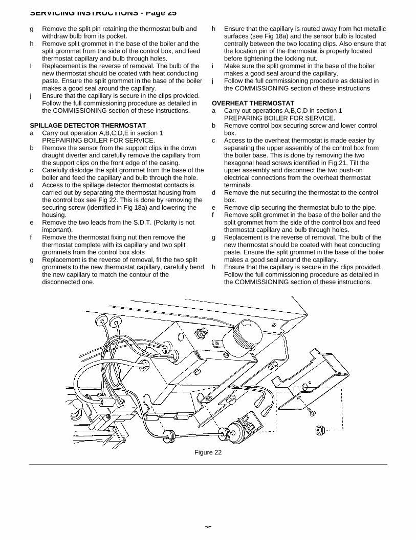
d Access to the spillage detector thermostat contacts iscarried out by separating the thermostat housing fromthe control box see Fig 22. This is done by removing thesecuring screw (identified in Fig 18a) and lowering thehousing.
e Remove the two leads from the S.D.T. (Polarity is notimportant).
f Remove the thermostat fixing nut then remove thethermostat complete with its capillary and two splitgrommets from the control box slots
g Replacement is the reverse of removal, fit the two splitgrommets to the new thermostat capillary, carefully bendthe new capillary to match the contour of thedisconnected one.
h Ensure that the capillary is routed away from hot metallicsurfaces (see Fig 18a) and the sensor bulb is locatedcentrally between the two locating clips. Also ensure thatthe location pin of the thermostat is properly locatedbefore tightening the locking nut.
i Make sure the split grommet in the base of the boilermakes a good seal around the capillary.
j Follow the full commissioning procedure as detailed inthe COMMISSIONING section of these instructions
OVERHEAT THERMOSTATa Carry out operations A,B,C,D in section 1
PREPARING BOILER FOR SERVICE.b Remove control box securing screw and lower control
box.c Access to the overheat thermostat is made easier by
separating the upper assembly of the control box fromthe boiler base. This is done by removing the twohexagonal head screws identified in Fig.21. Tilt theupper assembly and disconnect the two push-onelectrical connections from the overheat thermostatterminals.
d Remove the nut securing the thermostat to the controlbox.
e Remove clip securing the thermostat bulb to the pipe.f Remove split grommet in the base of the boiler and the
split grommet from the side of the control box and feedthermostat capillary and bulb through holes.
g Replacement is the reverse of removal. The bulb of thenew thermostat should be coated with heat conductingpaste. Ensure the split grommet in the base of the boilermakes a good seal around the capillary.
h Ensure that the capillary is secure in the clips provided.Follow the full commissioning procedure as detailed inthe COMMISSIONING section of these instructions.
Figure 22

26
SERVICING INSTRUCTIONS - Page 26Figure 23 FAULT FINDING CHART

27
SHORT PARTS LIST - Page 27
KeyNo
PMPart No
G.C.Part No
1 Pilot and electrode assembly S.l.T. (inc. items 2 - 6) 907241 337 8162 Pilot injector, 0.27mm S.I.T. 402892 395 6743 Olive 402949 386 7704 Tube nut 402948 386 7715 Electrode 402885 395 7206 Electrode securing nut 402886 336 9747 Thermocouple, S.l.T. 402918 381 7138 Gas Control valve, S.I.T. NOVA 402974 378 4969 2.6mm Burner Injector 30C boiler 410989 338 516
3.1mm Burner Injector 40C boiler 410990 338 5173.55mm Burner Injector SOC boiler 410994 289 1203.8mm Burner Injector 60C boiler 410993 338 520
10 Overheat Thermostat, RANCO 404509 378 50111 Boiler Thermostat, RANCO K36 404510 378 55012 Spark Generator VERNITRON 407693 382 88713 Boiler Thermostat knob 225251 338 44514 Flue Brush (optional extra) 212154 337 52615 Pump Over-run Thermostat, THERMODISO 404519 173 06116 Electrode lead 497722 338 51517 Ranco spillage detector thermostat 404523

28
HEALTH AND SAFETY INFORMATION FOR THEINSTALLER AND SERVICE ENGINEER - Page 28
Under the Consumer Protection Act 1987 and section 6 of the Health and Safety at Work Act 1974, we are required toprovide information on substances hazardous to health.Small quantities of adhesives and sealants used in the product are cured and present no known hazards.The following substances are also present.
Insulation & SealsMaterial - Ceramic Fibre;
Alumino - Silicone FibreDescription - Boards, Ropes, GasketsKnown Hazards - Some people can suffer reddening and itching of the skin. Fibre entry into
the eye will cause foreign body irritation.Irritation to respiratory tract
Precautions - People with a history of skin complaints may be particularly susceptible toirritation.High dust levels are only likely to arise following harsh abrasion.In general, normal handling and use will not present discomfort, followgood hygiene practices, wash hands before consuming food, drinking orusing the toilet
First Aid - Medical attention must be sought following eye contact or prolongedreddening of the skin.
Thermostat
Material - Contains very small quantities of xyleneDescription - Sealed phial and capillary containing liquidKnown Hazards - Irritating to skin, eyes and throat. Vapour is harmful
Inflammable - do not extinguish with waterPrecautions - Do not incinerate Avoid contact with broken/leaking phials. Do not
purposely punctureFirst Aid - Eye/skin contact, wash with clean water, seek medical attention
Back Page
Publication No. 560018/1196