30ra 040-240 a 30ra 040-140 a nee (high-ambient) air ... - carrier 30 ra 040.pdf · 30ra 040-240...
TRANSCRIPT
30RA 040-240 "A"30RA 040-140 "A" NEE(high-ambient)Air-Cooled Liquid Chillers withIntegrated Hydronic Module
Nominal cooling capacity 38-250 kW
50 Hz
Installation, operation and maintenance instructions
AQUASNAP
For the operation of the control please refer tothe Pro-Dialog Control manual for the
30RA/RY - RH/RYH "A" series
Carrier is participating in the Eurovent Certification Programme. Products are as listed in the Eurovent Directory of Certified Products.
2
The drawings in this document are for illustrative purposes only and is not part of any offer for sale or contract.
CONTENTS
1 - INTRODUCTION ....................................................................................................................................................................... 41.1 - Installation safety considerations ............................................................................................................................................... 41.2 - Equipment and components under pressure .............................................................................................................................. 41.3 - Maintenance safety considerations ............................................................................................................................................51.4 - Repair safety considerations ...................................................................................................................................................... 5
2 - PRELIMINARY CHECKS ........................................................................................................................................................72.1 - Check equipment received ......................................................................................................................................................... 72.2 - Moving and siting the unit ......................................................................................................................................................... 7
3 - DIMENSIONS/CLEARANCES .................................................................................................................................................9
4 - PHYSICAL DATA ....................................................................................................................................................................11
5 - ELECTRICAL DATA ..............................................................................................................................................................11
6 - PHYSICAL DATA 30RA NEE ................................................................................................................................................12
7 - ELECTRICAL DATA 30RA NEE ..........................................................................................................................................12
8 - APPLICATION DATA.............................................................................................................................................................148.1 - Unit operating range ................................................................................................................................................................ 148.2 - Evaporator water flow rates .....................................................................................................................................................148.3 - Minimum water flow rate ........................................................................................................................................................148.4 - Maximum evaporator water flow rate ......................................................................................................................................148.5 - Water loop volume ...................................................................................................................................................................148.6 - Unit operating range at full and part load ................................................................................................................................158.7 - Pressure drop in the plate heat exchangers ..............................................................................................................................15
9 - ELECTRICAL CONNECTION .............................................................................................................................................. 169.1 - Control box ..............................................................................................................................................................................169.2 - Power supply ............................................................................................................................................................................ 169.3 - Voltage phase imbalance (%) ..................................................................................................................................................16
10 - RECOMMENDED WIRE SECTIONS ................................................................................................................................. 1710.1 - Field control wiring ................................................................................................................................................................ 17
11 - WATER CONNECTIONS .....................................................................................................................................................1811.1 - Operating precautions and recommendations ........................................................................................................................1811.2 - Hydronic connections ............................................................................................................................................................1911.3 - Frost protection ...................................................................................................................................................................... 19
12 - NOMINAL SYSTEM WATER FLOW CONTROL ........................................................................................................... 2112.1 - Water flow control procedure ................................................................................................................................................2112.2 - Pump pressure/flow rate curves ............................................................................................................................................. 2312.3 - Available static system pressure ............................................................................................................................................24
13 - START-UP ...............................................................................................................................................................................2513.1 - Preliminary checks .................................................................................................................................................................2513.2 - Actual start-up ........................................................................................................................................................................2513.3 - Operation of two units in master/slave mode ........................................................................................................................25
3
CONTENTS (continued)
14 - MAINTENANCE ....................................................................................................................................................................2614.1 - General maintenance of the refrigerant circuit ...................................................................................................................... 2614.2 - Refrigerant charge .................................................................................................................................................................. 2614.3 - Electrical maintenance ........................................................................................................................................................... 2714.4 - Condenser coil ........................................................................................................................................................................ 28
15 - AQUASNAP MAINTENANCE PROGRAM ....................................................................................................................... 2815.1 - Maintenance schedule ............................................................................................................................................................ 2815.2 - Description of the maintenance operations ............................................................................................................................ 29
16 - START-UP CKECKLIST FOR 30RA LIQUID CHILLERS ............................................................................................. 30
4
1 - INTRODUCTION
Prior to the initial start-up of the 30RA units, the peopleinvolved in the on-site installation, start-up, operation, andmaintenance of this unit should be thoroughly familiar withthese instructions and the specific project data for theinstallation site.
The 30RA liquid chillers are designed to provide a very highlevel of safety during installation, start-up, operation andmaintenance. They will provide safe and reliable service whenoperated within their application range.
This manual provides the necessary information to familiarizeyourself with the control system before performing start-upprocedures. The procedures in this manual are arranged in thesequence required for machine installation, start-up, operationand maintenance.
Be sure you understand and follow the procedures and safetyprecautions contained in the instructions supplied with themachine, as well as those listed in this guide.
Earthquake resistance has not been verified for standard units.
1.1 - Installation safety considerations
This machine must be installed in a location that is not accessibleto the public and protected against access by non-authorisedpeople.
After the unit has been received, when it is ready to be installedor reinstalled, and before it is started up, it must be inspectedfor damage. Check that the refrigerant circuit(s) is (are) intact.Ensure especially that no components or pipes have shifted(e.g. following a shock). If in doubt, carry out a leak tightnesscheck and verify with the manufacturer that the circuit integrityhas not been impaired. If damage is detected upon receipt,immediately file a claim with the shipping company.
Do not remove the skid or the packaging until the unit is in itsfinal position. These units can be moved with a fork lift truck,as long as the forks are positioned in the right place anddirection on the unit.
The units can also be lifted with slings, using only the desig-nated lifting points marked at the four corners at the unit base.
These units are not designed to be lifted from above. Useslings with the correct capacity, and always follow the liftinginstructions on the certified drawings supplied with the unit.
Safety is only guaranteed, if these instructions are carefullyfollowed. If this is not the case, there is a risk of materialdeterioration and injuries to personnel.
Never cover any safety devices.
This applies to the globe valve in the water circuit and theglobe valve(s) in the refrigerant circuit(s).
Ensure that the valves are correctly installed, before operatingthe unit.
In certain cases the globe stops are installed on ball valves.These valves are factory-supplied lead-sealed in the openposition. This system permits isolating and removing theglobe stop for checking and replacing. The globe stops aredesigned and installed to ensure protection against fire risk.Removing the globe stops is only permitted if the fire risk isfully controlled and the responsibility of the user.
All factory-installed globe valves are lead-sealed to preventany calibration change. If the globe valves are installed on areversing valve (change-over), this is equipped with a globevalve on each of the two outlets. Only one of the two glovevalves is in operation, the other one is isolated. Never leavethe reversing valve in the intermediate position, i.e. with bothways open (locate the control element in the stop position). Ifa globe stop is removed for checking or replacement pleaseensure that there is always an active globe stop on each of thereversing valves installed in the unit.
Provide a drain in the discharge circuit, close to each valve,to avoid an accumulation of condensate or rain water.
The safety valves must be connected to discharge pipes. Thesepipes must be installed in a way that ensures that people andproperty are not exposed to refrigerant leaks. These fluidsmay be diffused in the air, but far away from any building airintake, or they must be discharged in a quantity that isappropriate for a suitably absorbing environment.
Periodic check of the globe valves: See paragraph“Maintenance safety considerations”.
Accumulation of refrigerant in an enclosed space candisplace oxygen and cause asphyxiation or explosions.
Inhalation of high concentrations of vapour is harmful andmay cause heart irregularities, unconsciousness, or death.Vapour is heavier than air and reduces the amount of oxygenavailable for breathing. These products cause eye and skinirritation. Decomposition products are hazardous.
1.2 - Equipment and components under pressure
These products incorporate equipment or components underpressure, manufactured by Carrier or other manufacturers. Werecommend that you consult your appropriate national tradeassociation or the owner of the equipment or components underpressure (declaration, re-qualification, retesting, etc.). Thecharacteristics of this equipment/these components are givenon the nameplate or in the required documentation, suppliedwith the products.
Do not introduce high static and dynamic pressure comparedwith the existing operating pressures - either service or testpressures in the refrigerant circuit or in the heat transfer circuit,especially:- limiting the elevation of the condensers or evaporators- taking the circulating pumps into consideration.
5
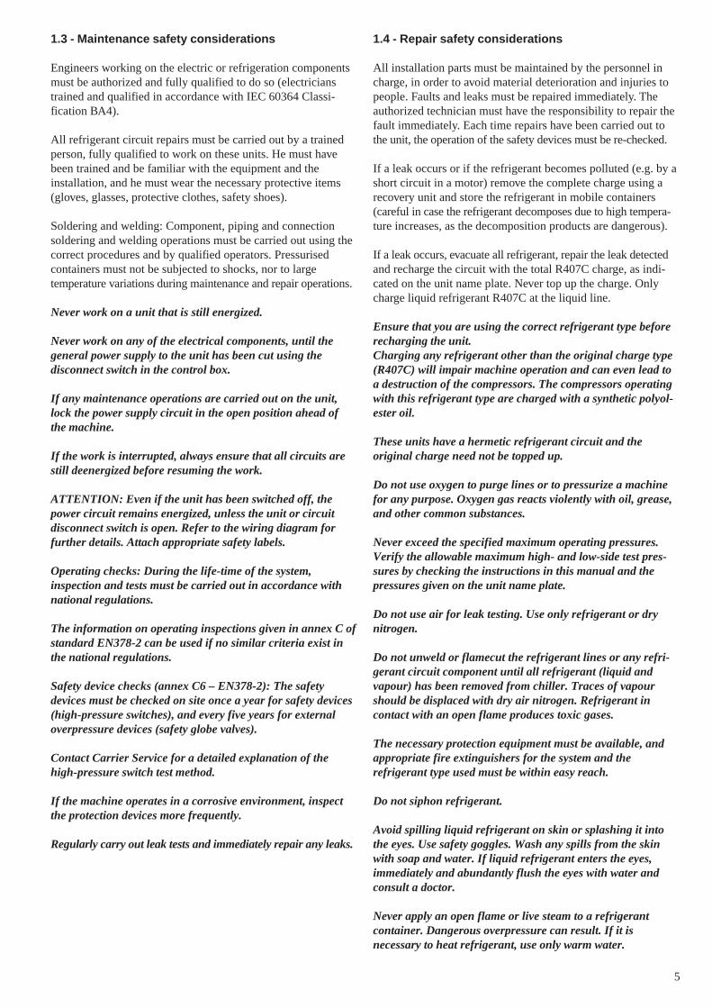
1.4 - Repair safety considerations
All installation parts must be maintained by the personnel incharge, in order to avoid material deterioration and injuries topeople. Faults and leaks must be repaired immediately. Theauthorized technician must have the responsibility to repair thefault immediately. Each time repairs have been carried out tothe unit, the operation of the safety devices must be re-checked.
If a leak occurs or if the refrigerant becomes polluted (e.g. by ashort circuit in a motor) remove the complete charge using arecovery unit and store the refrigerant in mobile containers(careful in case the refrigerant decomposes due to high tempera-ture increases, as the decomposition products are dangerous).
If a leak occurs, evacuate all refrigerant, repair the leak detectedand recharge the circuit with the total R407C charge, as indi-cated on the unit name plate. Never top up the charge. Onlycharge liquid refrigerant R407C at the liquid line.
Ensure that you are using the correct refrigerant type beforerecharging the unit.Charging any refrigerant other than the original charge type(R407C) will impair machine operation and can even lead toa destruction of the compressors. The compressors operatingwith this refrigerant type are charged with a synthetic polyol-ester oil.
These units have a hermetic refrigerant circuit and theoriginal charge need not be topped up.
Do not use oxygen to purge lines or to pressurize a machinefor any purpose. Oxygen gas reacts violently with oil, grease,and other common substances.
Never exceed the specified maximum operating pressures.Verify the allowable maximum high- and low-side test pres-sures by checking the instructions in this manual and thepressures given on the unit name plate.
Do not use air for leak testing. Use only refrigerant or drynitrogen.
Do not unweld or flamecut the refrigerant lines or any refri-gerant circuit component until all refrigerant (liquid andvapour) has been removed from chiller. Traces of vapourshould be displaced with dry air nitrogen. Refrigerant incontact with an open flame produces toxic gases.
The necessary protection equipment must be available, andappropriate fire extinguishers for the system and therefrigerant type used must be within easy reach.
Do not siphon refrigerant.
Avoid spilling liquid refrigerant on skin or splashing it intothe eyes. Use safety goggles. Wash any spills from the skinwith soap and water. If liquid refrigerant enters the eyes,immediately and abundantly flush the eyes with water andconsult a doctor.
Never apply an open flame or live steam to a refrigerantcontainer. Dangerous overpressure can result. If it isnecessary to heat refrigerant, use only warm water.
1.3 - Maintenance safety considerations
Engineers working on the electric or refrigeration componentsmust be authorized and fully qualified to do so (electricianstrained and qualified in accordance with IEC 60364 Classi-fication BA4).
All refrigerant circuit repairs must be carried out by a trainedperson, fully qualified to work on these units. He must havebeen trained and be familiar with the equipment and theinstallation, and he must wear the necessary protective items(gloves, glasses, protective clothes, safety shoes).
Soldering and welding: Component, piping and connectionsoldering and welding operations must be carried out using thecorrect procedures and by qualified operators. Pressurisedcontainers must not be subjected to shocks, nor to largetemperature variations during maintenance and repair operations.
Never work on a unit that is still energized.
Never work on any of the electrical components, until thegeneral power supply to the unit has been cut using thedisconnect switch in the control box.
If any maintenance operations are carried out on the unit,lock the power supply circuit in the open position ahead ofthe machine.
If the work is interrupted, always ensure that all circuits arestill deenergized before resuming the work.
ATTENTION: Even if the unit has been switched off, thepower circuit remains energized, unless the unit or circuitdisconnect switch is open. Refer to the wiring diagram forfurther details. Attach appropriate safety labels.
Operating checks: During the life-time of the system,inspection and tests must be carried out in accordance withnational regulations.
The information on operating inspections given in annex C ofstandard EN378-2 can be used if no similar criteria exist inthe national regulations.
Safety device checks (annex C6 – EN378-2): The safetydevices must be checked on site once a year for safety devices(high-pressure switches), and every five years for externaloverpressure devices (safety globe valves).
Contact Carrier Service for a detailed explanation of thehigh-pressure switch test method.
If the machine operates in a corrosive environment, inspectthe protection devices more frequently.
Regularly carry out leak tests and immediately repair any leaks.

6
During refrigerant removal and storage operations followapplicable regulations. These regulations, permitting condition-ing and recovery of halogenated hydrocarbons under opti-mum quality conditions for the products and optimum safetyconditions for people, property and the environment aredescribed in standard NFE 29795.
Any refrigerant transfer and recovery operations must becarried out using a transfer unit. A 3/8” SAE connector onthe manual liquid line valve is supplied with all units forconnection to the transfer station. The units must never bemodified to add refrigerant and oil charging, removal andpurging devices. All these devices are provided with the units.Please refer to the certified dimensional drawings for the units.
Do not re-use disposable (non-returnable) cylinders orattempt to refill them. It is dangerous and illegal. Whencylinders are empty, evacuate the remaining gas pressure,and move the cylinders to a place designated for theirrecovery. Do not incinerate.
Do not attempt to remove refrigerant circuit components orfittings, while the machine is under pressure or while it isrunning. Be sure pressure is at 0 kPa before removingcomponents or opening a circuit.
Any manipulation (opening or closing) of a shut-off valvemust be carried out by a qualified and authorised engineer.These procedures must be carried out with the unit shut-down.
NOTE: The unit must never be left shut down with the liquidline valve closed, as liquid refrigerant can be trapped betweenthis valve and the expansion device. (This valve is situated onthe liquid line before the filter drier box.)
Do not attempt to repair or recondition any safety deviceswhen corrosion or build-up of foreign material (rust, dirt,scale, etc.) is found within the valve body or mechanism. Ifnecessary, replace the device. Do not install safety valves inseries or backwards.
CAUTIONDo not step on refrigerant lines. The lines can break underthe weight and release refrigerant, causing personal injury.
No part of the unit must use feet, racks or supports duringoperation. Periodically monitor and repair or if necessaryreplace any component or piping that shows signs of damage.
Do not climb on a machine. Use a platform, or staging towork at higher levels.
Use mechanical lifting equipment (crane, hoist, etc.) to lift ormove heavy components such as compressors or plate heatexchangers. For lighter components, use lifting equipmentwhen there is a risk of slipping or losing your balance.
Use only original replacement parts for any repair or compo-nent replacement. Consult the list of replacement parts thatcorresponds to the specification of the original equipment.
Do not drain water circuits containing industrial brines,without informing the technical service department at theinstallation site or a competent body first.
Close the entering and leaving water shutoff valves andpurge the unit hydronic circuit, before working on thecomponents installed on the circuit (screen filter, pump, waterflow switch, etc.).
Periodically inspect all valves, fittings and pipes of therefrigerant and hydronic circuits to ensure that they do notshow any corrosion or any signs of leaks.

7
2.2 - Moving and siting the unit
2.2.1 - Moving
See chapter "Installation safety considerations"
2.2.2 - Siting the unit
Always refer to the chapter "Dimensions and clearances" toconfirm that there is adequate space for all connections andservice operations. For the centre of gravity coordinates, theposition of the unit mounting holes, and the weight distribu-tion points, refer to the certified dimensional drawing suppliedwith the unit.
CAUTION: Only use slings at the designated lifting pointswhich are marked on the unit.
Before siting the unit check that:• the permitted loading at the site is adequate or that
appropriate strenghtening measures have been taken.• the surface is horizontal, flat and intact.• there is adequate space above the unit for air flow.• there are adequate support points and that they are in the
right places.• the location is not subject to flooding.• where heavy snowfall is likely and long periods of sub-
zero temperatures are normal, provision has been made toprevent snow accumulating by raising the unit above theheight of drifts normally experienced.
Baffles may be necessary to deflect strong winds and toprevent snow from blowing directly into the unit. Theymust not restrict air flow into the unit.
CAUTION: Before lifting the unit, check that all casingpanels are securely fixed in place. Lift and set down the unitwith great care. Tilting and jarring can damage the unit andimpair unit operation.
The 30RA units can be hoisted with rigging. Coils shouldalways be protected against crushing while a unit is beingmoved. Use struts or spreader bars to spread the slings abovethe unit. Do not tilt a unit more than 15°.
WARNING: Never push or lever on any of the enclosurepanels of the unit. Only the base of the unit frame is designedto withstand such stresses.
2 - PRELIMINARY CHECKS
2.1 - Check equipment received
• Inspect the unit for damage or missing parts. If damage isdetected, or if shipment is incomplete, immediately file aclaim with the shipping company.
• Confirm that the unit received is the one ordered.Compare the name plate data with the order.
• The unit name plate must include the followinginformation:- Version number- Model number- CE marking- Serial number- Year of manufacture and test date- Refrigerant used and refrigerant class- Refrigerant charge per circuit- Containment fluid to be used- PS: Min./max. allowable pressure (high and low
pressure side)- TS: Min./max. allowable temperature (high and low
pressure side)- Globe valve cut-out pressure- Pressure switch cut-out pressure- Unit leak test pressure- Voltage, frequency, number of phases- Maximum current drawn- Maximum power input- Unit net weight
High pressure Low pressureMin. Max. Min. Max.
PS (bar) -0.9 32 -0.9 25TS (°C) -20 72 -20 62Pressure switch cut-out pressure (bar) 29 -Valve cut-out pressure (bar) - 25Test pressure, unit leak test (bar) 15
• Confirm that all accessories ordered for on-site installationhave been delivered, and are complete and undamaged.
• The unit must be checked periodically during its wholeoperating life to ensure that no shocks (handlingaccessories, tools etc.) have damaged it. If necessary, thedamaged parts must be repaired or replaced. See alsochapter “Maintenance”.
8
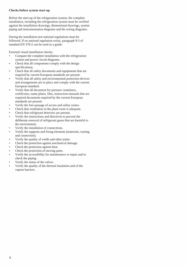
Checks before system start-up
Before the start-up of the refrigeration system, the completeinstallation, including the refrigeration system must be verifiedagainst the installation drawings, dimensional drawings, systempiping and instrumentation diagrams and the wiring diagrams.
During the installation test national regulations must befollowed. If no national regulation exists, paragraph 9-5 ofstandard EN 378-2 can be used as a guide.
External visual installation checks:• Compare the complete installation with the refrigeration
system and power circuit diagrams.• Check that all components comply with the design
specifications.• Check that all safety documents and equipments that are
required by current European standards are present.• Verify that all safety and environmental protection devices
and arrangements are in place and comply with the currentEuropean standard.
• Verify that all document for pressure containers,certificates, name plates, files, instruction manuals that arerequired documents required by the current Europeanstandards are present.
• Verify the free passage of access and safety routes.• Check that ventilation in the plant room is adequate.• Check that refrigerant detectors are present.• Verify the instructions and directives to prevent the
deliberate removal of refrigerant gases that are harmful tothe environment.
• Verify the installation of connections.• Verify the supports and fixing elements (materials, routing
and connection).• Verify the quality of welds and other joints.• Check the protection against mechanical damage.• Check the protection against heat.• Check the protection of moving parts.• Verify the accessibility for maintenance or repair and to
check the piping.• Verify the status of the valves.• Verify the quality of the thermal insulation and of the
vapour barriers.
9
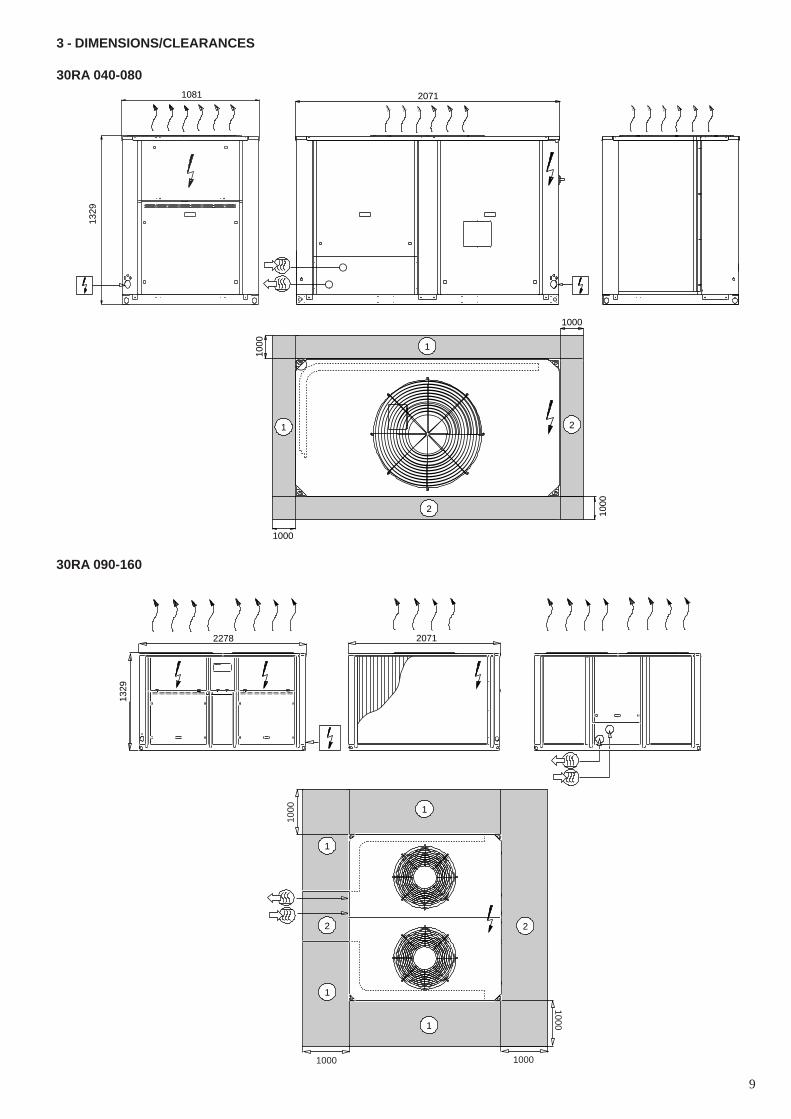
30RA 090-160
3 - DIMENSIONS/CLEARANCES
30RA 040-080
1000
1000
1000
1000
1081 207113
29
1
1
2
2
1000
1000
1000
1000
1329
20712278
2
1
1
1
1
2

10
Multiple chiller installationNOTE: If the walls are higher than 2 m, contact the factory.
2000
1000
2000
1000
2000
2000
1000
10001000
Solid surface Solid surface
30RA 200-240
2
1
1
1
1
2
1000
100010
00
1000
2
2
2279 3351
1674
Legend:All dimensions are given in mm
Power supply
Water inlet
Water outlet
Required clearances for air flow
Recommended clearances for maintenance
Air outlet, do not obstruct
Power cable entry
NOTE:
A Non-certified drawings.Refer to the certified dimensional drawings supplied with the unit oravailable on request, when designing an installation.
For the location of fixing points, weight distribution and coordinates ofthe centre of gravity refer to the certified dimensional drawings.
B In multiple-chiller installations (maximum four units), the side clearancebetween the units should be increased from 1000 to 2000 mm.
C The height of the solid surface must not exceed 2 m.

11
4 - PHYSICAL DATA
30RA 040 050 060 070 080 090 100 120 140 160 200 240
Net nominal cooling capacity, single pump* kW 39.3 49.5 58 68 79 90 98 116 136 158 206 248Net nominal cooling capacity, dual pump* kW 38.1 48.5 57 67 79 89 97 114 135 158 206 248
Operating weight kgwith hydronic module, single pump 526 584 597 611 631 1093 1106 1205 1212 1248 2133 2305with hydronic module, dual pump 606 664 677 691 708 1170 1183 1305 1312 1348 2221 2393Operating weight without hydronic module kg 502 560 573 587 605 1062 1075 1167 1174 1210 1986 2158
Refrigerant charge R-407CCircuit A kg 10 13 15 12.5 18 10 10 15 12.5 18 21 28Circuit B kg - - - - - 13 14 15 12.5 18 28 28
Compressors Hermetic, scroll 48.3 r/sQuantity, circuit A 1 2 2 2 2 1 1 2 2 2 2 3Quantity, circuit B - - - - - 2 2 2 2 2 3 3Number of capacity steps 1 2 2 2 2 3 3 4 4 4 5 6Minimum capacity % 100 46 42 50 50 25 25 21 25 25 20 16.6
Control type PRO-DIALOG Plus
Condensers Grooved copper tubes and aluminium fins
Fans Axial FLYING-BIRD fans, with rotating shroudQuantity 1 1 1 1 1 2 2 2 2 2 4 4Air flow (high speed) l/s 3945 3780 4220 5150 5800 7725 8165 9745 10300 11600 17343 20908Speed (high/low) r/s 11.5/5.8 11.5/5.8 11.5/5.8 15.6/7.8 15.6/7.8 11.5/5.8 11.5/5.8 15.6/7.8 15.6/7.8 15.6/7.8 11.5/5.8 15.6/7.8
Evaporator Welded, direct-expansion plate heat exchangerWater volume l 3.6 4.6 5.9 6.5 7.6 8.2 9.5 11.2 13 15.2 22 26Max. water-side operating pressure kPawithout hydronic module 1000 1000 1000 1000 1000 1000 1000 1000 1000 1000 1000 1000with hydronic module 300 300 300 300 300 300 300 300 300 300 400 400
Hydronic module Pump, safety valve, expansion tank, flow switch and flow control valve.Victaulic screen filter, pressure gauge, purge valves (water and air) Screen filter, two
pressure gauges,purge valve
Pump, single centrifugal Composite monocell pump, 48.3 r/s Monocell pump, 48.3 r/sQuantity 1 1 1 1 1 1 1 1 1 1 1 1Expansion tank volume l 12 12 12 12 12 35 35 35 35 35 50 50
Water connection type Victaulic (sleeves for welded or screw connection supplied) Threaded male(with or without hydronic module) conical gas connectionDiameter in 2 2 2 2 2 2 2 2-1/2 2-1/2 2-1/2 3 3Outside tube diameter mm 60.3 60.3 60.3 60.3 60.3 60.3 60.3 76.1 76.1 76.1 88.9 88.9
* Standard EUROVENT conditions: evaporator entering/leaving water = 12°C/7°C, outdoor air temperature = 35°CNet nominal cooling capacity based on Eurovent conditions = gross cooling capacity plus the capacity corresponding to the available pressure (flow x pressure/0.3)
5 - ELECTRICAL DATA
30RA 040 050 060 070 080 090 100 120 140 160 200 240
Power circuitNominal voltage V-ph-Hz 400-3-50Voltage range V 360-440
Control circuit supply The control circuit is supplied via the transformer installed on the unit
Maximum unit power input* kW 20.3 24.6 28.9 33.9 40 44.1 48.4 58.1 68.1 79.7 104.3 124.9Nominal unit current draw** A 30 35.6 42.2 51 57.2 64.5 71.1 85.2 102.9 113.2 151 179.1Maximum unit current draw*** A 35 42.6 49.3 58.2 67.2 76.5 83.2 99.4 117.2 133.2 176.3 209.1Maximum start-up current**** AStandard unit† 181 153 159 168 213 222 229 209 227 279 322 355Unit with electronic starter (option)‡ 119 107 112 120 152 - - - - - - -
Three-phase short-circuit holding current kA 10 10 10 10 10 10 10 10 10 10 10 10
* Power input, compressor(s) + fan(s) + pump, at max. unit operating conditions (water entering/leaving temperature = 15°C/10°C and a maximum air enteringtemperature of 45°C ± 1 K depending on the unit size and at a nominal voltage of 400 V) (values given on the unit name plate).
** Nominal unit operating current draw at standard Eurovent conditions: evaporator entering/leaving water = 12°C/7°C, outdoor air temperature = 35°C. The currentvalues are given for a nominal voltage of 400 V.
*** Maximum unit operating current at maximum unit power input and 400 V (data shown on the unit name plate).**** Maximum instantaneous start-up current (max. operating current of the smallest compressor(s) + fan current + pump current + locked rotor current of the largest
compressor).† Maximum instantaneous starting current at 400 V nominal voltage (maximum operating current of the smallest compressors + fan current + pump current + locked
rotor current of the largest compressor).‡ Maximum instantaneous starting current at 400 V nominal voltage and with compressor with electronic starter (maximum operating current of the smallest
compressor(s) + fan current + pump current + reduced start-up current of the largest compressor).
12
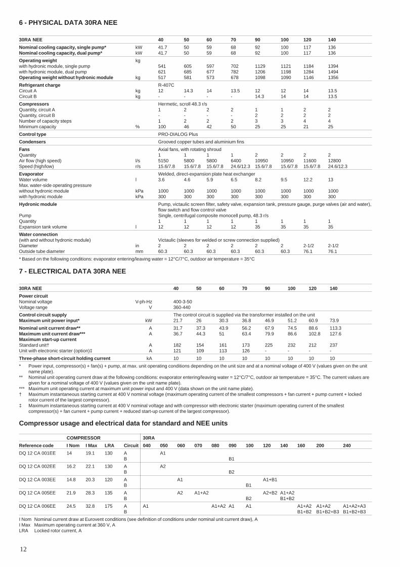
6 - PHYSICAL DATA 30RA NEE
30RA NEE 40 50 60 70 90 100 120 140
Nominal cooling capacity, single pump* kW 41.7 50 59 68 92 100 117 136Nominal cooling capacity, dual pump* kW 41.7 50 59 68 92 100 117 136
Operating weight kgwith hydronic module, single pump 541 605 597 702 1129 1121 1184 1394with hydronic module, dual pump 621 685 677 782 1206 1198 1284 1494Operating weight without hydronic module kg 517 581 573 678 1098 1090 1146 1356
Refrigerant charge R-407CCircuit A kg 12 14.3 14 13.5 12 12 14 13.5Circuit B kg - - - - 14.3 14 14 13.5
Compressors Hermetic, scroll 48.3 r/sQuantity, circuit A 1 2 2 2 1 1 2 2Quantity, circuit B - - - - 2 2 2 2Number of capacity steps 1 2 2 2 3 3 4 4Minimum capacity % 100 46 42 50 25 25 21 25
Control type PRO-DIALOG Plus
Condensers Grooved copper tubes and aluminium fins
Fans Axial fans, with rotating shroudQuantity 1 1 1 1 2 2 2 2Air flow (high speed) l/s 5150 5800 5800 6400 10950 10950 11600 12800Speed (high/low) r/s 15.6/7.8 15.6/7.8 15.6/7.8 24.6/12.3 15.6/7.8 15.6/7.8 15.6/7.8 24.6/12.3
Evaporator Welded, direct-expansion plate heat exchangerWater volume l 3.6 4.6 5.9 6.5 8.2 9.5 12.2 13Max. water-side operating pressurewithout hydronic module kPa 1000 1000 1000 1000 1000 1000 1000 1000with hydronic module kPa 300 300 300 300 300 300 300 300
Hydronic module Pump, victaulic screen filter, safety valve, expansion tank, pressure gauge, purge valves (air and water),flow switch and flow control valve
Pump Single, centrifugal composite monocell pump, 48.3 r/sQuantity 1 1 1 1 1 1 1 1Expansion tank volume l 12 12 12 12 35 35 35 35
Water connection(with and without hydronic module) Victaulic (sleeves for welded or screw connection supplied)Diameter in 2 2 2 2 2 2 2-1/2 2-1/2Outside tube diameter mm 60.3 60.3 60.3 60.3 60.3 60.3 76.1 76.1
* Based on the following conditions: evaporator entering/leaving water = 12°C/7°C, outdoor air temperature = 35°C
7 - ELECTRICAL DATA 30RA NEE
30RA NEE 40 50 60 70 90 100 120 140
Power circuitNominal voltage V-ph-Hz 400-3-50Voltage range V 360-440
Control circuit supply The control circuit is supplied via the transformer installed on the unitMaximum unit power input* kW 21.7 26 30.3 36.8 46.9 51.2 60.9 73.9
Nominal unit current draw** A 31.7 37.3 43.9 56.2 67.9 74.5 88.6 113.3Maximum unit current draw*** A 36.7 44.3 51 63.4 79.9 86.6 102.8 127.6Maximum start-up currentStandard unit† A 182 154 161 173 225 232 212 237Unit with electronic starter (option)‡ A 121 109 113 126 - - - -
Three-phase short-circuit holding current kA 10 10 10 10 10 10 10 10
* Power input, compressor(s) + fan(s) + pump, at max. unit operating conditions depending on the unit size and at a nominal voltage of 400 V (values given on the unitname plate).
** Nominal unit operating current draw at the following conditions: evaporator entering/leaving water = 12°C/7°C, outdoor air temperature = 35°C. The current values aregiven for a nominal voltage of 400 V (values given on the unit name plate).
*** Maximum unit operating current at maximum unit power input and 400 V (data shown on the unit name plate).† Maximum instantaneous starting current at 400 V nominal voltage (maximum operating current of the smallest compressors + fan current + pump current + locked
rotor current of the largest compressor).‡ Maximum instantaneous starting current at 400 V nominal voltage and with compressor with electronic starter (maximum operating current of the smallest
compressor(s) + fan current + pump current + reduced start-up current of the largest compressor).
Compressor usage and electrical data for standard and NEE units
COMPRESSOR 30RA
Reference code I Nom I Max LRA Circuit 040 050 060 070 080 090 100 120 140 160 200 240
DQ 12 CA 001EE 14 19.1 130 A A1B B1
DQ 12 CA 002EE 16.2 22.1 130 A A2B B2
DQ 12 CA 003EE 14.8 20.3 120 A A1 A1+B1B B1
DQ 12 CA 005EE 21.9 28.3 135 A A2 A1+A2 A2+B2 A1+A2B B2 B1+B2
DQ 12 CA 006EE 24.5 32.8 175 A A1 A1+A2 A1 A1 A1+A2 A1+A2 A1+A2+A3B B1+B2 B1+B2+B3 B1+B2+B3
I Nom Nominal current draw at Eurovent conditions (see definition of conditions under nominal unit current draw), AI Max Maximum operating current at 360 V, ALRA Locked rotor current, A

13
- outdoor installation*- ambient temperature range: -10°C to +46°C, class 4K3*- altitude: ≤ 2000 m- presence of hard solids, class 4S2 (no significant dust present)- presence of corrosive and polluting substances, class 4C2 (negligible)- vibration and shock, class 4M2
b. Competence of personnel, class BA4* (trained personnel - IEC 60364)2. Power supply frequency variation: ± 2 Hz.3. The neutral (N) conductor must not be connected directly to the unit (if
necessary use a transformer).4. Overcurrent protection of the power supply conductors is not provided with the
unit.5. The factory-installed disconnect switch(es)/circuit breaker(s) is (are) of a type
suitable for power interruption in accordance with EN 60947.6. The units are designed for connection to TN networks (IEC 60364). For IT
networks the earth connection must not be at the network earth. Provide alocal earth, consult competent local organisations to complete the electricalinstallation.
Caution: If particular aspects of an actual installation do not conform to theconditions described above, or if there are other conditions which should beconsidered, always contact your local Carrier representative.
* The required protection level for this class is IP43BW (according to referencedocument IEC 60529). All 30RA units are protected to IP44CW and fulfil thisprotection condition.
Electrical data notes 30RA:
• 30RA 040-240 units have a single power connection point located at the mainswitch.
• The control box includes the following standard features:- a main disconnect switch, starter and motor protection devices for each
compressor, the fan and the pump- the control devices
• Field connections:All connections to the system and the electrical installations must be in fullaccordance with all applicable local codes.
• The Carrier 30RA units are designed and built to ensure conformance withthese codes. The recommendations of European standard EN 60204-1(machine safety - electrical machine components - part 1: general regulations -corresponds to IEC 60204-1) are specifically taken into account, whendesigning the electrical equipment.
NOTES:• Generally the recommendations of IEC 60364 are accepted as compliance
with the requirements of the installation directives. Conformance with EN60204 is the best means of ensuring compliance with the Machines Directive §1.5.1.
• Annex B of EN 60204-1 describes the electrical characteristics used for theoperation of the machines.
1. The operating environment for the 30RA units is specified below:a. Environment* - Environment as classified in EN 60721 (corresponds to
IEC 60721):
Electrical data notes 30RA NEE units:
• 30RA 040-140 NEE units have a single power connection point located at themain switch.
• The control box includes the following standard features:- a main disconnect switch, starter and motor protection devices for each
compressor, the fan and the pump- the control devices
• Field connections:All connections to the system and the electrical installations must be in fullaccordance with all applicable local codes.
• The Carrier 30RA NEE units are designed and built to ensure conformancewith these codes. The recommendations of standard IEC 60204-1 (machinesafety - electrical machine components - part 1: general regulations) arespecifically taken into account, when designing the electrical equipment.
NOTES:• The recommendations of IEC 60364 (standards issued by the International
Electrotechnical Commission) are accepted as compliance with therequirements of the installation directives.
• Annex B of EN 60204-1 describes the electrical characteristics used for theoperation of the machines.
1. The environment conditions for these units are specified below:- outdoor installation(1)
- ambient temperature range: -10°C to +50°C ± 1 K depending on the unit- altitude: ≤ 2000 m- presence of hard solids: significant dust present*- presence of corrosive and polluting substances: negligible**- vibration and shock: negligible- Minimum competence level of personnel: instructed personnel***
(1) The required protection level for this class is IP43BW†. All 30RA units areprotected to IP44CW† (electrical compartment protected against intrusion ofhard solids or liquid splashes), and fulfil this protection condition.
2. Power supply frequency variation: ± 2 Hz.3. The neutral (N) conductor must not be connected directly to the unit (if
necessary use a transformer).4. Overcurrent protection of the power supply conductors is not provided with the
unit.5. The factory-installed disconnect switch(es)/circuit breaker(s) is (are) of a type
suitable for power interruption in accordance with EN 60947‡.6. The units are designed for connection to TN networks (IEC 60364). For IT
networks the earth connection must not be at the network earth. Provide alocal earth, consult competent local organisations to complete the electricalinstallation.
Caution: If particular aspects of an actual installation do not conform to theconditions described above, or if there are other conditions which should beconsidered, always contact your local Carrier representative.
Notes:* During operation the maintenance programme must take into account the dust
in the environment.** In case of condensation in the control box, ensure tropicalisation of the control
boxes.*** Trained personnel: Personnel trained by a specialist, to ensure that he/she
avoids any possible danger and risk in using electricity (IEC 60364 BA4 –classification of competence of personnel)
† Corresponds to IEC 60529 (IP codes correspond to the protection degree ofthe unit enclosure).
‡ IEC 60947-3 (low-capacity control and regulation units – Part 3: for a unit,associated disconnect switches, circuit breakers, disconnect buttons andfuses).
14
8 - APPLICATION DATA
8.1 - Unit operating range
8.1.1 - 30RA unitsEvaporator Minimum °C Maximum °C
Water entering temp. (at start-up) 7.8 * 30Water leaving temp. (in operation) 5 ** 15Water entering temp. (at shut down) - 55
Condenser
Entering air temp. -10*** 46***
8.1.2 - 30RA NEE unitsEvaporator Minimum °C Maximum °C
Water entering temp. (at start-up) 7.8 * 40Water leaving temp. (in operation) 5 ** 15Water entering temp. (at shut down) - 55
Condenser
Entering air temp. -10*** 50***
Do not exceed the maximum operating temperature.* For a system requiring operation below 7,8°C, contact Carrier SA.** For a system requiring operation below 5°C, anti-freeze must be added to the
unit.*** Maximum outside temperature: For transport and storage of the 30RA units
the minimum and maximum allowable temperatures are –20°C and +55°C. Itis recommended that these temperatures are used for transport by container.
8.2 - Evaporator water flow rates
30RA Evaporator water flow
Min. flow rate Max. flow rate* Max. flow rate**Single pump Dual pump
l/s l/s l/s l/s
040 1.1 3.5 4.4 3.7050 1.1 4 5.2 4.6060 1.4 4.4 6 5.8070 1.5 4.6 6.4 6.4080 1.7 5.5 6.8 7.3090 2.7 5.6 6.9 7.6100 3 5.8 7.4 8.8120 3.6 8.5 10.5 10.8140 4.2 8.8 11.4 12.7160 4.8 9.1 11.9 14.4200 5.6 15.3 15.3 19.1240 6.8 23.4 23.4 24.2
30RA NEE Evaporator water flow
Min. flow rate Max. flow rate* Max. flow rate**Single pump Dual pump
l/s l/s l/s l/s
040 1.1 3.5 4.4 3.7050 1.1 4 5.2 4.6060 1.4 4.4 6 5.8070 1.5 4.6 6.4 6.4090 2.7 5.6 6.9 7.6100 3 5.8 7.4 8.8120 3.6 8.5 10.5 10.8140 4.2 8.8 11.4 12.7
Legend* Maximum flow rate at an available pressure of 50 kPa (unit with hydronic
module).** Maximum flow rate at a pressure drop of 100 kPa in the plate heat exchanger
(unit without hydronic module).
8.3 - Minimum water flow rate
If the installation flow rate is below the minimum flow rate,recirculation of the evaporator water flow may take place,leading to the risk of excessive fouling.
8.4 - Maximum evaporator water flow rate
This is limited by the permitted evaporator pressure drop.Also, a minimum evaporator ∆T of 2.8 K must be guaranteed,which corresponds to a water flow rate of 0.9 l/s per kW.
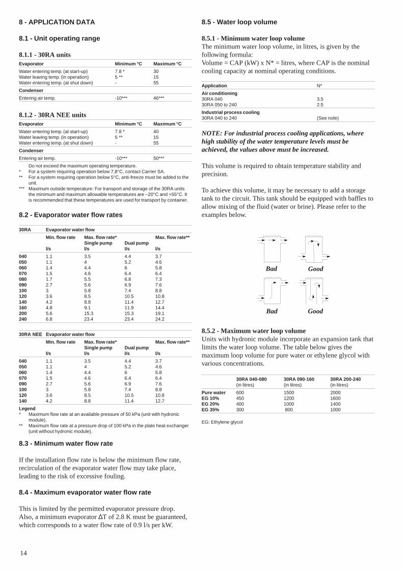
8.5 - Water loop volume
8.5.1 - Minimum water loop volumeThe minimum water loop volume, in litres, is given by thefollowing formula:Volume = CAP (kW) x N* = litres, where CAP is the nominalcooling capacity at nominal operating conditions.
Application N*
Air conditioning30RA 040 3.530RA 050 to 240 2.5
Industrial process cooling30RA 040 to 240 (See note)
NOTE: For industrial process cooling applications, wherehigh stability of the water temperature levels must beachieved, the values above must be increased.
This volume is required to obtain temperature stability andprecision.
To achieve this volume, it may be necessary to add a storagetank to the circuit. This tank should be equipped with baffles toallow mixing of the fluid (water or brine). Please refer to theexamples below.
8.5.2 - Maximum water loop volumeUnits with hydronic module incorporate an expansion tank thatlimits the water loop volume. The table below gives themaximum loop volume for pure water or ethylene glycol withvarious concentrations.
30RA 040-080 30RA 090-160 30RA 200-240(in litres) (in litres) (in litres)
Pure water 600 1500 2000EG 10% 450 1200 1600EG 20% 400 1000 1400EG 35% 300 800 1000
EG: Ethylene glycol
Bad Good
Bad Good
15
1
10
100
1000
10000
1 10 403020
1 2
34
5
6
7
8
9
1011
12
45
46
-10
˚C
0 5 10 ˚C
4444.5
8
Evaporator water leaving temperature
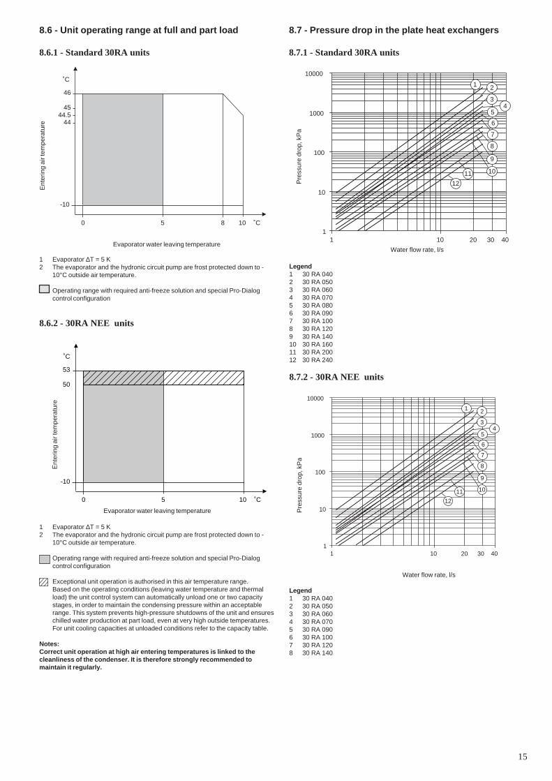
1 Evaporator ∆T = 5 K2 The evaporator and the hydronic circuit pump are frost protected down to -
10°C outside air temperature.
Operating range with required anti-freeze solution and special Pro-Dialogcontrol configuration
8.6.2 - 30RA NEE units
8.6 - Unit operating range at full and part load
8.6.1 - Standard 30RA units
50
53
-10
˚C
0 5 10 ˚C
Evaporator water leaving temperature
Ent
erin
g ai
r tem
pera
ture
1 Evaporator ∆T = 5 K2 The evaporator and the hydronic circuit pump are frost protected down to -
10°C outside air temperature.
Operating range with required anti-freeze solution and special Pro-Dialogcontrol configuration
Exceptional unit operation is authorised in this air temperature range.Based on the operating conditions (leaving water temperature and thermalload) the unit control system can automatically unload one or two capacitystages, in order to maintain the condensing pressure within an acceptablerange. This system prevents high-pressure shutdowns of the unit and ensureschilled water production at part load, even at very high outside temperatures.For unit cooling capacities at unloaded conditions refer to the capacity table.
Notes:Correct unit operation at high air entering temperatures is linked to thecleanliness of the condenser. It is therefore strongly recommended tomaintain it regularly.
8.7 - Pressure drop in the plate heat exchangers
8.7.1 - Standard 30RA units
Pre
ssur
e dr
op, k
Pa
Legend1 30 RA 0402 30 RA 0503 30 RA 0604 30 RA 0705 30 RA 0806 30 RA 0907 30 RA 1008 30 RA 1209 30 RA 14010 30 RA 16011 30 RA 20012 30 RA 240
8.7.2 - 30RA NEE units
Pre
ssur
e dr
op, k
Pa
Water flow rate, l/s
Legend1 30 RA 0402 30 RA 0503 30 RA 0604 30 RA 0705 30 RA 0906 30 RA 1007 30 RA 1208 30 RA 140
Ent
erin
g ai
r tem
pera
ture
Water flow rate, l/s
1
10
100
1000
10000
1 10 403020
1 2
34
5
6
7
8
9
1011
12
16
9 - ELECTRICAL CONNECTION
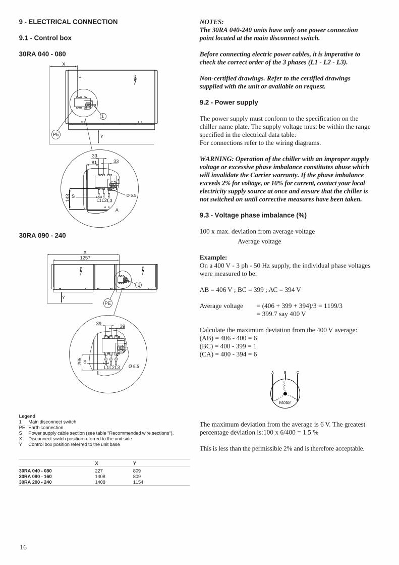
9.1 - Control box
30RA 040 - 080
30RA 090 - 240
NOTES:The 30RA 040-240 units have only one power connectionpoint located at the main disconnect switch.
Before connecting electric power cables, it is imperative tocheck the correct order of the 3 phases (L1 - L2 - L3).
Non-certified drawings. Refer to the certified drawingssupplied with the unit or available on request.
9.2 - Power supply
The power supply must conform to the specification on thechiller name plate. The supply voltage must be within the rangespecified in the electrical data table.For connections refer to the wiring diagrams.
WARNING: Operation of the chiller with an improper supplyvoltage or excessive phase imbalance constitutes abuse whichwill invalidate the Carrier warranty. If the phase imbalanceexceeds 2% for voltage, or 10% for current, contact your localelectricity supply source at once and ensure that the chiller isnot switched on until corrective measures have been taken.
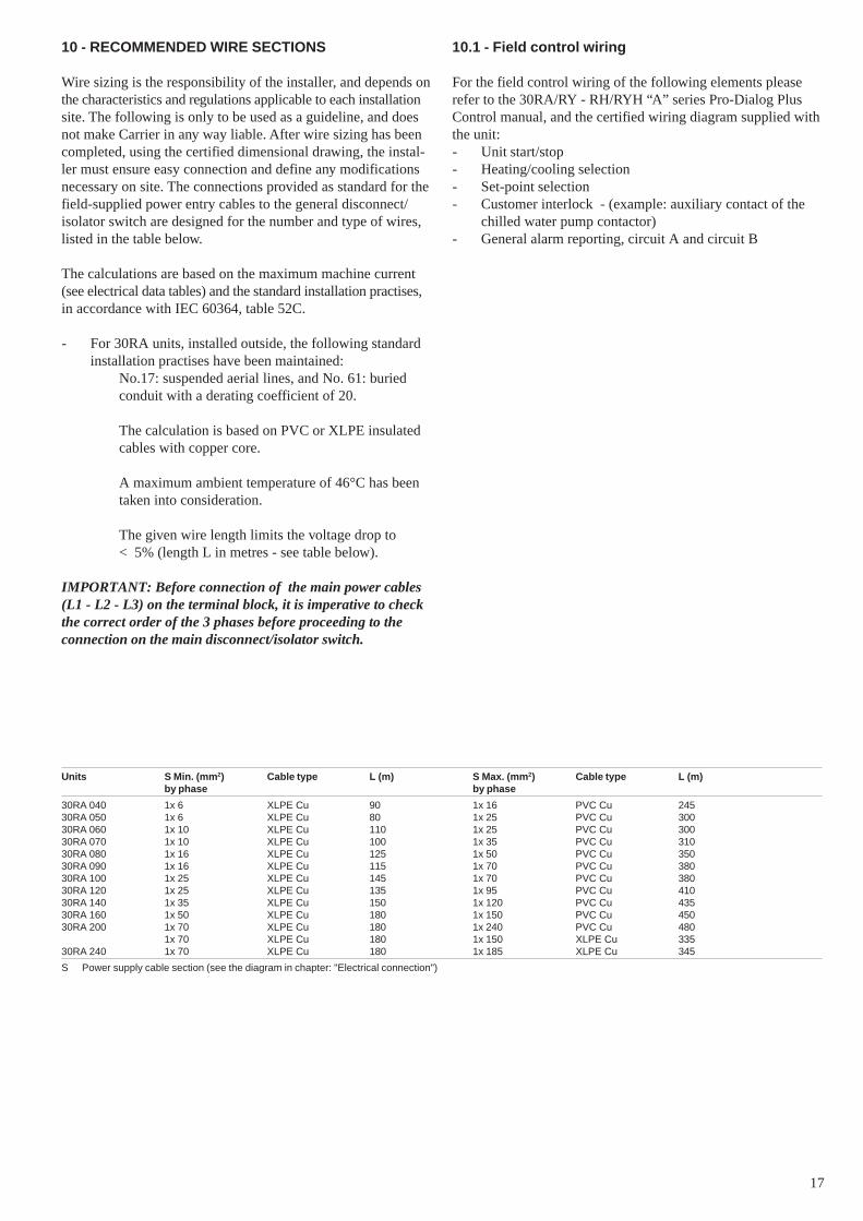
9.3 - Voltage phase imbalance (%)
100 x max. deviation from average voltage
Average voltage
Example:On a 400 V - 3 ph - 50 Hz supply, the individual phase voltageswere measured to be:
AB = 406 V ; BC = 399 ; AC = 394 V
Average voltage = (406 + 399 + 394)/3 = 1199/3= 399.7 say 400 V
Calculate the maximum deviation from the 400 V average:(AB) = 406 - 400 = 6(BC) = 400 - 399 = 1(CA) = 400 - 394 = 6
The maximum deviation from the average is 6 V. The greatestpercentage deviation is:100 x 6/400 = 1.5 %
This is less than the permissible 2% and is therefore acceptable.
Legend1 Main disconnect switchPE Earth connectionS Power supply cable section (see table "Recommended wire sections").X Disconnect switch position referred to the unit sideY Control box position referred to the unit base
X Y
30RA 040 - 080 227 80930RA 090 - 160 1408 80930RA 200 - 240 1408 1154
A
1
PE
S
3333
81
L1L2L3143
X
Y
1257
1
PE
X
Y
S
39 39
295
L1L2L3
Motor
17
10 - RECOMMENDED WIRE SECTIONS
Wire sizing is the responsibility of the installer, and depends onthe characteristics and regulations applicable to each installationsite. The following is only to be used as a guideline, and doesnot make Carrier in any way liable. After wire sizing has beencompleted, using the certified dimensional drawing, the instal-ler must ensure easy connection and define any modificationsnecessary on site. The connections provided as standard for thefield-supplied power entry cables to the general disconnect/isolator switch are designed for the number and type of wires,listed in the table below.
The calculations are based on the maximum machine current(see electrical data tables) and the standard installation practises,in accordance with IEC 60364, table 52C.
- For 30RA units, installed outside, the following standardinstallation practises have been maintained:
No.17: suspended aerial lines, and No. 61: buriedconduit with a derating coefficient of 20.
The calculation is based on PVC or XLPE insulatedcables with copper core.
A maximum ambient temperature of 46°C has beentaken into consideration.
The given wire length limits the voltage drop to< 5% (length L in metres - see table below).
IMPORTANT: Before connection of the main power cables(L1 - L2 - L3) on the terminal block, it is imperative to checkthe correct order of the 3 phases before proceeding to theconnection on the main disconnect/isolator switch.
Units S Min. (mm2) Cable type L (m) S Max. (mm2) Cable type L (m)by phase by phase
30RA 040 1x 6 XLPE Cu 90 1x 16 PVC Cu 24530RA 050 1x 6 XLPE Cu 80 1x 25 PVC Cu 30030RA 060 1x 10 XLPE Cu 110 1x 25 PVC Cu 30030RA 070 1x 10 XLPE Cu 100 1x 35 PVC Cu 31030RA 080 1x 16 XLPE Cu 125 1x 50 PVC Cu 35030RA 090 1x 16 XLPE Cu 115 1x 70 PVC Cu 38030RA 100 1x 25 XLPE Cu 145 1x 70 PVC Cu 38030RA 120 1x 25 XLPE Cu 135 1x 95 PVC Cu 41030RA 140 1x 35 XLPE Cu 150 1x 120 PVC Cu 43530RA 160 1x 50 XLPE Cu 180 1x 150 PVC Cu 45030RA 200 1x 70 XLPE Cu 180 1x 240 PVC Cu 480
1x 70 XLPE Cu 180 1x 150 XLPE Cu 33530RA 240 1x 70 XLPE Cu 180 1x 185 XLPE Cu 345
S Power supply cable section (see the diagram in chapter: "Electrical connection")
10.1 - Field control wiring
For the field control wiring of the following elements pleaserefer to the 30RA/RY - RH/RYH “A” series Pro-Dialog PlusControl manual, and the certified wiring diagram supplied withthe unit:- Unit start/stop- Heating/cooling selection- Set-point selection- Customer interlock - (example: auxiliary contact of the
chilled water pump contactor)- General alarm reporting, circuit A and circuit B

18
11 - WATER CONNECTIONS
For size and position of the unit water inlet and outlet connec-tions refer to the certified dimensional drawings supplied withthe unit. The water pipes must not transmit any radial or axialforce to the heat exchangers nor any vibration.
The water supply must be analysed and appropriate filtering,treatment, control devices, shutoff and bleed valves and circuitsbuilt in, to prevent corrosion (example: damage to the protectionof the tube surface if the fluid is polluted), fouling and deter-ioration of the pump fittings.
Before any start-up verify that the heat exchange fluid iscompatible with the materials and the water circuit coating.
In case additives or other fluids than those recommended byCarrier s.a are used, ensure that the fluids are not considered asa gas, and that they belong to class 2, as defined in directive97/23/EC.
Carrier s.a. recommendations on heat exchange fluids:1. No NH4+ ammonium ions in the water, they are very
detrimental for copper. This is one of the most importantfactors for the operating life of copper piping. A contentof several tenths of mg/l will badly corrode the copperover time.
2. Cl- Chloride ions are detrimental for copper with a risk ofperforations by corrosion by puncture. If possible keepbelow 10 mg/l.
3. SO42- sulphate ions can cause perforating corrosion, if
their content is above 30 mg/l.4. No fluoride ions (<0.1 mg/l).5. No Fe2+ and Fe3+ ions with non negligible levels of
dissolved oxygen must be present. Dissolved iron < 5 mg/l with dissolved oxygen < 5 mg/l.
6. Dissolved silicon: silicon is an acid element of water andcan also lead to corrosion risks. Content < 1mg/l.
7. Water hardness: TH >2.8 K. Values between 10 and 25can be recommended. This will facilitate scale deposit thatcan limit corrosion of copper. TH values that are too highcan cause piping blockage over time. A total alkalimetrictitre (TAC) below 100 is desirable.
8. Dissolved oxygen: Any sudden change in water oxygen-ation conditions must be avoided. It is as detrimental todeoxygenate the water by mixing it with inert gas as it isto over-oxygenate it by mixing it with pure oxygen. Thedisturbance of the oxygenation conditions encouragesdestabilisation of copper hydroxides and enlargement ofparticles.
9. Specific resistance – electric conductivity: the higher thespecific resistance, the slower the corrosion tendency.Values above 3000 Ohm/cm are desirable. A neutralenvironment favours maximum specific resistance values.For electric conductivity values in the order of 200-6000S/cm can be recommended.
10. pH: Ideal case pH neutral at 20-25°C (7 < pH < 8).
ATTENTION: Charging, adding or draining fluid from thewater circuit must be done by qualified personnel, using airvents and materials suitable for the products. The watercircuit charging devices are field-supplied.
Charging and removing heat exchange fluids should be donewith devices that must be included on the water circuit by theinstaller. Never use the unit heat exchangers to add heatexchange fluid.
11.1 - Operating precautions and recommendations
The water circuit should be designed to have the least numberof elbows and horizontal pipe runs at different levels. Belowthe main points to be checked for the connection:• Comply with the water inlet and outlet connections shown
on the unit.• Install manual or automatic air purge valves at all high
points in the circuit.• Use an expansion device to maintain pressure in the
system and install a safety valve as well as an expansiontank.Units with a hydronic module include the safety valve andthe expansion tank.
• Install thermometers in both the entering and leavingwater connections.
• Install drain connections at all low points to allow thewhole circuit to be drained.
• Install stop valves, close to the entering and leaving waterconnections.
• Use flexible connections to reduce the transmission ofvibrations.
• Insulate all pipework, after testing for leaks, both toreduce thermal leaks and to prevent condensation.
• If the external unit water pipes are in an area, where theambient temperature is likely to fall below 0°C, insulate thepiping and add an electric heater. The internal unit pipingis protected down to -20°C.
NOTE: For units not equipped with a hydronic module ascreen filter must be installed as close to the heat exchangeras possible, in a position that is easily accessible for removaland cleaning. Units with hydronic module are equipped withthis type of filter.
The mesh size of the filter must be 1.2 mm.
The plate heat exchanger can foul up quickly at the initialunit start-up, as it complements the filter function, and theunit operation will be impaired (reduced water flow rate dueto increased pressure drop).
Before the system start-up verify that the water circuits areconnected to the appropriate heat exchangers (e.g. noreversal between evaporator and condenser).
Do not introduce any significant static or dynamic pressureinto the heat exchange circuit (with regard to the designoperating pressures).
The products that may be added for thermal insulation of thecontainers during the water piping connection proceduremust be chemically neutral in relation to the materials andcoatings to which they are applied. This is also the case forthe products originally supplied by Carrier s.a.
19
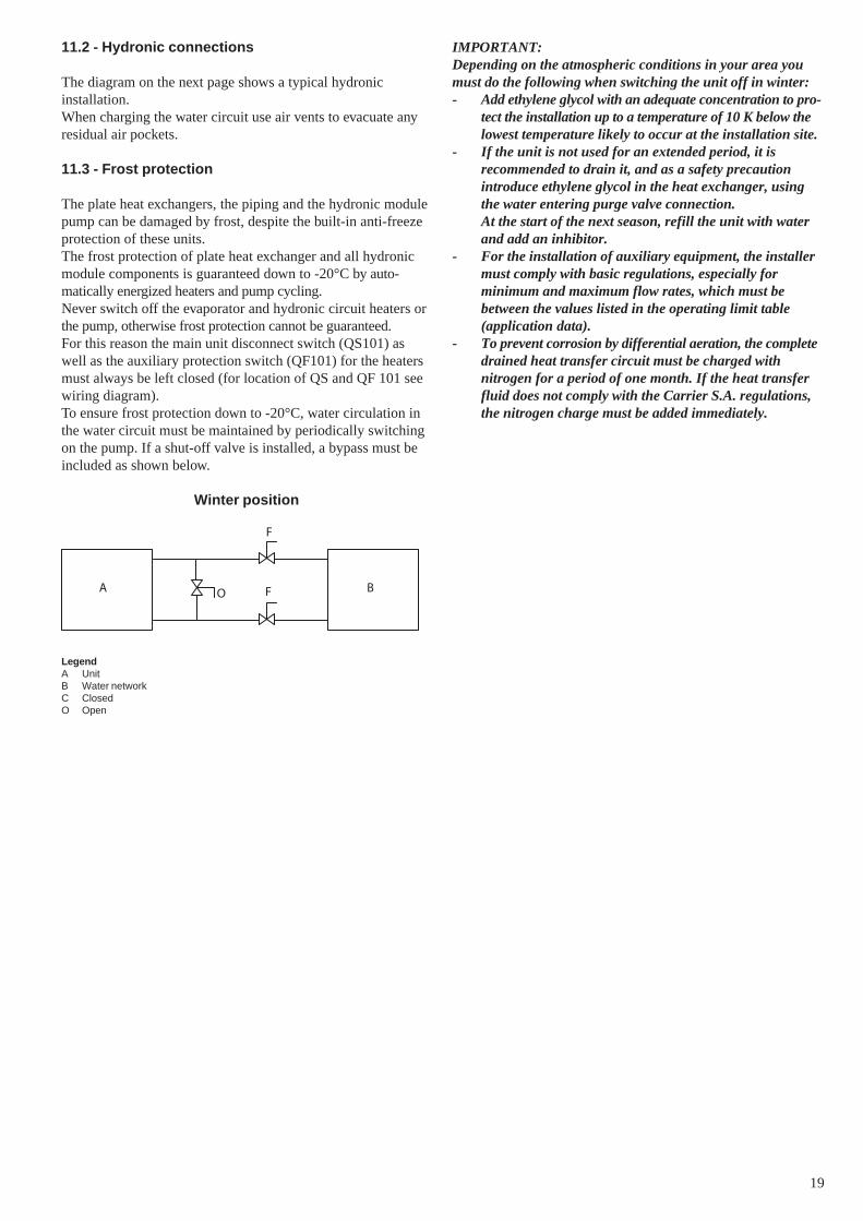
11.2 - Hydronic connections
The diagram on the next page shows a typical hydronicinstallation.When charging the water circuit use air vents to evacuate anyresidual air pockets.
11.3 - Frost protection
The plate heat exchangers, the piping and the hydronic modulepump can be damaged by frost, despite the built-in anti-freezeprotection of these units.The frost protection of plate heat exchanger and all hydronicmodule components is guaranteed down to -20°C by auto-matically energized heaters and pump cycling.Never switch off the evaporator and hydronic circuit heaters orthe pump, otherwise frost protection cannot be guaranteed.For this reason the main unit disconnect switch (QS101) aswell as the auxiliary protection switch (QF101) for the heatersmust always be left closed (for location of QS and QF 101 seewiring diagram).To ensure frost protection down to -20°C, water circulation inthe water circuit must be maintained by periodically switchingon the pump. If a shut-off valve is installed, a bypass must beincluded as shown below.
Winter position
LegendA UnitB Water networkC ClosedO Open
A BO
F
F
IMPORTANT:Depending on the atmospheric conditions in your area youmust do the following when switching the unit off in winter:- Add ethylene glycol with an adequate concentration to pro-
tect the installation up to a temperature of 10 K below thelowest temperature likely to occur at the installation site.
- If the unit is not used for an extended period, it isrecommended to drain it, and as a safety precautionintroduce ethylene glycol in the heat exchanger, usingthe water entering purge valve connection.At the start of the next season, refill the unit with waterand add an inhibitor.
- For the installation of auxiliary equipment, the installermust comply with basic regulations, especially forminimum and maximum flow rates, which must bebetween the values listed in the operating limit table(application data).
- To prevent corrosion by differential aeration, the completedrained heat transfer circuit must be charged withnitrogen for a period of one month. If the heat transferfluid does not comply with the Carrier S.A. regulations,the nitrogen charge must be added immediately.

20
Installation components
12 Air vent13 Thermometer sleeve14 Flexible connection15 Check valve16 System water drain plug (on connection pipe supplied in the unit)17 Pressure gauge18 Freeze-up protection bypass valve (when valve No. 15 are closed during
winter)19 Charge valve
--- Hydronic module (unit with hydronic module)
Note:Units without hydronic module (option) are equipped with a flow switch and aninternal piping heater.
Legend
Components of the unit and hydronic module
1 Victaulic screen filter2 Expansion tank3 Safety valve4 Available pressure pump5 Purge valve and pressure tap6 Pressure gauge to measure the plate heat exchanger pressure drop (to be
isolated with valve No. 5 if not used)7 System air vent8 Flow switch9 Flow control valve10 Plate heat exchanger11 Evaporator defrost heater
Typical hydronic circuit diagram (30RA 040-160)
1
2
3
4
5
6
75
8
10
11
9
18
15
1714
1417
15
16
13
19
13
12

21
12 - NOMINAL SYSTEM WATER FLOW CONTROL
The water circulation pumps of the 30RA units have been sizedto allow the hydronic modules to cover all possible configurat-ions based on the specific installation conditions, i.e. forvarious temperature differences between the entering and theleaving water (∆T) at full load, which can vary between 3 and10°C.
This required difference between the entering and leaving watertemperature determines the nominal system flow rate. It isabove all absolutely necessary to know the nominal system flowrate to allow its control via a manual valve provided in the waterleaving piping of the module (item 9 in the typical hydroniccircuit diagram).
With the pressure loss generated by the control valve in thehydronic system, the valve is able to impose the system pressure/flow curve on the pump pressure/flow curve, to obtain thedesired operating point (see example for 30RA 100). The pres-sure drop reading in the plate heat exchanger is used to controland adjust the nominal system flow rate. The pressure drop ismeasured with the pressure gauge connected to the heatexchanger water inlet and outlet.
Use this specification for the unit selection to know the systemoperating conditions and to deduce the nominal air flow as wellas the plate heat exchanger pressure drop at the specified con-ditions. If this information is not available at the system start-up, contact the technical service department responsible for theinstallation to get it.
These characteristics can be obtained from the technicalliterature using the unit performance tables for a ∆T of 5 K atthe evaporator or with the Electronic Catalogue selectionprogram for all ∆T conditions other than 5 K in the range of 3to 10 K.
12.1 - Water flow control procedure
As the total system pressure drop is not known exactly at thestart-up, the water flow rate must be adjusted with the controlvalve provided to obtain the specific flow rate for this applica-tion.
Proceed as follows:Open the valve fully (approximately 9 turns counter-clockwise).
Start-up the pump using the forced start command (refer to thecontrols manual) and let the pump run for two consecutivehours to clean the hydronic circuit of the system (presence ofsolid contaminants).
Read the plate heat exchanger pressure drop by taking thedifference of the readings of the pressure gauge connected tothe plate heat exchanger inlet and outlet, using valves (seediagrams below), and comparing this value after two hours ofoperation.
O
F F
O
F
F
O
O
F
LegendO OpenF Closed
Water inlet
Water outlet
Pressure gauge
NOTE: Applies to units 040 to 160
If the pressure drop has increased, this indicates that the screenfilter must be removed and cleaned, as the hydronic circuitcontains solid particles. In this case close the shutoff valves atthe water inlet and outlet and remove the screen filter afteremptying the hydronic section of the unit.
Renew, if necessary, to ensure that the filter is not contami-nated. Purge the air from the circuit (see 'Air vent' diagram).
Entering water pressure reading
Leaving water pressure reading
Air vent

22
When the circuit is cleaned, read the pressures at thepressure gauge (entering water pressure - leaving waterpressure), expressed in bar and convert this value to kPa(multiply by 100) to find out the plate heat exchangerpressure drop.
Compare the value obtained with the theoretical selection value.If the pressure drop measured is higher than the value specifiedthis means that the flow rate in the plate heat exchanger (andthus in the system) is too high. The pump supplies an excessiveflow rate based on the global pressure drop of the application.In this case close the control valve one turn and read the newpressure difference.
Proceed by successively closing the control valve until youobtain the specific pressure drop that corresponds to the nominalflow rate at the required unit operating point.- If the system has an excessive pressure drop in relation to
the available static pressure provided by the pump, theresulting water flow rate will de reduced and thedifference between entering and leaving watertemperature of the hydronic module will be increased.
To reduce the pressure drops of the hydronic system, it isnecessary:- to reduce the individual pressure drops as much as
possible (bends, level changes, accessories, etc.)- to use a correctly sized piping diameter.- to avoid hydronic system extensions, wherever possible.
Water flow rate, l/s
Legend1 Pump curve, 30RA 1002 Plate heat exchanger pressure drop (to be measured with the pressure gauge
installed at the water inlet and outlet)3 Installation pressure drop with control valve wide open4 Installation pressure drop after valve control to obtain nominal flow rate
Pre
ssur
e dr
op, k
Pa
1
2
3
4
0
25
50
75
100
125
150
175
200
2 4 6 8 10
Pump curve and water flow control as a function ofthe system pressure drops
Example: 30RA 100 at Eurovent conditions of 4.8 l/s
23
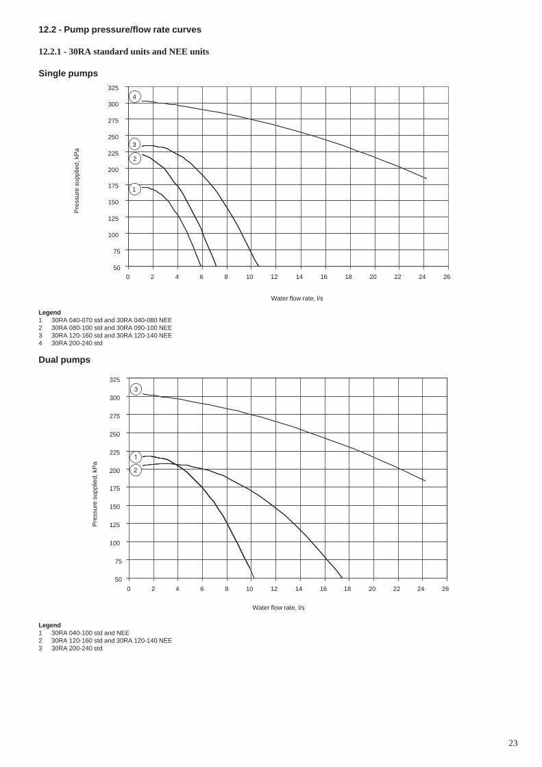
12.2 - Pump pressure/flow rate curves
12.2.1 - 30RA standard units and NEE units
Single pumpsP
ress
ure
supp
lied,
kP
a
Water flow rate, l/s
Legend1 30RA 040-070 std and 30RA 040-080 NEE2 30RA 080-100 std and 30RA 090-100 NEE3 30RA 120-160 std and 30RA 120-140 NEE4 30RA 200-240 std
Dual pumps
50
75
100
125
150
175
200
225
250
275
300
325
0 2 4 6 8 10 12 14 16 18 20 22 24 26
1
2
3
4
50
75
100
125
150
175
200
225
250
275
300
325
0 2 4 6 8 10 12 14 16 18 20 22 24 26
1
3
2
Legend1 30RA 040-100 std and NEE2 30RA 120-160 std and 30RA 120-140 NEE3 30RA 200-240 std
Pre
ssur
e su
pplie
d, k
Pa
Water flow rate, l/s
24
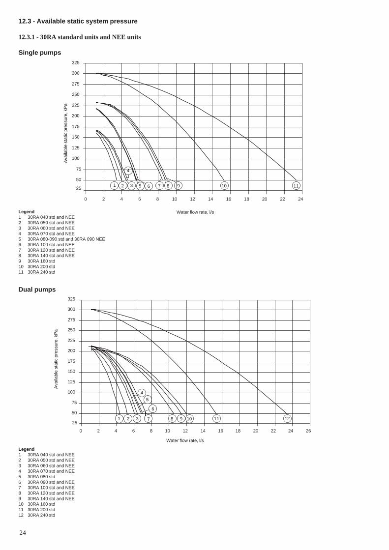
12.3 - Available static system pressure
12.3.1 - 30RA standard units and NEE units
Single pumps
Ava
ilabl
e st
atic
pre
ssur
e, k
Pa
Water flow rate, l/s
Ava
ilabl
e st
atic
pre
ssur
e, k
Pa
Water flow rate, l/s
Legend1 30RA 040 std and NEE2 30RA 050 std and NEE3 30RA 060 std and NEE4 30RA 070 std and NEE5 30RA 080-090 std and 30RA 090 NEE6 30RA 100 std and NEE7 30RA 120 std and NEE8 30RA 140 std and NEE9 30RA 160 std10 30RA 200 std11 30RA 240 std
Dual pumps
Legend1 30RA 040 std and NEE2 30RA 050 std and NEE3 30RA 060 std and NEE4 30RA 070 std and NEE5 30RA 080 std6 30RA 090 std and NEE7 30RA 100 std and NEE8 30RA 120 std and NEE9 30RA 140 std and NEE10 30RA 160 std11 30RA 200 std12 30RA 240 std
50
75
100
125
150
175
200
225
250
275
300
325
0 2 4 6 8 10 12 14 16 18 20 22 24
251 2 3
4
5 6 7 8 9 10 11
50
75
100
125
150
175
200
225
250
275
300
325
0 2 4 6 8 10 12 14 16 18 20 22 24 26
251 2 3
4
5
6
7 8 9 10 11 12

25
13 - START-UP
13.1 - Preliminary checks
- Never be tempted to start the chiller without reading fully,and understanding, the operating instructions and withouthaving carried out the following pre-start checks:
- Check the chilled water circulation pumps, air handlingunits and all other equipment connected to the evaporator.
- Refer to the manufacturer's instructions.- For units without hydronic module, the water pump
overheat protection device must be connected in serieswith the pump contactor power supply. If the pump is notsupplied with the unit (unit without hydronic module),verify that the power input of the field-installed pumpdoes not exceed the rating of the standard pump contactor,supplied in the control box (max. 3 kW for sizes 040 to160 and max. 5.5 kW for sizes 200 and 240).
- Refer to the wiring diagram supplied with the unit.- Ensure that there are no refrigerant leaks.- Confirm that all pipe securing bands are tight.- Confirm the the electrical connections are secure.
13.2 - Actual start-up
IMPORTANT• Commissioning and start-up of the chiller must be
supervised by a qualified refrigeration engineer.• Start-up and operating tests must be carried out with a
thermal load applied and water circulating in theevaporator.
• All set-point adjustments and control tests must becarried out before the unit is started up.
• Please refer to the controls section of this manual.
The unit should be started up in Local ON mode.Ensure that all safety devices are satisfied, especially the highpressure switches.
13.3 - Operation of two units in master/slave mode
The control of a master/slave assembly is in the entering waterand does not require any additional sensors (standard confi-guration). It can also be located in the leaving water. In this casetwo additional sensors must be added on the common piping.
All parameters, required for the master/slave function must beconfigured using the Service Configuration menu. All remotecontrols of the master/slave assembly (start/stop, set point, loadshedding etc.) are controlled by the unit configured as masterand must only be applied to the master unit.
IMPORTANT: The two units must be equipped with optionNo. 155 - CCN time scheduling and communications “ClockBoard”.
30RA 090 to 240 (with configuration: leaving watercontrol)
Depending on the installation and control type, each unit cancontrol its own water pump. If there is only one common pumpfor the two units, the master unit can control this. In this caseshut-off valves must be installed on each unit. They will beactivated at the opening and closing by the control of each unit(and the valves will be controlled using the dedicated waterpump outputs).
30RA 040 to 240 (standard configuration: return watercontrol)
Legend
1 Master unit2 Slave unit
Additional CCN board (one per unit, with connection via communicationbus)
Control boxes of the master and slave units
Water inlet
Water outlet
Water pumps for each unit (included as standard for units with hydronic
module)Additional sensors for leaving water control, to be connected to channel 1of the slave boards of each master and slave unitCCN communication busConnection of two additional sensors
21
1 2

26
Legend1 Saturated condensing temperature at the dew point2 Saturated liquid temperature at the bubble point3 Liquid refrigerant temperature4 Saturation curve at the dew point5 Saturation curbe at the bubble point6 Isotherms7 Apparent subcooling (1 - 3)8 Real subcooling (2 - 3)L LiquidL + V Liquid + vapourV Vapour
14.2.3 - PrinciplesRefrigeration installations must be inspected and maintainedregularly and rigorously by specialists. Their activities must beoverseen and checked by properly trained people. To minimisedischarge to the atmosphere, refrigerants and lubricating oilmust be transferred using methods which reduce leaks andlosses to a minimum and with materials that are suitable for theproducts.• Leaks must be repaired immediately• All units are equipped with two special connections on the
suction and liquid line, which permit the connection ofquick-connect recovery valves without loss of refrigerant.
• If the residual pressure is too low to make the transferalone, a purpose-built refrigerant recovery unit must beused.
• Compressor lubricating oil contains refrigerant. Any oildrained from a system during maintenance must thereforebe handled and stored accordingly.
• Refrigerant under pressure must never be discharged tothe atmosphere.
• If the refrigerant circuit is opened, plug all openings if theoperation takes up to one day, or charge the circuit withnitrogen for longer operations.
14 - MAINTENANCE
Any technician attending the machine for any purpose must befully qualified to work on refrigerant and electrical circuits.
All refrigerant charging, removal and draining operationsmust be carried out by a qualified technician and with thecorrect material for the unit. Any inappropriate handling canlead to uncontrolled fluid or pressure leaks.
WARNING: Before doing any work on the machine ensurethat the power is switched off. If a refrigerant circuit is opened,it must be evacuated, recharged and tested for leaks. Beforeany operation on a refrigerant circuit, it is necessary toremove the complete refrigerant charge from the unit with arefrigerant charge recovery group.
14.1 - General maintenance of the refrigerant circuit
• Keep the unit itself and the space around it clean and freeof obstructions. Remove all rubbish such as packingmaterials, as soon as the installation is completed.
• Regularly clean the exposed pipework to remove all dustand dirt. This makes detection of water leaks easier, andthey can be repaired before more serious faults develop.
• Confirm that all screwed and bolted connections andjoints are secure. Secure connections prevent leaks andvibration from developing.
• Check that all insulation joints are securely closed andthat all insulation is firmly in place. Check all heatexchangers and all pipework.
14.2 - Refrigerant charge
14.2.1 - Verification of the charge
CAUTION: The 30RA units are supplied with a preciserefrigerant charge (see Physical Data table).
To verify the correct system charge prodeed as follows:Ensure that no bubbles appear in the sight-glass, when operat-ing the unit at full load for a while, at a saturated condensingtemperature of between 55 and 57°C. If necessary cover a sec-tion of the coil surface to obtain this condensing temperature.Under these conditions the apparent subcooling which is equalto the saturated condensing temperature (1 - on the saturateddew point curve) minus the liquid refrigerant temperature (3)ahead of the expansion device must be between 12 and 14°C.This corresponds to an actual subcooling temperature ofbetween 5 and 7 K at the condenser outlet, depending on theunit type. Actual subcooling is equal the saturated liquidtemperature (2 - on the saturated bubble point curve) minus theliquid refrigerant temperature (3) ahead of the expansiondevice. Use the pressure tap supplied on the liquid piping tocharge refrigerant and to find out the pressure of the liquidrefrigerant. If the subcooling value is not correct, i.e. lowerthan the specified values, a leak detection test must be carriedout on the unit, as it no longer contains its original charge.
In order to measure the liquid refrigerant pressure and tempera-ture ahead of the expansion device, an access port must beopened on the expansion device which causes a slight air bypasson the condenser. Wait until unit operation has stabilized beforecarrying out pressure and temperature measurements.
Pre
ssur
e
Enthalpy
WARNING: To ensure proper operation of 30RA units theremust be at least 12 K of subcooling as the liquid refrigerantenters the expansion valve.
The 30RA units use refrigerant. For your information, we arereproducing here some extracts from the official publicationdealing with the design, installation, operation andmaintenance of air conditioning and refrigeration systemsand the training of people involved in these activities, agreedby the air conditioning and refrigeration industry.
14.2.2 - Apparent and actual subcooling
3
45
1
6
2
L
L + V
V
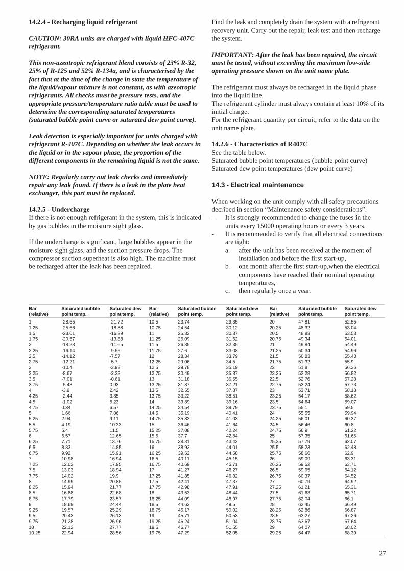
27
Bar Saturated bubble Saturated dew Bar Saturated bubble Saturated dew Bar Saturated bubble Saturated dew(relative) point temp. point temp. (relative) point temp. point temp. (relative) point temp. point temp.
1 -28.55 -21.72 10.5 23.74 29.35 20 47.81 52.551.25 -25.66 -18.88 10.75 24.54 30.12 20.25 48.32 53.041.5 -23.01 -16.29 11 25.32 30.87 20.5 48.83 53.531.75 -20.57 -13.88 11.25 26.09 31.62 20.75 49.34 54.012 -18.28 -11.65 11.5 26.85 32.35 21 49.84 54.492.25 -16.14 -9.55 11.75 27.6 33.08 21.25 50.34 54.962.5 -14.12 -7.57 12 28.34 33.79 21.5 50.83 55.432.75 -12.21 -5.7 12.25 29.06 34.5 21.75 51.32 55.93 -10.4 -3.93 12.5 29.78 35.19 22 51.8 56.363.25 -8.67 -2.23 12.75 30.49 35.87 22.25 52.28 56.823.5 -7.01 -0.61 13 31.18 36.55 22.5 52.76 57.283.75 -5.43 0.93 13.25 31.87 37.21 22.75 53.24 57.734 -3.9 2.42 13.5 32.55 37.87 23 53.71 58.184.25 -2.44 3.85 13.75 33.22 38.51 23.25 54.17 58.624.5 -1.02 5.23 14 33.89 39.16 23.5 54.64 59.074.75 0.34 6.57 14.25 34.54 39.79 23.75 55.1 59.55 1.66 7.86 14.5 35.19 40.41 24 55.55 59.945.25 2.94 9.11 14.75 35.83 41.03 24.25 56.01 60.375.5 4.19 10.33 15 36.46 41.64 24.5 56.46 60.85.75 5.4 11.5 15.25 37.08 42.24 24.75 56.9 61.226 6.57 12.65 15.5 37.7 42.84 25 57.35 61.656.25 7.71 13.76 15.75 38.31 43.42 25.25 57.79 62.076.5 8.83 14.85 16 38.92 44.01 25.5 58.23 62.486.75 9.92 15.91 16.25 39.52 44.58 25.75 58.66 62.97 10.98 16.94 16.5 40.11 45.15 26 59.09 63.317.25 12.02 17.95 16.75 40.69 45.71 26.25 59.52 63.717.5 13.03 18.94 17 41.27 46.27 26.5 59.95 64.127.75 14.02 19.9 17.25 41.85 46.82 26.75 60.37 64.528 14.99 20.85 17.5 42.41 47.37 27 60.79 64.928.25 15.94 21.77 17.75 42.98 47.91 27.25 61.21 65.318.5 16.88 22.68 18 43.53 48.44 27.5 61.63 65.718.75 17.79 23.57 18.25 44.09 48.97 27.75 62.04 66.19 18.69 24.44 18.5 44.63 49.5 28 62.45 66.499.25 19.57 25.29 18.75 45.17 50.02 28.25 62.86 66.879.5 20.43 26.13 19 45.71 50.53 28.5 63.27 67.269.75 21.28 26.96 19.25 46.24 51.04 28.75 63.67 67.6410 22.12 27.77 19.5 46.77 51.55 29 64.07 68.0210.25 22.94 28.56 19.75 47.29 52.05 29.25 64.47 68.39
14.2.4 - Recharging liquid refrigerant
CAUTION: 30RA units are charged with liquid HFC-407Crefrigerant.
This non-azeotropic refrigerant blend consists of 23% R-32,25% of R-125 and 52% R-134a, and is characterised by thefact that at the time of the change in state the temperature ofthe liquid/vapour mixture is not constant, as with azeotropicrefrigerants. All checks must be pressure tests, and theappropriate pressure/temperature ratio table must be used todetermine the corresponding saturated temperatures(saturated bubble point curve or saturated dew point curve).
Leak detection is especially important for units charged withrefrigerant R-407C. Depending on whether the leak occurs inthe liquid or in the vapour phase, the proportion of thedifferent components in the remaining liquid is not the same.
NOTE: Regularly carry out leak checks and immediatelyrepair any leak found. If there is a leak in the plate heatexchanger, this part must be replaced.
14.2.5 - UnderchargeIf there is not enough refrigerant in the system, this is indicatedby gas bubbles in the moisture sight glass.
If the undercharge is significant, large bubbles appear in themoisture sight glass, and the suction pressure drops. Thecompressor suction superheat is also high. The machine mustbe recharged after the leak has been repaired.
Find the leak and completely drain the system with a refrigerantrecovery unit. Carry out the repair, leak test and then rechargethe system.
IMPORTANT: After the leak has been repaired, the circuitmust be tested, without exceeding the maximum low-sideoperating pressure shown on the unit name plate.
The refrigerant must always be recharged in the liquid phaseinto the liquid line.The refrigerant cylinder must always contain at least 10% of itsinitial charge.For the refrigerant quantity per circuit, refer to the data on theunit name plate.
14.2.6 - Characteristics of R407CSee the table below.Saturated bubble point temperatures (bubble point curve)Saturated dew point temperatures (dew point curve)
14.3 - Electrical maintenance
When working on the unit comply with all safety precautionsdecribed in section “Maintenance safety considerations”.- It is strongly recommended to change the fuses in the
units every 15000 operating hours or every 3 years.- It is recommended to verify that all electrical connections
are tight:a. after the unit has been received at the moment of
installation and before the first start-up,b. one month after the first start-up,when the electrical
components have reached their nominal operatingtemperatures,
c. then regularly once a year.

28
14.4 - Condenser coil
We recommend, that finned coils are inspected regularly tocheck the degree of fouling. This depends on the environmentwhere the unit is installed, and will be worse in urban andindustrial installations and near trees that shed their leaves.
For coil cleaning proceed as follows:• Remove fibres and dust collected on the condenser face
with a soft brush (or vacuum cleaner).• Clean the coil with the appropriate cleaning agents.
We recommend TOTALINE products for coil cleaning:Part No. P902 DT 05EE: traditional cleaning methodPart No. P902 CL 05EE: cleaning and degreasing.
These products have a neutral pH value, do not contain phos-phates, are not harmful to the human body, and can be disposedof through the public drainage system. Depending on thedegree of fouling both products can be used diluted or undiluted.
For normal maintenance routines we recommend using 1 kg ofthe concentrated product, diluted to 10%, to treat a coil surfaceof 2 m2. This process can either be carried out with aTOTALINE applicator gun (part No. TE01 WA 4000EE) orusing a high-pressure spray gun in the low-pressure position.With pressurised cleaning methods care should be taken not todamage the coil fins. The spraying of the coil must be done:- in the direction of the fins- in the opposite direction of the air flow direction- with a large diffuser (25-30°)- at a distance of 300 mm.
The two cleaning products can be used for any of the followingcoil finishes: Cu/Cu, Cu/Al, Cu/Al with Polual, Blygold and/orHeresite protection.
It is not necessary to rinse the coil, as the products used are pHneutral. To ensure that the coil is perfectly clean, we recommendrinsing with a low water flow rate. The pH value of the waterused should be between 7 and 8.
WARNING: Never use pressurized water without a largediffusor. Concentrated and/or rotating water jets are strictlyforbidden.
Correct and frequent cleaning (approximately every threemonths) will prevent 2/3 of the corrosion problems.
Never use a fluid with a temperature above 45°C to clean theair heat exchangers.
15 - AQUASNAP MAINTENANCE PROGRAM
All maintenance operations must be carried out by technicianswho have been trained on Carrier products, observing allCarrier quality and safety standards.
Maintenance instructionsDuring the unit operating life the service checks and tests mustbe carried out in accordance with applicable national regulations.
If there are no similar criteria in local regulations, theinformation on checks during operation in annex C of standardEN 378-2 can be used.
External visual checks: annex A and B of standard EN 378-2
Corrosion checks: annex D of standard EN 378-2. Thesecontrols must be carried out:- After an intervention that is likely to affect the resistance
or a change in use or change of high-pressure refrigerant,or after a shut down of more than two years. Componentsthat do not comply, must be changed. Test pressuresabove the respective component design pressure must notbe applied (annex B and D).
- After repair or significant modifications or significantsystem or component extension (annex B)
- After re-installation at another site (annexes A, B and D)- After repair following a refrigerant leak (annex D). The
frequency of refrigerant leak detection can vary from onceper year for systems with less than 1% leak rate per yearto once a day for systems with a leak rate of 35% per yearor more. The frequency is in proportion with the leak rate.
NOTE: High leak rates are not acceptable. The necessarysteps must be taken to eliminate any leak detected.
NOTE 2: Fixed refrigerant detectors are not leak detectors,as they cannot locate the leak.
15.1 - Maintenance schedule
Regular maintenance is indispensable to optimise the operatinglife and reliability of the equipment. Maintenance operationsmust be carried out in accordance with the schedules below:
Service FrequencyA WeeklyB MonthlyC AnnuallyD Special cases
If the equipment does not operate normally during maintenanceoperations, please refer to the paragraph on diagnostics andbreakdowns of the '30RA/RY - 30RH/RYH “A” Pro-Dialog Plus'controls manual.
IMPORTANT: Before each equipment maintenanceoperation please ensure that:- the unit is in the OFF position- it is impossible for the unit to restart automatically
during maintenance.
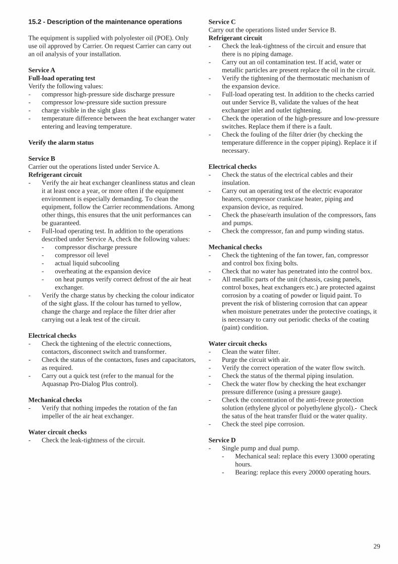
29
15.2 - Description of the maintenance operations
The equipment is supplied with polyolester oil (POE). Onlyuse oil approved by Carrier. On request Carrier can carry outan oil analysis of your installation.
Service AFull-load operating testVerify the following values:- compressor high-pressure side discharge pressure- compressor low-pressure side suction pressure- charge visible in the sight glass- temperature difference between the heat exchanger water
entering and leaving temperature.
Verify the alarm status
Service BCarrier out the operations listed under Service A.Refrigerant circuit- Verify the air heat exchanger cleanliness status and clean
it at least once a year, or more often if the equipmentenvironment is especially demanding. To clean theequipment, follow the Carrier recommendations. Amongother things, this ensures that the unit performances canbe guaranteed.
- Full-load operating test. In addition to the operationsdescribed under Service A, check the following values:- compressor discharge pressure- compressor oil level- actual liquid subcooling- overheating at the expansion device- on heat pumps verify correct defrost of the air heat
exchanger.- Verify the charge status by checking the colour indicator
of the sight glass. If the colour has turned to yellow,change the charge and replace the filter drier aftercarrying out a leak test of the circuit.
Electrical checks- Check the tightening of the electric connections,
contactors, disconnect switch and transformer.- Check the status of the contactors, fuses and capacitators,
as required.- Carry out a quick test (refer to the manual for the
Aquasnap Pro-Dialog Plus control).
Mechanical checks- Verify that nothing impedes the rotation of the fan
impeller of the air heat exchanger.
Water circuit checks- Check the leak-tightness of the circuit.
Service CCarry out the operations listed under Service B.Refrigerant circuit- Check the leak-tightness of the circuit and ensure that
there is no piping damage.- Carry out an oil contamination test. If acid, water or
metallic particles are present replace the oil in the circuit.- Verify the tightening of the thermostatic mechanism of
the expansion device.- Full-load operating test. In addition to the checks carried
out under Service B, validate the values of the heatexchanger inlet and outlet tightening.
- Check the operation of the high-pressure and low-pressureswitches. Replace them if there is a fault.
- Check the fouling of the filter drier (by checking thetemperature difference in the copper piping). Replace it ifnecessary.
Electrical checks- Check the status of the electrical cables and their
insulation.- Carry out an operating test of the electric evaporator
heaters, compressor crankcase heater, piping andexpansion device, as required.
- Check the phase/earth insulation of the compressors, fansand pumps.
- Check the compressor, fan and pump winding status.
Mechanical checks- Check the tightening of the fan tower, fan, compressor
and control box fixing bolts.- Check that no water has penetrated into the control box.- All metallic parts of the unit (chassis, casing panels,
control boxes, heat exchangers etc.) are protected againstcorrosion by a coating of powder or liquid paint. Toprevent the risk of blistering corrosion that can appearwhen moisture penetrates under the protective coatings, itis necessary to carry out periodic checks of the coating(paint) condition.
Water circuit checks- Clean the water filter.- Purge the circuit with air.- Verify the correct operation of the water flow switch.- Check the status of the thermal piping insulation.- Check the water flow by checking the heat exchanger
pressure difference (using a pressure gauge).- Check the concentration of the anti-freeze protection
solution (ethylene glycol or polyethylene glycol).- Checkthe satus of the heat transfer fluid or the water quality.
- Check the steel pipe corrosion.
Service D- Single pump and dual pump.
- Mechanical seal: replace this every 13000 operatinghours.
- Bearing: replace this every 20000 operating hours.
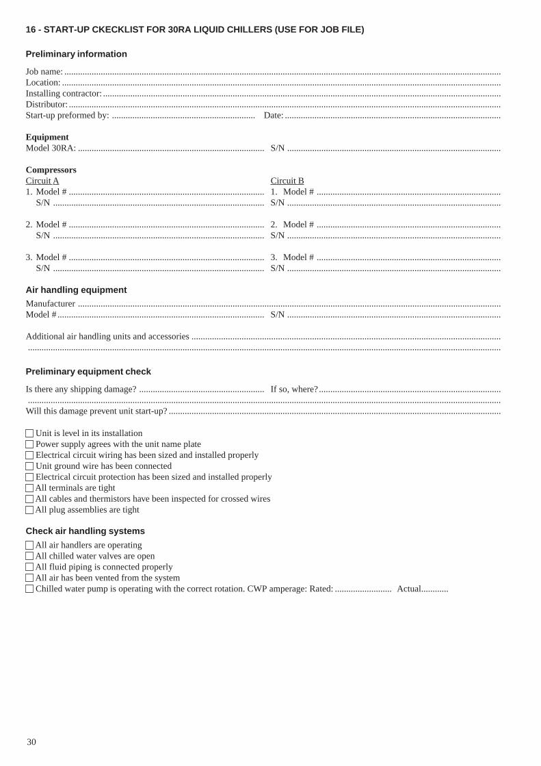
30
16 - START-UP CKECKLIST FOR 30RA LIQUID CHILLERS (USE FOR JOB FILE)
Preliminary information
Job name: ................................................................................................................................................................................................Location: .................................................................................................................................................................................................Installing contractor: ...............................................................................................................................................................................Distributor: ..............................................................................................................................................................................................Start-up preformed by: ............................................................... Date: ...............................................................................................
EquipmentModel 30RA: .................................................................................. S/N ..............................................................................................
CompressorsCircuit A Circuit B1. Model # ...................................................................................... 1. Model # .................................................................................
S/N ............................................................................................. S/N ..............................................................................................
2. Model # ...................................................................................... 2. Model # .................................................................................S/N ............................................................................................. S/N ..............................................................................................
3. Model # ...................................................................................... 3. Model # .................................................................................S/N ............................................................................................. S/N ..............................................................................................
Air handling equipment
Manufacturer ..........................................................................................................................................................................................Model # ........................................................................................... S/N ..............................................................................................
Additional air handling units and accessories ........................................................................................................................................................................................................................................................................................................................................................
Preliminary equipment check
Is there any shipping damage? ....................................................... If so, where? ................................................................................................................................................................................................................................................................................................Will this damage prevent unit start-up? ..................................................................................................................................................
Unit is level in its installation Power supply agrees with the unit name plate Electrical circuit wiring has been sized and installed properly Unit ground wire has been connected Electrical circuit protection has been sized and installed properly All terminals are tight All cables and thermistors have been inspected for crossed wires All plug assemblies are tight
Check air handling systems
All air handlers are operating All chilled water valves are open All fluid piping is connected properly All air has been vented from the system Chilled water pump is operating with the correct rotation. CWP amperage: Rated: ......................... Actual............
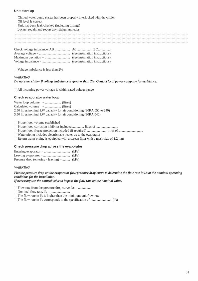
31
Unit start-up
Chilled water pump starter has been properly interlocked with the chiller Oil level is correct Unit has been leak checked (including fittings)Locate, repair, and report any refrigerant leaks
................................................................................................................................................................................................................
................................................................................................................................................................................................................
................................................................................................................................................................................................................
Check voltage imbalance: AB .................. AC ................. BC.................Average voltage = ..................................... (see installation instructions)Maximum deviation = .............................. (see installation instructions)Voltage imbalance = ................................. (see installation instructions) .
Voltage imbalance is less than 2%
WARNINGDo not start chiller if voltage imbalance is greater than 2%. Contact local power company for assistance.
All incoming power voltage is within rated voltage range
Check evaporator water loop
Water loop volume = ................... (litres)Calculated volume = ................... (litres)2.50 litres/nominal kW capacity for air conditioning (30RA 050 to 240)3.50 litres/nominal kW capacity for air conditioning (30RA 040)
Proper loop volume established Proper loop corrosion inhibitor included .............. litres of ........................... Proper loop freeze protection included (if required) ........................ litres of ............................. Water piping includes electric tape heater up to the evaporator Return water piping is equipped with a screen filter with a mesh size of 1.2 mm
Check pressure drop across the evaporator
Entering evaporator = ............................... (kPa)Leaving evaporator = ................................ (kPa)Pressure drop (entering - leaving) = ......... (kPa)
WARNING
Plot the pressure drop on the evaporator flow/pressure drop curve to determine the flow rate in l/s at the nominal operatingconditions for the installation.If necessary use the control valve to impose the flow rate on the nominal value.
Flow rate from the pressure drop curve, l/s = ................ Nominal flow rate, l/s = ....................... The flow rate in l/s is higher than the minimum unit flow rate The flow rate in l/s corresponds to the specification of ......................... (l/s)
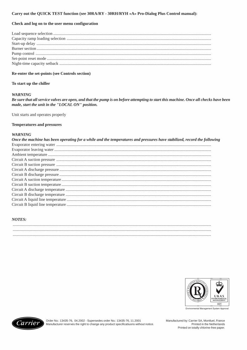
Carry out the QUICK TEST function (see 30RA/RY - 30RH/RYH «A» Pro-Dialog Plus Control manual):
Check and log on to the user menu configuration
Load sequence selection ........................................................................................................................................................Capacity ramp loading selection ...........................................................................................................................................Start-up delay ........................................................................................................................................................................Burner section ........................................................................................................................................................................Pump control .........................................................................................................................................................................Set-point reset mode ..............................................................................................................................................................Night-time capacity setback ..................................................................................................................................................
Re-enter the set-points (see Controls section)
To start up the chiller
WARNINGBe sure that all service valves are open, and that the pump is on before attempting to start this machine. Once all checks have beenmade, start the unit in the "LOCAL ON" position.
Unit starts and operates properly
Temperatures and pressures
WARNINGOnce the machine has been operating for a while and the temperatures and pressures have stabilized, record the followingEvaporator entering water .....................................................................................................................................................Evaporator leaving water .......................................................................................................................................................Ambient temperature .............................................................................................................................................................Circuit A suction pressure .....................................................................................................................................................Circuit B suction pressure .....................................................................................................................................................Circuit A discharge pressure ..................................................................................................................................................Circuit B discharge pressure ..................................................................................................................................................Circuit A suction temperature ................................................................................................................................................Circuit B suction temperature ................................................................................................................................................Circuit A discharge temperature ............................................................................................................................................Circuit B discharge temperature ............................................................................................................................................Circuit A liquid line temperature ...........................................................................................................................................Circuit B liquid line temperature ...........................................................................................................................................
NOTES:.............................................................................................................................................................................................................................................................................................................................................................................................................................................................................................................................................................................................
Order No.: 13435-76, 04.2002 - Supersedes order No.: 13435-76, 11.2001 Manufactured by: Carrier SA, Montluel, FranceManufacturer reserves the right to change any product specificatiuons without notice. Printed in the Netherlands
Printed on totally chlorine-free paper.