3d surface modeling using bentley context capture dr. duane brown history of photogrammetry center...
TRANSCRIPT

3D Surface Modeling UsingBentley Context Capture

Agenda
1. Multi-Ray Photogrammetry
• Brief Overview of Photogrammetry
• Aero-triangulation
• Self-Calibration
• Advent of Multi-ray and Computer Vision
(Microsoft Research and University of Washington)
• Sensors (Camera Systems)
• Camera Features Needed
• Sensors (Camera Systems)
• Sample Demo with Bentley Context Capture

A typical Aerial-Triangulation Layout

Aerial Triangulation - Bundle Adjustment
• Inpho
• Aerosys
• Leica LPS
• Socet GXP
• BLUH
• BINGO
• Intergraph
• Photomod
• Albany
• JFK
• PC Giant

Self-Calibration
Dr. Duane BrownHistory of PhotogrammetryCenter for Photogrammetric Training
Dr. Brown introduced Self- Calibration in the bundle adjustment.
Self calibration Improves:• the accuracy• the reliability of the photogrammetric adjustment
Anomalous Distortion
http://www.geodetic.com/v-stars/what-is-photogrammetry.aspx
ASPRS

Microsoft (ICE Project)https://www.microsoft.com/en-us/research/product/computational-photography-applications/image-composite-editor/

State of the Art Sensors
Dynamic Range (DR)
• Human eye - 90 dB
• Camera film - 80 dB
• CCD or CIS - 65 to 75 dB
• State of the art CIS - 150 dB
DR - brightest area and the darkest area animage sensor can process without saturation.
CCD – Couple Charged Device
CIS – CMOS Image Sensors
CMOS – Complimentary Metal Oxide Semiconductor
by Dawn Oosterhoff

CCD & CMOS Varied applications have varied requirements
• UAS
• Close Range
• Metrology
• Forensic
• Archeology
• Environmental
• Volumetric Surveys
• Autonomous Vehicles
• Microscopy
• Photogrammetry

Is Higher Megapixel better ?
Appreciably lower noise at high ISO
4928 x 3280
Does Size Matter? New Image Sensors Bring More Pixels, More Problems by Dawn Oosterhoff
The benchmark is a full-framed sensor—a sensor with the same dimensions as a frame of 35mm film; that is, 36 × 24 mm

Values to know !
Nikon D
Image Size 4928 x 3280Sensor Pixel Size 7.3 micronsSensor Resolution 16.2 MpSensor Size 35.9mm x 24.0mm
Image Resolution = 4928 x 3280 = 16.164 Mpix
Compute:Sensor ResolutionGiven Sensor Size &
Pixel Size =
35.9mm x 1000 = 35900 microns
24.0mm x 1000 = 24000 microns
35900/7.3 = 4917.80
24000/7.3 = 3287.67
35.9mm
24.0
mm Pixel Size
7.3 microns
4917.8 x 3287.67= 16.168 M pix
Compute:Sensor Size Given Image Size &
Pixel Size =
4928 x 7.3 = 35974.4 microns = 35974.4/1000 = 35.9 mm3280 x 7.3 = 23944 microns = 23944/1000 = 23.9 mm
4928 pixels
328
0 p
ixel
s
16.2 Mpix
Compute:Sensor Pixel Size Given Image Size & Sensor Size =
35.9 x 1000 = 35900 microns = 35900/4928 = 7.285 microns24.0 x 1000 = 24000 microns = 24000/3280 = 7.317 microns
Avg. Sensor Pixel Size = 7.3 microns

Multi-ray Photogrammetry
Multi-ray Photogrammetry• Multi-ray photogrammetry is not exactly a new technology,
rather a specific flight pattern with a very high forward overlap (80 percent, even 90 percent) and an increased sidelap (up to 60 percent). The result is considerable redundancy, critical for robust automated matching. One pixel on the ground is visible in up to 15 images
• Multi-ray photogrammetry has created a significant change in photogrammetry with the advent of the digital camera and a fully digital work flow.
“Photogrammetry versus Lidar: Clearing the Air” Alexander Wiechert is general manager at Vexcel Imaging GmbH, a Microsoft company in Austria. He holds degrees in Aerospace and Aeronautics and in Business Administration.
Dr. Michael Gruber is chief scientist at Vexcel Imaging GmbH.
Professional Surveyor Magazine

Current Softcopy Photogrammetric Systems
Modern Typical Methods – fast and accurate image matching
• RANSAC method find epipolar geometry• Efficient and fast detection algorithm• User defines number of points per image and matching method• Both Matching method are used default by BINGO Dr. Kruck & Co. GbR
Random Sample Consensus (RANSAC); Fischler and Bolles, 1987)

SIFTScale-Invariant Feature Transform (or SIFT) is an algorithm in computer vision to detect and describe local features in images. The algorithm was published by David Lowe in 1999.
Applications include object recognition, robotic mapping and navigation, image stitching, 3D modeling, gesture recognition, video tracking, individual identification of wildlife and match moving
https://www.youtube.com/watch?v=NPcMS49V5hg

From Photo to Point CloudStructured from Motion (SfM) Workflow
• Leica tridicon
• Trimble
• Topcon
• Pix 4D Mapper
• Agisoft
• 3D Correlator
• Bentley “Context Capture”
• Umapv
• Geoverse
Structure from Motion (SfM) revolutionary, low-cost, user-friendly photogrammetric technique for obtaininghigh-resolution datasets at a range of scales.
‘Structure-from-Motion’ photogrammetry: A low-cost, effective tool for geoscience applicationsM.J. Westoby a,⁎, J. Brasington b, N.F. Glasser a, M.J. Hambrey a, J.M. Reynolds

Agisoft (SfM) App using Digital Metric Sensor Images

FDOT Flight Planning – Leica Mission Pro
IMU/GPS boresight and Multi-ray Photogrammetry testing

Perry Airport FDOT boresight
2.5D surface Generated using Bentley’s Context Capture
Perry Airport 2.5 D surface - Over 300 images Bundle Adjusted with Bentley’s Context Capture
Imagery from FDOT-SMO - Zeiss DMC (2003) digital camera equipped with an upgraded CCD sensor

Perry Airport FDOT boresightPoint Cloud in Microstation Descartes
Digitized line featuresGenerate DTM
Close-up TIN

TERL Site- Tallahassee
Sony A6000
Focal Length (f) 50Pixel Size (Ps) 3.9Swath Along 4000Swath Across 6026

Inspections w/ Nikon Df
Focal Length (f) mm 50
Pixel Size (Ps) microns 5.2
Swath Along -pixels 4596
Swath Across -pixels 6923

Exported as POD file to Bentley Descartes

HWY Intersection w/ Nikon Df
AT by Sfm and Multi-ray
Nikon Df
Context Capture Workflow
Tie or Key Points

Final Textured 3D Surface

Photogrammetric Capture - The ‘3 x 3’ Rules
http://cipa.icomos.org/fileadmin/template/pdf/3x3-23_10_2013.pdf
3 .1 THE GEOMETRIC RULES1.1 – CONTROL• Measure long distances between well-define points• Define a minimum of one vertical distance (either using
plumb line or vertical features on the object ) and one horizontal.
• Do this on all sides of the object for control• Ideally, establish a network of 3D coordinated targets
or points from a loop traverse around the object.
1.2 - STEREO PHOTOCOVER• Take a ‘ring’ of pictures around the subject with overlap
of at least 60%. Some software needs 80% overlap.• Take shots from a height about half way up the subject
if possible.• Include the context or setting ground line, skyline, etc.• At each corner of the subject take a photo covering the
two adjacent sides.• Include the top, if possible (Aerial Obliques).• No image should lack overlap.• Add orthogonal, full facade shots for an overview and
rectification.
1.3- DETAIL STEREO PHOTOCOVERStereo-pairs should be taken:• Normal case (base-distance-ration 1:4 to 1:15), and/or• Convergent case (base-distance-ratio 1:1 to 1:15).• Close-up ‘square on’ stereo-pairs for detail • Measure control distances within overlaps• Check photography overlaps. If in doubt, add more shots • Measured distances for any potentially obscured areas.• Make sure enough control (at least 4 points is visible
in the stereo image area.
3. 3 - THE PROCEDURAL RULES3.1 - RECORD PHOTO LAYOUT • The ground plan with the direction of north indicated• The elevations of each facade (at an appropriate scale 1:50, 1:100 - 1:500).• Photo locations and directions (with frame numbers).• Single photo coverage and stereo coverage.• Control point locations, distances and plumb-lines.• If using ‘natural (photo)’ points a clear diagram showing each point is required.
3.2 - LOG THE METADATA Make witnessing diagrams of:
• Site name, location and geo-reference,• Owner’s name and address.• Date, weather and personnel. • Client commissioning body, artists, architects, permissions, obligations, etc.• Cameras and optics, focus and distance settings.• Calibration report, including the geometric and radiometric results if available.• Description of place, site, history, bibliography, etc.• Remember to document the process as you go.
3.3 - ARCHIVE Include the following:
• Data must be complete, stable, safe and accessible:• Check completeness and correctness before leaving the site.• Save images to a reliable location off the camera. • Save RAW formats and TIFF copies.• Remember a DVD is not forever !• Write down everything immediately• The original negatives/dia-positives/RAW files are archive documents. • Treat and keep them carefully.• Don’t cut into the format if cutting the original film. If using digital cameras, • don’t crop any of the images and use the full format.• Ensure the original and copies of the control data, site diagrams and• images are kept together, as a set, at separate sites on different media.
3 .2 - THE CAMERA RULES2.1 - CAMERA PROPERTIES• Fixed optics if possible. No zooming! Fully zoom-out. Do not use
shift optics. Disable auto-focus. • Fixed focus distance. Fix at infinity or a mean distance using
adhesive tape, but only use one distance for close-ups.• The image format frame of the camera must be sharply visible on
the images and have good contrast.• The true documents are the original dia-positives, negatives, or
digital ‘RAW’ equivalents. Set camera to use the camera its highest
quality format.
2.2 - CAMERA CALIBRATIONUse the best quality, highest resolution and largest format camera available.• ‘Medium’ format is better than a small format.• A larger sensor is better than a smaller one.• A wide-angle lens is better than a narrow angle for all round • photograph. Very wide-angle lenses should be avoided.• Calibrate the camera with a fixed focus lens and tape it there.• Standard calibration information is needed for each camera/lens• combination screen before capture with each lens will help.• A standardized color chart should be used in each sequence of
frames.
2.3- IMAGE EXPOSUREConsistent exposure and coverage is required.• Work with consistent illumination: beware deep dark shadows. • Use a lighting rig.• Use HDR to capture difficult, unbalanced exposures.• Plan for the best time of the day.• Use a tripod and cable release/remote control to• avoid camera movement and get sharp images.• Use a panoramic tripod head to get parallax-free panoramic• imagery.• Use the right mode: BW is best for tracing detail• but color is good for recording material type and pigment.• Use RAW or ‘high quality’ and ‘high sensitivity’ setting on• digital cameras.• Geotag the images. (pose or EO)

Earthworks Survey

Ground Control PointsFor Affine Transforms3 or More GCPs laid out in grid pattern is 0ptimum.
PID,N,E,Z LL WGS846,30.436890915195502,-84.274244734871402,30.9425,30.436893077778482,-84.274259106846131,30.9564,30.436916750462579,-84.274281393718539,30.9493,30.436910789491982,-84.274240358683386,30.9642,30.437032422138138,-84.274233011989523,31.5531,30.437036319796153,-84.274207122513403,30.994
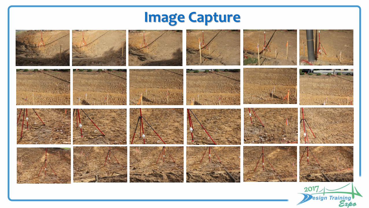
Image Capture
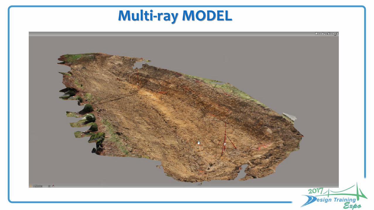
Multi-ray MODEL

WIREFRAME MODEL

DSM Point Cloud

Context Capture TIPS for TIFF 8bit uncompressed •JPEG •Tag Image File Format (TIFF) •Panasonic RAW (RW2) •Canon RAW (CRW, CR2) •Nikon RAW (NEF) •Sony RAW (ARW) •Hasselblad (3FR) •Adobe Digital Negative (DNG)
•Audio Video Interleave (AVI) •MPEG-1/MPEG-2 (MPG) •MPEG-4 (MP4) •Windows Media Video (WMV) •Quicktime (MOV)

Good Quality and Location of Ground Control Points (GCP)

Coordinate System LL WGS 84GPS tags, if present in Exif metadata or in an accompanying XMP file, are automatically extracted, and can be used to georeference the generated 3D model.
Incomplete GPS tags are ignored (with latitude and longitude coordinates but without altitude).
GPS altitude reference Sea level and WGS 84
ellipsoid are supported.

Set Data Tile Size to Maximize Processing Efficiency

Hardware Requirements for Context Capture
• CUDA Zonehttps://developer.nvidia.com/cuda-zone
CUDA® is a parallel computing platform and programming model invented by NVIDIA• http://www.nvidia.com/object/imaging_comp_vision.html
An Adequate graphics card that supports CUDA is very important !
Processor: 2 - IntelXeon®CPU ES-2620v3@ 2.4GHz – 64G RAMNVIDIA Quadro 6000 4G (GPU)

Performance ContextCapture exploits the power of general purpose computation on graphics processing units (GPGPU), yielding 50-times faster processing for some operations (image interpolation, rasterization, z-buffering). It also uses multi-core computing to speed up some CPU-intensive parts of the algorithms.
ContextCapture can process 10 to 20 gigapixels per day and per ContextCapture Engine on average, depending on the hardware configuration, for the production of a textured 3D mesh with Highest precision.
You can dramatically reduce processing time with grid computing, simply by running multiple ContextCaptureengines on several computers, and associate them to a same job queue.
Example: for vertical + 4-oblique aerial datasets with a ground resolution of 10-15 cm and a typical overlap, we have observed an average production rate of 30-50 km² per day on a cluster of 4 ContextCapture Engines.
Regarding memory use, one ContextCapture Engine with 8 GB of RAM can handle up to 1 gigapixel of input data and 10 million output triangles in one job.

Florida Department of Transportation
Closing…..Questions?
http://www.fdot.gov/geospatial/
Maurice Elliot, CP, GISP, MIEEEPhotogrammetry SupervisorFlorida Department of TransportationSurveying & Mapping Office605 Suwannee Street, MS 5-LTallahassee, FL 32399-0450Phone (850) [email protected]