4-cycle gas cultivator cultivadora a gasolina con …
TRANSCRIPT

769-23490 / 00 09/19
4-CYCLE GAS CULTIVATOR
CULTIVADORA A GASOLINA CON MOTOR DE 4 TIEMPOS
OPERATOR’S MANUAL | MANUAL DEL OPERADOR
1-888-331-4569 WWW.CRAFTSMAN.COM
IF YOU HAVE QUESTIONS OR COMMENTS, CONTACT US. SI TIENE DUDAS O COMENTARIOS, CONTÁCTENOS.
C405 CMXGVAMKC30A

2
All information, illustrations, and specifications in this manual are based on the latest product information available at the time of printing. We reserve the right to make changes at any time without notice. The product may vary slightly from the illustrations contained in this manual.
TABLE OF CONTENTS
Safety . . . . . . . . . . . . . . . . . . . . . . . . . . . . . . . . . . . . . . . . . . . . . . .2Know Your Unit . . . . . . . . . . . . . . . . . . . . . . . . . . . . . . . . . . . . . . . .6Specifications . . . . . . . . . . . . . . . . . . . . . . . . . . . . . . . . . . . . . . . . .6Assembly . . . . . . . . . . . . . . . . . . . . . . . . . . . . . . . . . . . . . . . . . . . . .7Oil and Fuel . . . . . . . . . . . . . . . . . . . . . . . . . . . . . . . . . . . . . . . . . . .8Starting and Stopping . . . . . . . . . . . . . . . . . . . . . . . . . . . . . . . . . .10Operation . . . . . . . . . . . . . . . . . . . . . . . . . . . . . . . . . . . . . . . . . . .11Maintenance . . . . . . . . . . . . . . . . . . . . . . . . . . . . . . . . . . . . . . . . .12Cleaning and Storage . . . . . . . . . . . . . . . . . . . . . . . . . . . . . . . . . .15Troubleshooting . . . . . . . . . . . . . . . . . . . . . . . . . . . . . . . . . . . . . .16Warranty . . . . . . . . . . . . . . . . . . . . . . . . . . . . . . . . . . . . . . . . . . . .19Service Numbers . . . . . . . . . . . . . . . . . . . . . . . . . . . . . .Back Cover
SAFETY
SPARK ARRESTOR NOTE
NOTE: For users on U.S. Forest Land and in the states of California, Maine, Oregon and Washington. All U.S. Forest Land and the state of California (Public Resources Codes 4442 and 4443), Oregon and Washington require, by law that certain internal combustion engines operated on forest brush and/or grass-covered areas be equipped with a spark arrestor, maintained in effective working order, or the engine be constructed, equipped and maintained for the prevention of fire. Check with your state or local authorities for regulations pertaining to these requirements. Failure to follow these requirements could subject you to liability or a fine. This unit is factory equipped with a spark arrestor. If it requires replacement, contact your local service dealer to install the appropriate muffler assembly.
Read the operator’s manual and follow all warnings and safety instructions. Failure to do so can result in serious injury to the operator and/or bystanders.
SYMBOL MEANING
WARNING: Signals a SERIOUS hazard. Failure to obey a safety WARNING signal CAN result in serious injury to yourself or to others.
CAUTION: Signals a MODERATE hazard. Failure to obey a safety CAUTION signal MAY result in property damage or injury to yourself or to others.
The purpose of safety symbols is to attract your attention to possible dangers. The safety symbols, and their explanations, deserve your careful attention and understanding. The safety warnings do not by themselves eliminate any danger. The instructions or warnings they give are not substitutes for proper accident prevention measures.
NOTE: Advises you of information or instructions vital to the operation or maintenance of the equipment.
DANGER: Signals an EXTREME hazard. Failure to obey a safety DANGER signal WILL result in serious injury or death to yourself or to others.
WARNING: This product can expose you to chemicals including engine exhaust, which is known to the State of California to cause cancer, and carbon monoxide, which is known to the State of California to cause birth defects or other reproductive harm. For more information go to www.P65Warnings.ca.gov.

3
• IMPORTANT SAFETY INSTRUCTIONS •
READ ALL INSTRUCTIONS BEFORE OPERATING
• Read the instructions carefully. Be familiar with the controls and proper use of the unit. Know how to stop the unit and disengage the controls quickly.
• Stay alert. Do not operate this unit when tired, ill or under the influence of alcohol, drugs or medication.
• Never allow children to operate the unit. Teens must be trained, accompanied and supervised by an adult. Never allow adults to operate the unit without proper instruction.
• All guards and safety attachments must be installed properly before operating the unit.
• Inspect the unit before use. Check for damaged parts. Check for fuel leaks. Make sure all parts operate properly. Make sure all fasteners are in place and secure. Make sure all moving parts are properly aligned and are not bound. Replace parts that are cracked, chipped, or damaged in any way. Have all damaged or improperly working parts repaired or replaced by an authorized service center. Do not operate the unit with loose or damaged parts.
• Be aware of risk of injury to the head, hands and feet. • Carefully inspect the area before starting the unit. Remove
rocks, broken glass, nails, wire, string and other objects that may be thrown or become entangled with the unit.
• Clear the area of children, bystanders and pets; keep them outside a 50-foot (15 m) radius, at a minimum. Even then, they are still at risk from thrown objects. Encourage bystanders to wear eye protection. If you are approached, stop the unit immediately.
• Squeeze the throttle control and check that it returns automatically to the idle position. Make all adjustments or repairs before using the unit.
• Do not change the engine governor settings or overspeed the engine.
• This unit is intended for occasional, household use only.
WARNING: When using the unit, all safety instructions must be followed. Please read these instructions before operating the unit in order to ensure the safety of the operator and any bystanders. Please keep these instructions for later use.
WHILE OPERATING
• Wear safety glasses or goggles that meet current ANSI / ISEA Z87.1 standards and are marked as such. Wear ear/hearing protection when operating this unit. Wear a face mask or dust mask if the operation is dusty.
• Wear heavy long pants, boots, gloves and a long sleeve shirt. Do not wear loose clothing, jewelry, short pants, sandals or go barefoot. Secure hair above shoulder level.
• Wear protective footwear that will improve footing on slippery surfaces.
• The tines should remain stationary when the engine idles. If they do not, refer to Adjusting the Idle Speed.
• Make sure the tines are not in contact with anything before starting the unit.
• Use the unit only in daylight or good artificial light. • Avoid accidental starting. Be in the starting position whenever
pulling the starter rope. The operator and unit must be in a stable position while starting. Refer to Starting and Stopping.
• Use the right tool. Only use this tool for its intended purpose. Only use the unit as described in this manual.
• Always hold the unit with both hands when operating. Keep a firm grip on the handle.
• Do not overreach. Always keep proper footing and balance. Take extra care when working on stairs, steep slopes or inclines.
• Use extreme caution when reversing or pulling the unit towards you.
• Keep hands, face, and feet away from all moving parts. Do not touch or try to stop moving parts.
• Do not touch the engine, gear housing or muffler. These parts get extremely hot from operation, even after the unit is turned off.
• Do not operate the unit faster than the speed needed to do the job. Do not run the unit at high speed when not in use.
• Do not force the unit. It will do a better, safer job when used at the intended rate.
SAFETY WARNINGS FOR GAS UNITS
• Store fuel only in containers specifically designed and approved for the storage of such materials.
• Always stop the engine and allow it to cool before filling the tank. Never remove the fuel tank cap or add fuel when the engine is hot. Always loosen the fuel tank cap slowly to relieve any pressure in the tank before fueling.
• Always add fuel in a clean, well-ventilated outdoor area where there are no sparks or flames. DO NOT smoke.
• Never operate the unit without the fuel cap securely in place. • Avoid creating a source of ignition for spilled fuel. Wipe up any
spilled fuel from the unit immediately, before starting the unit. Move the unit at least 30 ft. (9.1 m) from the fueling source and site before starting the engine. DO NOT smoke.
• Never start or run the unit inside a closed room or building. Breathing exhaust fumes can kill. Operate this unit only in a well-ventilated outdoor area.
WARNING: Gasoline is highly flammable and its vapors can explode if ignited. Take the following precautions:

4
• Always turn the unit off when operation is delayed or when moving from one location to another. Make sure all moving parts come to a complete stop.
• If the unit strikes or becomes entangled with a foreign object, stop the unit immediately. Check for damage. If damaged, do not restart or operate the unit until it is repaired. Do not operate the unit with loose or damaged parts.
• Turn the engine off and disconnect the spark plug for maintenance or repair.
• Use only original equipment manufacturer (OEM) replacement parts and accessories for this unit. These are available from your authorized service dealer. Use of any other parts or accessories could lead to serious injury to the user, or damage to the unit, and void the warranty.
• Keep the unit clean. Carefully remove vegetation and other debris that could block moving parts.
• To reduce fire hazard, replace a faulty muffler and spark arrestor. Keep the engine and muffler free from grass, leaves, excessive grease or carbon build up.
• If the unit starts to vibrate abnormally, stop the unit immediately. Inspect the unit for the cause of the vibration. Vibration is generally an indicator of trouble.
• Use caution when cultivating in hard ground. The tines may catch in the ground and propel the unit forward. If this occurs, release the handlebar(s) and do not restrain the unit.
OTHER SAFETY WARNINGS
• Maintain the unit with care. Follow all maintenance instructions in this manual.
• Do not perform maintenance procedures other than those described in this manual. All service, other than the maintenance procedures described in this manual, should be performed by an authorized service dealer.
• Never remove, modify or make inoperative any safety device furnished with the unit.
• Before inspecting, maintaining, cleaning, storing, transporting or replacing any parts on the unit: 1. Stop the unit. Refer to Starting and Stopping. 2. Make sure all moving parts have stopped. 3. Allow the unit to cool. 4. Disconnect the spark plug wire.
• Secure the unit while transporting. • Never store the unit with fuel in the tank, inside a building where
fumes may reach an open flame (pilot lights, etc.) or sparks (switches, electrical motors, etc.).
• Store the unit in a dry place, secured or at a height to prevent unauthorized use or damage. Keep the unit out of the reach of children.
• Never douse or squirt the unit with water or any other liquid. Keep handles dry and clean (free from debris, oil and grease). Clean the unit after each use. Refer to Cleaning and Storage. Do not use solvents or strong detergents.
• Clean the tines with water. Oil the tines with machine oil to prevent rust.
• Keep these instructions. Refer to them often and use them to instruct other users. If you loan this unit to others, also loan them these instructions.
SAVE THESE INSTRUCTIONS

5
• SAFETY & INTERNATIONAL SYMBOLS • This operator's manual describes safety and international symbols and pictographs that may appear on this product. Read the operator's manual for complete safety, assembly, operating and maintenance and repair information.
SYMBOL MEANING SYMBOL MEANING
• SAFETY ALERT SYMBOL
Indicates danger, warning or caution. May be used in conjunction with other symbols or pictographs.
• READ OPERATOR'S MANUAL
WARNING: Read the operator’s manual(s) and follow all warnings and safety instructions. Failure to do so can result in serious injury to the operator and/or bystanders.
• WEAR EYE AND HEARING PROTECTION
WARNING: Thrown objects and loud noise can cause severe eye injury and hearing loss. Wear eye protection meeting current ANSI / ISEA Z87.1 standards and ear protection when operating this unit. Use a full face shield when needed.
• WEAR FOOT PROTECTION
Always wear heavy-duty, non-slip footwear when operating this unit.
• WEAR HAND PROTECTION
Always wear heavy-duty, non-slip gloves when handling this unit.
• UNLEADED FUEL
Always use clean, fresh unleaded fuel.
• OIL
Refer to operator’s manual for the proper type of oil.
• DO NOT USE E85 FUEL IN THIS UNIT
CAUTION: It has been proven that fuel containing greater than 10% ethanol will likely damage this engine and void the warranty.
• ON/OFF STOP CONTROL
ON / START / RUN
• ON/OFF STOP CONTROL
OFF or STOP
• PRIMER BULB
Push primer bulb, fully and slowly, 10 times.
• THROWN OBJECTS CAN CAUSE SEVERE INJURY
WARNING: Small objects can be propelled at high speed, causing injury.
• KEEP BYSTANDERS AWAY
WARNING: Keep all bystanders, especially children and pets, at least 50 feet (15 m) from the operating area.
• HOT SURFACE
WARNING: Do not touch a hot engine, gear housing or muffler. You may get burned. These parts get extremely hot from operation. When turned off, they remain hot for a short time.
• GARDEN CULTIVATORS – ROTATING TINES CAN CAUSE SEVERE INJURY
WARNING: Stop the engine and allow the tines to stop moving before installing or removing the tines, or before cleaning or performing any maintenance. Keep hands and feet away from rotating tines.
• NO STEP Always keep proper footing and balance. Do not overreach, take extra care when working on steep slopes or inclines.
• PLACE RIGHT FOOT HERE
Avoid accidental starting. Be in the starting position whenever pulling the starter rope. The operator and unit must be in a stable position while starting.

Fuel Cap
Handlebar
Starter Rope Grip
Throttle Control
Spark Plug
Muffler
On/Off Switch
Primer Bulb
Air Filter Cover
Oil Fill Plug
Wheel AssemblyTine Guard
Tines
Gear Box
Knobs
6
KNOW YOUR UNIT
APPLICATIONS
• Cultivating sod and light to medium soil • Cultivating in garden areas, around trees, etc.
Engine Type . . . . . . . . . . . . . . . . . . . . . . . . . . . . . . . . . . . . . . . . . . . . . . . . . . . . . . . . . . . . . . . . . . . . . . . . . . . . . . . . . . . . . . . Air-Cooled, 4-CycleDisplacement. . . . . . . . . . . . . . . . . . . . . . . . . . . . . . . . . . . . . . . . . . . . . . . . . . . . . . . . . . . . . . . . . . . . . . . . . . . . . . . . . . . . . . . 30 cc (1.83 cu. in.) Spark Plug Gap. . . . . . . . . . . . . . . . . . . . . . . . . . . . . . . . . . . . . . . . . . . . . . . . . . . . . . . . . . . . . . . . . . . . . . . . . . . . . . . . . . 0.025 inch (0.635 mm)Spark Plug . . . . . . . . . . . . . . . . . . . . . . . . . . . . . . . . . . . . . . . . . . . . . . . . . . . . . . . . . . . . . . . . . . . . . . . . . Champion® RDZ4H or equivalent plugLubrication . . . . . . . . . . . . . . . . . . . . . . . . . . . . . . . . . . . . . . . . . . . . . . . . . . . . . . . . . . . . . . . . . . . . . . . . . . . . . . . . . . . . . . . . . . . . . . . SAE 30 OilCrankcase Oil Capacity . . . . . . . . . . . . . . . . . . . . . . . . . . . . . . . . . . . . . . . . . . . . . . . . . . . . . . . . . . . . . . . . . . . . . . . . . . . . . . . . . 3.04 oz. (90 ml)Fuel Tank Capacity . . . . . . . . . . . . . . . . . . . . . . . . . . . . . . . . . . . . . . . . . . . . . . . . . . . . . . . . . . . . . . . . . . . . . . . . . . . . . . . . . . . . . . 15 oz. (444 ml)Cultivating Path Width (Maximum) . . . . . . . . . . . . . . . . . . . . . . . . . . . . . . . . . . . . . . . . . . . . . . . . . . . . . . . . . . . . . . . . . . . . . 12 inches (30.5 cm)Cultivating Depth (Maximum) . . . . . . . . . . . . . . . . . . . . . . . . . . . . . . . . . . . . . . . . . . . . . . . . . . . . . . . . . . . . . . . . . . . . . . . . . . 6 inches (15.2 cm)Approximate Unit Weight (No fuel) . . . . . . . . . . . . . . . . . . . . . . . . . . . . . . . . . . . . . . . . . . . . . . . . . . . . . . . . . . . . . . . 30 - 31 lbs. (13.6 - 14.1 kg)
SPECIFICATIONS*
* All specifications are based on the latest product information available at the time of printing. We reserve the right to make changes at any time without notice.
NO ASSEMBLY TOOLS REQUIRED

7
ASSEMBLY
Fig. 2
Cotter Pin
INSTALLING AND ADJUSTING THE WHEEL ASSEMBLY
Installing the Wheel Assembly
1. Insert the wheel assembly into the wheel bracket. The "J" shape of the wheel assembly should point away from the unit (Fig. 1).
2. Align the hole in the wheel bracket with the desired hole in the wheel assembly (Fig. 1).
3. Insert the clevis pin through the aligned holes (Fig. 2). 4. Insert the cotter pin into the clevis pin (Fig. 2). NOTE: It may be necessary to adjust the position of the wheel
assembly before using the unit.
Adjusting the Wheel Assembly
1. Remove the cotter pin from the clevis pin (Fig. 2). 2. Remove the clevis pin from the wheel bracket and wheel
assembly (Fig. 2). 3. Align the hole in the wheel bracket with the desired hole in the
wheel assembly (Fig. 1). NOTE: Moving the wheel assembly down will raise the wheel height.
Moving the wheel assembly up will lower the wheel height. 4. Insert the clevis pin through the aligned holes (Fig. 2). 5. Insert the cotter pin into the clevis pin (Fig. 2).
Fig. 1
Wheel Assembly
Wheel Bracket
Clevis Pin
WARNING: To avoid serious personal injury, the wheel assembly must be installed before operating the unit.
WARNING: To avoid injury from the tines, wear heavy gloves and a long sleeve shirt when installing or adjusting the wheel assembly.
Lower
Raise
Fig. 3
Fig. 4
Knobs
POSITIONING THE HANDLEBAR
1. Set the unit upright. 2. Loosen the knobs (Fig. 4). 3. Swing the handlebar up into the operating position (Fig. 3). NOTE: Take care not to pinch the cables when positioning the
handlebar (Fig. 4). 4. Tighten the knobs securely. NOTE: Do not over tighten the knobs. 5. Readjust the cables so they are smooth and tight against the
handlebar.
Knobs
Cables

8
OIL AND FUEL
USING THE RIGHT OIL
Use a high-quality SAE 30 weight oil. DO NOT use dirty oil. Failure to use clean oil of the correct type can cause premature engine wear and failure.
Fig. 5
Fig. 6
Oil Fill Plug
Oil Fill Hole
O-Ring
ADDING OIL: INITIAL USE
NOTE: This unit was shipped without oil in the crankcase. Oil must be added before starting the unit.
NOTE: Never add oil to the fuel tank. This unit has a four-cycle engine. DO NOT mix oil with gasoline.
1. Set the unit on a flat, level surface. Tip the unit back so that the handlebar touches the ground and the engine is in a horizontal position (Fig. 5).
2. Unscrew the oil fill plug (Fig. 6). 3. Pour 3.04 fluid oz. (90 ml) of oil into the oil fill hole (Fig. 6). NOTE: This unit comes with a 3.04 fluid oz. (90 ml) container of oil. NOTE: DO NOT overfill. Refer to Checking the Oil Level. 4. Wipe up any oil that may have spilled. 5. Make sure the O-ring is in place on the oil fill plug (Fig. 6). 6. Reinstall the oil fill plug.
WARNING: OVERFILLING THE CRANKCASE MAY CAUSE SERIOUS PERSONAL INJURY.
9
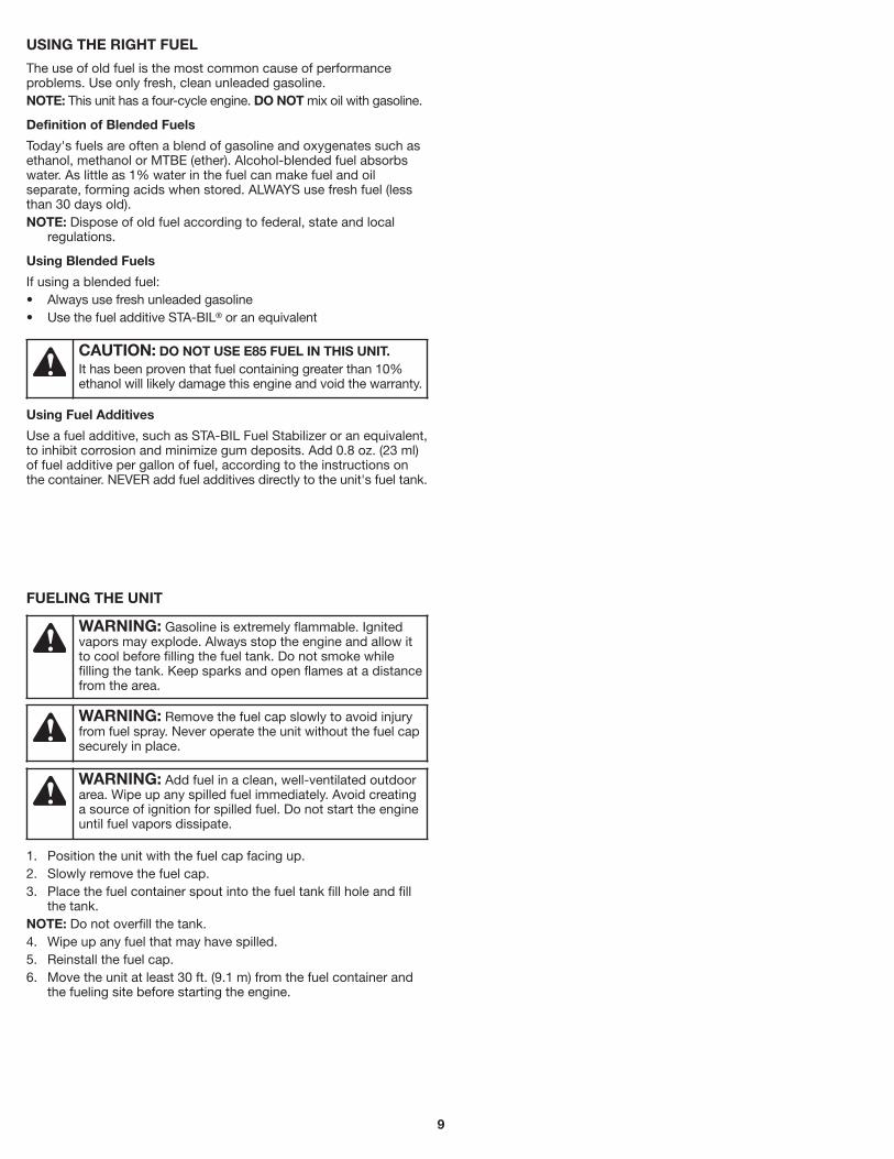
FUELING THE UNIT
1. Position the unit with the fuel cap facing up. 2. Slowly remove the fuel cap. 3. Place the fuel container spout into the fuel tank fill hole and fill
the tank. NOTE: Do not overfill the tank. 4. Wipe up any fuel that may have spilled. 5. Reinstall the fuel cap. 6. Move the unit at least 30 ft. (9.1 m) from the fuel container and
the fueling site before starting the engine.
WARNING: Gasoline is extremely flammable. Ignited vapors may explode. Always stop the engine and allow it to cool before filling the fuel tank. Do not smoke while filling the tank. Keep sparks and open flames at a distance from the area.
WARNING: Remove the fuel cap slowly to avoid injury from fuel spray. Never operate the unit without the fuel cap securely in place.
WARNING: Add fuel in a clean, well-ventilated outdoor area. Wipe up any spilled fuel immediately. Avoid creating a source of ignition for spilled fuel. Do not start the engine until fuel vapors dissipate.
USING THE RIGHT FUEL
The use of old fuel is the most common cause of performance problems. Use only fresh, clean unleaded gasoline. NOTE: This unit has a four-cycle engine. DO NOT mix oil with gasoline.
Definition of Blended Fuels
Today's fuels are often a blend of gasoline and oxygenates such as ethanol, methanol or MTBE (ether). Alcohol-blended fuel absorbs water. As little as 1% water in the fuel can make fuel and oil separate, forming acids when stored. ALWAYS use fresh fuel (less than 30 days old). NOTE: Dispose of old fuel according to federal, state and local
regulations.
Using Blended Fuels
If using a blended fuel: • Always use fresh unleaded gasoline • Use the fuel additive STA-BIL® or an equivalent
Using Fuel Additives
Use a fuel additive, such as STA-BIL Fuel Stabilizer or an equivalent, to inhibit corrosion and minimize gum deposits. Add 0.8 oz. (23 ml) of fuel additive per gallon of fuel, according to the instructions on the container. NEVER add fuel additives directly to the unit's fuel tank.
CAUTION: DO NOT USE E85 FUEL IN THIS UNIT. It has been proven that fuel containing greater than 10% ethanol will likely damage this engine and void the warranty.

10
WARNING: Operate this unit only in a well-ventilated outdoor area. Carbon monoxide exhaust fumes can be lethal in a confined area.
WARNING: Avoid accidentally starting the unit. To avoid serious injury, the operator and the unit must be in a stable position when pulling the starter rope (Fig. 9).
WARNING: The tines may rotate during the starting process. Always stand in the starting position. Use one foot to hold the wheels in place. Tilt the unit back slightly to bring the tines off the ground (Fig. 9).
STARTING AND STOPPING
STOPPING INSTRUCTIONS
1. Release the throttle control and allow the engine to idle. 2. Press and hold the On/Off switch in the Off (O) position until the
engine comes to a complete stop (Fig. 7).
STARTING INSTRUCTIONS
NOTE: There is no need to turn the unit on. The On/Off switch is in the On ( I ) position at all times (Fig. 7).
Before Starting the Unit 1. Check the oil level. Refer to Checking the Oil Level. 2. Fill the fuel tank. Refer to Fueling the Unit.
Starting the Unit
1. Slowly press and release the primer bulb 10 times (Fig. 8). 2. Stand in the starting position (Fig. 9). Hold the handlebar firmly
with one hand. Hold the starter rope with the other hand. Use one foot to hold the wheels in place.
3. Tilt the unit back slightly to bring the tines off the ground (Fig. 9). 4. Squeeze and hold the throttle control (Fig. 7). 5. Continue to hold the throttle control. Pull the starter rope with a
controlled and steady motion until the unit starts (Fig. 9). IF... the engine does not start after pulling the starter rope 10 times,
repeat the starting procedure. IF... the engine fails to start after 3 attempts, begin the starting
procedure with step 2. IF... the engine stops while the throttle control is squeezed, repeat
the starting procedure. IF THE ENGINE IS HOT... repeat the starting procedure.
Fig. 7
Throttle Control
On/Off Switch
I = On
O = Off
Fig. 9
Starting Position
Starter Rope Grip
Fig. 8
Primer Bulb

11
MOVING THE UNIT
1. Stop the engine. 2. Tilt the unit back until the tines clear the ground. 3. Push or pull the unit to the next location.
ADJUSTING THE TINE DEPTH
The tines should penetrate most garden soils approximately 4 to 5 inches. If necessary, adjust the tines as follows: 1. Stop the engine and allow it to cool. Grasp the spark plug wire
firmly and pull the cap from the spark plug. 2. Raise the wheel height for shallower tine penetration or lower
the wheel height for deeper tine penetration. Refer to Adjusting the Wheel Assembly in the Assembly Instructions section.
3. Reconnect the spark plug wire and continue use.
OPERATING TIPS
1. Move the cultivator to the work area prior to starting the engine. Refer to Moving the Unit.
2. Start the unit as described in the Starting Instructions. 3. Tilt the unit back until the tines clear the ground. 4. With the tines off the ground, squeeze the throttle control to
increase the engine speed. 5. Hold the handlebar firmly with both hands and slowly lower the
unit until the tines make contact with the ground (Fig. 10). 6. As cultivating action begins, pull back on the cultivator so that
the tines can penetrate the ground.
7. Once the ground has been broken, continue at a moderate pace until you are familiar with the controls and the handling of the cultivator.
8. Pull the cultivator backwards to improve the depth of cultivation and reduce your effort.
9. If the tines are digging too deep or not deep enough, adjust them according to Adjusting the Tine Depth.
OPERATION
WARNING: Dress properly to reduce the risk of injury when operating this unit. Do not wear loose clothing or jewelry. Wear eye and ear/hearing protection. Wear heavy long pants, boots and gloves. Do not wear short pants, sandals or operate barefoot.
WARNING: To prevent serious personal injury, never pick up or carry the unit while the engine is running.
WARNING: To prevent serious personal injury, always stop the engine when operation is delayed or when moving the unit from one location to another.
WARNING: To prevent serious personal injury, use extreme caution when reversing or pulling the unit towards you.
Fig. 10
Operating Position

12
MAINTENANCE
WARNING: To avoid serious personal injury, always stop the engine and allow it to cool before cleaning or maintaining the unit. Never perform cleaning or maintenance while the unit is running. Disconnect the spark plug wire to prevent the unit from starting accidentally.
WARNING: Wear protective clothing and observe all safety instructions to prevent serious personal injury.
MAINTENANCE SCHEDULE
Perform these required maintenance procedures at the frequency stated in the table. These procedures should also be a part of any seasonal tune-up. NOTE: Some maintenance procedures may require special tools or
skills. If you are unsure about these procedures, take the unit to an authorized service dealer. Call 1-888-331-4569 for more information.
NOTE: Maintenance, replacement, or repair of the emission control devices and system may be performed by an authorized service dealer. Call 1-888-331-4569 for more information.
NOTE: Please read the California/EPA statement that came with the unit for a complete listing of terms and coverage for the emissions control devices, such as the spark arrestor, muffler, carburetor, etc.
FREQUENCY MAINTENANCE REQUIREDEvery 10 hours • Clean and re-oil the air filter. Refer to
Maintaining the Air Filter.
After the first 10 hours and at 38 hours
• Change the oil. Refer to Changing the Oil. • Have the rocker arm clearance checked by
an authorized service dealer. • Check the spark plug condition and gap.
Refer to Maintaining the Spark Plug.
REPLACING THE TINES
All tines should be replaced at the same time because they will wear evenly through normal use. Work on one side at a time.
Preparing the Unit for Tine Removal
1. Stop the engine and allow it to cool. Grasp the spark plug wire firmly and pull the cap from the spark plug.
2. Set the unit on a flat, level surface. Tip the unit back so that the handlebar touches the ground and the engine is in a horizontal position (Fig. 13).
NOTE: It may be necessary to wash dirt off the tines and tine shafts before removing the tines.
Removing the Old Tines
1. Remove the cotter pin from the clevis pin (Fig. 11). Remove the clevis pin from the double tine and tine shaft.
2. Slide the tines off of the tine shaft. 3. Repeat this process for the other side.
Installing the New Tines
1. Clean and oil the tine shaft. 2. Slide the new tines onto the tine shaft. The hubs must face
toward each other (Fig. 12). Install the single tine first. Then install the double tine. Align the hole on the double tine with the hole on the tine shaft (Fig. 12).
3. Insert a clevis pin through the aligned holes (Fig. 11). Insert a cotter pin into the clevis pin.
4. Repeat this process for the other side. 5. Reconnect the spark plug wire.
WARNING: To prevent serious personal injury, always wear heavy gloves when handling the tines.
Fig. 11
Clevis Pin
Cotter Pin
Front View
Fig. 12
Single Tine
Double Tine
Tine Shaft
Hubs
HolesFront View

13
Fig. 13
Fig. 14
Oil Fill Plug
Oil Fill Hole
O-Ring
Fig. 15
Bottom Thread
Oil Fill Hole
Maximum Oil Level
CHANGING THE OIL
Change the oil while the engine is still warm. The oil will flow freely and carry away more impurities. 1. Clean the area around the oil fill plug (Fig. 14) to prevent debris
from entering the oil fill hole. 2. Unscrew the oil fill plug. 3. Tip the unit vertically to pour the oil out of the oil fill hole and into
a container (Fig. 16). Allow ample time for complete drainage. NOTE: Dispose of the old oil according to federal, state and local
regulations. 4. Wipe up any oil that may have spilled. 5. Pour 3.04 fl.oz. (90 ml) of SAE 30 oil into the oil fill hole. NOTE: DO NOT overfill. Refer to Checking the Oil Level. 6. Wipe up any oil that may have spilled. 7. Make sure the O-ring is in place on the oil fill plug (Fig. 14). 8. Reinstall the oil fill plug.
Fig. 16
CHECKING THE OIL LEVEL
1. Stop the engine and allow it to cool. 2. Set the unit on a flat, level surface. Tip the unit back so that
the handlebar touches the ground and the engine is in a horizontal position (Fig. 13).
NOTE: Failure to keep the engine level may result in oil overfill. 3. Clean the area around the oil fill plug (Fig. 14) to prevent debris
from entering the oil fill hole (Fig. 14). 4. Unscrew the oil fill plug. 5. Look into the oil fill hole; use a flashlight if necessary. The oil
level should just touch the bottom thread of the oil fill hole (Fig. 15). • If the oil level is too low, add a small amount of oil to the oil fill
hole until the oil is at the correct level.
• If the oil level is too high, tip the unit and drain the excess oil into an appropriate container (Fig. 16).
6. Wipe up any oil that may have spilled. 7. Make sure the O-ring is in place on the oil fill plug (Fig. 14). 8. Reinstall the oil fill plug.
WARNING: Check the oil level before each use. The importance of maintaining the proper oil level cannot be overemphasized.
WARNING: DO NOT overfill the crankcase. OVERFILLING THE CRANKCASE MAY CAUSE SERIOUS PERSONAL INJURY.
14
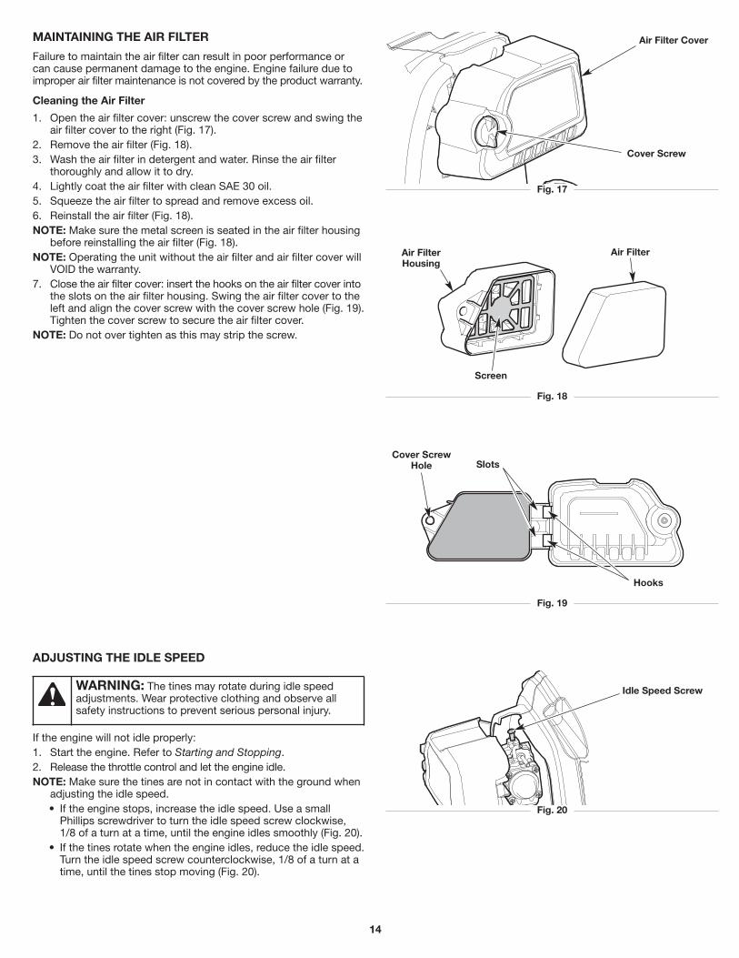
MAINTAINING THE AIR FILTER
Failure to maintain the air filter can result in poor performance or can cause permanent damage to the engine. Engine failure due to improper air filter maintenance is not covered by the product warranty.
Cleaning the Air Filter
1. Open the air filter cover: unscrew the cover screw and swing the air filter cover to the right (Fig. 17).
2. Remove the air filter (Fig. 18). 3. Wash the air filter in detergent and water. Rinse the air filter
thoroughly and allow it to dry. 4. Lightly coat the air filter with clean SAE 30 oil. 5. Squeeze the air filter to spread and remove excess oil. 6. Reinstall the air filter (Fig. 18). NOTE: Make sure the metal screen is seated in the air filter housing
before reinstalling the air filter (Fig. 18). NOTE: Operating the unit without the air filter and air filter cover will
VOID the warranty. 7. Close the air filter cover: insert the hooks on the air filter cover into
the slots on the air filter housing. Swing the air filter cover to the left and align the cover screw with the cover screw hole (Fig. 19). Tighten the cover screw to secure the air filter cover.
NOTE: Do not over tighten as this may strip the screw.
Fig. 20
Idle Speed Screw
ADJUSTING THE IDLE SPEED
If the engine will not idle properly: 1. Start the engine. Refer to Starting and Stopping. 2. Release the throttle control and let the engine idle. NOTE: Make sure the tines are not in contact with the ground when
adjusting the idle speed. • If the engine stops, increase the idle speed. Use a small
Phillips screwdriver to turn the idle speed screw clockwise, 1/8 of a turn at a time, until the engine idles smoothly (Fig. 20).
• If the tines rotate when the engine idles, reduce the idle speed. Turn the idle speed screw counterclockwise, 1/8 of a turn at a time, until the tines stop moving (Fig. 20).
WARNING: The tines may rotate during idle speed adjustments. Wear protective clothing and observe all safety instructions to prevent serious personal injury.
Fig. 17
Air Filter Cover
Cover Screw
Fig. 18
Air FilterAir Filter Housing
Screen
Fig. 19
Hooks
SlotsCover Screw
Hole

15
Fig. 21
0.025 in. (0.635 mm)
CLEANING AND STORAGE
STORAGE
• Never store a fueled unit where fumes may reach an open flame or spark.
• Allow the engine to cool before storing. • Lock up the unit to prevent unauthorized use or damage. • Store the unit in a dry, well-ventilated area. • Store the unit out of the reach of children.
Long-term Storage
1. Remove the fuel cap, tip the unit and drain the fuel into an approved container. Reinstall the fuel cap.
2. Start the engine and allow it to run until it stalls. This ensures that all fuel has been drained from the carburetor.
3. Allow the engine to cool. Remove the spark plug and put 5 drops of any high-quality motor oil into the cylinder. Pull the starter rope slowly to distribute the oil. Reinstall the spark plug.
4. Thoroughly clean the unit and inspect it for any loose or damaged parts. Repair or replace damaged parts and tighten loose screws, nuts or bolts.
Preparing the Unit for Use after Long-term Storage
1. Remove the spark plug. Tip the unit and drain all of the oil from the cylinder into an approved container. Reinstall the spark plug.
2. Change the oil. Refer to Changing the Oil. NOTE: Do not use fuel that has been stored for more than 30 days.
Dispose of old fuel and oil according to federal, state and local regulations.
MAINTAINING THE SPARK PLUG
1. Stop the engine and allow it to cool. Grasp the spark plug boot firmly and pull it from the spark plug.
2. Clean around the spark plug. Remove the spark plug from the cylinder head with a 5/8-inch socket, turning counterclockwise.
3. Inspect the spark plug. If the spark plug is cracked, fouled or dirty, replace it with replacement part #794-00082, a Champion RDZ4H or an equivalent spark plug.
4. Use a feeler gauge to set the air gap at 0.025 in. (0.635 mm) (Fig. 21).
5. Install the spark plug in the cylinder head. Tighten the spark plug with a 5/8-inch socket, turning it clockwise until snug.
NOTE: If using a torque wrench, torque to: 110-120 in.•lb. (12.3-13.5 N•m). Do not over tighten.
6. Reattach the spark plug boot.
WARNING: Do not sand blast, scrape or clean spark plug electrodes. Grit in the engine could damage the cylinder.
CLEANING
Use a small brush to clean the outside of the unit. Do not use strong detergents. Household cleaners that contain aromatic oils such as pine and lemon, and solvents such as kerosene, can damage plastic. Wipe off any moisture with a soft cloth. Clean the tines with a household cleaner to remove gum buildup. Wipe the tines with a light machine oil to prevent rust.
WARNING: To avoid serious personal injury, always stop the engine and allow it to cool before cleaning or maintaining the unit.

16
TROUBLESHOOTING
If further assistance is required, contact an authorized service center.
PROBLEM SOLUTION
The fuel tank is empty Fill the fuel tank with fresh fuel
The primer bulb was not pressed enough Press the primer bulb 10 times
The fuel is old (over 30 days) Drain the fuel tank and add fresh fuel
The spark plug is fouled Replace the spark plug
The engine is hot Refer to the IF... THE ENGINE IS HOT instructions in the Starting and Stopping section
The fuel is old (over 30 days) Drain the fuel tank and add fresh fuel
The tines are bound with dirt or grass Stop the engine, remove the spark plug, and clean the tines
The air filter is dirty Clean or replace the air filter
The air filter is dirty Clean or replace the air filter
The fuel is old (over 30 days) Drain the fuel tank and add fresh fuel
The idle speed is incorrect Adjust the idle speed
The fuel is old (over 30 days) Drain the fuel tank and add fresh fuel
The air filter is dirty Clean or replace the air filter
The spark plug is fouled Replace the spark plug
THE ENGINE WILL NOT START
THE ENGINE WILL NOT IDLE
THE ENGINE WILL NOT ACCELERATE
THE ENGINE LACKS POWER OR STALLS

17
NOTES

18
NOTES

19
WARRANTY
MTD LLC
LIMITED WARRANTY FOR CRAFTSMAN® BRANDED HANDHELD PRODUCT
Limited Warranty
The limited warranty set forth herein is given by MTD LLC to the Initial Purchaser (as defined herein) with respect to new Craftsman branded hand held product (“Product”). This limited warranty does not cover Emission Control Systems and is not a Federal Emission Control Warranty Statement as defined by U.S. federal law. Please refer to the Federal Emission Control Warranty Statement in the operator’s manual for warranties covering Emission Control Systems.
Scope Of The Limited Warranty
MTD LLC offers a limited warranty to the Initial Purchaser for residential or otherwise non-commercial use of the Product: subject to the Exclusions defined herein, during the Warranty Period (defined herein). The “Initial Purchaser” is the first person to purchase the Product from an authorized Craftsman branded product dealer, distributor and/or retailer (each a “Retailer”). Except as otherwise set forth herein, the limited warranty period for this new Product purchased by the Initial Purchaser is two (2) years from the date of purchase as shown on the original sales receipt for the Product (“Warranty Period”).
Defects In Workmanship Or Materials
Subject to the Exclusions, the Product is warranted to be free from manufacturing defects in either workmanship or materials for the Warranty Period. During the Warranty Period, MTD LLC will, at its option, either repair or replace any original part that is covered by this limited warranty and is determined to be defective in workmanship or material.
To Qualify For This Limited Warranty, The Product:
1. Must have been purchased from an authorized Craftsman branded product Retailer. 2. Must have been purchased within the United States by an Initial Purchaser. 3. Must have been used only for residential or otherwise non-commercial purposes. 4. Must have been used in a manner consistent with the normal and proper intended use.
Who Can Perform Repairs Under This Warranty?
In order to qualify for the limited warranty as set forth herein, the repairs made under warranty must be performed by an authorized warranty service provider.
How To Get Service Under This Limited Warranty
To locate an authorized warranty service provider, contact your authorized Retailer or contact www.craftsman.com/warranty or call toll-free 888-331-4569. A COPY OF YOUR SALES RECEIPT IS REQUIRED FOR WARRANTY SERVICE.
What This Limited Warranty Does Not Cover
This Limited Warranty Does Not Cover The Following (the “Exclusions”):
1. Product purchased outside of the United States. 2. Damage due to lack of maintenance and/or improper maintenance as described in the operator’s manual. 3. Normal wear and tear resulting from use of the Product. 4. Use of the Product that is not consistent with the intended use thereof, as described in the operating instructions, including, but not
limited to, abuse, misuse and/or neglect of the Product or any use inconsistent with and/or non-compliant with instructions contained in the operator’s manual.
5. Any expendable, consumable, or routine maintenance item which needs replacement or service as part of normal maintenance, unless such items have defects that cause failure or premature wear within the first thirty (30) days. Where applicable, normal wear items include, but are not limited to, bump knobs, outer spools, cutting line, inner reels, starter pulleys, starter ropes, drive belts, saw chains, guide bars, cultivator tines, filters, spark plugs, carrying cases, scabbards, or blades.
6. Any Product that has been altered or modified in a manner not consistent with the original design of the product or in an unapproved way. 7. Paint repairs or replacements for defective paint (including materials and application) are covered for a period of three (3) months.

20
This Warranty Does Not Cover And MTD LLC Disclaims Any Responsibility For:
1. Loss of time or loss of use of the Product. 2. Transportation costs and other expenses incurred in connection with the transport of the Product to and from the authorized service provider. 3. Any loss or damage to other equipment or personal items. 4. Damage resulting from the installation or use of any accessory or non-OEM (original equipment manufacturer) part for use with the Product.
Limitations:
1. THERE ARE NO IMPLIED WARRANTIES, INCLUDING, BUT NOT LIMITED TO, ANY IMPLIED WARRANTY OF MERCHANTABILITY OR FITNESS FOR A PARTICULAR PURPOSE. NO WARRANTY APPLIES AFTER THE APPLICABLE WARRANTY PERIOD AS SET FORTH ABOVE AS TO THE PARTS AS IDENTIFIED. NO OTHER EXPRESS WARRANTY OR GUARANTY, WHETHER WRITTEN OR ORAL, EXCEPT AS MENTIONED ABOVE, GIVEN BY ANY PERSON OR ENTITY, INCLUDING A DEALER OR RETAILER, WITH RESPECT TO ANY PRODUCT SHALL BIND MTD LLC. DURING THE WARRANTY PERIOD, THE EXCLUSIVE REMEDY IS REPAIR OR REPLACEMENT OF THE DEFECTIVE PART, AS SET FORTH ABOVE. (SOME STATES DO NOT ALLOW LIMITATIONS ON HOW LONG AN IMPLIED WARRANTY LASTS, SO THE ABOVE LIMITATION MAY NOT APPLY TO YOU.)
2. THE PROVISIONS AS SET FORTH HEREIN PROVIDE THE SOLE AND EXCLUSIVE REMEDY ARISING FROM THE SALE. MTD LLC SHALL NOT BE LIABLE FOR INCIDENTAL OR CONSEQUENTIAL LOSS OR DAMAGES INCLUDING, WITHOUT LIMITATION, FOR TRANSPORTATION OR FOR RELATED EXPENSES, OR FOR RENTAL EXPENSES TO TEMPORARILY REPLACE A WARRANTED PRODUCT. (SOME STATES DO NOT ALLOW THE EXCLUSION OR LIMITATION OF INCIDENTAL OR CONSEQUENTIAL DAMAGES, SO THE ABOVE EXCLUSION OR LIMITATION MAY NOT APPLY TO YOU.)
3. In no event shall recovery of any kind be greater than the amount of the purchase price of the Product sold. Alteration of the safety features of the Product shall void this limited warranty. You assume the risk and liability for loss, damage, or injury to you and your property and/or to others and their property arising out of the use or misuse or inability to use the Product.
How State Law Relates To This Warranty.
This limited warranty gives you specific legal rights, and you may also have other rights, which vary from state to state.

21
Toda la información, las ilustraciones y las especificaciones contenidas en este manual se basan en la información más reciente disponible en el momento de impresión del manual. Nos reservamos el derecho de hacer cambios en cualquier momento sin aviso previo. El producto puede variar ligeramente de las ilustraciones contenidas en este manual.
TABLA DE CONTENIDO
Seguridad . . . . . . . . . . . . . . . . . . . . . . . . . . . . . . . . . . . . . . . . . . .21Conozca su unidad . . . . . . . . . . . . . . . . . . . . . . . . . . . . . . . . . . . .25Especificaciones . . . . . . . . . . . . . . . . . . . . . . . . . . . . . . . . . . . . . .25Ensamblaje . . . . . . . . . . . . . . . . . . . . . . . . . . . . . . . . . . . . . . . . . .26Aceite y combustible . . . . . . . . . . . . . . . . . . . . . . . . . . . . . . . . . . .27Arranque y parada . . . . . . . . . . . . . . . . . . . . . . . . . . . . . . . . . . . .29Operación . . . . . . . . . . . . . . . . . . . . . . . . . . . . . . . . . . . . . . . . . . .30Mantenimiento . . . . . . . . . . . . . . . . . . . . . . . . . . . . . . . . . . . . . . .31Limpieza y almacenamiento . . . . . . . . . . . . . . . . . . . . . . . . . . . . .34Solución de problemas . . . . . . . . . . . . . . . . . . . . . . . . . . . . . . . . .35Garantía . . . . . . . . . . . . . . . . . . . . . . . . . . . . . . . . . . . . . . . . . . . . .38Números de servicio . . . . . . . . . . . . . . . . . . . . . . . . .Contraportada
SEGURIDAD
NOTA SOBRE EL AMORTIGUADOR DE CHISPAS
NOTA: Para usuarios de los territorios de bosques de EE. UU. y de los estados de California, Maine, Oregon y Washington. Todos los territorios de bosques de EE. UU. y los estados de California (Códigos de Recursos Públicos 4442 y 4443), Oregon y Washington exigen por ley, que determinados motores de combustión interna que se operan en zonas cubiertas por malezas de bosque y/o hierbas cuenten con un amortiguador de chispas que se deberá mantener en condiciones de uso adecuadas o que el motor se diseñe, equipe y mantenga para prevenir incendios. Corrobore con las autoridades estatales o locales cuáles son las normativas correspondientes a dichas exigencias. El incumplimiento de dichos requerimientos podría generarle una responsabilidad o una multa. La presente unidad se equipa en la fábrica con un amortiguador de chispas. Si requiere reemplazo, póngase en contacto con su representante local de servicio para instalar el conjunto de silenciador adecuado.
Lea el manual del operador y siga todas las advertencias e instrucciones de seguridad. Si no lo hace, el operador y/o los observadores pueden sufrir lesiones graves.
SÍMBOLOS SIGNIFICADO
ADVERTENCIA: Indica un peligro GRAVE. Si no se cumple una ADVERTENCIA de seguridad usted mismo u otras personas PUEDEN sufrir lesiones graves.
PRECAUCIÓN: Indica un peligro de GRAVEDAD MODERADA. Si no se cumple una señal de seguridad de PRECAUCIÓN usted mismo o a otras personas PUEDEN sufrir lesiones o se PUEDEN producir daños materiales.
El objetivo de los símbolos de seguridad es dirigir su atención hacia posibles peligros. Los símbolos de seguridad, así como sus explicaciones, necesitan su atención y comprensión completas. Las advertencias de seguridad no eliminan por sí mismas ningún peligro. Las instrucciones o advertencias que contienen no reemplazan a las medidas adecuadas de prevención de accidentes.
NOTA: Proporciona información o instrucciones de vital importancia para el funcionamiento o el mantenimiento del equipo.
PELIGRO: Indica un peligro EXTREMO. Si no se cumple una advertencia de seguridad de PELIGRO usted mismo u otras personas sufrirán lesiones graves o la muerte.
ADVERTENCIA: Este producto puede exponerlo a productos químicos, incluidos gases de escape del motor, indicados por el estado de California como causantes de cáncer, y monóxido de carbono, indicado por el estado de California como causante de defectos de nacimiento u otros daños reproductivos. Para obtener más información, visite: www.P65Warnings.ca.gov.

22
• INSTRUCCIONES DE SEGURIDAD IMPORTANTES •
LEA TODAS LAS INSTRUCCIONES ANTES DE USAR LA UNIDAD
• Lea las instrucciones con atención. Debe familiarizarse con los controles y con el uso apropiado de la unidad. Sepa cómo detener la unidad y desconectar los controles rápidamente.
• Manténgase alerta. No opere esta unidad si está cansado, enfermo o bajo la influencia de alcohol, drogas o medicamentos.
• Nunca permita a los niños operar la unidad. Los adolescentes deben ser entrenados, acompañados y supervisados por un adulto. Nunca permita a los adultos operar la unidad sin las instrucciones adecuadas.
• Se deben instalar correctamente todos los protectores y accesorios de seguridad antes de operar la unidad.
• Inspeccione la unidad antes de usarla. Verifique si hay piezas dañadas. Compruebe si hay pérdidas de combustible. Compruebe que todas las piezas funcionen correctamente. Compruebe que todas las sujeciones estén en su lugar y bien ajustadas. Compruebe que todas las piezas móviles queden adecuadamente alineadas y no se atasquen. Reemplace las piezas que estén agrietadas, astilladas o dañadas de cualquier manera. Haga reparar o reemplazar por un centro de servicio técnico autorizado todas las piezas que estén dañadas o que no funcionen adecuadamente. No utilice la unidad si hay piezas sueltas o dañadas.
• Tenga en cuenta el riesgo de lesiones en la cabeza, las manos y los pies.
• Inspeccione el área con atención antes de arrancar la unidad. Extraiga las rocas, los vidrios rotos, los clavos, los cables, cordeles y demás objetos que podrían ser arrojados o enredarse en la unidad.
• Despeje la zona de niños, observadores y mascotas; manténgalos fuera de un radio de 50 pies (15 m), como mínimo. Incluso a esa distancia, sigue el riesgo de ser alcanzados por los objetos arrojados por el aire. Sugiérales a los observadores que usen protección ocular. Si alguien se le aproxima, detenga la unidad de inmediato.
• Apriete el control del acelerador y verifique que vuelva automáticamente a la posición de ralentí. Realice todos los ajustes o las reparaciones antes de usar la unidad.
• No cambie la configuración del regulador del motor ni acelere demasiado el motor.
• Esta unidad está diseñada para uso ocasional, para el hogar únicamente.
ADVERTENCIA: Se deben respetar todas las instrucciones de seguridad al usar la unidad. Por favor, lea estas instrucciones antes de utilizar la unidad para garantizar la seguridad del operador y los observadores. Por favor, guarde estas instrucciones para su uso posterior.
DURANTE LA OPERACIÓN
• Utilice anteojos o antiparras de seguridad que cumplan con las normas ANSI / ISEA Z87.1 vigentes y que tengan la identificación correspondiente. Utilice una protección auditiva al operar esta unidad. Utilice una máscara facial o para polvos si la máquina levanta polvo durante su funcionamiento.
• Use pantalones largos y gruesos, botas, guantes y camisa de mangas largas. No use ropa holgada, alhajas, pantalones cortos, sandalias ni ande descalzo. Sujétese el cabello a nivel de los hombros.
• Utilice un calzado especial de protección que mejore la firmeza en superficies resbaladizas.
• Los dientes deben permanecer fijos cuando el motor funciona al ralentí. Si no lo hacen, consulte Ajuste de la velocidad de ralentí.
• Compruebe que los dientes no estén en contacto con nada antes de poner en marcha la unidad.
• Use la unidad solamente con luz de día o con una buena luz artificial. • Evite arranques accidentales. Permanezca en la posición de
arranque siempre que tire de la cuerda de arranque. El operador y la unidad deben estar en una posición estable durante el arranque. Consulte Arranque y Parada.
• Utilice la herramienta apropiada. Use esta herramienta sólo para el propósito para el que fue diseñada. Sólo use la unidad como se indica en este manual.
• Sostenga siempre la unidad con ambas manos durante la operación. Sostenga la manija firmemente.
• No se extienda demasiado. Siempre debe estar bien afirmado y mantener el equilibrio adecuado. Tenga cuidado al trabajar sobre escalinatas, cuestas empinadas o pendientes.
ADVERTENCIAS DE SEGURIDAD PARA LAS UNIDADES A GASOLINA
• Almacene el combustible únicamente en recipientes diseñados específicamente y aprobados para el almacenamiento de dichos materiales.
• Detenga siempre el motor y déjelo enfriar antes de llenar el depósito. Nunca retire la tapa del depósito de combustible ni agregue combustible cuando el motor esté caliente. Afloje siempre lentamente la tapa del depósito de combustible para descargar la presión que haya en el depósito antes de recargar combustible.
• Agregue siempre combustible en una zona al aire libre, limpia y bien ventilada, en la que no haya chispas ni llamas. NO fume.
• Nunca opere la unidad si la tapa del combustible no está bien sujeta en su lugar.
• Evite que se genere una fuente de encendido para el combustible derramado. Limpie de inmediato el combustible derramado de la unidad, antes de encenderla. Mueva la unidad al menos 30 pies (9.1m) de la fuente de combustible y del sitio antes de arrancar el motor. NO fume.
• Nunca arranque ni use la unidad dentro de una habitación o de una construcción cerrada. La inhalación de humos de escape puede ser mortal. Opere esta unidad únicamente en una zona bien ventilada, al aire libre.
ADVERTENCIA: La gasolina es sumamente inflamable y sus vapores pueden explotar si se encienden. Adopte las siguientes precauciones:

23
• Adopte extrema precaución cuando vaya marcha atrás o cuando jale de la máquina hacia usted.
• Mantenga las manos, el rostro y los pies alejados de todas las piezas móviles. No toque ni intente detener las piezas móviles.
• No toque el motor, el alojamiento del engranaje ni el silenciador. Estas partes se ponen extremadamente calientes por el funcionamiento, incluso después de que se apaga la unidad.
• No opere la unidad a una velocidad mayor a la necesaria para la tarea. No haga funcionar la unidad a alta velocidad cuando no está en uso.
• No exija demasiado a la unidad. Si se usa a la velocidad para la que fue diseñada, realizará un trabajo más eficiente y seguro.
• Detenga siempre la unidad cuando la operación esté demorada o cuando la mueva de un lugar a otro. Compruebe que todas las piezas móviles se detengan completamente.
• Si la unidad golpea o se engancha en un objeto extraño, detenga la unidad inmediatamente. Verifique si está dañada. Si hay daño, no vuelva a arrancar o hacer funcionar la unidad hasta hacerlo arreglar. No utilice la unidad si hay piezas sueltas o dañadas.
• Apague el motor y desconecte la bujía para realizar tareas de mantenimiento o reparación.
• Use sólo piezas de reemplazo y accesorios del fabricante del equipo original (OEM) para esta unidad. Los puede adquirir al distribuidor de servicio autorizado. Si usa cualquier otra pieza o accesorio, el usuario podría lesionarse gravemente o la unidad podría dañarse y se anularía la garantía.
• Mantenga limpia la unidad. Quite con cuidado cualquier resto de vegetación u otros residuos que puedan bloquear las piezas móviles.
• A fin de reducir el riesgo de incendio, reemplace el silenciador y el amortiguador de chispas si están averiados. Mantenga el motor y el silenciador libres de hierbas, hojas y de la acumulación excesiva de grasa o de carbono.
• Si la unidad comienza a vibrar en forma anormal, deténgala de inmediato. Inspeccione la unidad para determinar la causa de la vibración. La vibración por lo general indica que hay algún problema.
• Sea precavido cuando cultive en terreno sólido. Los dientes pueden clavarse en la tierra y propulsar la unidad hacia delante. Si esto ocurre, libere la(s) barra(s) de control y no retenga la unidad.
OTRAS ADVERTENCIAS DE SEGURIDAD
• El mantenimiento de la unidad debe ser minucioso. Siga todas las instrucciones de mantenimiento de este manual.
• No realice ningún procedimiento de mantenimiento que no figure en este manual. Todas las tareas de reparación, con excepción de los procedimientos de mantenimiento que se describen en este manual, deben ser realizados por un distribuidor de servicio autorizado.
• Nunca extraiga, modifique o deje inoperativo ningún dispositivo de seguridad que venga con la unidad.
• Antes de inspeccionar, mantener, limpiar, guardar, transportar o reemplazar alguna de las piezas en la unidad: 1. Detenga la unidad. Consulte Arranque y Parada. 2. Asegúrese de que se hayan detenido todas las piezas móviles. 3. Deje que la unidad se enfríe. 4. Desconecte el cable de la bujía.
• Sujete la unidad durante el transporte. • Nunca almacene la unidad con combustible en el depósito, en el
interior de una construcción donde las emanaciones puedan alcanzar una llama abierta (luces piloto, etc.) o chispas (interruptores, motores eléctricos, etc.).
• Almacene la unidad en un lugar seco, asegurada o a una altura que evite que se la use sin autorización o se la dañe. Mantenga la unidad lejos del alcance de los niños.
• Nunca rocíe ni arroje chorros de agua ni de ningún otro líquido a la unidad. Mantenga las manijas secas y limpias (sin residuos, aceite ni grasa). Limpie la unidad luego de cada uso. Consulte Limpieza y almacenamiento. No utilice solventes o detergentes fuertes.
• Limpie los dientes con agua. Lubrique los dientes con aceite para máquinas a fin de evitar la oxidación.
• Guarde estas instrucciones. Consúltelas con frecuencia y úselas para capacitar a otros usuarios. Si le presta esta unidad a otras personas, también debe prestarles estas instrucciones.
GUARDE ESTAS INSTRUCCIONES

24
• SÍMBOLOS INTERNACIONALES Y DE SEGURIDAD • Este manual del operador describe símbolos de seguridad e internacionales, así como pictogramas, que pueden aparecer en este producto. Lea el manual del operador para obtener información completa sobre seguridad, montaje, funcionamiento, mantenimiento y reparaciones.
SÍMBOLOS SIGNIFICADO SÍMBOLOS SIGNIFICADO
• SÍMBOLO DE ALERTA DE SEGURIDAD
Indica peligro, advertencia o precaución. Puede utilizarse junto con otros símbolos o pictogramas.
• LEA EL MANUAL DEL OPERADOR
ADVERTENCIA : Lea el (los) manual(es) del operador y cumpla todas las advertencias e instrucciones de seguridad. Si no lo hace, el operador y/o los observadores pueden sufrir lesiones graves.
• UTILICE PROTECCIÓN OCULAR Y AUDITIVA
ADVERTENCIA: Los objetos que son arrojados por el aire y los ruidos fuertes pueden provocar graves lesiones oculares y pérdidas de audición. Cuando opere esta unidad, utilice protección ocular que cumpla con las normas ANSI / ISEA Z87.1 vigentes y protectores auditivos. Utilice una máscara que cubra todo el rostro si es necesario.
• UTILICE PROTECCIÓN DE PIES
Siempre utilice calzado reforzado, antideslizante, cuando haga funcionar esta unidad.
• UTILICE PROTECCIÓN DE MANOS
Siempre utilice guantes reforzados, antideslizantes, cuando manipule esta unidad.
• COMBUSTIBLE SIN PLOMO
Utilice siempre combustible limpio, nuevo y sin plomo.
• ACEITE
Consulte el manual del operador para conocer el tipo adecuado de aceite.
• NO UTILICE COMBUSTIBLE E85 EN ESTA UNIDAD
PRECAUCIÓN: Se ha demostrado que el combustible que contiene más de un 10% de etanol es probable que dañe este motor y anule la garantía.
• APAGADO/ENCENDIDO DE CONTROL DE PARADA
ENCENDIDO / ARRANQUE / MARCHA
• APAGADO/ENCENDIDO DE CONTROL DE PARADA
APAGADO o PARADA
• BULBO DEL CEBADOR
Presione por completo el bulbo del cebador lentamente 10 veces.
• LOS OBJETOS ARROJADOS PUEDEN PROVOCAR LESIONES GRAVES
ADVERTENCIA: Es posible que se arrojen objetos pequeños por el aire a alta velocidad, lo cual puede provocar lesiones.
• MANTENGA ALEJADOS A LOS OBSERVADORES
ADVERTENCIA: Mantenga a todos los observadores, especialmente a los niños y las mascotas, al menos a 50 pies (15 m) de la zona de trabajo.
• SUPERFICIE CALIENTE
ADVERTENCIA: No toque el motor, el alojamiento del engranaje ni el silenciador cuando estén calientes. Puede quemarse. Estas piezas se calientan extremadamente durante el funcionamiento. Una vez apagadas, continúan calientes durante un período breve.
• LOS DIENTES GIRATORIOS DE LAS CULTIVADORAS PARA JARDÍN PUEDEN PROVOCAR LESIONES GRAVES
ADVERTENCIA: Pare el motor y espere a que los dientes dejen de moverse antes de instalar o retirar dientes, o antes de realizar tareas de limpieza o mantenimiento. Mantenga las manos y los pies alejados de los dientes giratorios.
• NO SE PARE Mantenga siempre una posición y equilibrio adecuados. No se estire demasiado, tenga mucho cuidado cuando trabaje en declives y pendientes empinadas.
• COLOQUE EL PIE DERECHO AQUÍ
Evite arranques accidentales. Permanezca en la posición de arranque siempre que tire de la cuerda de arranque. El operador y la unidad deben estar en una posición estable durante el arranque.

Bombilla del cebador
Cubierta del filtro de aire
Ensamblaje de la rueda
Dientes
Caja de engranajes
Protector de dientes
Manija de la cuerda de arranque
Silenciador
Bujía de encendido
Tapa del combustible
Manubrio
Control del regulador
Interruptor encendido /
apagado
Tapón para llenado de aceite
Perillas
25
CONOZCA SU UNIDAD
APLICACIONES
• Use esta unidad para cultivar tierra herbosa y tierra negra ligera a mediana.
• También se utiliza para cultivar áreas de jardines, alrededor de árboles, etc.
Tipo de motor . . . . . . . . . . . . . . . . . . . . . . . . . . . . . . . . . . . . . . . . . . . . . . . . . . . . . . . . . . . . . . . . . . . . . . . . . Refrigerado por aire, de 4 tiempos Desplazamiento . . . . . . . . . . . . . . . . . . . . . . . . . . . . . . . . . . . . . . . . . . . . . . . . . . . . . . . . . . . . . . . . . . . . . . . . . . . 30 cc (1.83 pulgadas cúbicas) Separación de la bujía de encendido . . . . . . . . . . . . . . . . . . . . . . . . . . . . . . . . . . . . . . . . . . . . . . . . . . . . . . . . . . . . . . . . 0.635 mm (0.025 pulg.) Bujía de encendido. . . . . . . . . . . . . . . . . . . . . . . . . . . . . . . . . . . . . . . . . . . . . . . . . . . . . . . . . . . . . . . . . . Champion® RDZ4H o bujía equivalente Lubricación . . . . . . . . . . . . . . . . . . . . . . . . . . . . . . . . . . . . . . . . . . . . . . . . . . . . . . . . . . . . . . . . . . . . . . . . . . . . . . . . . . . . . . . . . . . . Aceite SAE 30 Capacidad de aceite del cárter . . . . . . . . . . . . . . . . . . . . . . . . . . . . . . . . . . . . . . . . . . . . . . . . . . . . . . . . . . . . . . . . . . . . . . . . . 3.04 onzas (90 ml) Capacidad del depósito de combustible . . . . . . . . . . . . . . . . . . . . . . . . . . . . . . . . . . . . . . . . . . . . . . . . . . . . . . . . . . . . . . . . . . 15 onzas (444 ml) Ancho de la trayectoria de cultivo (Máximo) . . . . . . . . . . . . . . . . . . . . . . . . . . . . . . . . . . . . . . . . . . . . . . . . . . . . . . . . . . . . 12 pulgadas (30.5 cm) Profundidad de cultivo (Máximo) . . . . . . . . . . . . . . . . . . . . . . . . . . . . . . . . . . . . . . . . . . . . . . . . . . . . . . . . . . . . . . . . . . . . . . 6 pulgadas (15.2 cm) Peso aproximado de la unidad (sin combustible) . . . . . . . . . . . . . . . . . . . . . . . . . . . . . . . . . . . . . . . . . . . . . . . . . . . 30 - 31 libras (13.6 - 14.1 kg)
ESPECIFICACIONES*
* Todas las especificaciones están basadas se basan en la información más reciente sobre el producto disponible al momento de la impresión. Nos reservamos el derecho a realizar cambios en cualquier momento sin previo aviso.
NO SE REQUIERE DE HERRAMIENTAS PARA EL ENSAMBLAJE

26
ENSAMBLAJE
Fig. 2
Pasador de chaveta
Fig. 1
Conjunto de la rueda
Guía de la rueda
Pasador de horquilla
INSTALACIÓN Y AJUSTE DEL CONJUNTO DE LA RUEDA
Instalación del conjunto de la rueda
1. Inserte el conjunto de la rueda en el soporte de la rueda. La forma en "J" del conjunto de la rueda debe quedar orientada en sentido contrario a la unidad (Fig. 1).
2. El orificio del soporte de la rueda debe quedar alineado con el orificio deseado del conjunto de la rueda (Fig. 1).
3. Inserte el pasador de horquilla a través de los orificios alineados (Fig. 2).
4. Inserte el pasador de chaveta en el pasador de horquilla (Fig. 2). NOTA: Puede ser necesario ajustar la posición del conjunto de la
rueda antes de utilizar la unidad.
Ajuste del conjunto de la rueda
1. Extraiga el pasador de chaveta del pasador de horquilla (Fig. 2). 2. Extraiga el pasador de horquilla del soporte de la rueda y del
conjunto de la rueda (Fig. 2). 3. El orificio del soporte de la rueda debe quedar alineado con el
orificio deseado del conjunto de la rueda (Fig. 1). NOTA: Si se mueve el conjunto de la rueda hacia abajo, se eleva la
altura de la rueda. Si se mueve el conjunto de la rueda hacia arriba, se baja la altura de la rueda.
4. Inserte el pasador de horquilla a través de los orificios alineados (Fig. 2).
5. Inserte el pasador de chaveta en el pasador de horquilla (Fig. 2).
ADVERTENCIA: A fin de evitar lesiones personales graves, las ruedas deben estar colocadas cuando se utilice la unidad.
ADVERTENCIA: A fin de evitar lesionarse con los dientes, utilice guantes gruesos y camisa de mangas largas al instalar las ruedas.
Bajar
Subir
Fig. 3
POSICIONAMIENTO DE LA BARRA DE CONTROL
1. Coloque la unidad en posición vertical. 2. Afloje las perillas (Fig. 4). 3. Gire la barra de control a la posición operativa (Fig. 3). NOTA: Se debe ser precavido para evitar apretar los cables cuando
se ubican las barras de control (Fig. 4). 4. Ajuste bien las perillas. NOTA: No ajuste las perillas demasiado. 5. Reajuste los cables para que queden parejos y ajustados contra
la barra de control.
Perillas
Fig. 4
Perillas
Cables
27
ACEITE Y COMBUSTIBLE
Fig. 5
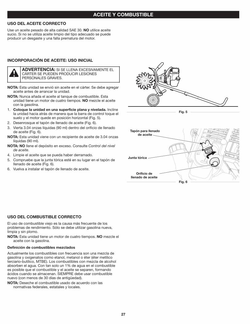
USO DEL ACEITE CORRECTO
Use un aceite pesado de alta calidad SAE 30. NO utilice aceite sucio. Si no se utiliza aceite limpio del tipo adecuado se puede producir un desgaste y una falla prematura del motor.
Fig. 6
Tapón para llenado de aceite
Orificio de llenado de aceite
Junta tórica
USO DEL COMBUSTIBLE CORRECTO
El uso de combustible viejo es la causa más frecuente de los problemas de rendimiento. Sólo se debe utilizar gasolina nueva, limpia y sin plomo. NOTA: Esta unidad tiene un motor de cuatro tiempos. NO mezcle el
aceite con la gasolina.
Definición de combustibles mezclados
Actualmente los combustibles con frecuencia son una mezcla de gasolina y oxigenatos como etanol, metanol o éter (éter metílico terciario-butílico, MTBE). Los combustibles con mezcla de alcohol absorben el agua. Con tan solo un 1% de agua en el combustible es posible que el combustible y el aceite se separen, formando ácidos cuando se almacenan. SIEMPRE debe usar combustible nuevo (con menos de 30 días de antigüedad). NOTA: Deseche el combustible usado de acuerdo con las
normativas federales, estatales y locales.
INCORPORACIÓN DE ACEITE: USO INICIAL
NOTA: Esta unidad se envió sin aceite en el cárter. Se debe agregar aceite antes de arrancar la unidad.
NOTA: Nunca añada el aceite al tanque de combustible. Esta unidad tiene un motor de cuatro tiempos. NO mezcle el aceite con la gasolina.
1. Coloque la unidad en una superficie plana y nivelada. Incline la unidad hacia atrás de manera que la barra de control toque el suelo y el motor quede en posición horizontal (Fig. 5).
2. Desenrosque el tapón de llenado de aceite (Fig. 6). 3. Vierta 3.04 onzas líquidas (90 ml) dentro del orificio de llenado
de aceite (Fig. 6). NOTA: Esta unidad viene con un recipiente de aceite de 3.04 onzas
líquidas (90 ml). NOTA: NO llene el depósito en exceso. Consulte Control del nivel
de aceite. 4. Limpie el aceite que se pueda haber derramado. 5. Compruebe que la junta tórica esté en su lugar en el tapón de
llenado de aceite (Fig. 6). 6. Vuelva a instalar el tapón de llenado de aceite.
ADVERTENCIA: SI SE LLENA EXCESIVAMENTE EL CÁRTER SE PUEDEN PRODUCIR LESIONES PERSONALES GRAVES.

28
CARGA DE COMBUSTIBLE EN LA UNIDAD
1. Ubique la unidad con la tapa del combustible orientada hacia arriba. 2. Extraiga lentamente la tapa de combustible. 3. Ubique el pico del recipiente de combustible dentro del orificio
de llenado del depósito de combustible y llene el depósito. NOTA: No llene en exceso el depósito de combustible. 4. Limpie el combustible que se pueda haber derramado. 5. Vuelva a colocar la tapa del combustible. 6. Mueva la unidad al menos 30 pies (9.1m) del recipiente de
combustible y del sitio de carga de combustible antes de arrancar el motor.
ADVERTENCIA: La gasolina es extremadamente inflamable. Los vapores encendidos pueden explotar. Detenga siempre el motor y déjelo enfriar antes de llenar el depósito de combustible. No fume mientras llena el depósito. Mantenga las chispas y llamas abiertas a una distancia de la zona.
ADVERTENCIA: Retire la tapa del combustible lentamente a fin de evitar lesiones ocasionadas por salpicaduras de combustible. Nunca opere la unidad si la tapa del combustible no está bien sujeta en su lugar.
ADVERTENCIA: Agregue combustible en una zona al aire libre, limpia y bien ventilada. Limpie de inmediato la gasolina que se haya derramado. Evite que se genere una fuente de encendido para el combustible derramado. No arranque el motor hasta que se hayan disipado los vapores del combustible.
Uso de combustibles mezclados
Si utiliza un combustible mezclado: • Utilice siempre gasolina nueva sin plomo • Use el aditivo para combustible STA-BIL® u otro equivalente
Uso de aditivos para el combustible
Utilice un aditivo para el combustible, como el estabilizador de combustible STA-BIL u otro equivalente, para inhibir la corrosión y minimizar los depósitos de goma. Agregue 0.8 onzas (23 ml) de aditivo para combustible por galón de combustible según las instrucciones del recipiente. NUNCA agregue aditivos para el combustible directamente al depósito de combustible de la unidad.
PRECAUCIÓN: NO UTILICE COMBUSTIBLE E85 EN ESTA UNIDAD. Se ha demostrado que el combustible que contiene más de un 10% de etanol es probable que dañe este motor y anule la garantía.

29
ADVERTENCIA: Los dientes pueden girar durante el proceso de arranque. Siempre párese en la posición de arranque. Utilice un pie para mantener las ruedas en su lugar. Incline la unidad ligeramente hacia atrás para separar los dientes del suelo (Fig. 9).
ADVERTENCIA: Opere esta unidad únicamente en una zona bien ventilada, al aire libre. Los humos de escape de monóxido de carbono pueden ser mortales en un lugar cerrado.
ADVERTENCIA: Se debe evitar arrancar accidentalmente la unidad. A fin de evitar que se produzcan lesiones graves, el operador y la unidad deben estar en una posición estable cuando se jala la cuerda de arranque (Fig. 9).
ARRANQUE Y PARADA
INSTRUCCIONES DE ARRANQUE
NOTA: No hay necesidad de encender la unidad. El interruptor de Encendido/Apagado debe estar en la posición Encendido ( I ) en todo momento (Fig. 7).
Antes de hacer arrancar la unidad 1. Controle el nivel de aceite. Consulte Control del nivel de aceite. 2. Cargue el depósito de combustible. Consulte Carga de
combustible en la unidad.
Arranque de la unidad
1. Presione y luego suelte el bulbo del cebador lentamente 10 veces (Fig. 8).
2. Párese en la posición de arranque (Fig. 9). Sujete firmemente la barra de control con una mano. Sostenga la cuerda de arranque con la otra mano. Use el pie para aguantar las ruedas.
3. Incline la unidad ligeramente hacia atrás para separar los dientes del suelo (Fig. 9).
4. Apriete y mantenga oprimido el control del acelerador (Fig. 7). 5. Siga sosteniendo oprimido el control del acelerador. Tire de la
cuerda de arranque con un movimiento controlado y firme hasta que arranque la unidad (Fig. 9).
SI... el motor no arranca luego de tirar de la cuerda del arranque 10 veces, repita el procedimiento de arranque.
SI... el motor no arranca después de 3 intentos, comience el procedimiento de arranque con el paso 2.
SI... el motor se detiene al presionar el control del acelerador, repita el procedimiento de arranque.
SI EL MOTOR ESTÁ CALIENTE... repita el procedimiento de arranque.
Fig. 7
Control del acelerador
Interruptor encendido / apagado
I = Encendido
O = Apagado
Fig. 9
Posición que empieza
Manija de la cuerda de arranque
Fig. 8
Bulbo del cebador
INSTRUCCIONES DE PARADA
1. Suelte el control del acelerador y deje que el motor funcione en ralentí.
2. Oprima y mantenga apretado el interruptor de encendido/apagado en la posición Apagado (O) hasta que el motor se pare por completo (Fig. 7).

30
CONSEJOS PARA LA OPERACION
1. Transporte el cultivador hacia el área de trabajo antes de arrancar el motor. Consulte Mover la unidad.
2. Arranque la unidad siguiendo las Instrucciones de arranque. 3. Incline la unidad hacia atrás hasta que las púas desmalezan la tierra. 4. Sin apoyar los dientes en el suelo, apriete el control del
regulador para aumentar la velocidad del motor. 5. Sujete firmemente el manubrio con ambas manos y baje
lentamente la unidad hasta que los dientes se pongan en contacto con el terreno (Fig. 10).
6. A medida que comienza la actividad de cultivo, mueva el cultivador hacia atrás de modo que las púas puedan penetrar en la tierra.
7. Una vez que se ha abierto la tierra, continúe a un ritmo moderado hasta que conozca bien los controles y el manejo del cultivador.
8. Mueva el cultivador hacia atrás para mejorar la profundidad de cultivo y reducir su esfuerzo.
9. Si las púas están cavando a una profundidad excesiva o insuficiente, ajuste las púas de acuerdo a la sección Ajuste de la profundidad de las púas.
AJUSTE DE LA PROFUNDIDAD
Los dientes deberían entrar de 4 a 5 pulgadas en la mayoría de los suelos de jardín. De ser necesario, ajuste los dientes como sigue: 1. Apague el motor y espere que se enfríe. Tome el alambre de la
bujía con firmeza y sáquelo de la bujía de encendido. 2. Para que los dientes entren a menos profundidad, suba la altura
de la rueda, de lo contrario, baje la altura de la rueda. Remítase a Ajustar el ensamblaje de la rueda en la sección Instrucciones de ensamblaje.
3. Vuelva a conectar el cable de la bujía de encendido y continúe su uso.
MOVER LA UNIDAD
1. Apague el motor. 2. Incline la unidad hacia atrás hasta que las púas desmalezan la tierra. 3. Empuje o lleve la unidad hasta el próximo lugar que deba cultivar.
OPERACIÓN
ADVERTENCIA: Vista en forma adecuada para reducir el riesgo de lesiones cuando opere esta unidad. No use ropa holgada ni alhajas. Use protección ocular y auditiva. Use pantalones largos y gruesos, botas y guantes. No use pantalones cortos, sandalias ni trabaje descalzo.
ADVERTENCIA: Para evitar graves lesiones personales, nunca levante ni transporte la unidad con el motor en marcha.
ADVERTENCIA: Para evitar lesiones personales graves, apague siempre el motor cuando la operación se demore o al mover la unidad de un lugar a otro.
ADVERTENCIA: Para evitar graves lesiones personales, tenga mucho cuidado cuando invierta o gire la unidad hacia usted.
Fig. 10
Posición de funcionamiento

31
MANTENIMIENTO
ADVERTENCIA: A fin de evitar lesiones personales graves, siempre pare el motor y deje que se enfríe antes de limpiar o mantener la unidad. No realice ninguna tarea de limpieza o mantenimiento mientras la unidad esté en funcionamiento. Desconecte el cable de la bujía para evitar que la unidad arranque accidentalmente.
ADVERTENCIA: Utilice vestimenta de protección y respete todas las instrucciones de seguridad para evitar que se produzcan lesiones personales graves.
PLAN DE MANTENIMIENTO
Lleve a cabo los procedimientos necesarios de mantenimiento con la frecuencia indicada en la tabla. Estos procedimientos deberán también formar parte de cualquier ajuste de temporada. NOTA: Es posible que algunos procedimientos de mantenimiento
requieran herramientas o habilidades especiales. Si no está seguro acerca de estos procedimientos, lleve la unidad a un distribuidor de servicio autorizado. Para más información, llame al 1-888-331-4569.
NOTA: Los trabajos de mantenimiento, reemplazo o reparación de los dispositivos y los sistemas de control de emisiones puede realizarlos un distribuidor de servicio autorizado. Para más información, llame al 1-888-331-4569.
NOTA: Para ver la lista completa de términos y la cobertura de los dispositivos de control de emisiones como parachispas, silenciador, carburador, etc., lea la declaración de California/ EPA que viene junto con la unidad.
FRECUENCIA MANTENIMIENTO REQUERIDACada 10 horas • Limpie y vuelva a lubricar el filtro de aire.
Consulte Mantenimiento del filtro de aire.
Después de las primeras 10 horas y a las 38 horas
• Cambie el aceite. Consulte Cambio de aceite. • Solicite a un distribuidor de servicio que
controle la holgura del balancín. • Controle el estado y la separación de la
bujía de encendido. Consulte Mantenimiento de la bujía de encendido.
Fig. 11
Pasador de horquilla
Pasador de chaveta
REEMPLAZO DE LOS DIENTES
Se deben reemplazar todos los dientes al mismo tiempo porque se desgastan de manera uniforme por el uso normal. Trabaje de un lado por vez.
Preparación de la unidad para la extracción de los dientes
1. Detenga el motor y deje que se enfríe. Sujete con firmeza el cable de la bujía y tire del capuchón para sacarlo de la bujía.
2. Coloque la unidad en una superficie plana y nivelada. Incline la unidad hacia atrás de manera que la barra de control toque el suelo y el motor quede en posición horizontal (Fig. 13).
NOTA: Puede ser necesario lavar la suciedad de los dientes y de los ejes de los dientes antes de extraerlos.
Extracción de los dientes viejos
1. Extraiga el pasador de chaveta del pasador de horquilla (Fig. 11). Extraiga el pasador de horquilla de los dientes dobles y del eje de los dientes.
2. Deslice los dientes fuera de su eje. 3. Repita este proceso para el otro lado.
Instalación de los dientes nuevos
1. Limpie y lubrique el eje de los dientes. 2. Deslice los dientes nuevos sobre el eje de los dientes. Los bujes
deben quedar enfrentados entre sí (Fig. 12). Instale el diente único primero. Luego instale los dientes dobles. Se debe alinear el orificio de los dientes dobles con el orificio del eje de los dientes (Fig. 12).
3. Inserte un pasador de horquilla a través de los orificios alineados (Fig. 11). Inserte un pasador de chaveta en el pasador de horquilla.
4. Repita este proceso para el otro lado. 5. Vuelva a conectar el cable de la bujía.
ADVERTENCIA: A fin de evitar lesiones personales graves, utilice siempre guantes gruesos al manipular los dientes.
Vista frontal
Fig. 12
Diente único
Dientes dobles
Eje de los dientes
Bujes
OrificiosVista frontal

32
Fig. 13
Fig. 14
Tapón para llenado de aceite
Orificio de llenado de aceite
Junta tórica
Fig. 15
Rosca inferior
Orificio de llenado de
aceite
Nivel máximo de aceite
Fig. 16
CAMBIO DE ACEITE
Cambie el aceite mientras el motor aún está caliente. El aceite fluirá libremente y arrastrará más impurezas. 1. Limpie la zona que rodea el tapón de llenado de aceite (Fig. 14) a
fin de evitar que ingresen residuos en el orificio de carga de aceite.
2. Desenrosque el tapón de llenado de aceite. 3. Incline la unidad verticalmente para verter el aceite fuera del
orificio de llenado de aceite y al interior del recipiente (Fig. 16). Deje bastante tiempo para que se drene completamente.
NOTA: Deseche el aceite viejo de acuerdo con las normativas federales, estatales y locales.
4. Limpie el aceite que se pueda haber derramado. 5. Vierta 3.04 onzas líquidas (90 ml) de aceite SAE 30 dentro del
orificio de llenado de aceite. NOTA: NO llene el depósito en exceso. Consulte Control del nivel
de aceite. 6. Limpie el aceite que se pueda haber derramado. 7. Compruebe que la junta tórica esté en su lugar en el tapón de
llenado de aceite (Fig. 14). 8. Vuelva a instalar el tapón de llenado de aceite.
CONTROL DEL NIVEL DE ACEITE
1. Detenga el motor y deje que se enfríe. 2. Ubique la unidad sobre una superficie plana y nivelada.
Incline la unidad hacia atrás de manera que la barra de control toque el suelo y el motor quede en posición horizontal (Fig. 13).
NOTA: Si no se mantiene el nivel del motor puede resultar en exceso de aceite.
3. Limpie la zona que rodea el tapón de llenado de aceite (Fig. 14) a fin de evitar que ingresen residuos en el orificio de carga de aceite (Fig. 14).
4. Desenrosque el tapón de llenado de aceite. 5. Observe el interior del orificio de llenado de aceite; use una
linterna si es necesario. El nivel de aceite sólo debe tocar la rosca inferior del orificio de llenado de aceite (Fig. 15). • Si el nivel de aceite es demasiado bajo, agregue una pequeña
cantidad de aceite en el orificio de llenado de aceite hasta que el aceite esté en el nivel correcto.
• Si el nivel de aceite es demasiado alto, incline la unidad y drene el exceso de aceite en un recipiente adecuado (Fig. 16).
6. Limpie el aceite que se pueda haber derramado. 7. Compruebe que la junta tórica esté en su lugar en el tapón de
llenado de aceite (Fig. 14). 8. Vuelva a instalar el tapón de llenado de aceite.
ADVERTENCIA: Controle el nivel de aceite antes de cada uso. No está de más insistir en la importancia de mantener el nivel de aceite adecuado.
ADVERTENCIA: NO llene en exceso el cárter. SI SE LLENA EXCESIVAMENTE EL CÁRTER SE PUEDEN PRODUCIR LESIONES PERSONALES GRAVES.
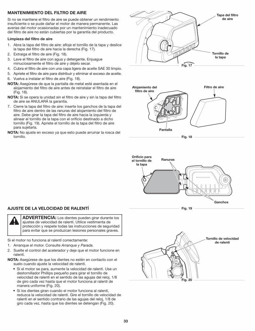
33
MANTENIMIENTO DEL FILTRO DE AIRE
Si no se mantiene el filtro de aire se puede obtener un rendimiento insuficiente o se pude dañar el motor de manera permanente. Las averías del motor ocasionadas por un mantenimiento inadecuado del filtro de aire no están cubiertas por la garantía del producto.
Limpieza del filtro de aire
1. Abra la tapa del filtro de aire: afloje el tornillo de la tapa y deslice la tapa del filtro de aire hacia la derecha (Fig. 17).
2. Extraiga el filtro de aire (Fig. 18). 3. Lave el filtro de aire con agua y detergente. Enjuague
minuciosamente el filtro de aire y déjelo secar. 4. Cubra el filtro de aire con una capa ligera de aceite SAE 30 limpio. 5. Apriete el filtro de aire para distribuir y eliminar el exceso de aceite. 6. Vuelva a instalar el filtro de aire (Fig. 18). NOTA: Asegúrese de que la pantalla de metal esté asentada en el
alojamiento del filtro de aire antes de reinstalar el filtro de aire (Fig. 18).
NOTA: Si se opera la unidad sin el filtro de aire y sin la tapa del filtro de aire se ANULARÁ la garantía.
7. Cierre la tapa del filtro de aire: inserte los ganchos de la tapa del filtro de aire dentro de las ranuras del alojamiento del filtro de aire. Debe girar la tapa del filtro de aire hacia la izquierda y alinear el tornillo de la tapa con el orificio destinado a dicho tornillo (Fig. 19). Apriete el tornillo de la tapa del filtro de aire para sujetarla.
NOTA: No ajuste en exceso ya que esto puede arruinar la rosca del tornillo.
Fig. 19
Fig. 17
Tapa del filtro de aire
Tornillo de la tapa
Ganchos
RanurasOrificio para el tornillo de
la tapa
Fig. 20
Tornillo de velocidad de ralentí
AJUSTE DE LA VELOCIDAD DE RALENTÍ
Si el motor no funciona al ralentí correctamente: 1. Arranque el motor. Consulte Arranque y Parada. 2. Suelte el control del acelerador y deje que el motor funcione en
ralentí. NOTA: Asegúrese de que los dientes no estén en contacto con el
suelo cuando ajuste la velocidad de ralentí. • Si el motor se para, aumente la velocidad de ralentí. Use un
destornillador Phillips pequeño para girar el tornillo de velocidad de ralentí en el sentido de las agujas del reloj, 1/8 de giro cada vez hasta que el motor funciona al ralentí de manera uniforme (Fig. 20).
• Si los dientes giran cuando el motor funciona al ralentí, reduzca la velocidad de ralentí. Gire el tornillo de velocidad de ralentí en el sentido contrario de las agujas del reloj, 1/8 de giro cada vez, hasta que los dientes se detengan (Fig. 20).
ADVERTENCIA: Los dientes pueden girar durante los ajustes de velocidad de ralentí. Utilice vestimenta de protección y respete todas las instrucciones de seguridad para evitar que se produzcan lesiones personales graves.
Fig. 18
Filtro de aireAlojamiento del filtro de aire
Pantalla

34
Fig. 21
0.025 pulgadas (0.635 mm)
LIMPIEZA Y ALMACENAMIENTO
MANTENIMIENTO DE LA BUJÍA
1. Detenga el motor y deje que se enfríe. Sujete con firmeza la funda de la bujía y tire para sacarla de la bujía.
2. Limpie alrededor de la bujía. Retire la bujía de la tapa del cilindro con una llave de cubo de 5/8 pulgadas, girando en sentido contrario a las agujas del reloj.
3. Inspeccione la bujía. Si la bujía está agrietada, averiada o sucia, reemplácela por una pieza de reemplazo n.° 794-00082, una Champion RDZ4H o una bujía equivalente.
4. Use un calibrador de separación para ajustar una separación de aire de 0.025 pulgadas (0.635 mm) (Fig. 21).
5. Instale la bujía dentro de la tapa del cilindro. Apriete la bujía con una llave de cubo de 5/8 pulgadas, girando en el sentido de las agujas del reloj hasta que quede ajustada.
NOTA: Si se usa una llave de par, apriete hasta: 110-120 pulgada•libra (12.3-13.5 N•m). No ajuste demasiado.
6. Vuelva a colocar la funda de la bujía.
ADVERTENCIA: No limpie de forma abrasiva ni raspe o limpie los electrodos de las bujías. La presencia de polvo abrasivo en el motor podría dañar el cilindro.
LIMPIEZA
Use un cepillo pequeño para limpiar el exterior de la unidad. No utilice detergentes fuertes. Los productos de limpieza para el hogar que contienen aceites aromáticos como pino y limón, y los disolventes como el queroseno, pueden dañar el plástico. Limpie todo rastro de humedad con una tela suave. Limpie los dientes con un limpiador doméstico para retirar los residuos gomosos acumulados. Limpie los dientes con una capa delgada de aceite para máquinas a fin de evitar la oxidación.
ADVERTENCIA: A fin de evitar lesiones personales graves, siempre pare el motor y deje que se enfríe antes de limpiar o mantener la unidad.
ALMACENAMIENTO
• Nunca almacene la unidad con combustible en lugares donde las emanaciones pueden alcanzar llamas abiertas o chispas.
• Deje que se enfríe el motor antes de almacenar la unidad. • Trabe la unidad para evitar que se la utilice sin permiso o que se
provoquen daños. • Almacene la unidad en una zona seca y bien ventilada. • Almacene la unidad lejos del alcance de los niños.
Almacenamiento a largo plazo
1. Retire la tapa de combustible, incline la unidad y drene el combustible en un recipiente aprobado. Vuelva a colocar la tapa del combustible.
2. Arranque el motor y déjelo correr hasta que se detenga. Esto asegura que todo el combustible se haya drenado del carburador.
3. Deje que el motor se enfríe. Retire la bujía y ponga 5 gotas de un aceite para motor de alta calidad dentro del cilindro. Jale la cuerda de arranque para distribuir el aceite. Coloque nuevamente la bujía.
4. Limpie minuciosamente la unidad e inspeccione si hay alguna pieza suelta o dañada. Repare o reemplace las piezas dañadas y ajuste los tornillos, tuercas o pernos que estén flojos.
Preparación de la unidad para su uso luego del almacenamiento a largo plazo
1. Retire la bujía de encendido. Incline la unidad para drenar todo el aceite del cilindro en un recipiente adecuado. Coloque nuevamente la bujía.
2. Cambie el aceite. Consulte Cambio de aceite. NOTA: No use combustible que haya estado guardado durante más
de 30 días. Deseche el combustible viejo y aceite de acuerdo con las normativas federales, estatales y locales.
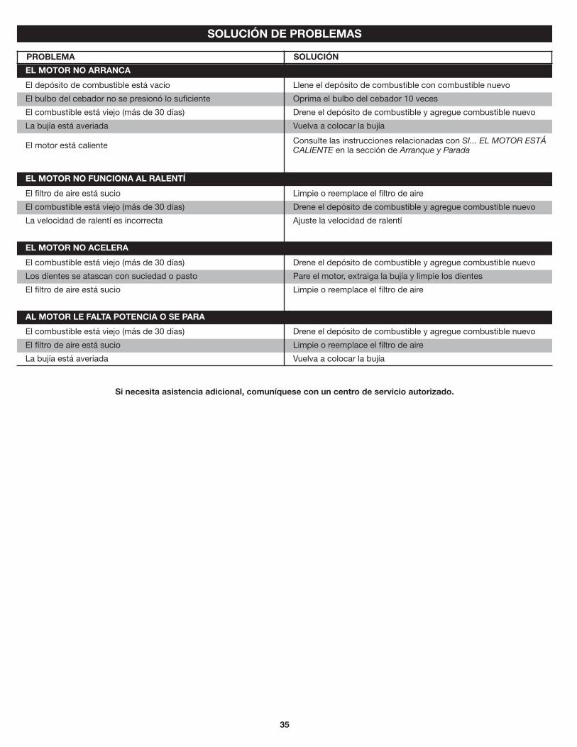
35
SOLUCIÓN DE PROBLEMAS
Si necesita asistencia adicional, comuníquese con un centro de servicio autorizado.
El depósito de combustible está vacío Llene el depósito de combustible con combustible nuevo
El bulbo del cebador no se presionó lo suficiente Oprima el bulbo del cebador 10 veces
El combustible está viejo (más de 30 días) Drene el depósito de combustible y agregue combustible nuevo
La bujía está averiada Vuelva a colocar la bujía
El motor está caliente Consulte las instrucciones relacionadas con SI... EL MOTOR ESTÁ CALIENTE en la sección de Arranque y Parada
El combustible está viejo (más de 30 días) Drene el depósito de combustible y agregue combustible nuevo
Los dientes se atascan con suciedad o pasto Pare el motor, extraiga la bujía y limpie los dientes
El filtro de aire está sucio Limpie o reemplace el filtro de aire
PROBLEMA SOLUCIÓN
El filtro de aire está sucio Limpie o reemplace el filtro de aire
El combustible está viejo (más de 30 días) Drene el depósito de combustible y agregue combustible nuevo
La velocidad de ralentí es incorrecta Ajuste la velocidad de ralentí
El combustible está viejo (más de 30 días) Drene el depósito de combustible y agregue combustible nuevo
El filtro de aire está sucio Limpie o reemplace el filtro de aire
La bujía está averiada Vuelva a colocar la bujía
EL MOTOR NO ARRANCA
EL MOTOR NO FUNCIONA AL RALENTÍ
EL MOTOR NO ACELERA
AL MOTOR LE FALTA POTENCIA O SE PARA

36
NOTAS

37
NOTAS

38
GARANTÍA
MTD LLC
GARANTÍA LIMITADA PARA EL PRODUCTO DE MANO DE MARCA CRAFTSMAN®
Garantía Limitada
La garantía limitada establecida en este documento es otorgada por MTD LLC al Comprador Inicial (como se define aquí) con respecto al nuevo producto manual de marca Craftsman ("Producto"). La presente garantía limitada no cubre los Sistemas de control de emisiones y no constituye una Declaración de garantía del control de las emisiones federal según lo definido por las leyes federales de los Estados Unidos. Consulte la Declaración de garantía de control de emisiones federal que se incluye en el manual del operador para conocer las garantías que cubren los Sistemas de control de emisiones.
Alcance de la Garantía Limitada
MTD LLC ofrece una garantía limitada al Comprador inicial para uso residencial o para uso no comercial del Producto: sujeto a las Exclusiones definidas aquí, durante el Período de Garantía (definido aquí). El "Comprador inicial" es la primera persona en comprar este Producto de un concesionario, distribuidor y/o vendedor minorista autorizado de productos de marca Crafstman (cada uno denominado "Vendedor minorista"). Excepto que se disponga lo contrario en el presente documento, el período de la garantía limitada para este nuevo Producto adquirido por el Comprador inicial es de dos (2) años a partir de la fecha de compra, como se indica en el comprobante de venta original correspondiente al Producto (“Período de la Garantía”).
Defectos de Mano de Obra o Materiales
Excepto por las Exclusiones, se garantiza que el Producto estará libre de defectos de fabricación en la mano de obra o los materiales durante el Período de la Garantía. Durante el Período de Garantía, MTD LLC tendrá la opción de reparar o reemplazar cualquier pieza original que esté cubierta por esta garantía limitada y que se determine que presenta un defecto de mano de obra o materiales.
Para Tener Derecho a esta Garantía Limitada, el Producto:
1. Debe haber sido comprado a un vendedor minorista autorizado de la marca Craftsman. 2. Debe haber sido adquirido por el Comprador Inicial dentro de los Estados Unidos. 3. Debe haberse usado únicamente para fines residenciales u otro tipo de uso no comercial. 4. Debe haber sido utilizado de una manera consistente con el uso normal y adecuado.
¿Quiénes Pueden Efectuar Reparaciones Bajo esta Garantía?
Para poder calificar para la garantía limitada aquí establecida, las reparaciones hechas bajo esta garantía deben ser realizadas por un proveedor de servicios de garantía autorizado.
Cómo Obtener Servicios Bajo esta Garantía Limitada
Para localizar un proveedor de servicio de garantía autorizado, póngase en contacto con su vendedor minorista autorizado o contáctese con www.craftsman.com/warranty, o llame gratis al 888-331-4569. PARA UN SERVICIO DE GARANTÍA NECESITARÁ PRESENTAR UNA COPIA DE SU FACTURA DE VENTA.

39
Lo que NO Cubre esta Garantía Limitada
Esta Garantía Limitada No Cubre lo Siguiente (las “Exclusiones”):
1. Los productos adquiridos fuera de los Estados Unidos. 2. Los daños producidos por la falta de mantenimiento y/o un mantenimiento inadecuado, según se describe en el manual del operador. 3. El desgaste normal resultante de usar el Producto. 4. El uso del Producto de manera no acorde al uso previsto para el mismo, como se describe en las instrucciones operativas, incluyendo,
sin limitación, abuso, uso indebido y/o descuidado del Producto o todo uso que no se compadezca y/o no cumpla con las instrucciones que figuran en el manual del operador.
5. Cualquier artículo fungible, consumible o de mantenimiento rutinario que requiera reemplazo o servicio como parte del mantenimiento normal, a menos que dichos artículos tengan defectos que causen fallas o desgaste prematuro dentro de los primeros treinta (30) días. Donde corresponda, los artículos de uso normal incluyen, entre otros, perillas, carretes externos, línea de corte, carretes interiores, poleas de arranque, cuerdas de arranque, correas de transmisión, cadenas de sierra, barras de guía, púas de cultivo, filtros, bujías, estuches de transporte, fundas o cuchillas.
6. Todo Producto que haya sido alterado o modificado de alguna manera que no se compadezca con el diseño original del producto o de alguna manera no aprobada.
7. Las reparaciones en concepto de pintura o los reemplazos por defectos en la pintura (que incluyen los materiales y la aplicación) están cubiertos por un período de tres (3) meses.
Esta Garantía No Cubre, y MTD LLC No Asume Ninguna Responsabilidad por lo Siguiente:
1. Pérdida de tiempo o pérdida de uso del Producto. 2. Gastos de transporte y otros gastos incurridos en relación con el transporte del Producto hacia y desde el proveedor de servicios autorizado. 3. Cualquier pérdida o daño a otros equipos o elementos personales. 4. Daño resultante de la instalación o el uso de cualquier accesorio o pieza que no sea del OEM (fabricante de equipo original) para utilizar
con el Producto.
Limitaciones:
1. NO HAY NINGUNA GARANTÍA, INCLUYENDO, SIN LIMITACIÓN, NINGUNA GARANTÍA TÁCITA DE COMERCIABILIDAD O APTITUD PARA UN DETERMINADO USO. PASADO EL PERÍODO DE GARANTÍA NO SE APLICARÁ NINGUNA GARANTÍA SEGÚN LO ESTABLECIDO PRECEDENTEMENTE RESPECTO DE LAS PIEZAS YA IDENTIFICADAS. NINGUNA OTRA GARANTÍA EXPRESA, SEA ESCRITA O VERBAL, A EXCEPCIÓN DE LA ARRIBA INDICADA, OTORGADA POR UNA PERSONA FÍSICA O JURÍDICA, INCLUYENDO UN CONCESIONARIO O COMERCIANTES, CON RESPECTO ALGÚN PRODUCTO SERÁ VINCULANTE PARA MTD LLC. DURANTE EL PERÍODO DE GARANTÍA, EL RECURSO EXCLUSIVO ES LA REPARACIÓN O LA SUSTITUCIÓN DE LA PIEZA DEFECTUOSA, SEGÚN LO ESTABLECIDO ANTERIORMENTE. (ALGUNOS ESTADOS NO PERMITEN LIMITACIONES SOBRE EL TIEMPO DE DURACIÓN DE UNA GARANTÍA TÁCITA, POR LO QUE LA LIMITACIÓN ANTERIOR PODRÍA NO APLICARLE A USTED.)
2. LAS DISPOSICIONES ESTABLECIDAS EN EL PRESENTE DOCUMENTO PREVÉN EL ÚNICO Y EXCLUSIVO RECURSO QUE SURGE DE LA VENTA. MTD LLC NO SERÁ RESPONSABLE POR DAÑOS O PÉRDIDAS INCIDENTALES O INDIRECTAS INCLUYENDO, SIN LIMITACIÓN, POR GASTOS DE TRANSPORTE O GASTOS SIMILARES O POR GASTOS DE ALQUILER PARA REEMPLAZAR PROVISORIAMENTE UN PRODUCTO GARANTIZADO. (ALGUNOS ESTADOS NO PERMITEN LA EXCLUSIÓN O LA LIMITACIÓN DE DAÑOS INCIDENTALES O CONSECUENTES, POR LO QUE QUE ES POSIBLE QUE LA EXCLUSIÓN O LIMITACIÓN ANTERIOR NO SE APLIQUE EN SU CASO).
3. En ningún caso el reembolso será superior al precio de compra del Producto vendido. La alteración de los elementos de seguridad del Producto anulará esta garantía limitada. Usted asume el riesgo y la responsabilidad por pérdidas, daños o lesiones personales y materiales tanto suyas como de terceros como consecuencia del uso o uso indebido o imposibilidad de usar este Producto.
Leyes Estatales y esta Garantía.
Esta garantía limitada le concede derechos legales específicos, y también es posible que tenga otros derechos, que varían de un estado a otro.

TO ORDER REPLACEMENT PARTS
OR SCHEDULE REPAIR SERVICE
PARA ORDENAR PIEZAS
O PEDIR SERVICIO DE REPARACIÓN
1-888-331-4569
PRODUCT MANUFACTURED BY: / PRODUCTO FABRICADO POR:
MTD LLC P.O. Box 361131
Cleveland, OH 44136-0019
CRAFTSMAN® IS A REGISTERED TRADEMARK OF STANLEY BLACK & DECKER, INC., USED UNDER LICENSE.
ES UNA MARCA REGISTRADA DE STANLEY BLACK & DECKER, INC., UTILIZADA BAJO LICENCIA.
© 2019 CRAFTSMAN
U.S. & CANADA ONLY • SÓLO EN EE.UU. Y CANADÁ