4 operations on data - 國立中興大學
TRANSCRIPT

4.1
4 Operations On Data
Foundations of Computer Science Cengage Learning

4.2
List the three categories of operations performed on data.
Perform unary and binary logic operations on bit patterns.
Distinguish between logic shift operations and arithmetic shift operations.
Perform addition and subtraction on integers when they are stored in two’s complement format.
❑ Perform addition and subtraction on integers when stored in sign-and-magnitude format.
❑ Perform addition and subtraction operations on reals stored in floating-point format.
Objectives After studying this chapter, the student should be able to:

4.3
4-1 LOGIC OPERATIONS
Logic operations refer to those operations that apply the same basic operation on individual bits of a pattern, or on two corresponding bits in two patterns. This means that we can define logic operations at the bit level and at the pattern level (more bits).

4.4
Logic operations at bit level A bit can take one of the two values: 0 or 1. We interpret 0 as the value false and 1 as the value true. Boolean algebra, named in honor of George Boole, belongs to a special field of mathematics called logic. In this section, we show briefly four bit-level operations that are used to manipulate bits: NOT, AND, OR, and XOR.
Boolean algebra and logic circuits are discussed in Appendix E.
i

4.5 Figure 4.1 Logic operations at the bit level

4.6
NOT The NOT operator is a unary operator: it takes only one input. The output bit is the complement of the input.
The AND operator is a binary operator: it takes two inputs. The output bit is 1 if both inputs are 1s and the output is 0 in the other three cases.
AND
For x = 0 or 1 x AND 0 → 0 0 AND x → 0 i

4.7
OR The OR operator is a binary operator: it takes two inputs. The output bit is 0 if both inputs are 0s and the output is 1 in other three cases.
The XOR operator is a binary operator like the OR operator, with only one difference: the output is 0 if both inputs are 1s.
XOR
For x = 0 or 1 x OR 1 → 1 1 OR x → 1 i
For x = 0 or 1 1 XOR x → NOT x x XOR 1 → NOT x
i

4.8
Example 4.1
In English we use the conjunction “or” sometimes to mean an inclusive-or, and sometimes to means an exclusive-or.
a. The sentence “I would like to have a car or a house” uses “or” in the inclusive sense—I would like to have a car, a house or both.
b. The sentence “Today is either Monday or Tuesday” uses “or” in the exclusive sense—today is either Monday or Tuesday, but it cannot be both.

4.9
Example 4.2
The XOR operator is not actually a new operator. We can always simulate it using the other three operators. The following two expressions are equivalent
x XOR y ↔ [x AND (NOT y)] OR [(NOT x) AND y]
The equivalence can be proved if we make the truth table for both.

4.10
Logic operations at pattern level The same four operators (NOT, AND, OR, and XOR) can be applied to an n-bit pattern. Figure 4.2 shows these four operators with input and output patterns.
Figure 4.2 Logic operators applied to bit patterns

4.11
Example 4.3
Use the NOT operator on the bit pattern 10011000.
Solution The solution is shown below. Note that the NOT operator changes every 0 to 1 and every 1 to 0.

4.12
Example 4.4 Use the AND operator on the bit patterns 10011000 and 00101010.
Solution The solution is shown below. Note that only one bit in the output is 1, where both corresponding inputs are 1s.

4.13
Example 4.5
Use the OR operator on the bit patterns 10011001 and 00101110.
Solution The solution is shown below. Note that only one bit in the output is 0, where both corresponding inputs are 0s.
4.14
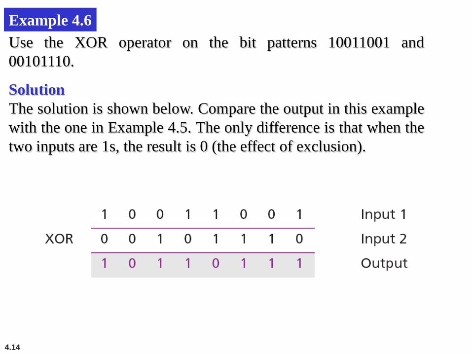
Example 4.6 Use the XOR operator on the bit patterns 10011001 and 00101110.
Solution The solution is shown below. Compare the output in this example with the one in Example 4.5. The only difference is that when the two inputs are 1s, the result is 0 (the effect of exclusion).

4.15
Applications
The four logic operations can be used to modify a bit pattern.
Complementing (NOT)
Unsetting (AND)
Setting (OR)
Flipping (XOR)

4.16
Example 4.7 Use a mask to unset (clear) the five leftmost bits of a pattern. Test the mask with the pattern 10100110.
Solution The mask is 00000111. The result of applying the mask is:

4.17
Example 4.8 Use a mask to set the five leftmost bits of a pattern. Test the mask with the pattern 10100110.
Solution The mask is 11111000. The result of applying the mask is:

4.18
Example 4.9 Use a mask to flip the five leftmost bits of a pattern. Test the mask with the pattern 10100110.
Solution The mask is 11111000. The result of applying the mask is:

4.19
4-2 SHIFT OPERATIONS
Shift operations move the bits in a pattern, changing the positions of the bits. They can move bits to the left or to the right. We can divide shift operations into two categories: logical shift operations and arithmetic shift operations.

4.20
Logical shift operations A logical shift operation is applied to a pattern that does not represent a signed number. The reason is that these shift operations may change the sign of the number that is defined by the leftmost bit in the pattern. We distinguish two types of logical shift operations, as described below:
Logical shift
Logical circular shift (Rotate)

4.21
Figure 4.3 Logical shift operations

4.22
Example 4.10
Use a logical left shift operation on the bit pattern 10011000.
Solution The solution is shown below. The leftmost bit is lost and a 0 is inserted as the rightmost bit.
Discarded
Added
4.23
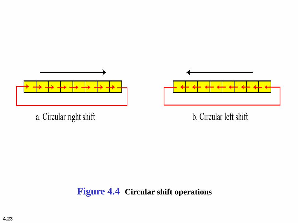
Figure 4.4 Circular shift operations

4.24
Example 4.11
Use a circular left shift operation on the bit pattern 10011000.
Solution The solution is shown below. The leftmost bit is circulated and becomes the rightmost bit.

4.25
Arithmetic shift operations Arithmetic shift operations assume that the bit pattern is a signed integer in two’s complement format. Arithmetic right shift is used to divide an integer by two, while arithmetic left shift is used to multiply an integer by two.
Figure 4.5 Arithmetic shift operations

4.26
Example 4.12
Use an arithmetic right shift operation on the bit pattern 10011001. The pattern is an integer in two’s complement format.
Solution The solution is shown below. The leftmost bit is retained and also copied to its right neighbor bit.
The original number was −103 and the new number is −52, which is the result of dividing −103 by 2 truncated to the smaller integer.
4.27
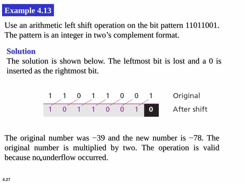
Example 4.13
Use an arithmetic left shift operation on the bit pattern 11011001. The pattern is an integer in two’s complement format.
Solution The solution is shown below. The leftmost bit is lost and a 0 is inserted as the rightmost bit.
The original number was −39 and the new number is −78. The original number is multiplied by two. The operation is valid because no underflow occurred.

4.28
Example 4.14
Use an arithmetic left shift operation on the bit pattern 01111111. The pattern is an integer in two’s complement format.
Solution The solution is shown below. The leftmost bit is lost and a 0 is inserted as the rightmost bit.
The original number was 127 and the new number is −2. Here the result is not valid because an overflow has occurred. The expected answer 127 × 2 = 254 cannot be represented by an 8-bit pattern.

4.29
Example 4.15
Assume that we have a pattern and we need to use the third bit (from the right) of this pattern in a decision-making process. We want to know if this particular bit is 0 or 1. The following shows how we can find out.
We can then test the result: if it is an unsigned integer 1, the target bit was 1, whereas if the result is an unsigned integer 0, the target bit was 0.

4.30
4-3 ARITHMETIC OPERATIONS
Arithmetic operations involve: 1. adding 2. subtracting 3. multiplying 4. dividing
We can apply these operations to integers and floating-point numbers.

4.31
Arithmetic operations on integers
There are more efficient procedures for multiplication and division, such as Booth procedures, but these are beyond the scope of this book. For this reason, we only discuss addition and subtraction of integers here.

4.32
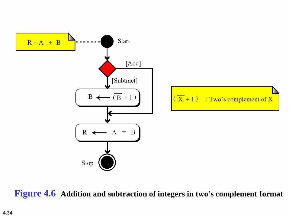
Two’s complement integers When the subtraction operation is encountered, the computer simply changes it to an addition operation, but makes two’s complement of the second number. In other words:
A − B ↔ A + (B + 1)
Where B is the one’s complement of B and (B + 1) means the two’s complement of B
4.33
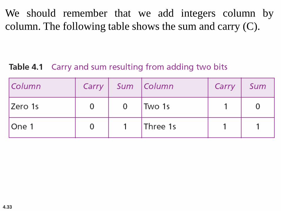
We should remember that we add integers column by column. The following table shows the sum and carry (C).
4.34
Figure 4.6 Addition and subtraction of integers in two’s complement format
4.35
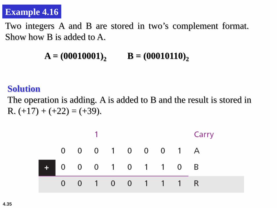
Example 4.16 Two integers A and B are stored in two’s complement format. Show how B is added to A.
Solution The operation is adding. A is added to B and the result is stored in R. (+17) + (+22) = (+39).
A = (00010001)2 B = (00010110)2

4.36
Example 4.17 Two integers A and B are stored in two’s complement format. Show how B is added to A.
Solution The operation is adding. A is added to B and the result is stored in R. (+24) + (−17) = (+7).
A = (00011000)2 B = (11101111)2

4.37
Example 4.18 Two integers A and B are stored in two’s complement format. Show how B is subtracted from A.
Solution The operation is subtracting. A is added to (B + 1) and the result is stored in R. (+24) − (−17) = (+41).
A = (00011000)2 B = (11101111)2

4.38
Example 4.19 Two integers A and B are stored in two’s complement format. Show how B is subtracted from A.
Solution The operation is subtracting. A is added to (B + 1) and the result is stored in R. (−35) − (+20) = (−55).
A = (11011101)2 B = (00010100)2

4.39
Example 4.20 Two integers A and B are stored in two’s complement format. Show how B is added to A.
Solution The operation is adding. A is added to B and the result is stored in R.
A = (01111111)2 B = (00000011)2
We expect the result to be 127 + 3 = 130, but the answer is −126. The error is due to overflow, because the expected answer (+130) is not in the range −128 to +127.

4.40
When we do arithmetic operations on numbers in a computer, we should remember that each number and the result should be in the range defined by
the bit allocation.
i
4.41
sign-and-magnitude integers Addition and subtraction for integers in sign-and-magnitude representation looks very complex. We have four different combination of signs (two signs, each of two values) for addition and four different conditions for subtraction. This means that we need to consider eight different situations. However, if we first check the signs, we can reduce these cases, as shown in Figure 4.7.

4.42
Figure 4.7 Addition and subtraction of integers in sign-and-magnitude format

4.43
Example 4.22 Two integers A and B are stored in sign-and-magnitude format. Show how B is added to A.
Solution The operation is adding: the sign of B is not changed. S = AS XOR BS = 1; RM = AM + (BM +1). Since there is no overflow, we need to take the two’s complement of RM. The sign of R is the sign of B. (+17) + ( −22) = (−5).
A = (0 0010001)2 B = (1 0010110)2

4.44
Example 4.23 Two integers A and B are stored in sign-and-magnitude format. Show how B is subtracted from A.
Solution The operation is subtracting: SB = SB. S = AS XOR BS = 1, RM = AM + (BM +1). Since there is an overflow, the value of RM is final. The sign of R is the sign of A. (−81) − (−22) = (−59).
A = (1 1010001)2 B = (1 0010110)2

4.46
Addition and subtraction of reals
Addition and subtraction of real numbers stored in floating-point numbers is reduced to addition and subtraction of two integers stored in sign-and-magnitude (combination of sign and mantissa) after the alignment of decimal points. Figure 4.8 shows a simplified version of the procedure (there are some special cases that we have ignored).

4.47
Figure 4.8 Addition and subtraction of reals in floating-point format

4.48
Example 4.24 Show how the computer finds the result of (+5.75) + (+161.875) = (+167.625).
Solution As we saw in Chapter 3, these two numbers are stored in floating-point format, as shown below, but we need to remember that each number has a hidden 1 (which is not stored, but assumed).
4.49
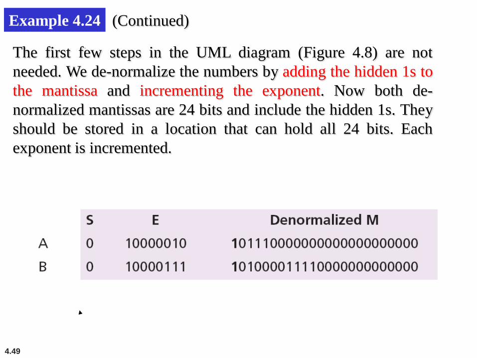
Example 4.24 (Continued)
The first few steps in the UML diagram (Figure 4.8) are not needed. We de-normalize the numbers by adding the hidden 1s to the mantissa and incrementing the exponent. Now both de-normalized mantissas are 24 bits and include the hidden 1s. They should be stored in a location that can hold all 24 bits. Each exponent is incremented.
4.50
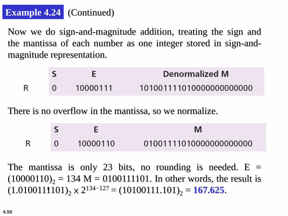
Example 4.24 (Continued)
Now we do sign-and-magnitude addition, treating the sign and the mantissa of each number as one integer stored in sign-and-magnitude representation.
There is no overflow in the mantissa, so we normalize.
The mantissa is only 23 bits, no rounding is needed. E = (10000110)2 = 134 M = 0100111101. In other words, the result is (1.0100111101)2 × 2134−127 = (10100111.101)2 = 167.625.

4.51
Example 4.25 Show how the computer finds the result of (+5.75) + (−7.0234375) = − 1.2734375.
Solution These two numbers can be stored in floating-point format, as shown below:
De-normalization results in:

4.52
Example 4.25 (Continued)
Alignment is not needed (both exponents are the same), so we apply addition operation on the combinations of sign and mantissa. The result is shown below, in which the sign of the result is negative:
Now we need to normalize. We decrement the exponent three times and shift the de-normalized mantissa to the left three positions:
4.53
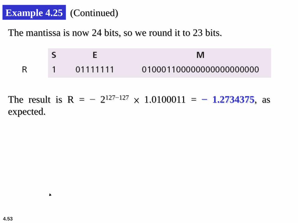
Example 4.25 (Continued)
The mantissa is now 24 bits, so we round it to 23 bits.
The result is R = − 2127−127 × 1.0100011 = − 1.2734375, as expected.