5 gallon duo paint sprayer 306713n - graco inc.€¦ · 5 gallon duo paint sprayer a portable one...
TRANSCRIPT

5 Gallon Duo Paint SprayerA portable one or two gun circulating supply package.
360 psi (25 bar) Maximum Working Pressure180 psi (12 bar) Maximum Air Inlet Pressure
Part No. 205585, Series DWith Agitator
Part No. 205584, Series AWithout Agitator
Part No. 205595, Series EBare Pump Assembly
Instructions – Parts List
306713N
Important Safety Instructions.Read all warnings and instructions inthis manual. Save these instructions. See page 2 for Table of Contents
Model 205585 Shown
0359
II 1/2 G T6
II 1/2 G T6
II 1/2 G T6ITS03ATEX11227
ITS03ATEX11251
ITS03ATEX11251
02121B

2 306713
Table of ContentsWarnings 2. . . . . . . . . . . . . . . . . . . . . . . . . . . . . . . . . . . . . . Setup 4. . . . . . . . . . . . . . . . . . . . . . . . . . . . . . . . . . . . . . . . . Operation 8. . . . . . . . . . . . . . . . . . . . . . . . . . . . . . . . . . . . . Troubleshooting 14. . . . . . . . . . . . . . . . . . . . . . . . . . . . . . . Service 14. . . . . . . . . . . . . . . . . . . . . . . . . . . . . . . . . . . . . . Parts 18. . . . . . . . . . . . . . . . . . . . . . . . . . . . . . . . . . . . . . . . Technical Data 22. . . . . . . . . . . . . . . . . . . . . . . . . . . . . . . . Dimensions 23. . . . . . . . . . . . . . . . . . . . . . . . . . . . . . . . . . . Graco Warranty 24. . . . . . . . . . . . . . . . . . . . . . . . . . . . . . . Graco Information 24. . . . . . . . . . . . . . . . . . . . . . . . . . . . .
SymbolsWarning Symbol
WARNINGThis symbol alerts you to the possibility of seriousinjury or death if you do not follow the instructions.
Caution Symbol
CAUTIONThis symbol alerts you to the possibility of damage toor destruction of equipment if you do not follow theinstructions.
WARNING
INSTRUCTIONS
EQUIPMENT MISUSE HAZARD
Equipment misuse can cause the equipment to rupture or malfunction and result in serious injury.
� This equipment is for professional use only.
� Read all instruction manuals, tags, and labels before operating the equipment.
� Use the equipment only for its intended purpose. If you are not sure, call your Graco distributor.
� Do not alter or modify this equipment.
� Check equipment daily. Repair or replace worn or damaged parts immediately.
� Do not exceed the maximum working pressure of the lowest rated system component. Refer to theTechnical Data on page 22 for the maximum working pressure of this equipment.
� Use fluids and solvents which are compatible with the equipment wetted parts. Refer to the Tech-nical Data section of all equipment manuals. Read the fluid and solvent manufacturer’s warnings.
� Do not use 1,1,1–trichloroethane, methylene chloride, other halogenated hydrocarbon solvents orfluids containing such solvents in aluminum equipment. Such use could result in a serious chemicalreaction, with the possibility of explosion.
� Do not use hoses to pull equipment.
� Route hoses away from traffic areas, sharp edges, moving parts, and hot surfaces. Do not exposeGraco hoses to temperatures above 82�C (180�F) or below –40�C (–40�F).
� Wear hearing protection when operating this equipment.
� Do not lift pressurized equipment.
� Comply with all applicable local, state, and national fire, electrical, and safety regulations.

306713 3
WARNINGFIRE AND EXPLOSION HAZARD
Improper grounding, poor ventilation, open flames or sparks can cause a hazardous condition andresult in a fire or explosion and serious injury.
� Ground the equipment and the object being sprayed. Refer to Grounding on page 4.
� If there is any static sparking or you feel an electric shock while using this equipment, stop spray-ing immediately. Do not use the equipment until you identify and correct the problem.
� Provide fresh air ventilation to avoid the buildup of flammable fumes from solvents or the fluidbeing sprayed.
� Keep the spray area free of debris, including solvent, rags, and gasoline.
� Electrically disconnect all equipment in the spray area.
� Extinguish all open flames or pilot lights in the spray area.
� Do not smoke in the spray area.
� Do not turn on or off any light switch in the spray area while operating or if fumes are present.
� Do not operate a gasoline engine in the spray area.
TOXIC FLUID HAZARD
Hazardous fluid or toxic fumes can cause serious injury or death if splashed in the eyes or on the skin,inhaled, or swallowed.
� Know the specific hazards of the fluid you are using.
� Store hazardous fluid in an approved container. Dispose of hazardous fluid according to all local,state and national guidelines.
� Always wear protective eyewear, gloves, clothing and respirator as recommended by the fluid andsolvent manufacturer.
MOVING PARTS HAZARD
Moving parts, such as the air motor piston, can pinch or amputate your fingers.
� Keep clear of all moving parts when starting or operating the pump.
� Before servicing the equipment, follow the Pressure Relief Procedure on page 8 to prevent theequipment from starting unexpectedly.

4 306713
SetupNOTE: Reference numbers and letters in parenthesesin the text refer to the callouts in the figures and theparts drawing.
Prepare the Operator
All persons who operate the equipment must betrained in the safe, efficient operation of all systemcomponents as well as the proper handling of all fluids.All operators must thoroughly read all instructionmanuals, tags, and labels before operating the equip-ment.
Prepare the Site
The pump requires 3.75 scfm (0.105 m�/min) of com-pressed air while operating at 100 psi (7 bar) air pres-sure and 60 cycles per minute. Ensure that you havean adequate compressed air supply.
Refer to Fig. 2. Bring a compressed air supply line (D)from the air compressor to the pump location. Be sureall air hoses (F) are properly sized and pressure-ratedfor your system. Use only electrically conductivehoses.
Keep the site clear of any obstacles or debris thatcould interfere with the operator’s movement.
Have a grounded, metal pail available for use whenflushing the system or draining the fluid filter.
Grounding
WARNINGFIRE AND EXPLOSION HAZARDBefore operating the pump, ground thesystem as explained below. Also readthe section FIRE AND EXPLOSIONHAZARD on page 3.
1. Pump: use a ground wire and clamp. See Fig. 1.Loosen the grounding lug locknut (W) and washer(X). Insert one end of the ground wire (Y) into theslot in lug (Z) and tighten the locknut securely.Connect the other end of the wire to a true earthground. Order Part No. 237569 Ground Wire andClamp (supplied with Model 205585).
Fig. 1
W
XY
Z
0864
2. Air and fluid hoses: use only electrically conductivehoses.
3. Air compressor: follow manufacturer’s recommen-dations.
4. Spray gun: ground through connection to properlygrounded hoses and pump.
5. Fluid supply container: follow your local code.
6. Object being sprayed: follow your local code.
7. Solvent pails used when flushing: follow your localcode. Use only metal pails, which are conductive,placed on a grounded surface. Do not place thepail on a nonconductive surface, such as paper orcardboard, which interrupts the grounding continu-ity.
8. To maintain grounding continuity when flushing orrelieving pressure, hold a metal part of the spraygun firmly to the side of a grounded metal pail,then trigger the gun.
306713 5
SetupAvailable Accessories (must bepurchased separately)
NOTE: Always use Genuine Graco Parts and Acces-sories, available from your Graco distributor. If yousupply your own accessories, be sure they are ade-quately sized and pressure rated for your system.
Fig. 2 is only a guide for selecting and installing sys-tem components and accessories. Contact your Gracodistributor for assistance in designing a system to suityour particular needs.
Air Line Accessories
WARNINGA red-handled bleed-type master air valve (E) isrequired in your system to help reduce the risk ofserious injury, including splashing of fluid in theeyes or on the skin, and injury from moving parts ifyou are adjusting or repairing the pump.
The bleed-type master air valve relieves air trappedbetween this valve and the pump after the air isshut off. Trapped air can cause the pump to cycleunexpectedly. Locate the valve close to the pump.
� The red-handled bleed-type master air valve (E)is required in your system to relieve air trappedbetween it and the air motor when the valve isclosed (see the WARNING above). Be sure thebleed valve is easily accessible from the pump, andis located downstream from the air filter/regulator(G). Order Part No. 113329 Bleed Valve (suppliedwith Model 205585).
� The air filter/regulator (G) controls pump speedand outlet pressure by adjusting the air pressure tothe pump and the air spray gun. It also removesharmful dirt and moisture from the compressed airsupply. Locate the pump air filter/regulator up-stream from the bleed-type master air valve (E).Also, supply an air filter/regulator at each spraybooth.
� An air line lubricator (J) provides automatic airmotor lubrication. Install downstream from thepump air filter/regulator (G).
� Install additional air bleed valves (M) at each airline drop, to isolate accessories for servicing.
Fluid Line Accessories
WARNINGA fluid drain valve (K) is required in your system tohelp reduce the risk of serious injury, includingsplashing of fluid in the eyes or on the skin.
The fluid drain valve assists in relieving fluid pres-sure in the displacement pump, hose, and gun.Triggering the gun to relieve pressure may not besufficient.
� The fluid drain valve (K) is required in your sys-tem to relieve fluid pressure in the hose and gun(see the WARNING above).
� Install a fluid filter (H) to remove impurities fromthe fluid before it reaches the spray gun (L).
� Install a fluid pressure regulator (A) to provideprecise fluid pressure control at each spray booth.
Supplied Components
Refer to Fig. 3.
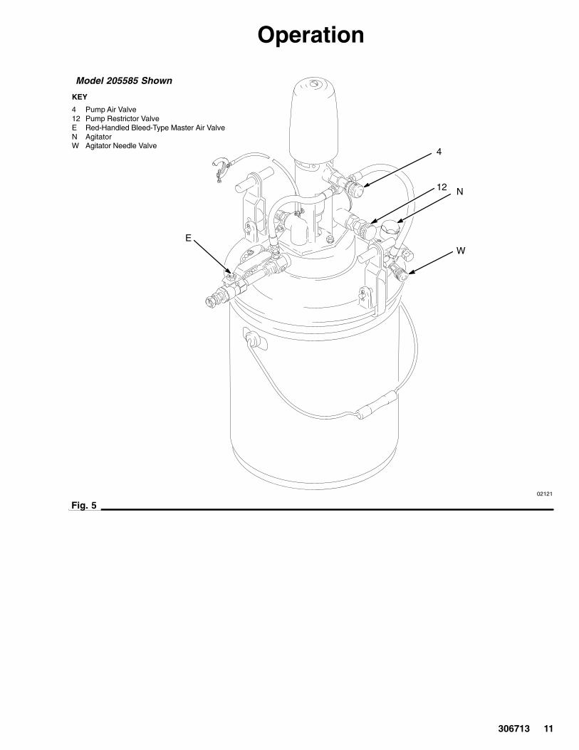
� The pump air valve (4) controls the pump speedby adjusting the supply of air to the pump.
� The pump restrictor valve (12) adjusts the fluidpressure by restricting the fluid flow.
� The agitator (N) is supplied on Model 205585only. To prevent fluid from settling out, operate theagitator as explained in its separate manual306565.
02126
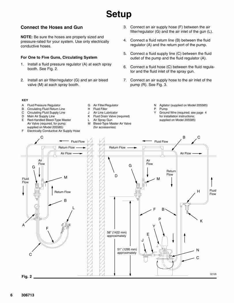
KEY
A Fluid Pressure RegulatorB Circulating Fluid Return LineC Circulating Fluid Supply LineD Main Air Supply LineE Red-Handled Bleed-Type Master
Air Valve (required, for pump;supplied on Model 205585)
F Electrically Conductive Air Supply Hose
G Air Filter/RegulatorH Fluid FilterJ Air Line LubricatorK Fluid Drain Valve (required)L Air Spray GunM Bleed-Type Master Air Valve
(for accessories)
N Agitator (supplied on Model 205585)P PumpY Ground Wire (required; see page 4
for installation instructions;supplied on Model 205585)
Fig. 2
G
A
G
J
E
YK
H
B
C
C B
D
B
C
F56” (1422 mm)approximately
51” (1295 mm)approximately
F
C
L
M
N
P
M
Fluid Flow Fluid Flow
Air Flow
Return Flow Return Flow
Air Flow
Return Flow FluidFlow
ReturnFlow
FluidFlow
AirFlow
AirFlow
6 306713
SetupConnect the Hoses and Gun
NOTE: Be sure the hoses are properly sized andpressure-rated for your system. Use only electricallyconductive hoses.
For One to Five Guns, Circulating System
1. Install a fluid pressure regulator (A) at each spraybooth. See Fig. 2.
2. Install an air filter/regulator (G) and an air bleedvalve (M) at each spray booth.
3. Connect an air supply hose (F) between the airfilter/regulator (G) and the air inlet of the gun (L).
4. Connect a fluid return line (B) between the fluidregulator (A) and the return port of the pump.
5. Connect a fluid supply line (C) between the fluidoutlet of the pump and the fluid regulator (A).
6. Connect a fluid hose (C) between the fluid regula-tor and the fluid inlet of the spray gun.
7. Connect an air supply hose to the air inlet of thepump (R). See Fig. 3.
306713 7
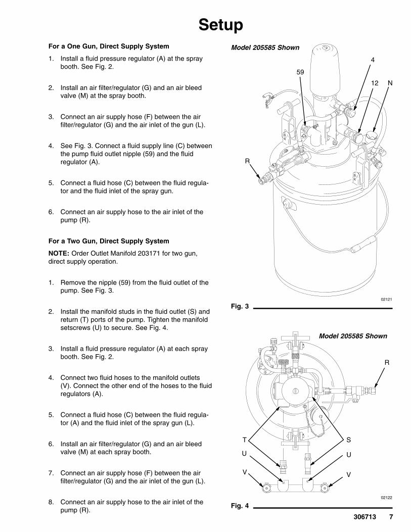
SetupFor a One Gun, Direct Supply System
1. Install a fluid pressure regulator (A) at the spraybooth. See Fig. 2.
2. Install an air filter/regulator (G) and an air bleedvalve (M) at the spray booth.
3. Connect an air supply hose (F) between the airfilter/regulator (G) and the air inlet of the gun (L).
4. See Fig. 3. Connect a fluid supply line (C) betweenthe pump fluid outlet nipple (59) and the fluidregulator (A).
5. Connect a fluid hose (C) between the fluid regula-tor and the fluid inlet of the spray gun.
6. Connect an air supply hose to the air inlet of thepump (R).
For a Two Gun, Direct Supply System
NOTE: Order Outlet Manifold 203171 for two gun,direct supply operation.
1. Remove the nipple (59) from the fluid outlet of thepump. See Fig. 3.
2. Install the manifold studs in the fluid outlet (S) andreturn (T) ports of the pump. Tighten the manifoldsetscrews (U) to secure. See Fig. 4.
3. Install a fluid pressure regulator (A) at each spraybooth. See Fig. 2.
4. Connect two fluid hoses to the manifold outlets(V). Connect the other end of the hoses to the fluidregulators (A).
5. Connect a fluid hose (C) between the fluid regula-tor (A) and the fluid inlet of the spray gun (L).
6. Install an air filter/regulator (G) and an air bleedvalve (M) at each spray booth.
7. Connect an air supply hose (F) between the airfilter/regulator (G) and the air inlet of the gun (L).
8. Connect an air supply hose to the air inlet of thepump (R).
02121
Fig. 3
59
R
Model 205585 Shown
4
12 N
02122
Fig. 4
ST
UU
VV
R
Model 205585 Shown

8 306713
OperationPressure Relief Procedure
WARNINGPRESSURIZED EQUIPMENT HAZARDThe system pressure must be manually relieved toprevent the system from starting or spraying acci-dentally. To reduce the risk of an injury from acci-dental spray from the gun, splashing fluid, ormoving parts, follow the Pressure Relief Proce-dure whenever you:
� are instructed to relieve the pressure,� stop spraying,� check or service any of the system equipment,� or install or clean the spray nozzle.
1. Close the red-handled bleed-type master air valve(E, required in your system). Leave the pump airvalve (4) open.
2. Close the pump restrictor valve (12).
3. Shut off the air to the agitator (if used).
4. Hold a metal part of the gun firmly to the side of agrounded metal pail, and trigger the gun to relievepressure.
5. Open the drain valve (required in your system),having a container ready to catch the drainage.
6. Leave the drain valve open until you are ready tospray again.
If you suspect that the spray nozzle or hose is com-pletely clogged, or that pressure has not been fullyrelieved after following the steps above, very slowlyloosen the nozzle retaining ring or hose end couplingand relieve pressure gradually, then loosen completely.Now clear the nozzle or hose.
Packing Nut
WARNINGTo reduce the risk of serious injury whenever youare instructed to relieve pressure, always follow thePressure Relief Procedure at left.
Check the tightness of the packing nut (106) periodi-cally. The nut should be tight enough to prevent leak-age. Do not overtighten the packing nut. Relievepressure before adjusting the nut.
Flush the Pump Before First Use
The pump is tested with lightweight oil, which is left into protect the pump parts. If the fluid you are usingmay be contaminated by the oil, flush it out with acompatible solvent. See Flushing on page 12.
Lubrication
If you are not using an accessory air line lubricator,manually lubricate the motor daily. Disconnect the airline at the pump air inlet, place about 15 drops of lightmachine oil in the pump air inlet, reconnect the air lineand turn on the air supply to blow air into the motor.
Using the Agitator
When starting the agitator, gradually increase thespeed of the agitator by turning its needle valve (W)until a vortex begins to form in the fluid. Reduce thespeed slightly. See Fig. 5.
For further agitator operating instructions, refer to theseparate agitator manual 306565.

306713 9
OperationPrime the Pump (Direct Supply Systems)
1. See Figs. 2 and 5. Remove the spray nozzle fromthe gun. See the gun instruction manual.
2. Close all bleed-type air valves (E, M).
3. Close the pump air filter/regulator (G).
4. Close the fluid drain valve (K).
5. Check that all fittings throughout the system aretightened securely.
6. Connect the air supply line to the pump air inlet.
7. Open the bleed-type air valves (E, M). Open theair filter/regulator (G).
8. Hold a metal part of the gun firmly to the side of agrounded metal pail and hold the trigger open.
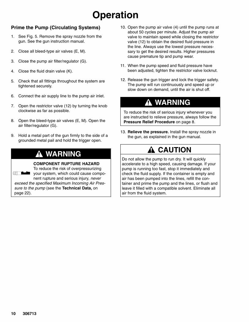
WARNINGCOMPONENT RUPTURE HAZARDTo reduce the risk of overpressurizingyour system, which could cause compo-nent rupture and serious injury, never
exceed the specified Maximum Incoming Air Pres-sure to the pump (see the Technical Data, onpage 22).
9. Slowly open the pump air valve (4) until the pumpstarts. Use the air valve to control pump speedand fluid pressure. Always use the lowest pressurenecessary to get the desired results. Higher pres-sures cause premature nozzle and pump wear.
10. Cycle the pump slowly until all air is pushed outand the pump and hoses are fully primed.
11. Release the gun trigger and lock the trigger safety.The pump should stall against pressure.
12. With the pump and lines primed, and with ade-quate air pressure and volume supplied, the pumpwill start and stop as you open and close the gun.
WARNINGTo reduce the risk of serious injury whenever youare instructed to relieve pressure, always follow thePressure Relief Procedure on page 8.
13. Relieve the pressure. Install the spray nozzle inthe gun, as explained in the gun manual.
CAUTIONDo not allow the pump to run dry. It will quicklyaccelerate to a high speed, causing damage. If yourpump is running too fast, stop it immediately andcheck the fluid supply. If the container is empty andair has been pumped into the lines, refill the con-tainer and prime the pump and the lines, or flush andleave it filled with a compatible solvent. Eliminate allair from the fluid system.
10 306713
OperationPrime the Pump (Circulating Systems)
1. See Fig. 5. Remove the spray nozzle from thegun. See the gun instruction manual.
2. Close all bleed-type air valves (E, M).
3. Close the pump air filter/regulator (G).
4. Close the fluid drain valve (K).
5. Check that all fittings throughout the system aretightened securely.
6. Connect the air supply line to the pump air inlet.
7. Open the restrictor valve (12) by turning the knobclockwise as far as possible.
8. Open the bleed-type air valves (E, M). Open theair filter/regulator (G).
9. Hold a metal part of the gun firmly to the side of agrounded metal pail and hold the trigger open.
WARNINGCOMPONENT RUPTURE HAZARDTo reduce the risk of overpressurizingyour system, which could cause compo-nent rupture and serious injury, never
exceed the specified Maximum Incoming Air Pres-sure to the pump (see the Technical Data, onpage 22).
10. Open the pump air valve (4) until the pump runs atabout 50 cycles per minute. Adjust the pump airvalve to maintain speed while closing the restrictorvalve (12) to obtain the desired fluid pressure inthe line. Always use the lowest pressure neces-sary to get the desired results. Higher pressurescause premature tip and pump wear.
11. When the pump speed and fluid pressure havebeen adjusted, tighten the restrictor valve locknut.
12. Release the gun trigger and lock the trigger safety.The pump will run continuously and speed up orslow down on demand, until the air is shut off.
WARNINGTo reduce the risk of serious injury whenever youare instructed to relieve pressure, always follow thePressure Relief Procedure on page 8.
13. Relieve the pressure. Install the spray nozzle inthe gun, as explained in the gun manual.
CAUTIONDo not allow the pump to run dry. It will quicklyaccelerate to a high speed, causing damage. If yourpump is running too fast, stop it immediately andcheck the fluid supply. If the container is empty andair has been pumped into the lines, refill the con-tainer and prime the pump and the lines, or flush andleave it filled with a compatible solvent. Eliminate allair from the fluid system.
306713 11
Operation
02121
KEY
4 Pump Air Valve12 Pump Restrictor ValveE Red-Handled Bleed-Type Master Air ValveN AgitatorW Agitator Needle Valve
Fig. 5
Model 205585 Shown
E
4
12 N
W

12 306713
OperationShutdown and Care of the Pump
WARNINGTo reduce the risk of serious injury whenever youare instructed to relieve pressure, always follow thePressure Relief Procedure on page 8.
For overnight shutdown, stop the pump at the bottomof its stroke to prevent fluid from drying on the ex-posed displacement rod and damaging the throatpackings. Relieve the pressure.
Always flush the pump before the fluid dries on thedisplacement rod. See Flushing below.
Flushing
WARNINGFIRE AND EXPLOSION HAZARDBefore flushing, read the section FIREAND EXPLOSION HAZARD on page3. Be sure the entire system and flush-ing pails are properly grounded. Refer toGrounding on page 4.
Flush the pump:
� Before the first use
� When changing colors or fluids
� Before fluid can dry or settle out in a dormant pump(check the pot life of catalyzed fluids)
� Before storing the pump.
Flush with a fluid that is compatible with the fluid youare pumping and with the wetted parts in your system.Check with your fluid manufacturer or supplier forrecommended flushing fluids and flushing frequency.
CAUTIONNever leave water or water-base fluid in the pumpovernight. If you are pumping water-base fluid, flushwith water first, then with a rust inhibitor such asmineral spirits. Relieve the pressure, but leave therust inhibitor in the pump to protect the parts fromcorrosion.
WARNINGTo reduce the risk of serious injury whenever youare instructed to relieve pressure, always follow thePressure Relief Procedure on page 8.
1. Relieve the pressure.
2. Remove the spray nozzle from the gun.
3. Hold a metal part of the gun firmly to the side of agrounded metal pail.
4. Start the pump. Always use the lowest possiblefluid pressure when flushing.
5. Trigger the gun.
6. Flush the system until clear solvent flows from thegun.
7. Relieve the pressure.
8. Clean the spray nozzle separately, then reinstall it.

306713 13
Notes

14 306713
TroubleshootingProblem Cause Solution
Low fluid output. Fluid line, air line, or spray gunclogged.
Check and clear.
Clogged fluid regulator or manifold. Check and clear.
Restricted main air supply. Check. Open bleed-type master airvalves.
Empty fluid supply container. Refill.
Wrong restrictor valve setting. Adjust; see page 10.
Dried fluid on the displacement rod. Clean the pump. Always stop thepump at the bottom of its stroke.
Worn pump valves or packings. Replace. See page 16.
Erratic agitator operation. Low air supply. Increase the air supply.
The agitator motor is rusted or dirty. See manual 306565 to service.
NOTE: Check all possible causes and solutions before disassembling the unit.
ServiceBefore You Start
1. Have all the necessary repair parts on hand.Recommended spare parts are indicated in theparts list with a check mark, for example (18�).
2. Repair Kit 207848 is available. Parts included inthe kit are marked with an asterisk, for example(102*). Use all the parts in the kit for the bestresults.
3. Use a compatible solvent to clean parts. Inspectparts for wear or damage and replace as needed.Scoring or irregular surfaces on the displacementrod (111) or polished inner wall of the cylinder (110)cause premature packing wear and leaking. Checkthese parts by holding the parts up to a light at aslight angle.
4. Flush the system, if possible. See page 12.
5. Disconnect the hoses from the pump and removeit from its mounting. Clamp the pump in a vise.

306713 15
Service
WARNINGTo reduce the risk of injury from trapped air pres-sure when servicing the air motor, always removeair cap (11) from air cylinder (47) before removingair cylinder from base (68).
Air Motor
1. Remove the shield capscrew (28) and the shield(56).
2. Unscrew the air cap (11) from the air cylinder (47).To remove the spring (35), gently pry under thecoils in the direction of the helix. Check the springand gasket (60) and replace as necessary.
3. Unscrew the air cylinder (47) from the base.
4. Hold the air exhaust plate (18) with a pliers (P) andthe flats of the air piston rod (10) with a wrench(N), and unscrew the piston and valve assembly(13). See Fig. 6. Remove the washer (37) andspring (36).
5. Disassemble and wash the parts thoroughly in acompatible, non-flammable solvent. Blow dry andinspect the parts for wear or damage.
6. If any valve plate spacers (15) are damaged,replace all three to maintain the correct clearancebetween the valve plates (17, 18) and the seats.See Fig. 7.
7. When reassembling, apply locking compound tothe threads of the screws and torque to 10–14 in-lb(1.1–1.6 N�m). With the washer (37) in place,apply thread sealant to the threads of the piston.Carefully screw the piston (11) onto the shaft (23)by hand so it is securely fastened. Do not use apliers on the air exhaust plate while tightening.When installed, there should be a 0.8 mm (0.032in.) minimum clearance between the washer (37)and the piston shaft shoulder. See Fig. 6.
Restrictor Valve
1. Remove the stem (12) and o-ring (34) from thebase. See Fig. 8.
2. Remove the seat (57) from the pump return portwith a screwdriver.
3. Clean and inspect all parts for wear or damageand replace if necessary.
02124Fig. 6
1
N
18P
Do not use a pliers on the air exhaust plate while tightening.
1
10
37
2Minimum 0.8 mm (0.032 in.) clearance between washer (37)and piston shaft shoulder.
2
13
02125
Fig. 7
1
2
1417
15
18
Apply locking compound to threads.
Torque to 10–14 in-lb (1.1–1.6 N�m).
1
1 2
02130
Fig. 857
34
12

16 306713
ServiceDisplacement Pump
Intake Valve1. Unscrew the intake valve (109*) from the cylinder
(110*) and disassemble. See Detail B of Fig. 9.
2. Clean and inspect all parts for wear or damage.
3. Reassemble the valve. To reseat the ball (102*),hold it against the seat with a brass rod and tapwith a hammer. Unless further service is needed,apply thread sealant to the threads of the intakevalve, screw it into the cylinder, and tighten se-curely.
Piston1. Unscrew the cylinder (110*) from the outlet hous-
ing (112) and pull the cylinder down to expose thepiston. Unscrew the piston stud (107) and removethe packings (103*), ball (101*), and washers (104,105). See Detail B of Fig. 9.
2. Clean and inspect all parts for wear or damageand replace them if necessary.
3. To reseat the ball (101*), hold it against the seatwith a brass rod and tap with a hammer. Reas-semble in the reverse order of disassembly. Screwthe stud (107) into the displacement rod (111) andtorque to 20–30 ft-lb (27–41 N�m).
Throat Packings1. To remove the displacement pump, remove the
lower locknut (39) from the return tube (64). Dis-connect the union (30) from the supply tube (62).Remove the cotter pin (27) to free the upper end ofthe connecting rod (63). Remove the cotter pinfrom the lower end of the connecting rod andunscrew the rod from the displacement rod (111).See Detail A of Fig. 9.
2. Unscrew the cylinder (110*) from the outlet hous-ing (112). If the displacement rod (111) is seized bydried fluid, soak in a compatible solvent beforedisassembling; do not try to break loose by twist-ing the rod.
3. Unscrew the packing nut (106) and remove thebearing (113*), packing (114*), and o-ring (115*).Clean and inspect all parts for wear or damageand replace if necessary.
4. Make sure that all parts are completely free ofpaint fillers and pigments. Fill the displacement rodcavity with heavy grease and reassemble in thereverse order of disassembly.
5. When reconnecting the displacement pump to theair motor, first tighten the union (30) onto thesupply tube (62), then screw the upper nut (39) onthe return tube down to the outlet housing (112)and lock in place with the lower lockwasher (25)and nut (39).

306713 17
Service
Fig. 9
1
3
4
2
05693
See Fig. 7.
See Detail A at left.
See Detail B at left.
1
2
3
Detail A: Pump Throat
Detail B: Intake Valve and piston Valve
28
56
55
35
47
12
Torque to 20–30 ft-lb (27–41 N�m).
4
11
*60
373638*31*
10
33*
61
12
64
63
62
*24
*27
30
112 39
25
39
111
110
109109
*102108
107
*101
110
111
105
103*
104
103*
105
39
25
39
115*
113*
54*
106
27*64
6362
30
*114
112
110
5 Lips face up.
6 Lips face down.
5
6
65
18 306713
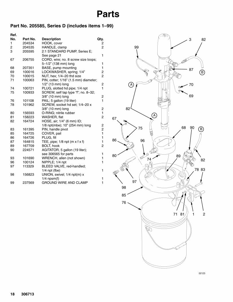
PartsPart No. 205585, Series D (includes items 1–99)
Ref.No. Part No. Description Qty.1 204534 HOOK, cover 22 204535 HANDLE, clamp 23 205595 2:1 STANDARD PUMP, Series E;
See page 21 167 206755 CORD, wire; no. 8 screw size loops;
5–1/2” (138 mm) long 168 207351 BASE, pump mounting 169 100016 LOCKWASHER, spring; 1/4” 270 100015 NUT, hex; 1/4–20 thd size 271 100063 PIN, cotter; 1/16” (1.5 mm) diameter;
1/2” (13 mm) long 274 100721 PLUG, slotted hd pipe; 1/4 npt 175 100933 SCREW, self tap type “f”; no. 8–32;
3/8” (10 mm) long 276 101108 PAIL; 5 gallon (19 liter) 178 101962 SCREW, socket hd set; 1/4–20 x
3/8” (10 mm) long 280 156593 O-RING; nitrile rubber 181 158223 WASHER, flat 282 164724 HOSE, air; 1/4” (6 mm) ID;
1/8 npt(mbe); 10” (254 mm) long 283 161395 PIN, handle pivot 285 164725 COVER, pail 186 164726 PLUG, fill 187 164815 TEE, pipe; 1/8 npt (m x f x f) 189 167709 BOLT, hook 290 224571 AGITATOR, 5 gallon (19 liter);
see 306565 for parts 193 101690 WRENCH, allen (not shown) 196 100124 NIPPLE; 1/4 npt 197 113329 BLEED VALVE, red-handled;
1/4 npt (fbe) 198 156823 UNION, swivel; 1/4 npt(m) x
1/4 npsm(f) 199 237569 GROUND WIRE AND CLAMP 1
02123
A
A
B
B
1 2
3
67
68
71
74
76
81
82
82
82
83
85
86
87
90
99
96
97
98
80 89
69
70
78
75

306713 19
PartsPart No. 205584, Series A (includes items 1–89)
Ref.No. Part No. Description Qty.1 204534 HOOK, cover 22 204535 HANDLE, clamp 23 205595 2:1 STANDARD PUMP, Series E;
See page 21 167 206755 CORD, wire; no. 8 screw size loops;
5–1/2” (138 mm) long 168 207351 BASE, pump mounting 169 100016 LOCKWASHER, spring; 1/4” 270 100015 NUT, hex; 1/4–20 thd size 271 100063 PIN, cotter; 1/16” (1.5 mm) diameter;
1/2” (13 mm) long 272 100403 PLUG, pipe 174 100721 PLUG, slotted hd pipe; 1/4 npt 175 100933 SCREW, self tap type “f”; no. 8–32;
3/8” (10 mm) long 276 101108 PAIL; 5 gallon (19 liter) 177 101342 PLUG, button 178 101962 SCREW, socket hd set; 1/4–20 x
3/8” (10 mm) long 280 156593 O-RING; nitrile rubber 181 158223 WASHER, flat 282 164724 HOSE, air; 1/4” (6 mm) ID;
1/8 npt(mbe); 10” (254 mm) long 283 161395 PIN, handle pivot 284 162453 NIPPLE, pipe; 1/4 npt x 1/4 npsm 185 164725 COVER, pail 186 164726 PLUG, fill 187 164815 TEE, pipe; 1/8 npt (m x f x f) 189 167709 BOLT, hook 2
05979
A
A
1 2
3
67
68
71
74
76
81
82
83
85
86
87
84
80 89
69
70
78
72
77
75
02128B
28
56
55
11
35
*60
47
13
37
36
10
*27
*38
*31*24
34*12
9495
59
57
40
33*
61
22
4
18
16
151917
14
62
30
63
64
39
54*
106
113*
114*
115*
*27
112
2539
111
101*105103*
104
103*105
107
110
108
102*
109
21
4e4f
4d4a
4b4c
20 306713
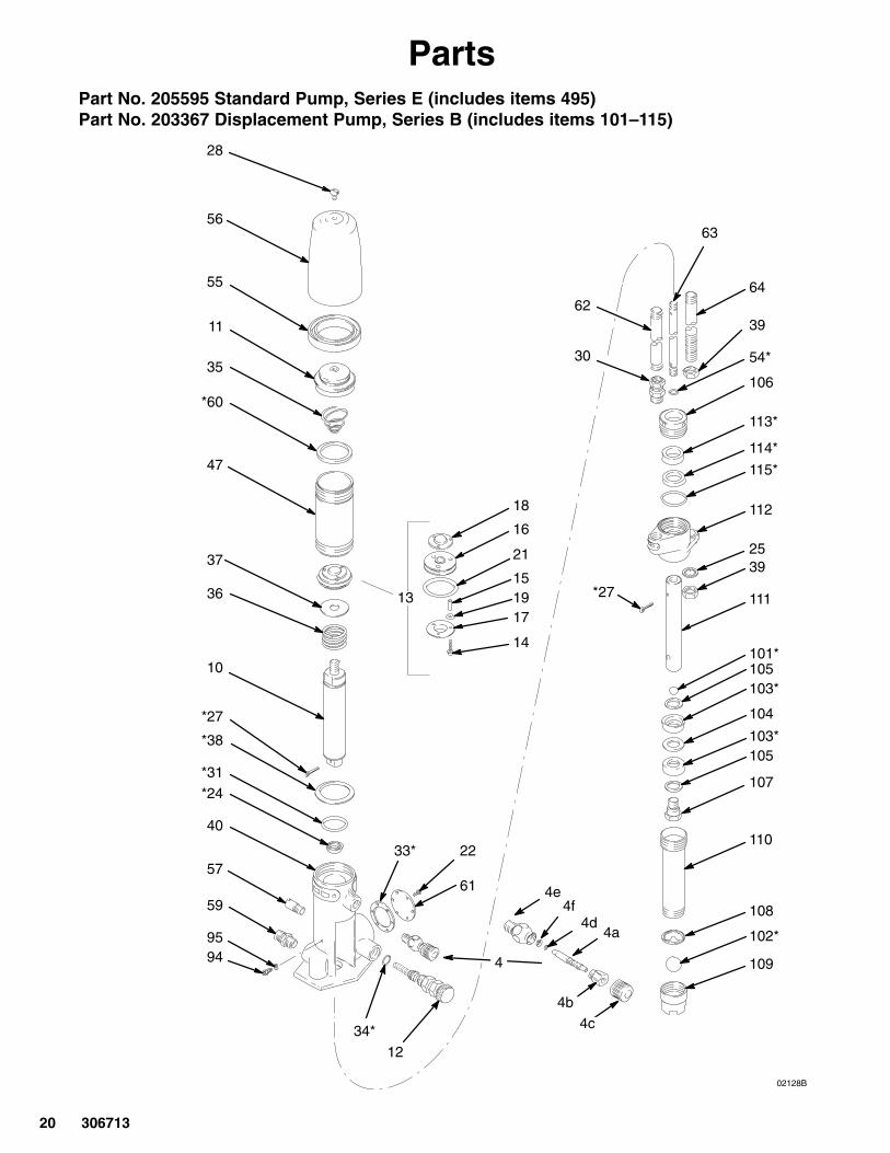
PartsPart No. 205595 Standard Pump, Series E (includes items 495)Part No. 203367 Displacement Pump, Series B (includes items 101–115)
306713 21
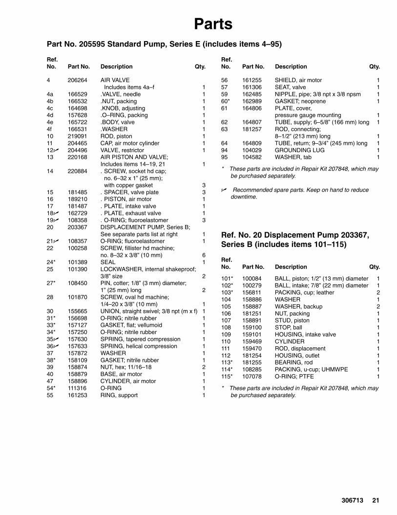
PartsPart No. 205595 Standard Pump, Series E (includes items 4–95)
Ref.No. Part No. Description Qty.
Ref.No. Part No. Description Qty.
4 206264 AIR VALVEIncludes items 4a–f 1
4a 166529 .VALVE, needle 14b 166532 .NUT, packing 14c 164698 .KNOB, adjusting 14d 157628 .O–RING, packing 14e 165722 .BODY, valve 14f 166531 .WASHER 110 219091 ROD, piston 111 204465 CAP, air motor cylinder 112� 204496 VALVE, restrictor 113 220168 AIR PISTON AND VALVE;
Includes items 14–19, 21 114 220884 . SCREW, socket hd cap;
no. 6–32 x 1” (25 mm);with copper gasket 3
15 181485 . SPACER, valve plate 316 189210 . PISTON, air motor 117 181487 . PLATE, intake valve 118� 162729 . PLATE, exhaust valve 119� 108358 . O-RING; fluoroelastomer 320 203367 DISPLACEMENT PUMP, Series B;
See separate parts list at right 121� 108357 O-RING; fluoroelastomer 122 100258 SCREW, fillister hd machine;
no. 8–32 x 3/8” (10 mm) 624* 101389 SEAL 125 101390 LOCKWASHER, internal shakeproof;
3/8” size 227* 108450 PIN, cotter; 1/8” (3 mm) diameter;
1” (25 mm) long 228 101870 SCREW, oval hd machine;
1/4–20 x 3/8” (10 mm) 130 155665 UNION, straight swivel; 3/8 npt (m x f) 131* 156698 O-RING; nitrile rubber 133* 157127 GASKET, flat; vellumoid 134* 157250 O-RING; nitrile rubber 135� 157630 SPRING, tapered compression 136� 157633 SPRING, helical compression 137 157872 WASHER 138* 158109 GASKET; nitrile rubber 139 158874 NUT, hex; 11/16–18 240 158879 BASE, air motor 147 158896 CYLINDER, air motor 154* 111316 O-RING 155 161253 RING, support 1
56 161255 SHIELD, air motor 157 161306 SEAT, valve 159 162485 NIPPLE, pipe; 3/8 npt x 3/8 npsm 160* 162989 GASKET; neoprene 161 164806 PLATE, cover,
pressure gauge mounting 162 164807 TUBE, supply; 6–5/8” (166 mm) long 163 181257 ROD, connecting;
8–1/2” (213 mm) long 164 164809 TUBE, return; 9–3/4” (245 mm) long 194 104029 GROUNDING LUG 195 104582 WASHER, tab 1
* These parts are included in Repair Kit 207848, which maybe purchased separately.
� Recommended spare parts. Keep on hand to reducedowntime.
Ref. No. 20 Displacement Pump 203367,Series B (includes items 101–115)
Ref.No. Part No. Description Qty.
101* 100084 BALL, piston; 1/2” (13 mm) diameter 1102* 100279 BALL, intake; 7/8” (22 mm) diameter 1103* 156811 PACKING, cup; leather 2104 158886 WASHER 1105 158887 WASHER, backup 2106 181251 NUT, packing 1107 158891 STUD, piston 1108 159100 STOP, ball 1109 159101 HOUSING, intake valve 1110 159469 CYLINDER 1111 159470 ROD, displacement 1112 181254 HOUSING, outlet 1113* 181255 BEARING, rod 1114* 108285 PACKING, u-cup; UHMWPE 1115* 107078 O-RING; PTFE 1
* These parts are included in Repair Kit 207848, which maybe purchased separately.

22 306713
Technical DataCategory Data
Maximum fluid working pressure 360 psi (25 bar)
Maximum air input pressure 180 psi (12 bar)
Ratio 2:1
Pump cycles per gallon (3.8 liters) 46
Fluid flow at 60 cycles per minute 1.25 gallons (4.7 liters)
Air inlet size 1/4 npsm(f)
Fluid outlet size 3/8 npsm(m)
Fluid inlet size 2 in. npt(f)
Maximum operating temperature 180�F (82�C)
* Sound level at 180 psi, 25 cycles/min 75 dBa
* Sound power level at 180 psi, 25 cycles/min
80 dBa
Wetted parts Pump: Steel, aluminum, iron, leather
* Tested in accordance with ISO 3744.
0
50
100
150
200
250
300
350
400
0.0 0.5 1.0 1.5 2.0
FLUID FLOW(TEST FLUID: 10 WEIGHT OIL)
psibar
gpmliters/min
To find Fluid Outlet Pressure (bar/psi) at a specific fluid flow (lpm/gpm)and operating air pressure (bar/psi):1. Locate desired flow along bottom of chart.2. Follow vertical line up to intersection with selected fluid outlet
pressure curve (black). Follow left to scale to read fluid outletpressure.
To find Pump Air Consumption (m�/min or scfm) at a specific fluid flow(lpm/gpm) and air pressure (bar/psi):
1. Locate desired flow along bottom of chart.
2. Read vertical line up to intersection with selected air consumptioncurve (gray). Follow right to scale to read air consumption.
cycles/min scfmm�/min
3
6
1.9
.084
0.168
18 46
3.8 5.7 7.6
3.5
10.5
74
21
14
90.252
KEY: Fluid Outlet Pressure – Black Curves A 180 psi (12.5 bar) Air PressureAir Consumption – Gray Curves B 100 psi (7 bar) Air Pressure
C 70 psi (4.9 bar) Air PressureD 40 psi (2.8 bar) Air Pressure
A
B
C
A
B
C7
17.5
24.5
28
60120.336
D
D

306713 23
Dimensions
02120
Model 205585 Shown
A
B
Pump Model A B Weight
205585 29 in. (737 mm) 13 in. (330 mm) 12.7 kg (28 lb)
205584 29 in. (737 mm) 13 in. (330 mm) 11.8 kg (26 lb)
24 306713
Graco Standard WarrantyWARRANTY
Graco warrants all equipment listed in this manual which is manufactured by Graco and bearing its name to be free from defectsin material and workmanship on the date of sale to the original purchaser for use. Graco will, for a period of twelve months fromthe date of sale, repair or replace any part of the equipment determined by Graco to be defective. This warranty applies onlywhen the equipment is installed, operated and maintained in accordance with Graco’s written recommendations.
This warranty does not cover, and Graco shall not be liable for general wear and tear, or any malfunction, damage or wearcaused by faulty installation, misapplication, abrasion, corrosion, inadequate or improper maintenance, negligence, accident,tampering, or substitution of non-Graco component parts. Nor shall Graco be liable for malfunction, damage or wear caused bythe incompatibility of Graco equipment with structures, accessories, equipment or materials not supplied by Graco, or the im-proper design, manufacture, installation, operation or maintenance of structures, accessories, equipment or materials not sup-plied by Graco.
This warranty is conditioned upon the prepaid return of the equipment claimed to be defective to an authorized Graco distributorfor verification of the claimed defect. If the claimed defect is verified, Graco will repair or replace free of charge any defectiveparts. The equipment will be returned to the original purchaser transportation prepaid. If inspection of the equipment does notdisclose any defect in material or workmanship, repairs will be made at a reasonable charge, which charges may include thecosts of parts, labor, and transportation.
THIS WARRANTY IS EXCLUSIVE, AND IS IN LIEU OF ANY OTHER WARRANTIES, EXPRESS OR IMPLIED, INCLUDINGBUT NOT LIMITED TO WARRANTY OF MERCHANTABILITY OR WARRANTY OF FITNESS FOR A PARTICULAR PUR-POSE.
Graco’s sole obligation and buyer’s sole remedy for any breach of warranty shall be as set forth above. The buyer agrees that noother remedy (including, but not limited to, incidental or consequential damages for lost profits, lost sales, injury to person or prop-erty, or any other incidental or consequential loss) shall be available. Any action for breach of warranty must be brought within two(2) years of the date of sale.
GRACO MAKES NO WARRANTY, AND DISCLAIMS ALL IMPLIED WARRANTIES OF MERCHANTABILITY AND FITNESSFOR A PARTICULAR PURPOSE IN CONNECTION WITH ACCESSORIES, EQUIPMENT, MATERIALS, OR COMPONENTSSOLD BUT NOT MANUFACTURED BY GRACO. These items sold, but not manufactured by Graco (such as electric motors,switches, hose, etc.) are subject to the warranty, if any, of their manufacturer. Graco will provide purchaser with reasonable assis-tance in making any claim for breach of these warranties.
For Sales to Canadian Customers:
Except as expressly stated herein, Graco makers no representations, warranties or conditions, express, implied or collateral, con-cerning any goods or services sold, and GRACO SHALL NOT BE LIABLE IN ANY MANNER FOR any other representation,warranty or condition of any kind, whether arising by operation of law or otherwise, including but not limited to, WARRANTIES OFMERCHANTABLE QUALITY OR FITNESS FOR A PARTICULAR PURPOSE.
LIMITATION OF LIABILITY
In no event will Graco be liable for indirect, incidental, special or consequential damages resulting from Graco supplying equip-ment hereunder, or for the furnishing, performance, or use of any products or other goods sold hereto, whether due to a breach ofcontract, breach of warranty, the negligence of Graco, or otherwise.
Graco InformationTO PLACE AN ORDER, contact your Graco distributor, or call one of the following numbers
to identify the distributor closest to you: 1–800–328–0211 Toll Free
612–623–6921612–378–3505 Fax
All written and visual data contained in this document reflects the latest product information available at the time of publication. Graco reserves the right to make changes at any time without notice.
This manual contains English. MM 306713
Graco Headquarters: MinneapolisInternational Offices: Belgium, China, Japan, Korea
GRACO INC. P.O. BOX 1441 MINNEAPOLIS, MN 55440–1441Copyright 1961, Graco Inc. is registered to ISO 9001
www.graco.comRevised 03/2009