owner's manual - fimco industriesfm1296).pdfmodel: lg-2500-303 (5301065) (25 gallon lawn &...
TRANSCRIPT
Warranty/Parts/ServiceFor home usage, products are warranted for one year from date of purchase against manufacturer or workmanship defects.
Commercial users have a 90 day warranty.
Your authorized dealer is the best source of replacement parts and service. To obtain prompt, efficient service, always remember to give the following information...
- Correct Part Description and/or part number. - Model number/Serial number of your sprayer.
Part descriptions and part numbers can be obtained from the illustrated parts list section(s) of this manual.
Whenever you need parts or repair service, contact your distributor/dealer first. For warranty work, always take your original sales slip, or other evidence of purchase date, to your distributor/dealer.
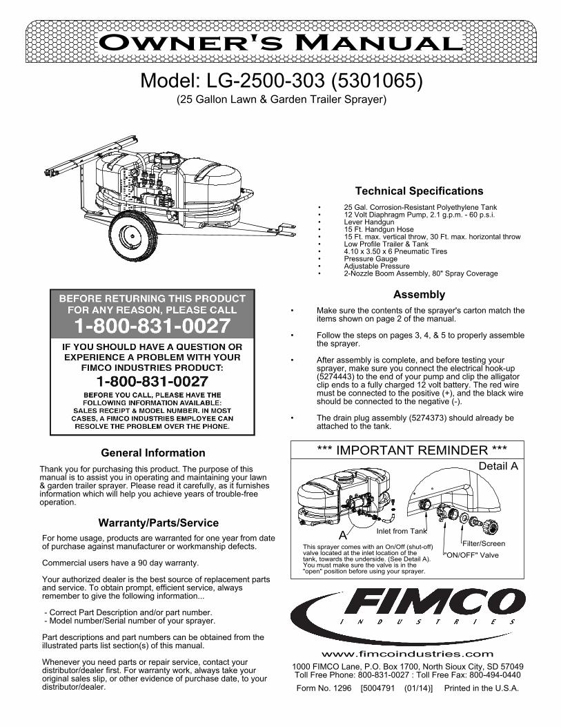
"ON/OFF" Valve
*** IMPORTANT REMINDER ***
A Inlet from Tank
Filter/Screen
Detail A
"open" position before using your sprayer.You must make sure the valve is in thetank, towards the underside. (See Detail A).valve located at the inlet location of theThis sprayer comes with an On/Off (shut-off)
25 Gal. Corrosion-Resistant Polyethylene Tank•12 Volt Diaphragm Pump, 2.1 g.p.m. - 60 p.s.i.•Lever Handgun•15 Ft. Handgun Hose•15 Ft. max. vertical throw, 30 Ft. max. horizontal throw•Low Profile Trailer & Tank•4.10 x 3.50 x 6 Pneumatic Tires•Pressure Gauge•Adjustable Pressure•2-Nozzle Boom Assembly, 80" Spray Coverage•
Technical Specifications
Form No. 1296 [5004791 (01/14)] Printed in the U.S.A.
Model: LG-2500-303 (5301065)(25 Gallon Lawn & Garden Trailer Sprayer)
Owner's Manual
Assembly
General InformationThank you for purchasing this product. The purpose of this manual is to assist you in operating and maintaining your lawn & garden trailer sprayer. Please read it carefully, as it furnishes information which will help you achieve years of trouble-free operation.
1000 FIMCO Lane, P.O. Box 1700, North Sioux City, SD 57049Toll Free Phone: 800-831-0027 : Toll Free Fax: 800-494-0440
www.fimcoindustries.com
Make sure the contents of the sprayer's carton match the •items shown on page 2 of the manual.
Follow the steps on pages 3, 4, & 5 to properly assemble •the sprayer.
After assembly is complete, and before testing your •sprayer, make sure you connect the electrical hook-up (5274443) to the end of your pump and clip the alligator clip ends to a fully charged 12 volt battery. The red wire must be connected to the positive (+), and the black wire should be connected to the negative (-).
The drain plug assembly (5274373) should already be •attached to the tank.
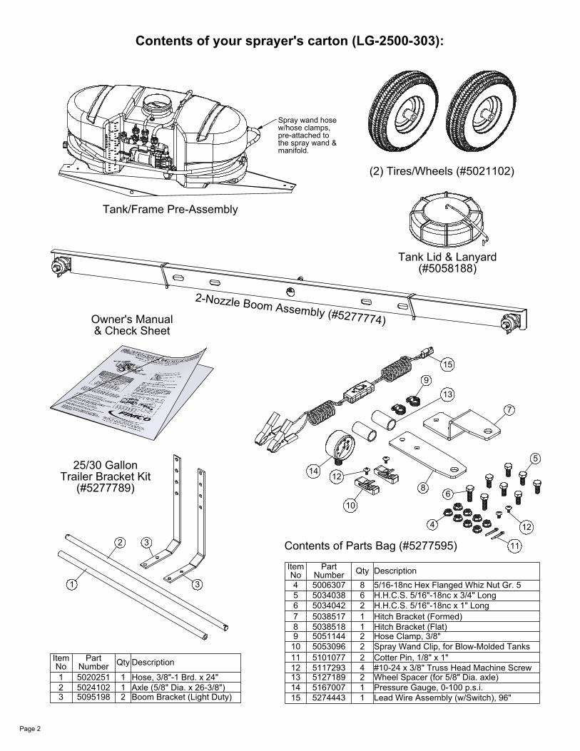
Tank/Frame Pre-Assembly
Spray wand hose w/hose clamps, pre-attached to the spray wand & manifold.
(2) Tires/Wheels (#5021102)
2-Nozzle Boom Assembly (#5277774)
2
1 3
3
25/30 GallonTrailer Bracket Kit
(#5277789)
Tank Lid & Lanyard(#5058188)
15
13
9
8
7
14 12
10
12
11
5
4
6
Contents of Parts Bag (#5277595)
Owner's Manual & Check Sheet
Page 2
Contents of your sprayer's carton (LG-2500-303):
Item No
Part Number Qty Description
1 5020251 1 Hose, 3/8"-1 Brd. x 24"2 5024102 1 Axle (5/8" Dia. x 26-3/8")3 5095198 2 Boom Bracket (Light Duty)
Item No
Part Number Qty Description
4 5006307 8 5/16-18nc Hex Flanged Whiz Nut Gr. 55 5034038 6 H.H.C.S. 5/16"-18nc x 3/4" Long6 5034042 2 H.H.C.S. 5/16"-18nc x 1" Long7 5038517 1 Hitch Bracket (Formed)8 5038518 1 Hitch Bracket (Flat)9 5051144 2 Hose Clamp, 3/8"
10 5053096 2 Spray Wand Clip, for Blow-Molded Tanks11 5101077 2 Cotter Pin, 1/8" x 1"12 5117293 4 #10-24 x 3/8" Truss Head Machine Screw13 5127189 2 Wheel Spacer (for 5/8" Dia. axle)14 5167007 1 Pressure Gauge, 0-100 p.s.i.15 5274443 1 Lead Wire Assembly (w/Switch), 96"
5034042
5038517
5038518
5006307
5021102
5127189
5021102
Valve stem facing outward
5127189
5024102
51010775021102
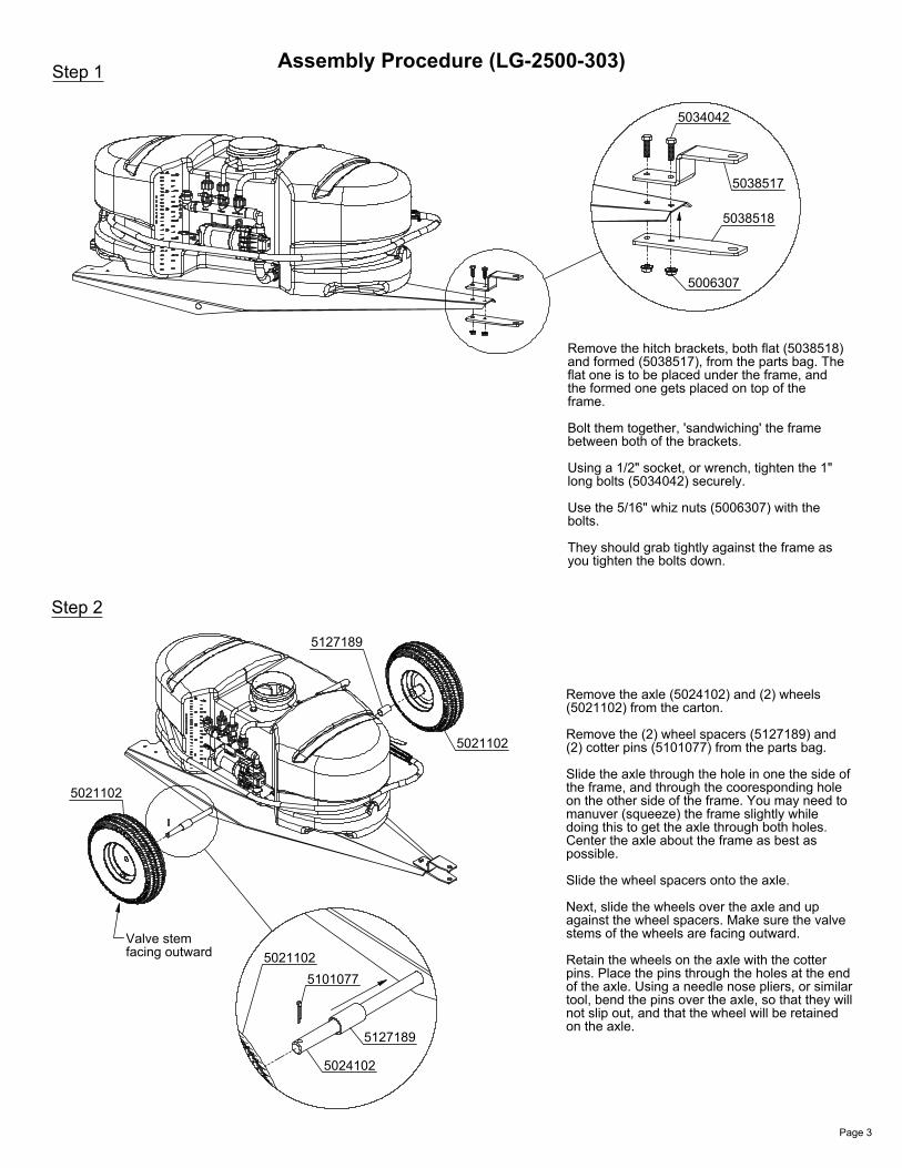
Remove the hitch brackets, both flat (5038518) and formed (5038517), from the parts bag. The flat one is to be placed under the frame, and the formed one gets placed on top of the frame.
Bolt them together, 'sandwiching' the frame between both of the brackets.
Using a 1/2" socket, or wrench, tighten the 1" long bolts (5034042) securely.
Use the 5/16" whiz nuts (5006307) with the bolts.
They should grab tightly against the frame as you tighten the bolts down.
Page 3
Step 1 Assembly Procedure (LG-2500-303)
Remove the axle (5024102) and (2) wheels (5021102) from the carton.
Remove the (2) wheel spacers (5127189) and (2) cotter pins (5101077) from the parts bag.
Slide the axle through the hole in one the side of the frame, and through the cooresponding hole on the other side of the frame. You may need to manuver (squeeze) the frame slightly while doing this to get the axle through both holes. Center the axle about the frame as best as possible.
Slide the wheel spacers onto the axle.
Next, slide the wheels over the axle and up against the wheel spacers. Make sure the valve stems of the wheels are facing outward.
Retain the wheels on the axle with the cotter pins. Place the pins through the holes at the end of the axle. Using a needle nose pliers, or similar tool, bend the pins over the axle, so that they will not slip out, and that the wheel will be retained on the axle.
Step 2
509519850951985034038
5095198
5006307
5006307
5034038
5095198
52777745095198
5034038
5006307
5051144
5020251
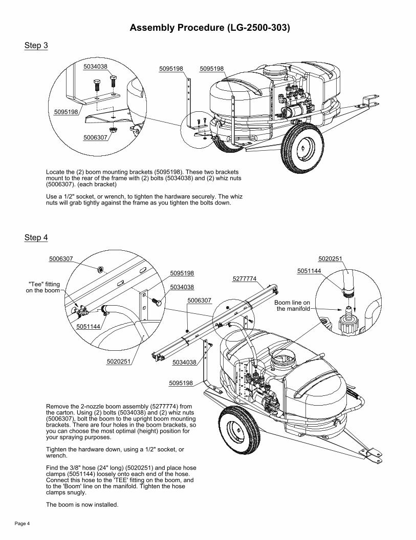
"Tee" fitting on the boom
5051144
5020251
Boom line on the manifold
Page 4
Step 3
Assembly Procedure (LG-2500-303)
Locate the (2) boom mounting brackets (5095198). These two brackets mount to the rear of the frame with (2) bolts (5034038) and (2) whiz nuts (5006307). (each bracket)
Use a 1/2" socket, or wrench, to tighten the hardware securely. The whiz nuts will grab tightly against the frame as you tighten the bolts down.
Step 4
Remove the 2-nozzle boom assembly (5277774) from the carton. Using (2) bolts (5034038) and (2) whiz nuts (5006307), bolt the boom to the upright boom mounting brackets. There are four holes in the boom brackets, so you can choose the most optimal (height) position for your spraying purposes.
Tighten the hardware down, using a 1/2" socket, or wrench.
Find the 3/8" hose (24" long) (5020251) and place hose clamps (5051144) loosely onto each end of the hose. Connect this hose to the 'TEE' fitting on the boom, and to the 'Boom' line on the manifold. Tighten the hose clamps snugly.
The boom is now installed.
5167007
Connection at the manifold
Tab on tank for lid lanyard
5058188
5117293
5053096
5163100
Page 5
Assembly Procedure (LG-2500-303)
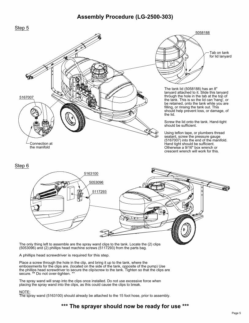
Step 5
The tank lid (5058188) has an 8" lanyard attached to it. Slide this lanyard through the hole in the tab at the top of the tank. This is so the lid can 'hang', or be retained, onto the tank while you are filling, or rinsing the tank out. This should help prevent loss, or damage, of the lid.
Screw the lid onto the tank. Hand-tight should be sufficient.
Using teflon tape, or plumbers thread sealant, screw the pressure gauge (5167007) into the end of the manifold. Hand tight should be sufficient. Otherwise a 9/16" box wrench or crescent wrench will work for this.
*** The sprayer should now be ready for use ***
Step 6
The only thing left to assemble are the spray wand clips to the tank. Locate the (2) clips (5053096) and (2) phillips head machine screws (5117293) from the parts bag.
A phillips head screwdriver is required for this step.
Place a screw through the hole in the clip, and bring it up to the tank, where the embossments for the clips are. (located on the side of the tank, opposite of the pump) Use the phillips head screwdriver to secure the clip/screw to the tank. Tighten so that the clips are secure. ** Do not over-tighten. **
The spray wand will snap into the clips once installed. Do not use excessive force when placing the spray wand into the clips, as this could cause the clips to break.
NOTE:The spray wand (5163100) should already be attached to the 15 foot hose, prior to assembly.
Time Required in seconds to travel a distance of:
200 Ft.(Miles per Hour) 100 Ft.
2.03.0
1.0
5.06.07.0
9.08.0
10.0
4.0
157.66.8 14
68 sec.
17
8.59.71114
3423
34
17192327
136 sec.6845
Speed in M.P.H.
Speed Chart
300 Ft.
2320
51
3441
2926
68102
205 sec.
3
3026
3
20.914.9MPH
.34
.48
3
.059
.048
.034MPH
.688
.596
MPH
Gallons Per 100 Sq. Ft. - Based on Water
Gallons Per 1000 Sq. Ft. - Based on Water
Gallons Per Acre - Based on Water
.068
Height
Height
3(Gray)
No.Tip
(Gray)3
No.Tip
.072.142018" .42
.60
.523040 .206
.174 .087.10
.30
(GPM)Capacity
.60
.52
.42
.30
(GPM)Capacity
40
10
(psi)PressureSpray
(psi)Pressure
302010
18"
Spray
1.002.06
MPH1
.10
2 MPH.05
MPH
1.41.74
1.01
1
.50
.87
.72
2 MPH
HeightNo.
3(Gray)
(Color)
Tip
.60
.52
.42
.30
(GPM)Capacity
(psi)
40302010
18"
PressureSpray2 1
MPH
63
9076
4431.5
4538
MPH22
.019 .014.029.036
.023
.027.044.05
.035.04
.017.02
7.5
.135
.27.236.19
MPH7.5
.013
MPH
.408.50
4
.025MPH
5 MPH.02
.254.36.44
MPH4
.204.29.35
MPH5
.20
10
.01MPH
.176.14.103
10 MPH
MPH7.5
8.4
11.810.3
5.9
5 4
15.719.322
MPH11.1
12.6
17.815.4
MPH8.9
10
6.3
8.97.7
MPH4.5
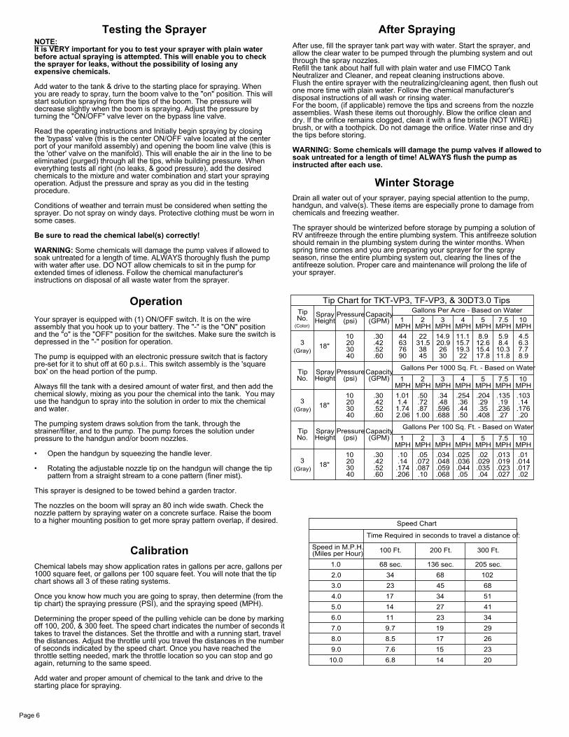
Tip Chart for TKT-VP3, TF-VP3, & 30DT3.0 Tips
Page 6
CalibrationChemical labels may show application rates in gallons per acre, gallons per 1000 square feet, or gallons per 100 square feet. You will note that the tip chart shows all 3 of these rating systems.
Once you know how much you are going to spray, then determine (from the tip chart) the spraying pressure (PSI), and the spraying speed (MPH).
Determining the proper speed of the pulling vehicle can be done by marking off 100, 200, & 300 feet. The speed chart indicates the number of seconds it takes to travel the distances. Set the throttle and with a running start, travel the distances. Adjust the throttle until you travel the distances in the number of seconds indicated by the speed chart. Once you have reached the throttle setting needed, mark the throttle location so you can stop and go again, returning to the same speed.
Add water and proper amount of chemical to the tank and drive to the starting place for spraying.
Testing the SprayerNOTE:It is VERY important for you to test your sprayer with plain water before actual spraying is attempted. This will enable you to check the sprayer for leaks, without the possibility of losing any expensive chemicals.
Add water to the tank & drive to the starting place for spraying. When you are ready to spray, turn the boom valve to the "on" position. This will start solution spraying from the tips of the boom. The pressure will decrease slightly when the boom is spraying. Adjust the pressure by turning the "ON/OFF" valve lever on the bypass line valve.
Read the operating instructions and Initially begin spraying by closing the 'bypass' valve (this is the center ON/OFF valve located at the center port of your manifold assembly) and opening the boom line valve (this is the 'other' valve on the manifold). This will enable the air in the line to be eliminated (purged) through all the tips, while building pressure. When everything tests all right (no leaks, & good pressure), add the desired chemicals to the mixture and water combination and start your spraying operation. Adjust the pressure and spray as you did in the testing procedure.
Conditions of weather and terrain must be considered when setting the sprayer. Do not spray on windy days. Protective clothing must be worn in some cases.
Be sure to read the chemical label(s) correctly!
WARNING: Some chemicals will damage the pump valves if allowed to soak untreated for a length of time. ALWAYS thoroughly flush the pump with water after use. DO NOT allow chemicals to sit in the pump for extended times of idleness. Follow the chemical manufacturer's instructions on disposal of all waste water from the sprayer.
OperationYour sprayer is equipped with (1) ON/OFF switch. It is on the wire assembly that you hook up to your battery. The "-" is the "ON" position and the "o" is the "OFF" position for the switches. Make sure the switch is depressed in the "-" position for operation.
The pump is equipped with an electronic pressure switch that is factory pre-set for it to shut off at 60 p.s.i.. This switch assembly is the 'square box' on the head portion of the pump.
Always fill the tank with a desired amount of water first, and then add the chemical slowly, mixing as you pour the chemical into the tank. You may use the handgun to spray into the solution in order to mix the chemical and water.
The pumping system draws solution from the tank, through the strainer/filter, and to the pump. The pump forces the solution under pressure to the handgun and/or boom nozzles.
Open the handgun by squeezing the handle lever.•
Rotating the adjustable nozzle tip on the handgun will change the tip •pattern from a straight stream to a cone pattern (finer mist).
This sprayer is designed to be towed behind a garden tractor.
The nozzles on the boom will spray an 80 inch wide swath. Check the nozzle pattern by spraying water on a concrete surface. Raise the boom to a higher mounting position to get more spray pattern overlap, if desired.
After use, fill the sprayer tank part way with water. Start the sprayer, and allow the clear water to be pumped through the plumbing system and out through the spray nozzles.Refill the tank about half full with plain water and use FIMCO Tank Neutralizer and Cleaner, and repeat cleaning instructions above.Flush the entire sprayer with the neutralizing/cleaning agent, then flush out one more time with plain water. Follow the chemical manufacturer's disposal instructions of all wash or rinsing water.For the boom, (if applicable) remove the tips and screens from the nozzle assemblies. Wash these items out thoroughly. Blow the orifice clean and dry. If the orifice remains clogged, clean it with a fine bristle (NOT WIRE) brush, or with a toothpick. Do not damage the orifice. Water rinse and dry the tips before storing.
WARNING: Some chemicals will damage the pump valves if allowed to soak untreated for a length of time! ALWAYS flush the pump as instructed after each use.
After Spraying
Winter StorageDrain all water out of your sprayer, paying special attention to the pump, handgun, and valve(s). These items are especially prone to damage from chemicals and freezing weather.
The sprayer should be winterized before storage by pumping a solution of RV antifreeze through the entire plumbing system. This antifreeze solution should remain in the plumbing system during the winter months. When spring time comes and you are preparing your sprayer for the spray season, rinse the entire plumbing system out, clearing the lines of the antifreeze solution. Proper care and maintenance will prolong the life of your sprayer.
527xxxx 0101000000
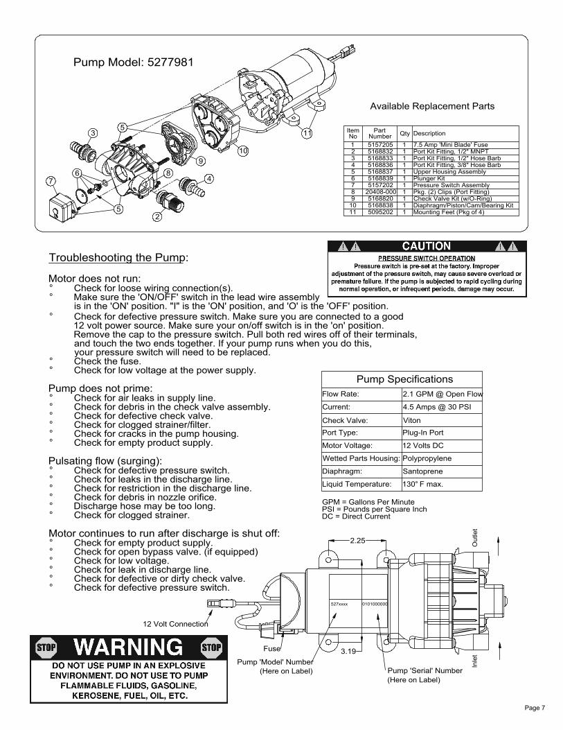
Pump Model: 5277981
Inle
tO
utle
t
Available Replacement Parts
and touch the two ends together. If your pump runs when you do this,Remove the cap to the pressure switch. Pull both red wires off of their terminals,12 volt power source. Make sure your on/off switch is in the 'on' position.Check for defective pressure switch. Make sure you are connected to a goodis in the 'ON' position. "I" is the 'ON' position, and 'O' is the 'OFF' position.Make sure the 'ON/OFF' switch in the lead wire assembly
Pump 'Model' Number
Motor continues to run after discharge is shut off:
° Check the fuse.
Check for defective pressure switch.Check for defective or dirty check valve.Check for leak in discharge line.Check for low voltage.Check for open bypass valve. (if equipped)Check for empty product supply.
Check for clogged strainer.Discharge hose may be too long.Check for debris in nozzle orifice.Check for restriction in the discharge line.Check for leaks in the discharge line.Check for defective pressure switch.
Pulsating flow (surging):
Check for empty product supply.Check for cracks in the pump housing.Check for clogged strainer/filter.Check for defective check valve.Check for debris in the check valve assembly.Check for air leaks in supply line.
Pump does not prime:
Check for low voltage at the power supply.
°
°
°
°°
°°
°
°°
°°
°
°°°
°°
°
12 Volt Connection
Fuse
Check for loose wiring connection(s).Motor does not run:
Troubleshooting the Pump:
your pressure switch will need to be replaced.
3
°
°°
76
52
89
4
10
5
Pump 'Serial' Number
4.5 Amps @ 30 PSI
2.1 GPM @ Open Flow
3.19
DC = Direct CurrentPSI = Pounds per Square InchGPM = Gallons Per Minute
Liquid Temperature:
Wetted Parts Housing:
Motor Voltage:
Pump Specifications
2.25
Diaphragm:
Port Type:Check Valve:
Current:
Flow Rate:
130 F max.°
Santoprene
Polypropylene
12 Volts DC
Plug-In PortViton
Mounting Feet (Pkg of 4)Diaphragm/Piston/Cam/Bearing KitCheck Valve Kit (w/O-Ring)Pkg. (2) Clips (Port Fitting)Pressure Switch Assembly
Upper Housing AssemblyPort Kit Fitting, 3/8" Hose BarbPort Kit Fitting, 1/2" Hose BarbPort Kit Fitting, 1/2" MNPT7.5 Amp 'Mini Blade' Fuse
11 DescriptionQtyNumberNo
509520251688385168820
20408-0005157202516883951688375168836516883351688325157205
8
11109
4
765
321
Plunger Kit
1
11
1
1
11
1
11
1
Item Part
(Here on Label)(Here on Label)
Page 7

D
Exploded View/Parts List:Model: LG-2500-303 (5301065)
2
2
8
8
8
2
8
2
30
256
911
12
2
10
16
21
7
21
25
6
22
29
32 27
23
13
15
24
31
18
4 14 14
5 14 14
35.1
35.2 35.3.2
35.3.4
35.3.2
35.4
35.2
36
1
3
19
17
28
26
41434.6
34.534.4
34.334.8
34.7
34.2
34.3
34.1
34.634.5
34.4
36
33.2
33.6
33.133.3
33.5
33.4
16
29
33.7
20
DETAIL D
35.3.3.435.3.3.3
35.3.3.5
35.3.3.235.3.3.1
Page 8
Item No Part Number Qty Description
1 5006209 1 Poly Knurled Swivel Nut, 3/4" FGHT2 5006307 8 5/16"-18 Hex Whiz (Flange) Locknut3 5016066 1 Garden Hose Washer4 5020251 1 Hose, 3/8"-1 Brd. x 24"5 5020524 1 Hose, 3/8"-1 Brd. x 15 Ft.6 5021102 2 4.10/3.50-6 Wheel (White) w/2 1/4" Offset & 5/8" BB7 5024102 1 Axle (5/8" Dia. x 26-3/8")8 5034038 6 H.H.C.S. 5/16"-18nc x 3/4" Long9 5034042 2 H.H.C.S. 5/16"-18nc x 1" Long
10 5034531 4 5/16"-18 x 5/8" Flange Lock Screw11 5038517 1 Hitch Bracket (Formed)12 5038518 1 Hitch Bracket (Flat)13 5051122 1 5/8" Black Nylon Loom Cable Clamp14 5051144 4 Hose Clamp, 3/8"15 5058188 1 Tank Lid w/Lanyard16 5070063 1 Trailer Frame (25-30 Gal) (Red)17 5075018 1 Grommet18 5095198 2 Boom Bracket (Light Duty)19 5100359 1 Poly Bypass "J" Hose (3.8/2.1 - 25 Gal.)20 5100452 1 Siphon Tube21 5101077 2 Cotter Pin, 1/8" x 1"22 5117167 3 #10-24 x 5/8" Phillips Truss Head Machine Screw23 5117234 1 #10-24 x 1/2" Phillips Truss Head Machine Screw24 5117313 1 #10-24 x 2 1/2" Truss Head Machine Screw25 5127189 2 Wheel Spacer (for 5/8" Dia. axle)26 5127191 1 Manifold Spacer (2.1gpm)27 5163100 1 Low-Flow Spray Wand w/X-26 Tip28 5167007 1 Pressure Gauge, 0-100 p.s.i.29 5169243 1 25 Gallon Tank (White/Side-Mount Pump)30 5274373 1 Drain Plug Cap, Tether, and Washer Assembly31 5274443 1 Lead Wire Assembly (w/Switch), 96"
Item No Part Number Qty Description
32 5274880 1 Handgun Clips & Screws (Pkg/2) (#10-24 Thread)33 5275877 1 Intake Sub-Assembly
33.1 5143188 1 Nylon Shut-Off Valve (3/4" GHT)33.2 5168833 1 Port Kit Fitting, 1/2" Hose Barb33.3 5116242 1 Strainer, 1" Filter Washer33.4 5149035 1 Poly Swivel, 1/2" Hose Barb33.5 5006209 1 Poly Knurled Swivel Nut, 3/4" FGHT33.6 5020497 1 1/2" Polyspring Hose x 6"33.7 5051114 2 Hose Clamp (3/8"-1/2")34 5277685 1 Manifold Assembly (Trailer/ATV)
34.1 5010430 1 Port Kit Elbow, 1/2" FNPT34.2 5143405 1 Manifold w/Mounting Tab34.3 5143188 2 Nylon Shut-Off Valve (3/4" GHT)34.4 5016066 2 Garden Hose Washer34.5 5149034 2 Poly Swivel, 3/8" Hose Barb34.6 5006209 2 Poly Knurled Swivel Nut, 3/4" FGHT34.7 5010236 1 Poly Elbow, 1/2" FNPT x 1/2" FNPT34.8 5041073 1 Poly Reducing Bushing, 1/2" MNPT x 1/4" FNPT35 5277774 1 2-Nozzle Boom (QJ)
35.1 5022431 1 Boom Mount Angle -2 Nozzle (QJ100)35.2 5053110 2 Plastic Retaining Clip (14 & 16 Ga.)35.3 5277692 1 2-Nozzle Harness (3/8")
35.3.1 5051144 4 Hose Clamp, 3/8"35.3.2 5020510 2 Hose, 3/8"-1 Brd. x 19-3/8"35.3.3 5277688 2 ELL Nozzle Sub-Assembly (3/8")
35.3.3.1 5056113 1 Single Hose Shank (3/8" Hose)35.3.3.2 5116019 1 Nozzle Strainer, Red (50 Mesh)35.3.3.3 5018274 1 Turbo FloodJet Tip (TF-VP3)35.3.3.4 5046251 1 QJ Cap Only (Black)35.3.3.5 5016157 1 Seat Washer (QJ Caps)35.3.4 5086025 1 Poly Hose Tee, 3/8" HB35.4 5133094 2 Nylon Cable Tie36 5277981 1 Gold Series 2.1 g.p.m. Pump (60 psi, 8 Amp)
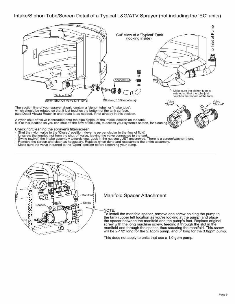
Intake/Siphon Tube/Screen Detail of a Typical L&G/ATV Sprayer (not including the 'EC' units)
to In
let o
f Pum
p
- Make sure the valve in turned to the 'Open' position before restarting your pump.- Remove the screen and clean as necessary. Replace when done and reassemble the entire assembly.- Swing (swivel) the intake assembly towards you. Look in the nut you JUST unscrewed. There is a screen/washer there.- Unscrew the knurled nut from the shut-off valve, leaving the valve connected to the tank.- Shut the nylon valve to the 'Closed' position. (lever is perpendicular to the flow of fluid)
It is at this location so you can shut off the flow of solution, to access your system's screen, for cleaning.A nylon shut-off valve is threaded onto the pipe nipple, at the intake location on the tank.
(see Detail Views) Reach in and rotate it, as needed, if not already in this position.which should be rotated so that it just touches the bottom of the tank surface.The suction line of your sprayer should contain a 'siphon tube', or 'intake tube',
Strainer, 1" Filter Washer
Knurled Nut
'Cut' View of a 'Typical' Tank
Checking/Cleaning the sprayer's filter/screen:
Nylon Shut-Off Valve (3/4" GHT)
Siphon Tube touches the bottom of the tank.rotated so that the tube justMake sure the siphon tube is
"Open"Valve
(looking inside)
"Closed"Valve
Manifold Spacer Attachment
manifold and through the spacer, thus securing the manifold. This screwscrew with the long machine screw, feeding it through the slot in thethe spacer between the manifold and the pump's foot. Replace originalthe tank (upper left location as you're looking at the pump) and placeTo install the manifold spacer, remove one screw holding the pump toNOTE:
SpacerScrew
Manifold
This does not apply to units that use a 1.0 gpm pump.
will be 2-1/2" long for the 2.1gpm pump, and 3" long for the 3.8gpm pump.
Page 9