5.15 visual resources · be reflecting the blue sky. ... in which case the visual contrast with the...
TRANSCRIPT

5.15 Visual Resources
Blythe Solar Power Project 5.15-1 August 2009
5.15 Visual Resources
This section addresses the potential impacts to visual resources of the Blythe Solar Power Project (Project). Visual resources are the elements of the landscape that contribute to the aesthetic and/or scenic character and quality of the environment. These elements are either natural or human-made. Impacts to visual resources are rated by the extent to which changes would contrast with the existing visual character and quality of the environment. This section documents the potential for the construction, operation, maintenance, and long-term presence of the Project to result in significant impacts on visual resources or sensitive receptors/key observation points.
The visual resources evaluation in this section is intended to meet both the California Energy Commission’s (CEC’s) Application for Certification (AFC) and California Environmental Quality Act (CEQA) requirements and the Bureau of Land Management’s (BLM’s) requirements to comply with the National Environmental Policy Act (NEPA). The two agencies use different visual resources analysis methodologies but in general their format, key components, and terminology of the CEC visual assessment methodology and BLM visual resource management (VRM) system are comparable. Descriptions of the characteristic landscape of the Project area and evaluation of potential visual impact thresholds are equivalent in both methods/systems. This section avoids needless duplication by integrating, to the extent practicable, the concepts and details of both the CEC’s and BLM’s methods/systems.
Summary
Project visual resources impacts are considered less than significant. During the Project construction period, construction activities and construction materials, equipment, trucks, and parked vehicles may be visible on the Project site, and along linear facility routes. These represent changes to the visual environment, but because they will be moderate in intensity and temporary in duration, impacts are considered less than significant.
The completed Project will change the visual appearance of the area, but impacts are considered less than significant. When viewed from eye level, during most hours of the day, the solar field would be relatively unobtrusive, with the power block visible above the solar field. Power block structures would have neutral colors and non-reflective surfaces to minimize their contrast with the natural background. From elevated locations, because of the movement of the sun and the changing orientation of the mirrors to track the sun’s movement, the view would change over time. In afternoon hours when viewed from distant elevated locations to the southwest, the reflective surface of the mirror would be oriented toward the viewer. At these times, on a sunny day, the solar array would create a visual impression that more closely resembles a body of water than a power plant or other industrial facility because the array would be reflecting the blue sky. On a cloudier day, the visual impression would appear grayer. In the morning hours viewed from the same elevated locations to the southwest, viewers would have the non-reflective backs of the mirrors toward them, in which case the visual contrast with the surrounding environment would be considerably less.
5.15.1 LORS Compliance The Project will comply with the applicable laws, ordinances, regulations, and standards (LORS) pertaining to visual resources. Table 5.15-1 summarizes the applicable Federal, state, and local LORS. Additional discussion of these LORS is provided following the table. Non-applicable Federal and State LORS are also discussed, and justification provided for eliminating these LORS from further evaluation.

5.15 Visual Resources
Blythe Solar Power Project 5.15-2 August 2009
Table 5.15-1 Summary of Applicable Visual Resources LORS
LORS Applicability Where Discussed in AFC
Federal:
BLM, VRM System (113 Stat. 224, Public Law 106-45-A, August 10, 1999)
BLM is responsible for ensuring that the scenic values of public lands are considered before allowing uses that may have negative visual impacts.
Section 5.15.3
Federal Land Policy and Management Act (FLPMA)
FLPMA is the enabling legislation establishing the BLM’s responsibilities for lands under its jurisdiction.
Section 5.15.1
California Desert Conservation Area (CDCA) Plan
Northern and Eastern Colorado Desert Coordinated Management (NECO) Plan
Activities proposed for public land shall be consistent with the approved BLM Resource Management Plan(s). The relevant plan for this Project is the CDCA Plan, as amended by NECO.
Section 5.15.3
California Desert Protection Act (1994)
Establishes protection of wilderness lands, including Joshua Tree Wilderness and Palen-McCoy Wilderness, and Joshua Tree National Park.
Section 5.15.3
State:
CEQA; California Public Resources Code, Section 2100 et seq.
CEQA Guidelines require (and provide criteria for) assessment of visual resources impacts.
Sections 5.15.3 and 5.15.4
Local:
County of Riverside General Plan and Ordinances / Codes
General Plan requirements for regulation of land uses.
Section 5.15.1 (also see Section 5.7, Land Use)
5.15.1.1 Federal LORS BLM VRM System
Under FLPMA, BLM developed and applies a standard visual assessment methodology, known as the VRM System, to inventory and manage scenic values on lands under its jurisdiction. Guidelines for applying the system are described in BLM Departmental Manual Section 8400 et seq.
Interim VRM classes were developed for this AFC, as called for in BLM Departmental Manual Section 8410-1. Visual resource management classes are assigned through Resource Management Plans (RMPs). The assignment of visual management classes is based on the management decisions made in RMPs. The applicable RMP for the Project is the CDCA Plan. The CDCA Plan was a unique document, and does not follow the BLM RMP process. The VRM inventory and management class mapping and narratives were not prepared for the CDCA. However, a visual resource inventory was prepared by the Applicant and was submitted for review to the BLM Palm Springs Field Office.
The CDCA Plan is characterized in terms of four Multiple-Use Classes, C (wilderness and areas recommended for wilderness status), L (limited use), M (moderate use), and I (intensive use). The

5.15 Visual Resources
Blythe Solar Power Project 5.15-3 August 2009
Project site is located within Class M. However, the Recreation Element of the CDCA Plan specifies that VRM objectives and the contrast rating procedure be used to manage visual resources. BLM VRM class standards, which are important to the assessment of potential Project impacts, are:
VRM Class I: Preserve the existing character of the landscape. This class provides for natural ecological changes; however, it does not preclude very limited management activity. The level of change to the characteristic landscape should be very low and must not attract attention.
VRM Class II: Retain the existing character of the landscape. The level of change to the characteristic landscape should be low. Management activities may be seen but should not attract the attention of the casual observer. Any changes must repeat the basic elements of form, line, color, and texture found in the predominant natural features of the characteristic landscape.
VRM Class III: Partially retain the existing character of the landscape. The level of change to the characteristic landscape should be moderate. Management activities may attract attention but should not dominate the view of the casual observer. Changes should repeat the basic elements found in the predominant natural features of the characteristic landscape.
VRM Class IV: Provide for management activities that require major modification of the existing character of the landscape. The level of change to the characteristic landscape can be high. These management activities may dominate the view and be the major focus of viewer attention. Every attempt should be made to minimize the impact of these activities through careful location, minimal disturbance, and repeating the basic elements.
FLPMA and Federal Regulations Pertaining to Right-of-Ways
Construction, operation, and maintenance of utility facilities within BLM jurisdiction require a BLM Right-of-Way (ROW) grant. A ROW grant is an authorization to use a specific piece of public land for a specific project, such as roads, pipelines, transmission lines, power plants, and communication sites.
Section 102 (a) of FLPMA states that “...the public lands are to be managed in a manner that will protect the quality of scientific, scenic, historical, ecological, environmental, air and atmospheric, water resource, and archeological values….“ Section 103(c) identifies “scenic values” as one of the resources for which public land should be managed. Section 201(a) states that “the Secretary shall prepare and maintain on a continuing basis an inventory of all public lands and their resources and other values (including scenic values)...” Section 505(a) requires that “each ROW shall contain terms and conditions which will...minimize damage to the scenic and esthetic values....”
CDCA Plan and the NECO Desert Coordination Management Plan
Under FLPMA, BLM manages the Project site pursuant to the CDCA Plan, as amended by the NECO Plan in 2002. The CDCA Plan specifies that new gas, electric, and water transmission facilities and cables for interstate communication be allowed only within appropriately designated corridors. A utility corridor 3-4 miles wide runs the length of U.S. Interstate 10 (I-10) in Riverside County. The Project site is partly within this utility corridor. The Project site is designated as BLM land use Class M (Moderate). This class prescribes a controlled balance between higher intensity use and protection of public lands, and provides for a wide variety of present and future uses such as mining, livestock grazing, recreation, energy, and utility development.
Of direct relevance to the Project visual resources analysis, the Recreation Element of the CDCA Plan specifies that visual resource management objectives and the contrast rating procedure be used to manage visual resources.

5.15 Visual Resources
Blythe Solar Power Project 5.15-4 August 2009
5.15.1.2 State LORS CEQA: California Public Resources Code, Section 2100 et seq.
CEQA includes the aesthetic environment as one of the resource areas to be considered in environmental assessment documents. Appendix G of the CEQA guidelines includes several criteria for determining whether a project may have a significant effect on the environment because of aesthetic impacts. These criteria and how they are applied, are discussed in Section 5.15.3, Environmental Impacts below. As the CEC licensing process is a CEQA-equivalent process, the CEC is the administering agency.
California Scenic Highway Program
The California Legislature initiated the California Scenic Highway Program (Streets and Highways Code Sec. 260 et seq.) in 1963, with the goal of preserving and protecting the State’s scenic highway corridors from change that would diminish their aesthetic value. The State Scenic Highway System consists of eligible and officially designated routes. A highway may be identified as eligible for listing as a State scenic highway if it offers travelers scenic views of the natural landscape, largely undisrupted by development. Eligible routes advance to officially designated status when the local jurisdiction adopts ordinances to establish a scenic corridor protection program and receives approval from the California Department of Transportation (Caltrans). Caltrans stresses the need for citizen participation in developing the guidelines that implement these requirements. Scenic corridor protection programs are required to provide for:
• Regulation of land use and development within the scenic corridor;
• Detailed land and site planning;
• Careful attention to and control of earthmoving and landscaping activity;
• Careful attention to design and appearance of structures and equipment; and
• Control of outdoor advertising, including a ban on billboards.
I-10 is not a State- or county-designated scenic highway; therefore, this regulation is not applicable to the Project. However, I-10 has been identified by the County of Riverside as eligible for designation as a scenic corridor. Riverside County’s scenic corridor policy is further described in Section 5.15.1.3, Local LORS.
5.15.1.3 Local LORS County of Riverside General Plan
The County of Riverside General Plan consists of a vision statement and the following related (to visual resources) elements: Land Use, Circulation, and Multi-purpose Open Space. It identifies County policies and implementation measures for private and public development.
The Project is located within the Eastern Riverside County Desert Area in unincorporated Riverside County. All land within the Project vicinity is designated Open Space Rural. Open Space Rural allows for a wide range of uses providing that scenic resources and views are protected. Applicable policies for County of Riverside properties designated as Open Space-Rural are summarized immediately below:
• Require that structures be designed to maintain the environmental character in which they are located.
• Require that development be designed to blend with undeveloped natural contours of the site and avoid an unvaried, unnatural, or manufactured appearance.

5.15 Visual Resources
Blythe Solar Power Project 5.15-5 August 2009
• Ensure that development does not adversely impact the open space and rural character of the surrounding area.
Policies related to Open Space, Habitat and Natural Resources Preservation are as follows:
• Provide for permanent preservation of open space lands that contain important natural resources, hazards, water features, watercourses, and scenic and recreational values.
• Require that development protect environmental resources by compliance with the Multipurpose Open Space Element of the General Plan and Federal and state regulations such as CEQA, NEPA, the Clean Air Act, and the Clean Water Act.
• Allow development clustering and/or density transfers in order to preserve open space, natural resources, and/or biologically sensitive resources.
Policies related to Project Design include:
• Require that public facilities be designed to consider their surroundings and visually enhance, not degrade the character of the surrounding area.
Scenic Corridors
The NECO Plan has not designated any scenic resources in the Project vicinity. I-10 is not a State- or county-designated scenic highway; however, it has been identified by the County of Riverside in its Circulation Element as eligible for designation as a scenic corridor. The County has indicated in its General Plan Land Use Element that I-10 should be designated a scenic highway and has developed General Plan scenic corridor policies. These policies seek to maintain resources in corridors along scenic highways. Policies for Scenic Corridors Include:
• Preserve and protect outstanding scenic vistas and visual features for the enjoyment of the traveling public.
• Incorporate riding, hiking, and bicycle trails and other compatible public recreational facilities within scenic corridors.
• Ensure that the design and appearance of new landscaping, structures, equipment, signs, or grading within Designated and Eligible State and County Scenic Highway corridors are compatible with the surrounding scenic setting or environment.
• Maintain at least a 50-foot setback from the edge of the ROW for new development adjacent to designated and eligible state and County Scenic Highways.
• Require new or relocated electric or communication distribution lines, which would be visible from Designated and Eligible State and County Scenic Highways, to be placed underground.
• Prohibit offsite outdoor advertising displays that are visible from Designated and Eligible State and County Scenic Highways.
• Require that the size, height, and type of on-premise signs visible from Designated and Eligible State and County Scenic Highways be the minimum necessary for identification. The design, materials, color, and location of the signs shall blend with the environment, utilizing natural materials where possible.
• Avoid the blocking of public views by solid walls.
County of Riverside Code and Zoning Ordinance
The County of Riverside Code was adopted pursuant to California Government Code Section 65400 et seq. The Riverside County Code includes regulations and procedures for building, grading, and

5.15 Visual Resources
Blythe Solar Power Project 5.15-6 August 2009
alteration of natural floodplains; provisions for issuance of building and grading permits, grading plans, and zoning requirements; and standards and procedures for building review. The County Zoning Ordinance describes all zoning and includes guidance for technical amendments, entitlements and policy amendments for foundation component amendments and General Plan amendments.
5.15.1.4 Agencies and Agency Contacts The local agency involved in visual resources issues is the Kern County Planning Department. Contact information is provided in Table 5.15-2.
Table 5.15-2 Agency Contact List
Agency Contact Phone/E-mail Permit/issue
Greg Hill, NEPA Specialist BLM Palm Springs 1201 Bird Center Drive Palm Springs, CA 92262
(760) 251-4850
Visual Resources and Interim Visual Resource Management Classes
Holly Roberts Associate Field Manager BLM Palm Springs Field Office 1201 Bird Center Drive Palm Springs, CA 92262
(760) 833-7100
[email protected] Application
Ron Goldman Planning Director Riverside County Planning Department38686 El Cerrito Road Palm Desert, CA 92211
(951) 955-3265
Compatibility with county land use requirements (zoning, land use plans and policies)
5.15.1.5 Required Permits and Permit Schedule No permits are required that are specific to visual resources, beyond review and approval by the BLM, CEC, and County of Riverside as part of their specific permitting requirements.
5.15.2 Affected Environment The following subsections discuss the visual environment of the Project site and its surroundings.
5.15.2.1 Characteristic Landscape Setting The Project is located in the Colorado Desert in the Great Basin section of the Basin and Range Physiographic Province (Fenneman, 1931). The desert scrub and desert dry wash woodland landscapes are comprised largely of Sonoran creosote bush and species typical of the riparian shrub woodland community, respectively. The landscape is predominantly intact on the broad Palo Verde Mesa, approximate elevation 800 feet. The mesa is visually dominated on the west by the steeply rising, barren-sloped McCoy Mountains (elevation to 2,830 feet). Mountain ranges to the north and east include the Little Maria Mountains and Big Maria Mountains.
Project construction and operation will disturb approximately 7,030 acres, within which all Project facilities will be located (as well as access roads, and rerouted drainage channels) on a site situated on a mesa approximately 7.0 miles northwest of, and above, the City of Blythe (located at a lower elevation in the

5.15 Visual Resources
Blythe Solar Power Project 5.15-7 August 2009
Palo Verde Valley) and 3.0 miles north of I-10. The Project landscape (Figure 5.15-3) is largely undeveloped with the exception of several dirt roads.
Project Viewshed
The viewshed or area of potential visual effect (the area within which the Project could potentially be seen) is shown in Figure 5.15-1. Computer-generated viewshed mapping was conducted based on the height of the proposed power block units and the ten-meter resolution (horizontal) United States Geological Survey digital elevation model.
Scenic Quality Units, Viewer Sensitivity, Distance Zones, and Interim VRM Classes
The VRM system subdivides a project area into scenic quality rating units and their associated Interim VRM classes. The boundary for the VRM area for the Project is defined by a one-mile buffer around the outside of the Project’s area of disturbance. The two landscape units consist of the mesa and uplands/mountains. Each unit represents a contiguous area with uniform landform, vegetation, visual character, and quality, as identified in the field. The project area is comprised of two scenic quality rating units. Scenic quality for rating unit #1 is determined using seven key factors as follows:
• Landform (rating 3 of possible 1 through 5 – ‘interesting erosional patterns or variety in size and shape of landforms’),
• Vegetation (rating 3 of possible 1 through 5 – ‘some variety of vegetation, but only one or two major types’),
• Water (rating 0 of possible 0 through 5 – ‘absent’),
• Color (rating 1 of possible 1 through 5 – ‘subtle color variations’),
• Adjacent scenery (rating 3 of possible 0 through 5 – ‘adjacent scenery moderately enhances overall visual quality’),
• Scarcity (rating 3 of possible 1 through 5 – ‘distinctive, though somewhat similar to others within the region’), and
• Cultural modifications (rating 0 of possible 0 through 5 – ‘modifications add little or no visual variety’).
The ratings total 13 points, which is in the Scenic Quality B category (12 – 18 points).
Scenic quality for rating unit #2 is determined using seven key factors as follows:
• Landform (rating 1 of possible 1 through 5 – ‘few or no interesting landscape features’),
• Vegetation (rating 1 of possible 1 through 5 – ‘little or no variety or contrast in vegetation’),
• Water (rating 0 of possible 0 through 5 – ‘absent’),
• Color (rating 1 of possible 1 through 5 – ‘subtle color variations’),
• Adjacent scenery (rating 3 of possible 0 through 5 – ‘adjacent scenery moderately enhances overall visual quality’),
• Scarcity (rating 1 of possible 1 through 5 – ‘this landscape is common within the region’), and
• Cultural modifications (rating 0 of possible 0 through 5 – ‘modifications add little or no visual variety’).
The ratings total 7 points, which is in the Scenic Quality C category (11 points or less).

5.15 Visual Resources
Blythe Solar Power Project 5.15-8 August 2009
Sensitivity level analysis measures public concern for scenic quality. Lands are assigned high, medium, or low sensitivity by considering the following factors:
• Types of users (Palen - McCoy Wilderness users – high, and I-10 travelers – moderate),
• Amount of use (I-10 – high),
• Public interest (McCoy Wilderness users – high and I-10 travelers - moderate),
• Adjacent land uses (low),
• Special management areas (such as Wilderness, Preserves, Areas of Critical Environmental Concern [ACEC] (high), and
• Scenery related management objectives for the area (high).
The BSPP area situated within the foreground-middleground (five miles) of the McCoy Wilderness is determined to be Sensitivity Level: High. The remaining area is determined to be Sensitivity Level: Medium, based on the number of viewers traveling I-10, and medium public interest. Key observation point (KOP) locations are determined based on user sensitivity and/or use volume.
Distance zones are indicated by the terms ‘foreground-middleground’ which refers to viewing distances of less than five miles, and ‘background’ which delineates distances between five and 15 miles. No distinction is made between foreground and middleground distances. Portions of the Project site are located within the foreground-middleground view distance zone of I-10, and the McCoy Wilderness. Remaining portions are within the background view distance zone of the Big Maria Wilderness and Little Maria Wilderness (to the north and northeast, respectively).
Interim VRM classes are categories assigned to BLM lands for two purposes: as “an inventory tool that portrays the relative value of the visual resource; and as a management tool for indicating visual resource management objectives.” There are four classes: Class I, Class II, Class III, and Class IV (Class I is the most restrictive with regard to allowable change to visual resources). Final VRM classes are assigned through the RMP development process.
Based on the combinations of scenery quality, sensitivity levels and distance zones, the Project area (including the one-mile VRM study area buffer zone) is comprised of Interim VRM II, VRM III and VRM IV classes. The VRM Class II objective is to retain the existing character of the landscape. The level of change to the characteristic landscape should be low. Management activities may be seen, but should not attract the attention of the casual observer. Any changes must repeat the basic elements of form, line, color, and texture found in the predominant natural features of the characteristic landscape. The VRM Class III objective is to partially retain the existing character of the landscape. The level of change to the characteristic landscape should be moderate. Management activities may attract attention but should not dominate the view of the casual observer. Changes should repeat the basic elements found in the predominant natural features of the characteristic landscape. The VRM Class IV objective is to provide for management activities that require major modification of the existing character of the landscape. The level of change to the characteristic landscape can be high. These management activities may dominate the view and be the major focus of viewer attention. Every attempt should be made to minimize the impact of these activities through careful location, minimal disturbance, and repeating the basic elements.
Plant Site
The Project plant site is presently undeveloped, with exception of dirt roads. See Section 5.7, Land Use, for a description of existing land uses on and in the vicinity of the Project. Based on the BLM’s scenic quality rating system, the Project site’s landscape quality is Scenic Quality B (Medium) and C (Low). The viewer sensitivity is Viewer Sensitivity Level: High and Medium. The natural features of the Project site form a strong, coherent pattern, and the visual integrity in the natural landscape is high. The site is

5.15 Visual Resources
Blythe Solar Power Project 5.15-9 August 2009
situated at an elevation range of approximately 820 feet. As discussed in Section 5.3, Biological Resources, the plant site is comprised mainly of creosote bush scrub and riparian scrub woodlands.
The Project plant site has views to and from the McCoy Mountains, Big Maria Mountains, and Little Maria Mountains (approximately one mile to the west, nine miles to the north and ten miles to the northeast, respectively). Overall visibility of the proposed plant site and its surrounding area are shown in Figure 5.15-1. The greatest potential for public views of the Project site are from the vicinity of the Blythe Airport and the Palo Verde College and Mesa Bluffs Golf Community to the east. It is estimated that taller structures will be seen from the valley floor, beyond the view shadow near the edge of the mesa. The area immediately surrounding the Project site is lightly populated.
5.15.2.2 Transmission Line Route Figure 5.15-2 shows the location of a potential transmission line route that has not been finalized because of uncertainties associated with the location of the SCE substation that will be the Project’s point of interconnection with the SCE system. The greatest potential for public views of the transmission line would be from I-10 and residences in the valley. The Project’s possible transmission line route traverses the creosote bush scrub community.
5.15.2.3 Visual Resources Evaluation Factors and Methodology Evaluations of visual resources in connection with the BSPP are based on field observations, area maps, 2-dimensional (2D) and 3D engineering drawings, photographs of the Project area, and computer-aided photographic simulations. These simulations present views of the Project site and possible transmission line route from seven locations that were selected as KOPs for purposes of the Project visual resources evaluation. The KOPs were selected with the involvement of both BLM and CEC staff. Seven KOPs are shown in Figure 5.15-2.
Field investigations were conducted to document the visual characteristics and issues of the Project area, identify KOPs, and photograph existing visual conditions. Photography was conducted using a Nikon D200 digital sensor with standard 50-millimeter (mm) camera lens. Figures 5.15-5a through 5.15-11b represent the existing visual condition and visual simulations from each of the KOPs. In each case, the first figure in the series (e.g., Figure 5.15-5a) represents the existing visual condition. The second figure (e.g., Figure 5.15-5b) simulates the visual environment including the Project facilities. These various simulations portray the appearance of the Project facilities in the landscape of the site and vicinity. In addition, the without-Project photographs represent the character of the landscape in the area.
The computer-aided photographic simulations were developed as described below. Computer modeling and rendering techniques were used to produce the simulated images of the views of the Project site as they would appear from each KOP after the completion of Project construction. Existing topographic and engineering (ArcGIS and AutoCAD) data were utilized to construct 3D (eye level height [5.5 feet]) digital and photographic images of the generation and linear facilities. These images were combined with the digital photography from each KOP to produce a complete computer-aided image of the power generating facility and portions of the transmission system (see also AFC Section 2.0, Project Description, for photographs of existing pre-Project conditions at the Project site and at representative locations along the possible transmission line route and simulations with Project facilities added at these same locations). Digital visual simulation images of computer renderings were combined with the digital KOP and “pre-Project” photographs. The final “hardcopy” simulation images that appear in this AFC were produced from the digital image files using a color printer.

5.15 Visual Resources
Blythe Solar Power Project 5.15-10 August 2009
5.15.2.4 Key Observation Points As noted above, the approach to evaluating the visual impacts of the Project is based on views from KOPs. KOPs are view receptors that are sensitive and/or considered representative. Views from these locations are the framework for comparing existing visual conditions with photographic simulations of a proposed project.
In consultation with BLM and CEC staff, seven KOPs (Figure 5.15-2) were selected to evaluate the Project’s existing conditions and potential visual impacts. They are as follows:
• KOP-1 Midland Long-Term Visitor Area (LTVA) Campground,
• KOP-2 Midland Long-Term Visitor Area (LTVA),
• KOP-3 Mesa Bluffs Golf Community,
• KOP-4 Palo Verde Community College,
• KOP-5 Blythe Airport,
• KOP-6 I-10 westbound near the Project transmission line, and
• KOP-7 I-10 eastbound near the Project transmission line.
Existing visual conditions of the view from each KOP were evaluated and documented during fieldwork conducted in June 2009.
KOP-1 Midland Long-Term Visitor Area (LTVA) Campground
KOP-1 is located approximately 6.8 miles northeast of the Project site; approximately 7.8 miles north of the nearest power block facilities and 9.8 miles northeast of the transmission line (see Figure 5.15-5a). The foreground views from KOP-1 are typical of the visual character of the natural landscape of the Palo Verde Mesa. The background view is comprised of the McCoy Mountain Range. The natural features in the view form a strong, coherent pattern, and the visual integrity in the natural landscape is high. The Project would be visible in the background distance zone at this KOP. Because this view would be experienced by a low number of viewers in the background distance zone, the level of visual sensitivity is moderate to high.
KOP-2 Midland Long-Term Visitor Area (LTVA)
KOP-2 is located approximately 4.4 miles northeast of the Project site; approximately 5.7 miles northeast of the nearest power block facilities and 7.5 miles northeast of the transmission line route (Figure 5.15-6a). The foreground-middleground views from KOP-2 are typical of the visual character of the natural landscape of the Palo Verde Mesa. The background view is comprised of the McCoy Mountain Range. The natural features in the view form a strong, coherent pattern, and the visual integrity in the natural landscape is high. The Project would be visible in the background distance zone at this KOP. Because this view would be experienced by a low number of viewers in the background distance zone, the level of visual sensitivity is moderate.
KOP-3 Mesa Bluffs Golf Community
KOP-3 is located approximately four and 6.2 miles northeast of the transmission line (Figure 5.15-7a). The foreground-middleground views from KOP-3 are typical of the visual character of the cultural landscape of developed portions of the Palo Verde Mesa. The background view is comprised of the McCoy Mountain Range. The cultural and natural features in the view form a discordant pattern, and the visual integrity in the natural landscape is moderate to low. The Project would be visible in the furthest extent of the foreground-middleground distance zone and background distance zones at this KOP.

5.15 Visual Resources
Blythe Solar Power Project 5.15-11 August 2009
Because this view would be experienced by a low to moderate number of viewers in the far foreground-middleground and background distance zones, the level of visual sensitivity is moderate.
KOP-4 Palo Verde Community College
KOP-4 is located approximately three miles east of the Project site and approximately 4.2 miles east of the nearest power block facilities and five miles east of the transmission line (Figure 5.15-8a). The foreground-middleground and background views from KOP-4 are typical of the visual character of the natural and cultural landscape of the Palo Verde Mesa. The background view is comprised of the McCoy Mountain Range. The natural features in the view form a strong, coherent pattern, and the visual integrity in the natural landscape is high. The Project would be visible in the foreground-middleground and background distance zones at this KOP. Because this view would be experienced by a low to moderate number of viewers in the foreground-middleground and background distance zones, the level of visual sensitivity is moderate.
KOP-5 Blythe Airport
KOP-5 is located approximately 2.4 miles south of the Project site; approximately 3.6 miles southeast of the nearest power block facilities and 1.8 miles east of the transmission line (Figure 5.15-9a). The foreground and middleground views from KOP-5 are typical of the visual character of an airport with strong cultural modifications. The background view is comprised of the mesa and McCoy and Little Maria mountains. The visual quality of this view is low to moderate; there are no striking or distinctive visual patterns in the view beyond the airport pavements. The visual resources do not form a strong, coherent pattern, and the visual integrity in the natural and human-built landscape is minimal. The Project site facilities would be partially visible in the foreground-middleground and background distance zones and the transmission line would be visible in the foreground-middleground distance zone. Because this view would be experienced by a moderate number of viewers at the airport in the foreground-middleground and background distance zones, the level of visual sensitivity is moderate.
KOP-6 I-10 Westbound near the Project Transmission Line
KOP-6 is located approximately 0.2 miles east of the transmission line (see Figure 5.15-10a). The foreground-middleground views from KOP-6 are typical of the visual character of the interstate highway with its strong cultural modifications. The background view is comprised of the valley floor. The visual quality of this view is low; there are no striking or distinctive visual patterns in the view. The visual resources do not form a strong, coherent pattern, and the visual integrity in the natural and human-built landscape is minimal. The transmission line would be visible in the foreground-middleground distance zone at this KOP. Because this view would be experienced by motorists traveling I-10 and the influence of land use development is strong, the level of visual sensitivity is moderate.
KOP-7 I-10 Eastbound near the Project Transmission Line
KOP-7 is located approximately 0.2 miles west of the transmission line, (Figure 5.15-11a). The foreground-middleground views from KOP-7 are typical of the visual character of the interstate highway with its strong cultural modifications. The background view is comprised of the valley floor. The visual quality of this view is low; there are no striking or distinctive visual patterns in the view. The visual resources do not form a strong, coherent pattern, and the visual integrity in the natural and human-built landscape is minimal. The transmission line would be visible in the foreground-middleground distance zone at this KOP. Because this view would be experienced by motorists traveling I-10 and the influence of land use development is strong, the level of visual sensitivity is moderate.
5.15.3 Environmental Impacts The following subsections present an evaluation of the impacts on visual resources of the Project.

5.15 Visual Resources
Blythe Solar Power Project 5.15-12 August 2009
5.15.3.1 Impact Evaluation Criteria The assessment of the Project’s impacts is based on an evaluation of the changes to the existing visual environment that would result from Project construction and operation. For assessing impacts during Project operation, computer-aided photographic simulations were analyzed for their contrast with the existing visual environment. As Project construction activities are temporary, no simulations were used in the assessment of impacts.
Ratings of existing and proposed project contrast, dominance, and view blockage were made on the basis of field observation, photo documentation, and study of visual simulations and other project information. Visual contrast rating forms were prepared to document the level of contrast and the Interim VRM Class of the KOP and Project site. KOP photos were taken with a 35mm camera and fixed 50mm lens, with a resulting horizontal field of view of approximately 40 degrees. This field of view approximates the actual field of view experienced in the field if viewed as a 10-inch wide image at a reading distance of about 1 foot. In determining the extent and implications of the visual changes, a number of factors were considered:
• The specific changes in the affected environment’s composition, character, and any outstanding valued qualities;
• The context of the affected visual environment;
• The extent to which the affected environment contains places or features that have been designated in plans and policies for protection or special consideration; and
• The numbers of viewers, their activities, and the extent to which these activities are related to the visual qualities affected by proposed changes.
Significance Criteria
The following criteria were considered in determining whether a visual impact would be significant.
Federal (BLM). The BLM VRM methodology was used as the primary indication of potential impact significance. If impacts meet the Interim VRM class objectives of a given KOP, they are considered less than significant. If they do not meet the applicable interim management class objectives of a given KOP, they are considered potentially significant.
State (CEC). The CEQA Guidelines define a “significant effect” on the environment to mean a “substantial, or potentially substantial, adverse change in any of the physical conditions within the area affected by the project including . . . objects of historic or aesthetic significance.”
Appendix G of the CEQA Guidelines, under Aesthetics, lists the following four questions regarding whether the potential impacts of a project are significant.
1) Would the project have a substantial adverse effect on a scenic vista?
2) Would the project substantially damage scenic resources, including, but not limited to, trees, rock outcroppings, and historic buildings within a state scenic highway?
3) Would the project substantially degrade the existing visual character or quality of the site and surroundings?
The conformance or non-conformance of the project with respect to VRM Class objectives at a particular KOP is addressed under this criterion in this analysis.
4) Would the project create a new source of substantial light or glare which would adversely affect day or nighttime views in the area?

5.15 Visual Resources
Blythe Solar Power Project 5.15-13 August 2009
Local (Riverside County)
Conflicts with local visual resources-related goals, policies, designations, or LORS can indicate potential significant visual impacts. See applicable LORS.
5.15.3.2 Project Appearance The Project facilities are described in detail in Section 2.0, Project Description, which includes simulated views of the Project’s power generating facilities and linear facilities. Chain link fencing and desert tortoise fencing will be installed around the Project site perimeter for security and protection of sensitive biological resources. Project equipment other than the solar arrays will have non-reflective surfaces and neutral colors to minimize their visual impacts. Table 5.15-3 presents the dimensions of major Project components that may be visible from offsite locations.
Table 5.15-3 Equipment Dimensions
Legend / Name Dimensions (LxWxH) (Feet)/Capacity
Footprint (square feet)
Switch Yard 13 x 92 1,200 Overflow Vessel And Expansion Vessel 124 x 154 19,000 Ea Ullage Coolers And Vessel 79 x 20 1,000 Nitrogen System Incidental 800 Heat Transfer Fluid Heater 50 x 22 x 80 Stack 1,100 Steam Generators 90 x 10 x 24 Ea 900 Weather Station Building 68 x 68 x 24 (Two Level Bldg) 4,600 Parking 18 x 60 1,080 Balance Of Plant Electrical Building 67 x 67 x 24 (Two Level Bldg) 4,500 Reheaters 32 x 10 Ea 320 MCC Cooling Tower 33 x 40 x 32 High 1,320 Steam Turbine 111 x 50 x 40 High 5,500 Deaerator 125 x 57 7,100 Vacuum System 19 x 35 x 24 High 665 Compressed Air System 25 x 25 x 24 High 625 Generator Circuit Breaker 20 x 30 x 20 600 Warehouse 68 x 146 x 30 10,000 Chemical Injection Skid 46 x 47 x 24 2,000 Generator Step-Up Transformers 48 x 32 x 24 1,500 Emergency Diesel Generator 40 x 10 x 20 800 Cooling Tower 33 x 40 x 32 High 1,300 Water Tank (Ro Concentrate) (Ps1 Only) 45 Dia x 24 High / 250,000 Gal 1,590 Service Water Pumps 23' x 12' x 16' 275 Take Off Tower 30' x 35' x 50' 1,000 Blowdown Tanks 28' Dia Ea 570 Auxiliary Boiler 40' x 73' x 32' 2,900

5.15 Visual Resources
Blythe Solar Power Project 5.15-14 August 2009
Table 5.15-3 Equipment Dimensions
Legend / Name Dimensions (LxWxH) (Feet)/Capacity
Footprint (square feet)
Air Cooled Condenser 245' x 296' 120' High 73,000 Sample Panel & Lab Building 84' x 48' x 24' High 1,100 Demineralized Water Tank 16' Dia x 24' High 200 Water Treatment Area 192 x 148 28,000 Administration Building 60 x 60 x 24 High 3,600 Control Building 68 x 68 x 24 High 3,900 High Voltage Line 4 Dia x 140 High Poles Pipe Rack 40 High Misc. Treated Water Tank (Also Firewater Storage) 91 Dia x 24 High / 1 Million Gal 6,500
Project operations will require onsite nighttime lighting for safety and security. To reduce offsite lighting impacts, lighting at the facility will be restricted to areas required for safety, security, and operation. Exterior lights will be hooded, and lights will be directed on site so that light or glare will be minimized. Low-pressure sodium lamps and fixtures of a non-glare type will be specified. Switched lighting will be provided for areas where continuous lighting is not required for normal operation, safety, or security; this will allow these areas to remain un-illuminated (dark) most of the time and thereby minimizing the amount of lighting potentially visible off site.
Project construction activities typically will occur during normal Monday through Friday working hours, although nighttime activities may occur at certain times during the construction period depending on the Project schedule. When and if nighttime construction activities take place, illumination will be provided that meets state and Federal worker safety regulations. To the extent possible, the nighttime construction lighting will be erected pointing toward the center of the site where activities are occurring, and will be shielded. Task-specific lighting will be used to the extent practical while complying with worker safety regulations.
Construction of the Project’s 500-kV transmission line will involve installation of steel poles. The insulators will be made of a non-reflective and non-refractive material, and the conductors will be non-specular (i.e., their surfaces will have a dulled finish so that they do not reflect sunlight).
The Project’s effects on visual conditions during hours of darkness will be moderate to high. Some nighttime lighting will be required for operational safety and security. There will be a small amount of additional visible lighting associated with the Project structures and open site areas. At times when lights are turned on, the lighting will not be highly visible off site and will not produce offsite glare effects. The offsite visibility and potential glare of the lighting will be minimized by specification of non-glare fixtures and placement of lights to direct illumination into only those areas where it is needed. However, because of the minimal other manmade sources of light in this remote area, when viewed from nearby offsite locations, the overall change in ambient lighting conditions at the Project site may be substantial.
To the extent feasible and consistent with worker safety codes, lighting that may be required to facilitate nighttime construction activities will be directed toward the center of the construction site and shielded to prevent light from straying off site. Task-specific construction lighting will be used to the extent practical while complying with worker safety regulations. In spite of these measures, there may be times, when and if there is nighttime construction, when the Project site may temporarily appear as a brightly lit area as viewed from nearby locations.
5.15 Visual Resources
Blythe Solar Power Project 5.15-15 August 2009
5.15.3.3 Construction Phase Impacts During the Project construction period, construction activities and construction materials, equipment, trucks, and parked vehicles, all potentially may be visible on the Project site and along linear facility route and thus represent a temporary change to the existing visual environment. Construction activities will be conducted in a manner that minimizes (visible) dust emissions. In summary, visual changes associated with construction period activities at both the Project site and along linear routes will be moderate and temporary for the Project site and minor and temporary for the linear facilities (because of the short duration of linear facilities construction). Overall, from I-10, Project construction impacts on visual resources would be less than significant.
5.15.3.4 Operations Phase Impacts The following subsection discusses the visual resources impacts during Project operations. As described below for each of the KOPs, the Project will change the visual appearance of the area. When viewed from eye level, during most hours of the day, the solar field would be relatively unobtrusive, with the four power blocks visible above the solar field. From elevated locations, because of the movement of the sun and the changing orientation of the mirrors to track the sun’s movement, the view would change over time. In afternoon hours when viewed from distant elevated locations to the southwest and west, the reflective surface of the mirror would be oriented toward the viewer. At these times, on a sunny day, the solar array would create a visual impression that more closely resembles a body of water than a power plant or other industrial facility because the array would be reflecting the blue sky. On a cloudier day, the visual impression would appear grayer. In the morning hours viewed from the same elevated locations to the southwest, viewers would have the non-reflective backs of the mirrors toward them, in which case the visual contrast with the surrounding environment would be considerably less.
The Project likely would create a fairly substantial visual contrast for a portion of the day. The Interim VRM Class II objective is to: “Retain the existing character of the landscape. The level of change to the characteristic landscape should be low. Management activities may be seen but should not attract the attention of the casual observer. Any changes must repeat the basic elements of form, line, color, and texture found in the predominant natural features of the characteristic landscape.” The Interim VRM Class III objective is to: “Partially retain the existing character of the landscape. The level of change to the characteristic landscape should be moderate. Management activities may attract attention but should not dominate the view of the casual observer. Changes should repeat the basic elements found in the predominant natural features of the characteristic landscape.” The Interim VRM Class IV objective is to: “Provide for management activities that require major modification of the existing character of the landscape. The level of change to the characteristic landscape can be high. These management activities may dominate the view and be the major focus of viewer attention. Every attempt should be made to minimize the impact of these activities through careful location, minimal disturbance, and repeating the basic elements.” However, as discussed below, overall impacts are considered less than significant based on KOP-specific considerations and a number of specific significance criteria. It should be noted that the BLM designation of the I-10 corridor as utility corridor designation might conflict with a literal interpretation of BLM VRM management objectives.
Impacts from KOPs
KOP-1 Midland Long-Term Visitor Area (LTVA) Campground.
The simulation of the view of the Project site and facilities from KOP-1 is shown in Figure 5.15-5b; the existing view is shown in Figure 5.15-5a. In this background view, the prominent visible features of the Project would be the solar array and four sets of power block structures. The transmission line structures would be minimally apparent from this background distance. The neutral color and non-reflective surface of the transmission line structures will reduce their visual contrast with the background, and help them to be absorbed into the overall view to a moderate degree. The plant site features would be visible in the

5.15 Visual Resources
Blythe Solar Power Project 5.15-16 August 2009
background and would present a moderate level of dominance in the view. The neutral color and non-reflective surface of the Project structures will reduce their visual contrast with their surroundings and help them to be absorbed into the overall view. Due to their distance and location in the middle of the Project site, power block facilities would be moderately visible from this KOP. Therefore, the effect of the Project on the overall character of the view is expected to be moderate. The general level of visual quality of the view from KOP-1 would change moderately. The presence of the Project features would increase moderately the vividness of the view, would have moderate effect on the overall intactness of the view, and would have moderate effect on the visual unity of the composition of the landscape. According to the BLM Interim VRM Class II, III, and IV management objectives (refer to Federal LORS 5.15.1.1), the overall impact on visual resources from KOP-1 would be less than significant when the Project is considered in the context of its surroundings. In addition, BLM’s designation of this area as a utility corridor may conflict with a literal interpretation of VRM management objectives.
KOP-2 Midland Long-Term Visitor Area (LTVA).
The simulation of the view of the Project site and facilities from KOP-2 is shown in Figure 5.15-6b; the existing view is shown in Figure 5.15-6a. In this foreground-middleground and background view, the prominent visible features of the Project would be the solar array and power block structures. The transmission line structures would be minimally apparent from this background distance. The neutral color and non-reflective surface of the transmission line structures will reduce their visual contrast with the background, and help them to be absorbed into the overall view to a moderate degree. The Project site features would be visible in the foreground-middleground and background and would present a moderate level of dominance in the view. The neutral color and non-reflective surface of the Project structures will reduce their visual contrast with their surroundings and help them to be absorbed into the overall view. Due to their distance and location in the middle of the site, power block facilities would be moderately visible from this KOP. Therefore, the effect of the Project on the overall character of the view is expected to be moderate.
The general level of visual quality of the view from KOP-2 would change moderately. The presence of the Project features would increase moderately the vividness of the view, would have moderate effect on the overall intactness of the view, and would have moderate effect on the visual unity of the composition of the landscape. According to the BLM Interim VRM Class II, III, and IV management objective (refer to Federal LORS 5.15.1.1), the overall impact on visual resources from KOP-2 would be less than significant when the Project is considered in the context of its surroundings. In addition, BLM’s designation of this area as a utility corridor may conflict with a literal interpretation of VRM management objectives.
KOP-3 Mesa Bluffs Golf Community.
The simulation of the view of the Project site and facilities from KOP-3 is shown in Figure 5.15-7b; the existing view is shown in Figure 5.15-7a. In this foreground-middleground and background view, the prominent visible features of the Project would be the solar array and power block structures. The transmission line structures would be minimally apparent from this distance. The neutral color and non-reflective surface of the transmission line structures will reduce their visual contrast with the background, and help them to be absorbed into the overall view to a moderate degree. The Project site features would be visible in the foreground-middleground and background and would present a moderate level of dominance in the view. The neutral color and non-reflective surface of the Project structures will reduce their visual contrast with their surroundings and help them to be absorbed into the overall view. Due to their distance and location in the middle of the site, power block facilities would be moderately visible from this KOP. The presence of existing foreground and middleground structures would help to ameliorate the effects of the transmission line and Project site. Therefore, the effect of the BSPP on the overall character of the view is expected to be moderate.
The general level of visual quality of the view from KOP-3 would change moderately. The presence of the Project features would increase moderately the vividness of the view, would have moderate effect on

5.15 Visual Resources
Blythe Solar Power Project 5.15-17 August 2009
the overall intactness of the view, and would have moderate effect on the visual unity of the composition of the landscape. According to the BLM Interim VRM Class II, III, and IV management objectives (refer to Federal LORS 5.15.1.1), the overall impact on visual resources from KOP-3 would be less than significant when the Project is considered in the context of its surroundings. In addition, BLM’s designation of this area as a utility corridor may conflict with a literal interpretation of VRM management objectives.
KOP-4 Palo Verde Community College.
The simulation of the view of the Project site and facilities from KOP-4 is shown in Figure 5.15-8b; the existing view is shown in Figure 5.15-8a. In this foreground-middleground and background view, the prominent visible features of the Project would be the solar array and power block structures. The transmission line structures would be minimally apparent from these foreground-middleground and background distances. The site features would be visible in the background and would present a moderate level of dominance in the view. The neutral color and non-reflective surface of the Project structures will reduce their visual contrast with their surroundings and help them to be absorbed into the overall view. The neutral color and non-reflective surface of the transmission line structures will reduce their visual contrast with the background, and help them to be absorbed into the overall view to a moderate degree. Due to their distance and location in the middle of the plant site, Project power block facilities would be moderately visible from this KOP. Therefore, the effect of the BSPP on the overall character of the view is expected to be moderate.
The general level of visual quality of the view from KOP-4 would change moderately. The presence of the Project features would increase moderately the vividness of the view, would have moderate effect on the overall intactness of the view, and would have moderate effect on the visual unity of the composition of the landscape. According to the BLM Interim VRM Class II, III, and IV management objectives (refer to Federal LORS 5.15.1.1), the overall impact on visual resources from KOP-4 would be less than significant when the Project is considered in the context of its surroundings. In addition, BLM’s designation of this area as a utility corridor may preclude literal interpretation of VRM management objectives.
KOP-5 Blythe Airport.
The simulation of the view of the Project site and facilities from KOP-5 is shown in Figure 5.15-9b; the existing view is shown in Figure 5.15-9a. The view from KOP-5 is at eye level. In the view from KOP-5, the visible features of the Project would be the transmission line, which would be visible in the foreground-middleground and would present a moderate level of dominance in the view, and the upper extent of the cooling structures at the power blocks, which would be visible in the foreground-middleground and background and would present a low level of dominance. The neutral color and non-reflective surface of the transmission line structures will reduce their visual contrast with the background, and help them to be absorbed into the overall view to a moderate degree. The effect of the Project on the overall character of the view is expected to be moderate.
The presence of existing foreground-middleground structures would help to ameliorate the effects of the transmission line and Project site. According to the BLM Interim VRM Class II, III, and IV management objectives (refer to Federal LORS 5.15.1.1), the overall impact on visual resources from KOP-5 would be less than significant when the Project is considered in the context of its surroundings. In addition, BLM’s designation of this area as a utility corridor may conflict with a literal interpretation of VRM management objectives.
KOP-6 I-10 Westbound near the Project Transmission Line.
The simulation of the view of the Project site and facilities from KOP-6 is shown in Figures 5.15-10b; the existing view is shown in Figure 5.15-10a. In the view from KOP-6, the visible features of the Project would be the transmission line, which would be visible in the foreground-middleground and would present a moderate level of dominance in the view, and the upper extents of the cooling structures at the power

5.15 Visual Resources
Blythe Solar Power Project 5.15-18 August 2009
blocks, which would be visible in the background and would present a low level of dominance. The neutral color and non-reflective surface of the transmission line structures will reduce their visual contrast with the background and help them to be absorbed into the overall view to a moderate degree. The visual contrast of the Project on the overall character of the view is expected to be strong.
The effect of the Project on the overall character of the view is expected to be moderate to high. According to the BLM Interim VRM Class III and IV management objective (refer to Federal LORS 5.15.1.1), the overall impact on visual resources from KOP-6 would be less than significant when the Project is considered in the context of its surroundings. In addition, BLM’s designation of this area as a utility corridor may conflict with a literal interpretation of VRM management objectives.
KOP-7 I-10 Westbound near the Project Transmission Line.
The simulation of the view of the Project site and facilities from KOP-7 is shown in Figure 5.15-11b; the existing view is shown in Figure 5.15-11a. In the view from KOP-7, the visible features of the Project would be the transmission line, which would be visible in the foreground-middleground and would present a moderate level of dominance in the view, and the upper extents of the cooling structures at the power blocks, which would be visible in the background and would present a low level of dominance. The neutral color and non-reflective surface of the transmission line structures will reduce their visual contrast with the background and help them to be absorbed into the overall view to a moderate degree. The visual contrast of the Project on the overall character of the view is expected to be strong.
The effect of the Project on the overall character of the view is expected to be moderate to high. According to the BLM Interim VRM Class III and IV management objectives (refer to Federal LORS 5.15.1.1), the overall impact on visual resources from KOP-7 potentially would be significant when the Project is considered in the context of its surroundings. However, BLM’s designation of this area as a utility corridor may conflict with a literal interpretation of VRM management objectives.
Vapor Plume Analysis
The Project will be dry cooled and the small auxiliary cooling facilities are not potential sources of visible water vapor plumes. Accordingly, no analysis was performed to estimate the potential size and frequency of visible plume formation during daylight hours.
Evaluation Against Significance Criteria
Project impacts were evaluated in terms of four questions (CEQA Guidelines, Appendix G), each of which is presented below along with a response:
1) Would the project have a substantial adverse effect on a scenic vista?
Possibly. According to the BLM Interim VRM Class II, III, and IV management objectives, the Project’s contribution to visual resources might be considered significant. The Project will be an industrial facility in a lightly populated area and there will be a substantial change to the view for residents and visitors. However, BLM’s designation of this area as a utility corridor conflicts with and might preclude literal interpretation and strict adherence to such management objectives.
2) Would the project substantially damage scenic resources, including, but not limited to, trees, rock outcroppings, and historic buildings within a state scenic highway?
No. There are no scenic resources in the Project site.
3) Would the project substantially degrade the existing visual character or quality of the site and its surroundings?
5.15 Visual Resources
Blythe Solar Power Project 5.15-19 August 2009
No. The Project site is not in a designated area of natural beauty or scenic recreational area. However, visual resources of the surrounding valley and mountain environment are substantial and overall views would be degraded to a degree. The presence of the Project facilities would create a strong to moderate contrasting change in the visual quality of the overall landscape which could conflict with BLM Interim VRM Class II, III, and IV management objectives. However, BLM’s designation of this area as a utility corridor conflicts with and may preclude literal interpretation and strict adherence to such management objectives.
4) Would the project create a new source of substantial light and glare that would adversely affect day or nighttime views in the area?
No. As discussed earlier, Project light fixtures will be restricted to areas required for safety, security, and operations. Lighting will be directed on site; it would be shielded from public view, and non-glare fixtures and use of switches, sensors, and timers to minimize the time that lights not needed for safety and security are on would be specified. These measures should substantially reduce the offsite visibility of Project lighting. To the extent feasible and consistent with worker safety codes, lighting that might be installed to facilitate possible nighttime construction activities (if needed) would be directed toward the center of the construction site and shielded to prevent light from straying off site. Task-specific construction lighting would be used to the extent practical while complying with worker safety regulations. With these measures, lighting associated with construction and operations would not pose a hazard or substantially affect day or nighttime views toward the site.
It also should be noted that the Project’s largest structures (120 feet in height) will be in the power blocks which will be located in the center of the Project site, approximately 3.6 miles from the nearest of the KOPs. The 5,950-acre facility footprint will be occupied by solar array fields, which will surround the power blocks. The solar collectors will be oriented north-south and will track the sun’s movement across the sky. They will focus the sun’s rays on the parabolic trough collector and thus will not produce significant lighting impacts during the day for the KOPs situated generally northeast, east and south of the Project. When viewed from an angle near the current direction of the sun, at a distance or an elevated position, the solar field at its most reflective will mirror the sky and may appear like a lake at hours of the day when the mirrors are oriented toward the viewer (e.g., looking from the south with the sun behind the viewer on a sunny afternoon); it will not produce significant glare. At night, the solar array will not be illuminated.
5.15.3.5 Cumulative Impacts Possible significant adverse visual impacts would result from construction and operation of the BSPP when considered with the other cumulative projects identified in Section 5.1. If all the cumulative projects included in Section 5.1 were to be implemented (which is considered unlikely), they would convert about 20,000 acres along the I-10 corridor between roughly Desert Center and Blythe (approximately 50 miles) from an undeveloped desert viewshed to a more industrialized appearance (mostly with large solar array fields using both thermal and photovoltaic technologies). While the area along the I-10 corridor in question is large so that most energy facilities would be separated by a few miles at least rather than clustered together, this would represent a substantial change in the visual character of the area. It should be noted that there already are high-voltage transmission lines in the corridor so the additional proposed transmission facilities would not be introducing a new type of visual change.
Each of the cumulative projects would have to undergo its own review process before construction and would be required to comply with applicable LORS and mitigate its own impacts to the extent possible. For example, it would be expected that the various cumulative projects individually would utilize neutral desert colors and non-reflective surfaces where possible in order to minimize visual impacts. None of the cumulative projects are proposed within particularly sensitive areas such as designated wilderness areas, ACECs or National Parks. Rather, all of the cumulative projects are located in areas that have not been

5.15 Visual Resources
Blythe Solar Power Project 5.15-20 August 2009
excluded by ongoing energy study initiatives (e.g., California’s Regional Energy Transmission Initiative or RETI that is bringing together a wide variety of stakeholders and the Solar Energy Development Programmatic EIS being prepared by BLM and the Department of Energy) that are in the process of identifying areas/corridors suitable and unsuitable for energy generation or transmission.
When considered from the perspective of the entire area of the California desert where well over a hundred renewable energy projects (solar and wind) have been proposed on over a million acres, the issue is similar. While the desert is huge, the ongoing policy thrust of both the Federal government and the State of California to reduce dependence on foreign oil and reduce greenhouse gas emissions by greatly expanding utilization of the California desert’s renewable energy resources, inevitably will change the visual character of sizable portions of the desert.
5.15.4 Mitigation Measures No significant adverse impacts on visual resources are expected to result from BSPP construction and operation. Thus, no mitigation measures are proposed.
5.15.5 References BLM, 1984. Visual Resource Management System Manual. http://www.blm.gov/nstc/VRM/8410.html
Buhyoff, G.J., P.A. Miller, J.W. Roach, D. Zhou, and L.G. Fuller, 1994. An AI Methodology for Landscape Visual Assessments. AI Applications. Vol. 8, No. 1, pp. 1-13.
Fenneman, Nevin, 1931. Physiography of the Western United States.
United States Department of Agriculture, Forest Service, 1995. National Forest Landscape Management Volume 1. Washington D.C.: Superintendent of Documents.
United States Department of the Interior, 1980 as amended. California Desert Conservation Area Plan.
United States Department of Transportation, Federal Highway Administration, 1988. Visual Impact Assessment for Highway Projects.

5.15 Visual Resources
Blythe Solar Power Project August 2009
ATTACHMENT A
Bureau of Land Management, Visual Resource Management System
The Bureau of Land Management (BLM) Visual Resource Management (VRM) methodology is a part of the BLM resource management planning process. Typically, a Resource Management Plan (RMP) is prepared for each BLM Resource Area. As part of that plan, the VRM methodology is used to incorporate visual resource values into the RMP.
The enabling legislation establishing the BLM’s responsibilities for lands under its jurisdiction (Federal Land Policy and Management Act of 1976 (FLPMA)) also establishes its responsibility to protect scenic values.
Section 102 (a) of the FLPMA states that “... the public lands be managed in a manner that will protect the quality of scientific, scenic, historical, ecological, environmental, air and atmospheric, water resource, and archeological values…“
Section 103 (c) identifies “scenic values” as one of the resources for which public land should be managed.
Section 201 (a) states that “The Secretary shall prepare and maintain on a continuing basis an inventory of all public lands and their resources and other values (including ... scenic values)...”
Section 505 (a) requires that “Each right-of-way shall contain terms and conditions which will...minimize damage to the scenic and esthetic values...”
BLM Manual H-8400, Visual Resource Management, describes the VRM procedures to be used in RMP planning (USDI, 1987; http://www.blm.gov/nstc/VRM/8410.html).
A visual resource inventory was prepared by the Proponent for review by the BLM, Palm Springs Field Office. The inventory consists of: 1) a scenic quality evaluation; 2) (viewer) sensitivity level analysis; and 3) a delineation of distance zones. Based on these three factors, BLM lands are mapped as one of four interim visual resource inventory classes. The inventory classes represent the actual relative values of the visual resource. VRM Class I represents special designation scenic areas, such as national parks, wilderness areas, areas of critical environmental concern, designated scenic areas, etc. VRM Class II represents areas of more restrictive management objectives based on the three components. VRM Class III represents moderately restrictive management objectives. VRM Class IV represents the least restrictive management objectives. The visual resource inventory classes provide the input, along with input from all other resource types, that inform the delineation of management areas in the Resource Area’s Resource Management Plan, according to the objectives defined in that plan.
Final visual resource management classes are assigned in the RMP. The assignment of visual management classes is based on the management decisions made in RMPs. Inventory classes may be modified to reflect non-visual considerations introduced in the resource management planning process (e.g. the BLM’s designated utility corridor). It is possible for visual resource management classes to diverge from visual resources considerations.
In the case of the Blythe project, the applicable RMP is the 1980 California Desert Conservation Area Plan (CDCA Plans amended). The CDCA Plan was a unique document, and does not follow the BLM RMP process. The VRM inventory and management class mapping were not prepared for the CDCA. The CDCA Plan is characterized in terms of four Multiple-Use Classes, C (wilderness and areas recommended for wilderness status), L (limited use), M (moderate use), and I (intensive use). The Blythe project is located within Class M. However, the Recreation Element of the CDCA Plan specifies that

5.15 Visual Resources
Blythe Solar Power Project August 2009
visual resource management objectives and the contrast rating procedure, be used to manage visual resources.
VISUAL RESOURCE INVENTORY MAPPING Visual resource inventory mapping includes 1) a scenic quality evaluation; 2) (viewer) sensitivity level analysis; 3) a delineation of distance zones.
SCENIC QUALITY EVALUATION In the visual resource inventory process, public lands are give an A, B, or C rating based on the apparent scenic quality which is determined using seven key factors: landform, vegetation, water, color, adjacent scenery, scarcity, and cultural modifications. The planning area is subdivided into scenic quality rating units (SQRU) for rating purposes. SQRUs are delineated based on similar visual patterns, texture, color, variety, etc.; and areas which have similar impacts from man-made modifications. A team then evaluates the scenic quality of each unit from several key viewpoints (KOPs).
SENSITIVITY LEVEL ANALYSIS Sensitivity levels are a measure of public concern for scenic quality. Public lands are assigned high, medium, or low sensitivity levels by analyzing the various indicators of public concern. Sensitivity evaluation is based on: type of users; amount of use; level of public interest; adjacent land uses; special areas; and other relevant considerations.
DISTANCE ZONES Landscapes are subdivided into three distance zones based on relative visibility from travel routes or observation points. The 3 zones are: foreground-middleground, background, and seldom seen. The foreground-middleground zone includes areas seen from highways, rivers, or other viewing locations that are less than 3 to 5 miles away. Seen areas beyond the foreground-middleground zone but usually less than 15 miles away are in the background zone. Areas not seen as foreground-middleground or background (i.e., hidden from view) are in the seldom-seen zone.
As can be seen, in practical terms this classification divides the resource area into areas of potential viewer concern – under 3 to 5 miles distance; and areas outside of that zone, that are not likely to be accessible to sensitive viewers. It does not distinguish between foreground and middleground distance zones, an important distinction in any visual analysis. Rather, this distinction can be introduced in the context of project-specific analyses, based on key viewpoints relevant to that project.
VISUAL RESOURCE CLASSES AND OBJECTIVES Visual resource classes are categories assigned to public lands which serve two purposes: (1) an inventory tool that portrays the relative value of the visual resources, and (2) a management tool that portrays the visual management objectives. There are four classes (I, II, III, and IV).
Visual Resource Inventory Classes. Visual resource inventory classes are assigned through the inventory process. Class I is assigned to those areas where a management decision has been made previously to maintain a natural landscape. This includes areas such as national wilderness areas, the wild section of national wild and scenic rivers, and other congressionally and administratively designated areas where decisions have been made to preserve a natural landscape. Classes II, III, and IV are assigned based on a combination of scenic quality, sensitivity level, and distance zones. This is accomplished by combining the three overlays for scenic quality, sensitivity levels, and distance zones and using the guidelines shown in Illustration 11 to assign the proper class. The end product is a visual resource inventory class overlay as shown in Illustration 12. Inventory classes are informational in nature and provide the basis for considering visual values in the RMP process. They do not establish management direction and should not be used as a basis for constraining or limiting surface disturbing activities.

5.15 Visual Resources
Blythe Solar Power Project August 2009
Visual Resource Management Classes. The assignment of visual management classes is based on the management decisions made in RMPs. However, visual values must be considered throughout the RMP process. All actions proposed during the RMP process that would result in surface disturbances must consider the importance of the visual values and the impacts the project may have on these values. Management decisions in the RMP must reflect the value of visual resources. In fact, the value of the visual resource may be the driving force for some management decisions. For example, highly scenic areas that need special management attention may be designated as scenic Areas of Critical Environmental Concern and classified as VRM Class I based on the importance of the visual values. A map is developed in each RMP showing the approved visual resource management classes.
OBJECTIVES FOR VISUAL RESOURCE CLASSES. Class I Objective. The objective of this class is to preserve the existing character of the landscape. This class provides for natural ecological changes; however, it does not preclude very limited management activity. The level of change to the characteristic landscape should be very low and must not attract attention.
Class II Objective. The objective of this class is to retain the existing character of the landscape. The level of change to the characteristic landscape should be low. Management activities may be seen, but should not attract the attention of the casual observer. Any changes must repeat the basic elements of form, line, color, and texture found in the predominant natural features of the characteristic landscape.
Class III Objective. The objective of this class is to partially retain the existing character of the landscape. The level of change to the characteristic landscape should be moderate. Management activities may attract attention but should not dominate the view of the casual observer. Changes should repeat the basic elements found in the predominant natural features of the characteristic landscape.
Class IV Objectives. The objective of this class is to provide for management activities which require major modifications of the existing character of the landscape. The level of change to the characteristic landscape can be high. These management activities may dominate the view and be the major focus of viewer attention. However, every attempt should be made to minimize the impact of these activities through careful location, minimal disturbance, and repeating the basic elements.
Interim VRM Classes and Objectives. Interim visual management classes are established where a project is proposed and there are no RMP-approved VRM objectives. These classes are developed using the guidelines in Section I to V and must conform to the land-use allocations set forth in the RMP that covers the project area. The establishment of interim VRM classes will not require a RMP amendment, unless the project that is driving the evaluation requires one.

5.15 Visual Resources
Blythe Solar Power Project August 2009
Interim Visual Contract Rating Worksheets


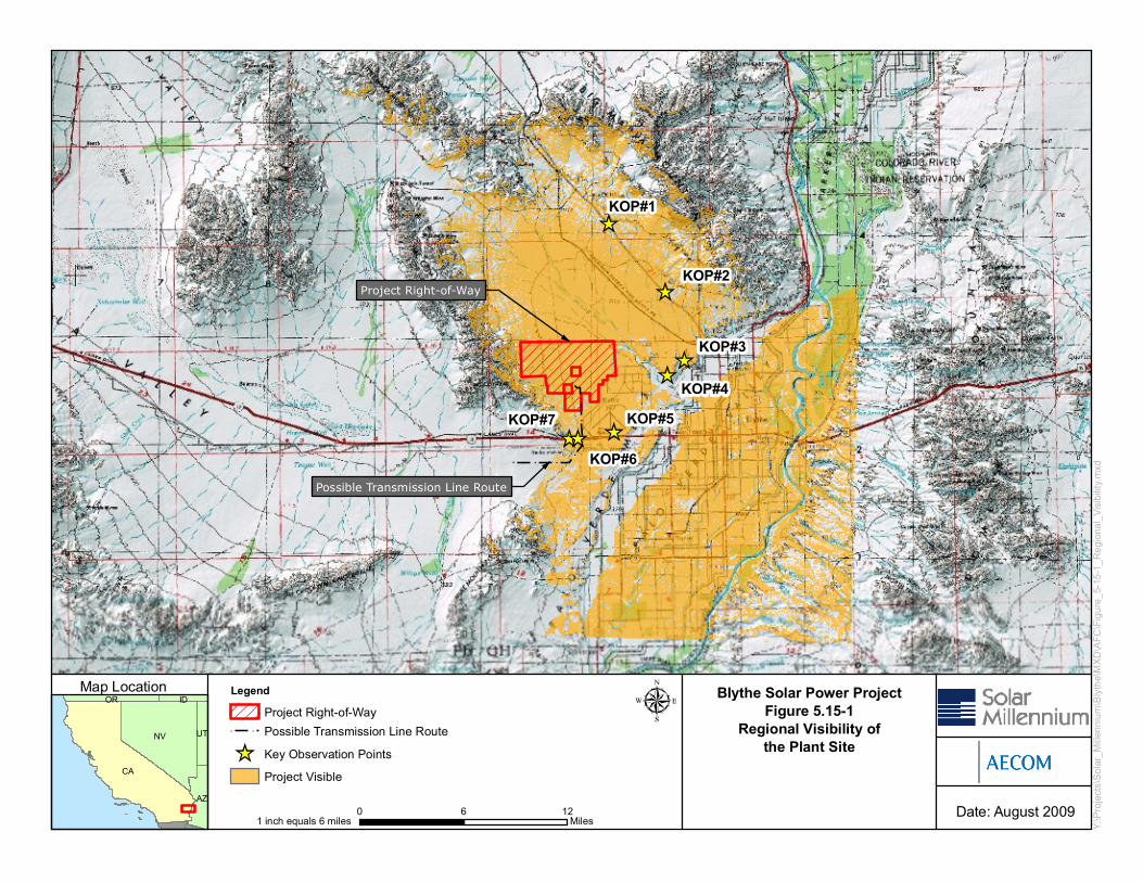
Blythe Solar Power ProjectFigure 5.15-1
Regional Visibility ofthe Plant Site
LEGEND
CA
NV
AZ
UT
OR IDMap Location
Date: August 2009
Y:\Pr
ojects
\Sola
r_Mille
nnium
\Blyt
he\M
XD\A
FC\Fi
gure_
5-15-1
_Reg
ional_
Visibi
lity.m
xd
Project Right-of-Way
Possible Transmission Line Route
KOP#3
KOP#7
KOP#6
KOP#2
KOP#1
KOP#4KOP#5
0 6 12Miles1 inch equals 6 miles
LegendProject Right-of-WayPossible Transmission Line RouteKey Observation PointsProject Visible

Blythe Solar Power ProjectFigure 5.15-2
Project Site andKey Observation Points
LEGEND
CA
NV
AZ
UT
OR IDMap Location
Date: August 2009
Y:\Pr
ojects
\Sola
r_Mille
nnium
\Blyt
he\M
XD\A
FC\Fi
gure_
5-15-2
_Key
_Obs
ervati
on_P
oints.
mxd
Project Right-of-Way
Possible Transmission Line Route
KOP#3
KOP#7
KOP#6
KOP#2
KOP#1
KOP#4
KOP#5
0 3 6Miles1 inch equals 3 miles
LegendProject Right-of-WayPossible Transmission Line RouteKey Observation Points

5.15 Visual Resources
Blythe Solar Power Project August 2009
Figure 5.15-3 - Characteristic Landscape of the Project Site

Blythe Solar Power ProjectFigure 5.15-4
Interm Visual Resource Management Classes
LEGEND
CA
NV
AZ
UT
OR IDMap Location
Date: August 2009
Y:\Pr
ojects
\Sola
r_Mille
nnium
\Blyt
he\M
XD\A
FC\Fi
gure_
5-15-4
_Inter
m_Vis
ual_R
esou
rce_M
anag
emen
t_Clas
ses.m
xd
Project Right-of-Way
Possible Transmission Line Route
Palen/McCoy
0 2 4Miles1 inch equals 2 miles
LegendProject Right-of-WayPossible Transmission Line RouteSensitivity Level: HighSensitivity Level: MediumWilderness AreaBLM Land
B-Scenic QualityC-Scenic QualityInterm VRM Class IIInterm VRM Class IIIInterm VRM Class IV

5.15 Visual Resources
Blythe Solar Power Project August 2009
Figure 5.15-5a - View from KOP-1 Looking Southwest Toward BSPP Site-Existing Condition

5.15 Visual Resources
Blythe Solar Power Project August 2009
Figure 5.15-5b - View from KOP-1 Looking Southwest Toward BSPP Site-Simulated Condition
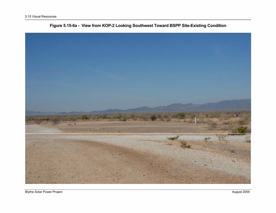
5.15 Visual Resources
Blythe Solar Power Project August 2009
Figure 5.15-6a - View from KOP-2 Looking Southwest Toward BSPP Site-Existing Condition

5.15 Visual Resources
Blythe Solar Power Project August 2009
Figure 5.15-6b - View from KOP-2 Looking Southwest Toward BSPP Site-Simulated Condition

5.15 Visual Resources
Blythe Solar Power Project August 2009
Figure 5.15-7a - View from KOP-3 Looking West Toward BSPP Site-Existing Condition

5.15 Visual Resources
Blythe Solar Power Project August 2009
Figure 5.15-7b - View from KOP-3 Looking West Toward BSPP Site-Simulated Condition

5.15 Visual Resources
Blythe Solar Power Project August 2009
Figure 5.15-8a - View from KOP-4 Looking West Toward BSPP Site-Existing Condition
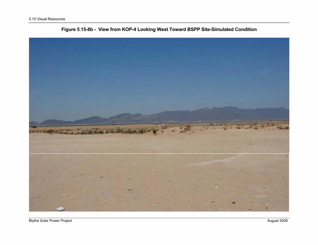
5.15 Visual Resources
Blythe Solar Power Project August 2009
Figure 5.15-8b - View from KOP-4 Looking West Toward BSPP Site-Simulated Condition

5.15 Visual Resources
Blythe Solar Power Project August 2009
Figure 5.15-9a - View from KOP-5 Looking North Toward BSPP Site-Existing Condition

5.15 Visual Resources
Blythe Solar Power Project August 2009
Figure 5.15-9b - View from KOP-5 Looking North Toward BSPP Site-Simulated Condition

5.15 Visual Resources
Blythe Solar Power Project August 2009
Figure 5.15-10a - View from KOP-6 Looking West Toward BSPP Transition Line-Existing Condition

5.15 Visual Resources
Blythe Solar Power Project August 2009
Figure 5.15-10b - View from KOP-6 Looking West Toward BSPP Transition Line-Simulated Condition

5.15 Visual Resources
Blythe Solar Power Project August 2009
Figure 5.15-11a - View from KOP-7 Looking East Toward BSPP Transition Line-Existing Condition

5.15 Visual Resources
Blythe Solar Power Project August 2009
Figure 5.15-11b - View from KOP-7 Looking East Toward BSPP Transition Line-Simulated Condition