594 diagnostic guide - perle
TRANSCRIPT

594 Diagnostic Guide
95-2457-04

Copyrig ht 1997-2000. Al l rights res erved, Perle System s Lim ited.
IBM and AS/400 are registered trademarks of International Business Machines Corporation.
All other trademarks appearing in this manual are trademarks of their respective companies.
FCC/DOC Compliance Statements:
NOTE: This equipment has been tested and found to comply with the limits for a Class A Digital Device, pursuantto Part 15 of the FCC rules and to DOC Radio Interference Regulations, C.R.C., c1374. These limits are designedto provide reasonable protection against harmful interference when the equipment is operated in a commercialenvironment. This equipment generates, uses, and can radiate radio frequency energy and, if not installed andused in accordance with the instruction manual, may cause harmful interference to radio communications.Operation of this equipment in a residential area is likely to cause harmful interference in which case the user willbe required to correct the interference at his own expense.
FCC/DOC compliance requires that all I/O cables used with Perle products be constructed using shielded cable,metal-shelled connectors and conductive backshells.
This equipment is approved in accordance with DIN IEC 380/VDE 0806/08.81. If this unit is installed as an officemachine, the installation must comply with the above standard.
Equipment must be used with an appropriately approved power supply cordset.
CAUTION: Changes or modifications to a Perle product which are not expressly approved by Perle SystemsLimited may void the users authority to operate the equipment.

Table of Contents
Chapter 1. Introduction. . . . . . . . . . . . . . . . . . . . . . . . . . . . . . . . . . . . . . . . . . . . . . 1Perle 594 Front View . . . . . . . . . . . . . . . . . . . . . . . . . . . . . . . . . . . . . . . . . . . . . . . . . . . . . . . . . . 1
Perle 594 Rear View . . . . . . . . . . . . . . . . . . . . . . . . . . . . . . . . . . . . . . . . . . . . . . . . . . . . . . . . . . . 1
Perle 594 Component Description. . . . . . . . . . . . . . . . . . . . . . . . . . . . . . . . . . . . . . . . . . . . . . . . . 2
Normal Power-On Sequence. . . . . . . . . . . . . . . . . . . . . . . . . . . . . . . . . . . . . . . . . . . . . . . . . . . . . 4
Power-On Options . . . . . . . . . . . . . . . . . . . . . . . . . . . . . . . . . . . . . . . . . . . . . . . . . . . . . . . . . . . . . 5
Operator Panel LEDs . . . . . . . . . . . . . . . . . . . . . . . . . . . . . . . . . . . . . . . . . . . . . . . . . . . . . . . . . . 6
LCD Message Formats . . . . . . . . . . . . . . . . . . . . . . . . . . . . . . . . . . . . . . . . . . . . . . . . . . . . . . . . . 7
Displaying the Date and Time . . . . . . . . . . . . . . . . . . . . . . . . . . . . . . . . . . . . . . . . . . . . . . . . . . . . 8
Setting the Date. . . . . . . . . . . . . . . . . . . . . . . . . . . . . . . . . . . . . . . . . . . . . . . . . . . . . . . . . . . . . . . 9
Setting the Time . . . . . . . . . . . . . . . . . . . . . . . . . . . . . . . . . . . . . . . . . . . . . . . . . . . . . . . . . . . . . . 9
Restarting Token-Ring Communication. . . . . . . . . . . . . . . . . . . . . . . . . . . . . . . . . . . . . . . . . . . . 10
Problem Determination . . . . . . . . . . . . . . . . . . . . . . . . . . . . . . . . . . . . . . . . . . . . . . . . . . . . . . . . 11
594 Utility Program References. . . . . . . . . . . . . . . . . . . . . . . . . . . . . . . . . . . . . . . . . . . . . . . . . . 15
Chapter 2. Concurrent Diagnostics . . . . . . . . . . . . . . . . . . . . . . . . . . . . . . . . . . . 17Controlling Access to Concurrent Diagnostics Information . . . . . . . . . . . . . . . . . . . . . . . . . . . . 17
Displaying Concurrent Diagnostics information using the 594 Utility . . . . . . . . . . . . . . . . . . . . . 18
Displaying Concurrent Diagnostics Information on an NWS (Perle 594e only) . . . . . . . . . . . . . . 20
Displaying Concurrent Diagnostics Data On the 594 Operator Panel. . . . . . . . . . . . . . . . . . . . . 55
Chapter 3. Extended Diagnostics . . . . . . . . . . . . . . . . . . . . . . . . . . . . . . . . . . . 113Running Extended Diagnostics . . . . . . . . . . . . . . . . . . . . . . . . . . . . . . . . . . . . . . . . . . . . . . . . . 114
The Extended Diagnostics Main Menu (020-01) . . . . . . . . . . . . . . . . . . . . . . . . . . . . . . . . . . . . 114
View Perle 594 Features . . . . . . . . . . . . . . . . . . . . . . . . . . . . . . . . . . . . . . . . . . . . . . . . . . . . . . 115
Test all Perle 594 hardware. . . . . . . . . . . . . . . . . . . . . . . . . . . . . . . . . . . . . . . . . . . . . . . . . . . . 115
Sync Card Loop-Back Diagnostic Test . . . . . . . . . . . . . . . . . . . . . . . . . . . . . . . . . . . . . . . . . . . 116
Token-Ring Loop-Back Diagnostic Test . . . . . . . . . . . . . . . . . . . . . . . . . . . . . . . . . . . . . . . . . . 117
Ethernet Loop-Back Diagnostic Test . . . . . . . . . . . . . . . . . . . . . . . . . . . . . . . . . . . . . . . . . . . . . 117
ASCII Loop-Back Diagnostic Test (Perle 594e only). . . . . . . . . . . . . . . . . . . . . . . . . . . . . . . . . 118
Set Date and Time. . . . . . . . . . . . . . . . . . . . . . . . . . . . . . . . . . . . . . . . . . . . . . . . . . . . . . . . . . . 118
Run Setup . . . . . . . . . . . . . . . . . . . . . . . . . . . . . . . . . . . . . . . . . . . . . . . . . . . . . . . . . . . . . . . . . 119
The Service Mode Main Menu (030-01) . . . . . . . . . . . . . . . . . . . . . . . . . . . . . . . . . . . . . . . . . . 119
Test Selected Perle 594 Hardware . . . . . . . . . . . . . . . . . . . . . . . . . . . . . . . . . . . . . . . . . . . . . . 120
Viewing the Perle 594 Time Stamped Error Log . . . . . . . . . . . . . . . . . . . . . . . . . . . . . . . . . . . . 121
System Reset . . . . . . . . . . . . . . . . . . . . . . . . . . . . . . . . . . . . . . . . . . . . . . . . . . . . . . . . . . . . . . 122
iii

Chapter 4. Use and Creation of Bridge Filter File . . . . . . . . . . . . . . . . . . . . . . . 123Criterion. . . . . . . . . . . . . . . . . . . . . . . . . . . . . . . . . . . . . . . . . . . . . . . . . . . . . . . . . . . . . . . . . . . 124
Criteria Lists . . . . . . . . . . . . . . . . . . . . . . . . . . . . . . . . . . . . . . . . . . . . . . . . . . . . . . . . . . . . . . . 127
Creating the Filter . . . . . . . . . . . . . . . . . . . . . . . . . . . . . . . . . . . . . . . . . . . . . . . . . . . . . . . . . . . 129
Sample Filters . . . . . . . . . . . . . . . . . . . . . . . . . . . . . . . . . . . . . . . . . . . . . . . . . . . . . . . . . . . . . . 131
Editing and Saving 594 Filter File . . . . . . . . . . . . . . . . . . . . . . . . . . . . . . . . . . . . . . . . . . . . . . . 133
Chapter 5. Network Computer Boot Server. . . . . . . . . . . . . . . . . . . . . . . . . . . . 135TFTP and FTP Log Files. . . . . . . . . . . . . . . . . . . . . . . . . . . . . . . . . . . . . . . . . . . . . . . . . . . . . . 135
Downloading Files From AS/400. . . . . . . . . . . . . . . . . . . . . . . . . . . . . . . . . . . . . . . . . . . . . . . . 136
Chapter 6. Message Codes . . . . . . . . . . . . . . . . . . . . . . . . . . . . . . . . . . . . . . . . . 137
Chapter 7. System Reference Codes . . . . . . . . . . . . . . . . . . . . . . . . . . . . . . . . . 147X.21 Switched Communication SRCs (200000-250300) . . . . . . . . . . . . . . . . . . . . . . . . . . . . . 165
SNA Communication SRC’s (400000-470200) . . . . . . . . . . . . . . . . . . . . . . . . . . . . . . . . . . . . . 170
Frame Relay Communication SRCs (560000-560410) . . . . . . . . . . . . . . . . . . . . . . . . . . . . . . 178
Frame Relay Token-Ring Bridge SRCs (570000-57FFFF) . . . . . . . . . . . . . . . . . . . . . . . . . . . 178
TCP/IP Error SRCs (5A000-5AFFFF) . . . . . . . . . . . . . . . . . . . . . . . . . . . . . . . . . . . . . . . . . . . . 181
Hardware Error SRCs (E00xxx) . . . . . . . . . . . . . . . . . . . . . . . . . . . . . . . . . . . . . . . . . . . . . . . . 184
Software Error SRCs (Fxxxxx) . . . . . . . . . . . . . . . . . . . . . . . . . . . . . . . . . . . . . . . . . . . . . . . . . 184
Appendix A. Memory . . . . . . . . . . . . . . . . . . . . . . . . . . . . . . . . . . . . . . . . . . . . . . 185Adding Memory Modules . . . . . . . . . . . . . . . . . . . . . . . . . . . . . . . . . . . . . . . . . . . . . . . . . . . . . 185
Removing Memory Modules . . . . . . . . . . . . . . . . . . . . . . . . . . . . . . . . . . . . . . . . . . . . . . . . . . . 187
Verifying System Memory Size . . . . . . . . . . . . . . . . . . . . . . . . . . . . . . . . . . . . . . . . . . . . . . . . . 188
Appendix B. Test Codes . . . . . . . . . . . . . . . . . . . . . . . . . . . . . . . . . . . . . . . . . . . 189
Index . . . . . . . . . . . . . . . . . . . . . . . . . . . . . . . . . . . . . . . . . . . . . . . . . . . . . . . . . . . 195
iv
Chapter 1. Introduction
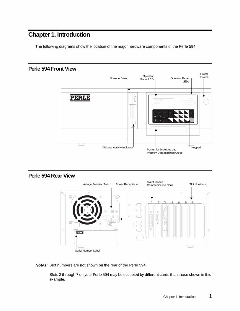
The following diagrams show the location of the major hardware components of the Perle 594.
Perle 594 Front View
Perle 594 Rear View
Notes: Slot numbers are not shown on the rear of the Perle 594.
Slots 2 through 7 on your Perle 594 may be occupied by different cards than those shown in this example.
ReadyCall Perle Service
See PD GuideTest Mode
Perle 594001-01
7ESC PF1 PF2
D
A
E
B
F
C
Req
Slot Clear
Ctrl Enter
PF3
Alt
0
8 9
4 5 6
1 2 3
4 9 45
Diskette DriveOperator
Panel LCD Operator PanelLEDs
Power Switch
KeypadPocket for Diskettes and Problem Determination Guide
Diskette Activity Indicator
11
5 V
1 2 3 4 5 6 7
Serial Number Label
Slot NumbersVoltage Selector Switch Power ReceptacleSynchronous Communication Card
Chapter 1. Introduction 1

Perle 594 Component Description
Operator Panel LCD
The Liquid Crystal Display (LCD) provides status messages for the Perle 594.
Operator Panel LEDs
There are four operator panel Light-Emitting Diodes (LEDs):
Power Switch
This switch is used to turn the power for the Perle 594 on and off. When the power is on, one or more of the operator panel LEDs will be on. When the power is off, none of the LEDs will be on. To turn the power on or off, press the power switch once.
Keypad
The 24-key keypad allows command entry to the Perle 594. The following is a description of how each key functions:
(Ready) When lit, this green LED indicates the Perle 594 is ready foroperation.
(Call Perle Service) When lit, this yellow LED indicates detection of an error conditionthat requires you to contact your 594 service representative.
(See PD Guide) When lit, this yellow LED indicates the Perle 594 has detected aproblem that requires diagnosis. Refer to Appendix C: SolvingProblems or the Perle 594 Problem Determination QuickReference for problem resolution instructions.
(Test Mode) This yellow LED is lit when the Perle 594 is in test mode,configuration mode, or when the Concurrent Diagnostics featureis enabled.
Key DescriptionEsc Cancel request.
PF1 Special request.
PF2 Special request.
PF3 Special request.
0—9 Numeric entry.
Pressing a number whi le holding the Alt keyproduces the following hexadecimal numbers:
2 Perle 594 Diagnostic Guide

Diskette Drive
The diskette drive is used to load software and configuration data from the Perle 594 Controller Software Diskette. Configuration can also be loaded from a 720Kb or 1.44Mb floppy diskette.
Diskette Activity Indicator
The diskette activity indicator comes on when the diskette drive is in use.
Warning: Do not remove the diskette from the diskette drive or power-off the Perle 594 when the diskette activity indicator is on.
Pocket for Diskettes and Problem Determination Quick Reference
This pocket provides a convenient location for storage of the Perle 594 Controller Software Diskette and the Perle 594 Problem Determination Quick Reference guide.
Voltage Selector Switch
The voltage selector switch is used to adjust the Perle 594 for the electrical service which is available at your site.
Alt + 4 Hexadecimal A
Alt + 5 Hexadecimal B
Alt + 6 Hexadecimal C
Alt + 7 Hexadecimal D
Alt + 8 Hexadecimal E
Alt + 9 Hexadecimal F
Req Initiates a status or function request.
↑ Scroll UP.
↓ Scroll DOWN.
Slot Enter slot selection mode.
Alt When held down, this key in combination withnumeric keys or PF keys produces alternate values.
Clear Clear the value currently being entered. Cancel thecurrent selection.
← Scroll LEFT.
→ Scroll RIGHT.
Ctrl Enter controller selection mode.
Enter End input string, or initiate selected function.
Chapter 1. Introduction 3

Power Receptacle
The power receptacle is used to connect the Perle 594 to a properly-grounded electrical outlet.
Synchronous Communication Card
The Synchronous Communication Card is always located in slot number 1.
Normal Power-On Sequence
During power-on, the Perle 594 diagnostics program performs system tests and loads the ControllerSoftware. The following information describes how the Perle 594 should function during power-on fornormal operation.
• All LEDs come on for one second and go off for one second, and then only the Test Mode LED comes on.
• The message code 001-01 is displayed on the LCD, indicating self tests are in progress.
• During self test a flashing asterisk is displayed on the right-hand side of the LCD.
• The Perle 594 system date and time are displayed.
• The message code 001-03 is displayed on the operator panel LCD while the Perle 594 controller Software is loaded
• The Test Mode LED goes off.
• On all attached, powered-on NWSs the System Available indicator is activated, the cursor moves to the upper left side of the screen, and each NWS is in free-key mode.
4 Perle 594 Diagnostic Guide

Power-On Options
When the Perle 594 is powered-on with the Perle 594 Controller Software diskette in the diskette drive,the Perle 594 will automatically enter operating mode. During power-on, the Perle 594 can also enterextended diagnostics and configuration mode. To be able to select the operating mode after poweringon, do the following:
Step 1 Ensure that the Perle 594 diskette drive is empty.
Step 2 Press the power switch. All LEDs will come on momentarily.
Step 3 The LCD displays the following message code, indicating that diagnostic tests are running:
001-01
Step 4 In a few moments, the following message code will appear:
003-02 1
Step 5 Locate the diskette that is appropriate for the power-on option that you want and ensure that the write-protect tab is closed (i.e., the diskette is not write-protected):
Step 6 On the keypad, type the appropriate digit.
Step 7 Press Enter.
To enter this mode: Insert:
Extended Diagnostics 594 Controller Setup Diskette
Configuration 594 Controller Setup Diskette
Normal 594 Controller Software Diskette
To enter this mode: Type:
Extended Diagnostics 0
Configuration 2
Normal 1
Chapter 1. Introduction 5

Operator Panel LEDs
The operator panel has the following LEDs:
Ready: This green LED comes on when the power-on diagnostics have been successfullycompleted, indicating the Perle 594 is ready for operation.
Call Perle Service: This LED comes on when an error condition is detected that requires you tocontact your 594 service representative. Write down all numbers displayed on the LCD and givethese numbers to the service representative.
See PD Guide: This LED comes on when the Perle 594 detects a problem that must be diagnosed.Write down all numbers displayed on the LCD and look up these numbers in:
• Chapters 6 and 7 of this guide
• Perle 594 Problem Determination Quick Reference
• "Appendix C: Solving Problems" in the User and Reference Guide.
Test Mode: This LED comes on when the Perle 594 is in test mode or configuration mode. When testsare running, the Ready LED is off. When the Perle 594 is in configuration mode or concurrentinformation is being displayed, the Ready LED is on.
LED Interpretation Table
To use this table, locate the bullet(s) ( • ) corresponding to the operator panel LEDs that are lit. Look atthe indication row for the note you should refer to for the appropriate explanation.
Note 1: A critical failure has occurred that prevents control of the operator panel LEDs, or an InitialProgram Load (IPL) successfully loaded the Perle 594 Controller Software, which is currentlyperforming initialization. If none of the LEDs are lit after two (2) minutes, refer to "Appendix C:Solving Problems" in the User and Reference Guide to determine the necessary action.
Note 2: The Power-On Self-Test (POST) or extended diagnostics are running.
Note 3: The Perle 594 has completed the POST and is in normal operation mode.
LEDs • means that the LED is lit.
Ready • • • •
Call Perle Service • •See PD Guide • •Test Mode • • • •
See Note: 1 2 3 4 5 6 7 8
6 Perle 594 Diagnostic Guide

Note 4: The Perle 594 is in configuration mode or information can be viewed concurrently.
Note 5: An error exists on the Perle 594 that requires service. Some function may be available. Contactyour 594 service representative.
Note 6: An error exists that requires further customer problem determination. Some function may beavailable. See Message Codes, on page and look up the message code displayed on the leftside of the operator panel LCD. The message code will suggest the appropriate action.
Note 7: An error has been detected by the POST or extended diagnostics. Service on the Perle 594 isrequired. See Message Codes, on page and look up the message code displayed on the left sideof the operator panel LCD. The message code will suggest the appropriate action.
Note 8: An error has been detected by POST or extended diagnostics. Further customer problemdetermination is required. See Message Codes, on page and look up the message codedisplayed on the left side of the operator panel LCD. The message code will suggest theappropriate action.
LCD Message Formats
The operator panel LCD has two lines for messages. The top line may be blank, or it may displaymessages in the following formats:
Top Line Format - 594e - compatible mode
The following format is used when the Perle 594e is operating in compatible mode:
Top Line Format - 594 - enhanced mode
In enhanced mode, either the top line is blank, or it displays additional information about an error condition. This information is displayed in one of the following two formats:
where the letters CCCCCCCC indicate the CP Name of the controller that is either reporting an error or the subject of Concurrent Diagnostics data. The actual data is displayed on the bottom line of the LCD.
or
where the letter X indicates a slot number of the card that is reporting an error and ## indicates the type of card that is reporting the error. The actual error code will be displayed on the bottom line of the LCD. The slot number X is always preceded by the number 0.
PERLE 594e
CCCCCCCC
0X ##
Chapter 1. Introduction 7

Bottom Line Format
The bottom line of the LCD has the following format:
The letters xxx-xx indicate either:
• a message code
or
• a Concurrent or Extended Diagnostics panel identifier.
Note: See Chapter 6 for a list of message codes.
The remaining data includes either:
• a System Reference Code (SRC) ranging from 3 to 6 digits in length, plus any additional information that is relevant to the message code or panel identifier.
or
• Concurrent or Extended Diagnostics data.
Note: See Chapter 7 for a list of SRCs and their meaning.
Displaying the Date and Time
To display the date and time do the following:
Step 1 Press Req and type 212. Press Enter . The following panel appears:
212-01|| yy-mm-dd
The current Perle 594 date appears in year-month-day format.
Step 2 Press the Up arrow key. The following panel appears:
212-02|| hh:mm:ss
The current Perle 594 time appears in hour-minute-second format.
Step 3 Press Esc to clear the panel.
Note: Error messages do not appear while a status request is being displayed.
xxx-xx aaaaaa(aaaa)
8 Perle 594 Diagnostic Guide

Setting the Date
To set the date while the Perle 594 is in operating mode, do the following:
Step 1 Press Req and type 213. Press Enter . The following panel appears:
213-01|| yy-mm-dd
Step 2 The date appears in year-month-day format. Enter the current date. Use the Right and Left arrow keys to move the cursor.
To quit without changing the date, press Esc.
Step 3 Press Enter .
If the new date is valid, the panel is cleared. If the date is not valid, a beep sounds.
Setting the Time
To set the time while the Perle 594 is in operating mode, do the following:
Step 1 Press Req and type 214. Press Enter . The following panel appears:
214-01|| hh:mm:ss
Step 2 Enter the current time. Use the Right and the Left arrow keys to move the cursor.
To quit without changing the time, press Esc.
Step 3 Press Enter . If the new time is valid, the panel is cleared. If the time is not valid, a beep sounds.
Date Valid Range
yy (year) 91 - 50 (1991 - 2050)
mm (month) 01 - 12
dd (day) 01 - 31
Time Valid Range
hh (hours) 00 - 23
mm (minutes) 00 - 59
ss (seconds) 00 - 59
Chapter 1. Introduction 9

Restarting Token-Ring Communication
Should the Perle 594 lose communication with the Token-Ring, this command can be used to restartcommunication. To restart Token-Ring communication, do the following:
Step 1 Press Req and type 230. Press Enter.
If a 594e is being used, and it is in compatible mode, then the Token-Ring has been restarted and the procedure is complete.
Step 2 If in enhanced mode, the following panel appears:
where X indicates the slot number of the Token-Ring Feature Card to be restarted.
Step 3 To change the slot number, use the Up or Down arrow key.
Step 4 Press Enter to restart the selected card.
0X 43
230 || 01
10 Perle 594 Diagnostic Guide

Problem Determination
To diagnose and resolve problems, do the following:
Step 1 Is a System Reference Code (SRC) displayed on any workstation?
Yes Look up the SRC in System Reference Codes, on page 147.
No Proceed to step 2.
Step 2 Is a 3-digit message code displayed on the operator panel LCD?
Yes Write down all numbers displayed on the LCD. Look up the message code in Message Codes, on page 137.
No Proceed to step 3.
Step 3 Is the Ready LED on?
Yes Go to step 11.
No Proceed to step 4.
Step 4 Do the following:
• Turn off the power on the Perle 594.
• Ensure that the Perle 594 Controller Software Diskette is inserted into the diskette drive.
• Turn on the power on the Perle 594.
Step 5 Does a message code appear within 2 minutes?
No Go to step 7.
Yes Proceed to step 6.
Step 6 Is the Ready LED on?
Yes The problem is resolved
No Call your 594 service representative.
Step 7 Check for one or more of the following signs that electrical power is reaching the Perle 594:
• The cooling fan is operating.
• One or more LEDs are on.
• A message appears on the LCD.
• The diskette activity indicator has come on.
Chapter 1. Introduction 11

Step 8 Is electrical power reaching the Perle 594?
Yes Call your 594 service representative.
No Go to step 9.
Step 9 Is the Perle 594 properly connected to the electrical outlet?
No Turn off the power on the Perle 594 and connect the power cord. The problem is resolved.
Yes Go to step 10.
Step 10 Test the outlet with another electrical device.
Is electrical power available?
No The problem has been located. Take the necessary steps to restore electrical power to the outlet.
Yes Call your 594 service representative.
Step 11 Are any twinaxial workstations not communicating?
Yes Proceed to step 12.
No Go to step 18.
Step 12 Locate the Twinaxial Feature Card to which the non-functioning workstation(s) are attached. Are any workstations communicating with this Twinaxial Feature Card?
No Go to step 16.
Yes Proceed to step 13.
Step 13 Are all non-communicating twinaxial workstations attached to the same port?
No Go to step 16
Yes Proceed to step 14.
Step 14 Do the following:
• Turn off the power on the Perle 594.
• Remove the cable from the failing port. Replace it with the cable from a functioning port.
• Ensure that the Perle 594 Controller Software Diskette is inserted into the diskette drive.
• Turn on power on the Perle 594.
12 Perle 594 Diagnostic Guide
Step 15 Do the workstations communicate with the port?
Yes The problem is with the twinaxial cable or the workstations attached to it. Take the necessary steps to correct the problem.
No Call your 594 service representative.
Step 16 Do the following:
• Ensure that the twinaxial workstation attachment cable is properly connected to the Twinaxial Feature Card
• Ensure that the twinaxial cables are properly connected to the twinaxial workstation attachment cable.
• Ensure that the twinaxial cables are properly connected to the workstations.
Step 17 Do these steps correct the problem?
Yes The problem is resolved.
No Call your 594 service representative.
Step 18 Are any Token-Ring workstations not communicating?
No Proceed to step 21.
Yes Proceed to step 19.
Step 19 Locate the Token-Ring Feature Card to which the non-functioning workstation(s) are attached. Are any workstations communicating with this Token-Ring Feature Card?
Yes The problem is with the Token-Ring network or the workstation attached to it. Take the necessary steps to correct the problem.
No Proceed to step 20.
Step 20 Ensure that the Token-Ring cable is properly connected to the Token-Ring Feature Card and to the MAU.
Is the Token-Ring cable properly connected?
No The problem is resolved.
Yes Call your 594 service representative.
Step 21 Are any Ethernet workstations not communicating?
Yes Proceed to step 22.
No Proceed to step 24.
Chapter 1. Introduction 13

Step 22 Locate the Ethernet Feature Card to which the non-functioning workstation(s) are attached. Are any workstations communicating with this Ethernet Feature Card?
Yes The problem is with the Ethernet network or the workstation attached to it. Take the necessary steps to correct the problem.
No Proceed to step 23.
Step 23 Ensure that the Ethernet cable is properly connected to the Ethernet Feature Card and to the concentrator hub or the network trunk. Is the Ethernet cable properly connected?
No The problem is resolved.
Yes Call your 594 service representative.
Step 24 Are any ASCII workstations not able to communicate?
Yes Proceed to step 25.
No If this procedure has been followed properly, the Ready LED is on and all workstations are communicating. Ensure that a problem exists and, if necessary, consult the operating procedures in this manual for further instructions.
Step 25 Is the display communicating with this port?
Yes Go to step 29.
No Proceed to step 26.
Step 26 Using a PC and modem with a configuration known to be correct, attempt a dial-up connection to the modem attached to this port. Is a connection established?
Yes The problem is with the remote PC, modem, or telephone lines. Go to step 28.
No Proceed to step 27.
Step 27 Verify the following cabling connections:
• The ASCII adapter cable to the ASCII Feature Card.
• The serial cable to the ASCII adapter cable.
• The serial cable to the modem.
• The modem to the telephone line.
If all cables are properly connected, attempt a dial-up connection to the modem. Is a connection established?
Yes The cabling problem has been resolved.
No Proceed to Step 28.
14 Perle 594 Diagnostic Guide

Step 28 Verify that the following configurations match:
• The local modem and the remote modem.
• The remote PC and the ASCII port.
Step 29 Verify the following:
• The printer is properly attached to the PC or terminal.
• The printer has adequate paper, toner, etc. and is able to print.
• The ASCII Port to which you are connecting supports a passthrough printer.
594 Utility Program References
Any reference to the 594 Utility Program throughout this manual applies to the 594e. For furtherinformation on using the 594 Utility program, refer to the appropriate User and Reference Guide.
Chapter 1. Introduction 15

16 Perle 594 Diagnostic Guide

Chapter 2. Concurrent Diagnostics
When determining or troubleshooting network problems, you can get detailed link configuration andstatus data while the 594 is on-line by using any of the following.
Controlling Access to Concurrent Diagnostics Information
Access to Concurrent Diagnostics information from all attached PWSs (remote or local) and NWSs (for594e only) is controlled from the 594 operator panel. This is called universal access.
When universal access is denied, individual 594 Utility access can be allowed by configuring a 594System Password and issuing it to authorized users only.
Granting Universal Access to Concurrent Diagnostics Information
To grant universal access to Concurrent Diagnostics information and suppress any 594 Utility passwordcontrol, do the following:
Step 1 Using the 594 operator panel keypad, press the Req key and type 290.
Step 2 Press Enter. The Test LED lights up, indicating that universal access to Concurrent Diagnostics information is granted.
Denying Universal Access to Concurrent Diagnostics Information
To deny universal access to Concurrent Diagnostics information and reinstate any existing 594 Utilitypassword control, do the following:
Step 1 Using the 594 operator panel keypad, press the Req key and type 291.
Step 2 Press Enter. The Test LED goes out, indicating that universal access to Concurrent Diagnostics information is denied.
Data request method Mode594 Utility on a PWS Compatible mode (594e only) or
Enhanced mode
NWS or PWS running 5250 emulation Compatible mode (594e only)
594 operator panel Compatible mode (594e only) or Enhanced mode
Chapter 2. Concurrent Diagnostics 17

Displaying Concurrent Diagnostics information using the 594 Utility
Use the 594 Utility from a PWS running AS/400 PC Support to request detailed link communicationinformation.
Note: For more information about the 594 Utility, refer to the User and Reference Guide.
Individual access to Concurrent Diagnostics information via the 594 Utility can be allowed. The systemoperator can suppress the password requirement by granting universal access to Concurrent Diagnosticsinformation. Refer to "Controlling Access to Concurrent Diagnostics Information" on page 17.
Remote Access and the 594 Utility Program
You can use the Utility Program from a PC that is attached locally to the 594 or from a PC that is attachedremotely to the 594 through an APPN network or IP. The Utility Program performs the same functions,including concurrent diagnostics, on a remotely attached PC as it does on a locally attached PC. For moreinformation about Remote Access, refer to the User and Reference Guide.
The Concurrent Diagnostic information that can be accessed through the 594 Utility program are asfollows:
• Network Information
• Error Log
• AS/400 Link Connection Information
• AS/400 Concurrent Host Attachment Information
• Twinaxial Status
• ASCII Status (Perle 594e only)
• LAN Gateway Adapter Status
• System Time-Stamped Log
• LAN Link Station Status (Gateway)
• LAN Link Station Status (Upstream)
• TCP/IP Status
• Default and Concurrent Host Tables per Port
• Source Route Bridging Status
• IP Routing Status
18 Perle 594 Diagnostic Guide

Starting a 594 Utility Concurrent Diagnostics Information Request
Before you can display Concurrent Diagnostics information by using the 594 Utility, either the systemoperator must grant universal access to Concurrent Diagnostics information, or you must know the 594System password.
To request Concurrent Diagnostics information from a PWS, do the following:
Step 1 Using the 594 Utility, choose Concurrent Diagnostics, Source Route Bridging Status or IP Routing Status from the main menu.
• If universal access has been granted, the Concurrent Diagnostics menu appears.
• If universal access has not been granted:
- If a 594 System Password has been configured, the system prompts you to enter the password.
- If no password has been configured, access is denied.
Step 2 If prompted, enter the 594 System Password.
Step 3 Choose the kind of information you need from the menu.
Note: When link connection status data changes after the request was made, 594Utility screens do not automatically display the new information. To update thedisplay, return to the Concurrent Diagnostics menu and reselect the option.
Step 4 If you used your password to access to Concurrent Diagnostics information, disable access by returning to the 594 Utility main menu.
Chapter 2. Concurrent Diagnostics 19

Displaying Concurrent Diagnostics Information on an NWS (Perle 594e only)
Use the NWS Concurrent Diagnostics Information Request procedure to display detailed,compatible-mode, link communication information from either an NWS or a PWS running 5250emulation.
While you are displaying Concurrent Diagnostics data at the workstation, customer applications continueto operate normally at all other workstations.
All NWS Concurrent Diagnostic screens display link configuration parameters. Individual screens alsodisplay the following data:
Starting an NWS Concurrent Diagnostics Information Request
Before you can display Concurrent Diagnostics information from either an NWS or a PWS running 5250emulation, universal access to Concurrent Diagnostics information must be granted. Refer to "GrantingUniversal Access to Concurrent Diagnostics Information" on page 17.
To display NWS Concurrent Diagnostics information:
Step 1 Vary off any current AS/400 communications session on the display you wish to use.
Step 2 Enter the Test Request key sequence that is appropriate to the keyboard you are using:
Step 3 Type C.
If universal access to Concurrent Diagnostics has been granted, diagnostic display screen C1 appears. The cursor appears at the screen number.
Step 4 To display the contents of screen C1, press Enter .
Screen Data Displayed
C1 Twinaxial interface error counts and error log buffer contents, which indicate those entries that have been sent to the current AS/400
C2 594 link status data, including:— Communication Error and Statistical Counter contents— Communication State Byte contents— SNA State Byte contents
C5 Twinaxial workstation configuration and status data
C6 594 system time-stamped error log
C8 LAN gateway adapter status data, including error counts
C9 Link Station status data.
CA 594 Concurrent host configuration and status
CB Frame Relay Token-Ring Bridge counters
Keyboard Test Request key sequence
83-key CMD Backspace
102/103-key ALT Test
122-key ALT Test
20 Perle 594 Diagnostic Guide
Step 5 To display the contents of a different screen, use the Up or Down arrow key to select the screen, and then press Enter to display its contents.
Note: Screens C3, C4, and C7 do not appear. Specific information about screens thatdo appear starts on page 33.
Step 6 To refresh the status information displayed on the screen, press Enter .
Resuming Normal Operations
To exit Concurrent Diagnostics and resume normal operations, restart the AS/400 session as follows:
Step 1 Press the Reset or Error Reset key two times.
Step 2 Power off the workstation.
Step 3 Wait 30 seconds, and then power on the workstation. If the 594 is on-line, an AS/400 signon screen appears within a few seconds.
Note: It may also be necessary to vary on the workstation device at the AS/400 system.
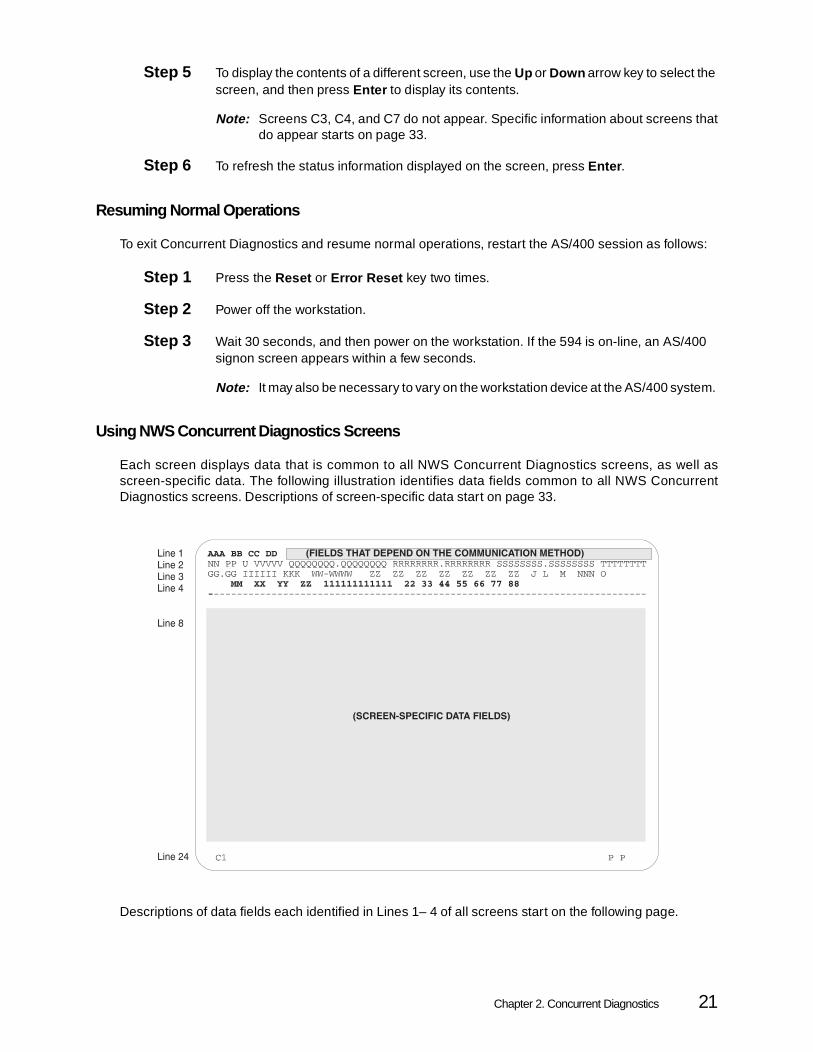
Using NWS Concurrent Diagnostics Screens
Each screen displays data that is common to all NWS Concurrent Diagnostics screens, as well asscreen-specific data. The following illustration identifies data fields common to all NWS ConcurrentDiagnostics screens. Descriptions of screen-specific data start on page 33.
Descriptions of data fields each identified in Lines 1– 4 of all screens start on the following page.
Chapter 2. Concurrent Diagnostics 21

All Screens: AS/400 Link Configuration Data (Line 1)
Most of the AS/400 link configuration data displayed at the top of each screen depends upon thecommunication method in use.
The following communications parameters have the same format, regardless of the communicationsmethod:
The remaining communications parameter fields differ in format as well as content for eachcommunication method.
AAA = Motherboard RAM storage size, in megabytes
BB = Number of twinaxial ports available
CC = communication method, where:00 = SDLC01 = X.2502 = X.21 Switched03 = X.21 Leased04 = Token-Ring05 = Ethernet06 = Frame Relay
DD = Current AS/400 system (01 through 04)
22 Perle 594 Diagnostic Guide

All Screens (line 1): SDLC or X.21 Leased
When you are using the SDLC/X.21 Leased communication method, the first line of the screenappears as follows:
For a description of fields AAA through DD, refer to "All Screens: Link Configuration Data (Line 1)" on page 22
EE = SDLC station address
F = Line type, where:0 = Leased1 = Switched
G = Line facility, where:0 = Half-duplex1 = Duplex
H = Connection type, where:0 = Multipoint1 = Point-to-point
I = Data encoding method, where:0 = NRZI (Non-Return to Zero Inverted)1 = NRZ (Non-Return to Zero)
J = Connection method, where:0 = DTR1 = CDSTL
K = Is Send Leading Pad byte required for synchronization?0 = No1 = Yes
NN = V.25 bis call connected timeout (01-FF).
LL = Line speed, where:00 = 1200 baud01 = 2400 baud02 = 3600 baud03 = 4800 baud04 = 7200 baud05 = 9600 baud06 = 14.4K baud07 = 19.2K baud08 = 38.4K baud09 = 48K baud10 = 56K baud11 = 64K baud12 = 128K baud
Chapter 2. Concurrent Diagnostics 23

All Screens (line 1): X.25
When you are using the X.25 communication method, the first line of the screen appears asfollows:
For a description of fields AAA through DD, refer to "All Screens: Link Configuration Data (Line 1)" on page 22.
EE = LLC station address
FFF = Default logical channel identifier
G = Sequence numbering0 = Modulo 81 = Modulo 128
H = Packet window size (2– 7)
I = Link window size (1– 7)
J = Packet size, in bytes, where:0 = 641 = 1282 = 2563 = 5124 = 1024
K = Virtual circuit type, where:0 = SVC1 = PVC2 = SVCIN3 = PVCAUTO
L = Flow Control, where0 = Not Permitted1 = Permitted
M = Manual Options, where0 = Not permitted1 = Permitted
O = Reverse Charging, where0 = Not accepted1 = Accepted
P = LLC selection, where:0 = QLLC1 = ELLC
Q = Status of U.K. Switch Stream or Telenet-type network link, where:0 = Not attached1 = Attached
24 Perle 594 Diagnostic Guide

All Screens (Line 1): X.21 Switched
When you are using X.21 Switched, the first line of the screen appears as follows:
For a description of fields AAA through DD, refer to "All Screens: Link Configuration Data (Line 1)" on page 22.
R = Link initiation, where:0 = Link initiated by either 594 or network1 = Link initiated by network
S = Subscription, where0 = 19881 = 19842 = 1980
T = Diagnostic Codes, where0 = 1984/1988 SNA1 = 1984/1988 ISO2 = 1980 SNA
XX = Retry counter setting, in hexadecimal (00– FF)
YY = Retry interval setting, in hexadecimal (00– 1C)
EE = SDLC station address
FFF = Access code
G = Dial digit format, where:0 = DNIC1 = DCC
HH = SHM (Short Hold Mode) Recall counter (00– FF, in hexadecimal)
I = SHM (Short Hold Mode) Recall Delay time (0– F, in hexadecimal)
J = Call support type, where:0 = SHM (Short Hold Mode) recall address1 = SHM (Short Hold Mode) recall direct
KK– RR = Call Progress Signals (CPSs)
Note: A value of `A' in this group of fields indicates that there is no entry.
Note: These CPSs will be retried during SHM link reestablishment.
Chapter 2. Concurrent Diagnostics 25

All Screens (Line 1): Token-Ring
When you are using Token-Ring, the first line of the screen appears as follows:
For a description of fields AAA through DD, refer to "All Screens: Link Configuration Data (Line 1)" on page 22.
EEEEEEEEEEEE = AS/400 system Token-Ring address
FF = AS/400 system SAP (Service Access Point)
GGGGGGGGGGGG= 594 Token-Ring address
HH = 594 system SAP (Service Access Point)
II = Token-Ring Response time (T1): Amount of time allowed for the 594 to wait for an acknowledgment or response from the LAN (01– 14 seconds, in hexadecimal)
Note: A value of ̀ *' indicates that the 594 uses routing information to calculate the value for T1.
JJ = Token-Ring Inactivity time (Ti): Amount of time allowed for the 594 to detect a LAN error condition (01– 63 seconds, in hexadecimal)
KK = Token-Ring Receive Acknowledgment time (T2): Amount of time allowed for the 594 to send acknowledgments to the LAN (01– FF seconds, in hexadecimal)
LL = Token-Ring retry count (N2): Maximum number of retries allowed for the 594 to establish an AS/400-to-LAN workstation connection, following T1 timer expiration (00– FF times, in hexadecimal)
MM = Token-Ring Maximum Out (TW): Maximum number of I-frames that the 594 can send before receiving acknowledgment (02– 08 frames)
NN = Token-Ring Maximum In (N3): Maximum number of I-frames that the 594 can receive before sending acknowledgment (01– 04 frames)
OO = Adapter rate, where:04 = 4 Mbps16 = 16 Mbps
26 Perle 594 Diagnostic Guide
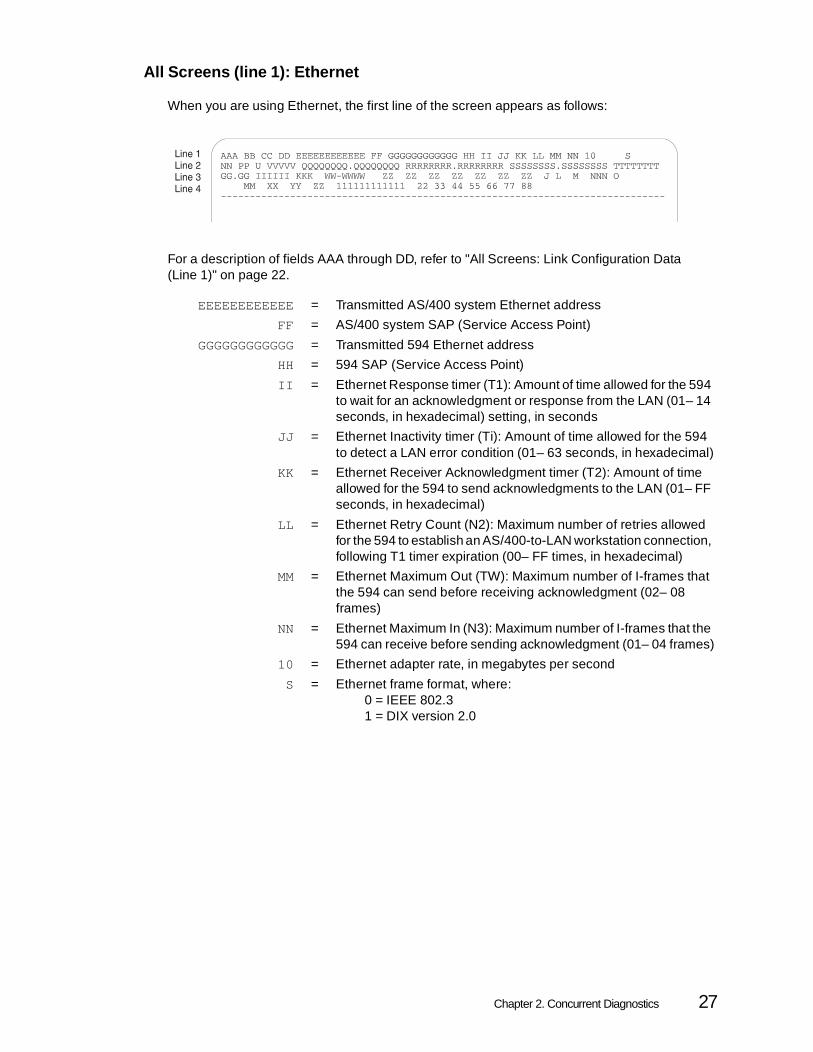
All Screens (line 1): Ethernet
When you are using Ethernet, the first line of the screen appears as follows:
For a description of fields AAA through DD, refer to "All Screens: Link Configuration Data (Line 1)" on page 22.
EEEEEEEEEEEE = Transmitted AS/400 system Ethernet address
FF = AS/400 system SAP (Service Access Point)
GGGGGGGGGGGG= Transmitted 594 Ethernet address
HH = 594 SAP (Service Access Point)
II = Ethernet Response timer (T1): Amount of time allowed for the 594 to wait for an acknowledgment or response from the LAN (01– 14 seconds, in hexadecimal) setting, in seconds
JJ = Ethernet Inactivity timer (Ti): Amount of time allowed for the 594 to detect a LAN error condition (01– 63 seconds, in hexadecimal)
KK = Ethernet Receiver Acknowledgment timer (T2): Amount of time allowed for the 594 to send acknowledgments to the LAN (01– FF seconds, in hexadecimal)
LL = Ethernet Retry Count (N2): Maximum number of retries allowed for the 594 to establish an AS/400-to-LAN workstation connection, following T1 timer expiration (00– FF times, in hexadecimal)
MM = Ethernet Maximum Out (TW): Maximum number of I-frames that the 594 can send before receiving acknowledgment (02– 08 frames)
NN = Ethernet Maximum In (N3): Maximum number of I-frames that the 594 can receive before sending acknowledgment (01– 04 frames)
10 = Ethernet adapter rate, in megabytes per second
S = Ethernet frame format, where:0 = IEEE 802.31 = DIX version 2.0
Chapter 2. Concurrent Diagnostics 27

All Screens (line 1): Frame Relay
When you are using Frame Relay, the first line of the screen appears as follows:
For a description of fields AAA through DD, refer to "All Screens: Link Configuration Data (Line 1)" on page 22.
EEE = Data Link Connection Identifier (DLCI)
F = 0 = Leased
G = 1 = Duplex
H = 1 = Point-to-Point
I = Zero Insertion, where:0 = NRZI1 = NRZ
J = 0 = DTR
K = 0 = Do not send pad
L = 0 = No local loopback
MM = AS/400 SAP
NN = 594 SAP
O = LMI Mode, where:0 = No LMI1 = ANSI, Annex D2 = CCITT
PP = Polling interval in seconds (POLLITV)
QQ = Full inquiry interval in cycles (FULLINQITV)
RR = Response timer (T1) in seconds
SS = Inactivity timer (Ti) in seconds
TT = Receiver acknowledgment timer (T2) in milliseconds
UU = Retry counter (N2)
VV = Maximum frames out (TW)
WW = Maximum frames in (N3)
28 Perle 594 Diagnostic Guide

All Screens: Network Configuration Data (Line 2)
Line 2 contains the same kind of data for all communication methods.
Data fields display the following network configuration information.
NN = Logical Connection Retry counter
PP = Logical Connection Retry interval
U = Continuous retry field, where:
0 = Once the retry count expires, there are no more retries
1 = Once the retry count expires, retries occur continuously at 10-minute intervals
VVVVV = 594 ID configured by the user or * if there is no ID configured
QQQQQQQQ.QQQQQQQQ= 594 network-qualified logical unit (LU) name
RRRRRRRR.RRRRRRRR = 594 network-qualified control point (CP) name
SSSSSSSS.SSSSSSSS = AS/400 network-qualified logical unit (LU) name
TTTTTTTT = Mode name
Chapter 2. Concurrent Diagnostics 29

All Screens: 594 Specifications (line 3)
Line 3 contains the same kind of data for twinaxial and LAN communication methods.
Data fields contain the following 594 hardware and code specifications:
GG.GG = 594 release number
IIIIII = 594 release date
KKK = Communication cable type ID, where:000 = X.21 DTE001 = V.35 DTE010 = EIA 232D DTE011 = no cable attached100 = X.21 DCE101 = X.35 DCE110 = EIA 232D DCE111 = Loopback header attached
WW-WWWWW= Serial number
ZZ = Card ID for the 594 slots 1-7, where:00 = empty slot96 = Synchronous Communication Card (594e)41 = Twinaxial Feature Card42 = ASCII Feature Card (594e)43 = Token-Ring Feature Card44 = DBCS Twinaxial Feature Card45 = Ethernet Feature Card48 = Twinaxial Feature Card49 = Fast Ethernet Feature Card
J = Indicates when the controller session with the AS/400 will be initiated, where:0 = When the first NWS or PWS powers on1 = Immediately.
L = Indicates controller session termination with the AS/400, where:
0 = Terminate the controller session when the AS/400 indicates that there are no active NWS or PWS sessions.
1 = Do not terminate the controller session when the AS/400 indicates that there are no active sessions.
M = Indicates if the concurrent host is configured, where:0 = NO1 = YES
NNN = If concurrent host is configured, this is the printer timeout value showing the number of seconds a 594 controller waits before accepting a print job from a different host. If zero, printer sharing is disabled.
O = Indicates if AS/400 date and time synchronization is configured, where:
0 = Do not set the 594 date and time to the primary AS/400 date and time.1 = Set the 594 date and time to the primary AS/400 date and time.
30 Perle 594 Diagnostic Guide

Note: The first ZZ field, representing Slot 1, always has a value of '40' for the 594e, '72' for the 594A, or '64' for the 594T.
All Screens: LAN Gateway and LAN and Twinaxial Device Configuration Data (Line 4)
Line 4 contains the same kind of data for all communication methods.
Fields contain configuration data for connected LAN and twinaxial devices.
Note: Fields MM and XX are displayed whether or not a LAN gateway is configured. Remaining fields appear only when a LAN gateway is configured.
MM = Maximum number of LAN workstations supported by the current configuration
XX = LAN gateway adapter configuration, where:00 = not configured01 = Token-Ring02 = IEEE 802.3 Ethernet03 = DIX Version 2.0 Ethernet
YY = LAN gateway adapter status, where:00 = closed01 = open
ZZ = LAN speed, where:04 = 4 Mbps (Token-Ring)10 = 10 Mbps (Ethernet)16 = 16 Mbps (Token-Ring)
111111111111 = Transmitted 594 LAN gateway address
22 = 594 LAN gateway service access point (SAP)
33 = LAN gateway Response timer (T1): Amount of time allowed for the 594 to wait for an acknowledgment or response from the LAN (01– 14 seconds, in hexadecimal)
44 = LAN gateway Inactivity timer (Ti): Amount of time allowed for the 594 to wait for an acknowledgment or response from the LAN (01– 14 seconds, in hexadecimal)
55 = LAN gateway Receive Acknowledgment timer (T2): Amount of time allowed for the 594 to send acknowledgments to the LAN (01– FF seconds, in hexadecimal)
66 = LAN gateway Retry Count (N2): Maximum number of retries allowed for the 594 to establish an AS/400-to-LAN workstation connection, following T1 timer expiration (00– FF times, in hexadecimal)
77 = LAN gateway Maximum Out (TW): Maximum number of I-frames that the 594 can send before receiving acknowledgment (02– 08 frames)
88 = LAN gateway Maximum In (N3): Maximum number of I-frames that the 594 can receive before sending acknowledgment (01– 04 frames)
Chapter 2. Concurrent Diagnostics 31

All Screens: Screen Selection Field (line 24)
The first field of Line 24 (the Cx field in the lower left corner of the screen) identifies the current NWSscreen. The first character C identifies the screen as a Concurrent Diagnostics screen. The secondcharacter identifies which screen is displayed in the Concurrent Diagnostics screen series.
This field is referred to as the Screen Selection Field because you can use it to move from one screento another. If you have just started an NWS Concurrent Diagnostics session, this field displays thevalue "C1" and the cursor is in the second position of the field. To select a different screen, use theUp or Down arrow key until the field displays the screen you want. To display the contents of theselected screen, press Enter .
All Screens: Printer Selection Field (Line 24)
The last field of Line 24 (the P P field in the lower right corner of the screen) identifies the port andstation address of the printer selected for Concurrent Diagnostic screen printing (the copy-to-printerutility).
If no default value has been configured, the field displays a value of `– – '.
To select a different printer, use the Up or Down arrow key. You can do so whether or not a defaultprinter has been configured.
To send the contents of the current screen to the selected printer, press the Print key. If no printeraddress is specified, the 594 polls attached workstations and sends the job to the first availableprinter.
Line 1Line 2Line 3Line 4
Line 8
Line 24
----------------------------------------------------------------------------
(SCREEN-SPECIFIC DATA FIELDS)
C1 P P
(COMMON DATA FIELDS)
32 Perle 594 Diagnostic Guide

C1 Screen: 594 Error Log Buffer Contents
The C1 screen displays contents of the 594 error log buffer—at the time of the request—in athree-column section in the middle of the screen. To update the display at any time, press Enter .
Those entries sent to the AS/400 system appear above the second dashed line on the screen; allothers appear below that dashed line. Within each group, the first entry of the first column is the oldestentry. Entries are sent to the AS/400 system whenever either of the following occurs:
• the 594 is varied on or off
• error counters overflow.
Note: Except for indication of which error log entries have been (and have not been) sent to the current AS/400, the same error log is displayed in a more complete format on the C6 screen.
In the error log buffer display, each 594 error log entry has the following format:
LL FFFF FFSSSSSSSS or:
LL EEEE SSSSSSSSSS where:
LL = Logical session ID indicating the session in which the error was detected.
Note: A value of `00' identifies the 594 rather than the logical session ID for some SRCs.
EEEEor
FFFF FF = SRC
Note: The first digit of a 2-byte SRC is 0.
SSSSSSSS(SS) = Sense data (may be blank)
Line 1Line 2Line 3Line 4
Line 24
----------------------------------------------------------------------------
LL EEEE SSSSSSSSS LL EEEE SSSSSSSSS LL EEEE SSSSSSSSS
LL EEEE SSSSSSSSS
----------------------------------------------------------------------------
LL EEEE SSSSSSSSS LL EEEE SSSSSSSSS LL EEEE SSSSSSSSS
LL EEEE SSSSSSSSS LL EEEE SSSSSSSSS LL EEEE SSSSSSSSS
LL EEEE SSSSSSSSS LL EEEE SSSSSSSSS LL EEEE SSSSSSSSS
LL EEEE SSSSSSSSS LL EEEE SSSSSSSSS LL EEEE SSSSSSSSS
LL EEEE SSSSSSSSS LL EEEE SSSSSSSSS LL EEEE SSSSSSSSS
LL EEEE SSSSSSSSS LL EEEE SSSSSSSSS LL EEEE SSSSSSSSS
LL FFFF FFSSSSSS
C1 P P
(COMMON DATA FIELDS)
(TWINAXIAL INTERFACE COUNTERS)
Chapter 2. Concurrent Diagnostics 33

C1 Screen: Twinaxial Interface Error Counts
The C1 screen displays two kinds of twinaxial workstation error counts in the lowest section of thedata display.
Transmit activity check (TAC) error counts appear in the left half of the section and parity-timeout errorcounts appear in the right half of the section, where:
AAAA = TAC error counts for each port (0– 7)
BBBB = Parity-timeout error counts for each port (0– 7).
Line 1Line 2Line 3Line 4
Line 24
----------------------------------------------------------------------------
(ERROR LOG BUFFER CONTENTS)
C1 P P
(COMMON DATA FIELDS)
AAAA AAAA AAAA AAAA BBBB BBBB BBBB BBBBAAAA AAAA AAAA AAAA BBBB BBBB BBBB BBBB
34 Perle 594 Diagnostic Guide

C2 Screen: AS/400 Link Status Data
The C2 screen displays bytes and registers that indicate the status of the link between the 594 andthe current AS/400 system at the time of the request. To update the display at any time, press Enter .
Fields include:
• Communications Error And Statistical CountersThe statistical counts (BBBBBBBB fields) displayed on the C2 screen show the numbers ofI-frames transmitted and received by the 594 during the current AS/400 session. The types ofcommunications error counts depend on both the communications protocol and the cable usedfor the connection. For a description of error counters (the AA fields) as they appears for eachunique combination of protocol and cable type, see "SDLC, X.21, and X.25 CommunicationsCounter Code Descriptions (60– 6D)", starting on page 79.
• Communication State ByteContains a record of any attempt, at the time of the request, to establish a logical connection withthe AS/400 system.
• SNA State ByteContains a record of any attempt by the 594 to establish a logical connection with the Logical Unit(LU) of the AS/400 system.
• Communication Interface Register Contains data about the 594-AS/400 connection rather than the communication method.Interpretation of the contents depends on the cable type used for the 594-AS/400 connection.
• Host attachment status and configuration informationContains configuration and status information for the four possible hosts that can be configuredon the 594.
The contents of each field depend upon the communication method. The following subsectionsdescribe each byte and register that appears for each communication method.
Chapter 2. Concurrent Diagnostics 35

C2 Screen: AS/400 Interface Status Data
When the 594 communicates with the current AS/400 system over a physical interface, the C2screen displays data in the following format:
The C2 screen displays the following fields:
Communications error and statistical counterswhere:
AA = Communications error counts
BBBB = Communications statistics counts
Connections numberswhere:
CCCCCCCCCCCCCC= 594 connection number
DDD...DDD = AS/400 system connection number
A = Communications state bytesfor SDLC or X.21 Leased
a = Was the received address verified against the configured address?0 = No1 = Yes
b = FSC: Had the 594 received at least one good frame?0 = No1 = Yes
c = XID: Had the 594 received the XID frame?0 = No1 = Yes
d = SNRM: Had the 594 been ready to respond to the AS/400?0 = Set Normal Response Mode (SNRM) was not entered1 = SNRM was entered
e = Had the 594 ever entered Normal Response Mode (NRM)?0 = No1 = Yes
36 Perle 594 Diagnostic Guide

f = (Reserved)
g = (Reserved)
h = What is the current state of the 594?0 = Normal Disconnect Mode (NDM)1 = Normal Response Mode (NRM)
Note : The SDLC/X.21 Leased communication state byte is reset when-ever a correct address is received while the 594 is in disconnect mode.
for X.25
a = Was the received address verified against the configured address?0 = No1 = Yes
b = FSC: Had the 594 received at least one good frame?0 = No1 = Yes
c = UA: Had the unnumbered acknowledgment been received from thepreviously sent SABM signal?
0 = No1 = Yes
d = Had the 594 confirmed that the Packet Level had restartedfollowing a Request To Send (RTS)?
0 = No1 = Yes
e = (Reserved)
f = (Reserved)
g = (Reserved)
h = (Reserved)
Note: The X.25 communication state byte is reset whenever a correct address is received while the 594 is in disconnect mode.
for X.21 Switched
a = Had the 594 started a call sequence?0 = No1 = Yes
b = Had the 594 entered State 12, SDLC mode?0 = No1 = Yes
c = Was the received address verified against the configured address?0 = No1 = Yes
d = FSC: Had the 594 received at least one good frame?0 = No1 = Yes
e = XID: Had the 594 received the XID frame from the AS/400?0 = No1 = Yes
f = SNRM: Had the 594 been ready to respond to the AS/400?0 = Set Normal Response Mode (SNRM) was not entered1 = SNRM was entered
Chapter 2. Concurrent Diagnostics 37

g = Had the 594 ever entered Normal Response Mode (NRM)?0 = No1 = Yes
h = What is the current state of the 594?0 = Normal Disconnect Mode (NDM)1 = Normal Response Mode (NRM)
Note : Bits b through g of the X.21 Switched communication state byte are reset whenever an incoming or outgoing call is initiated.
B = SNA state byte, where:
a = 1 if the Activate Logical Unit (ACTLU) signal was received
b = (Reserved)
c = 1 if the SNA LU 4 or 7 BIND was complete
d = 1 if accepting workstation data streams
e = 1 if an engineering change (EC) load was in progress
f = 1 if an engineering change (EC) load was flagged
g = 1 if LU 6.2 controller session is active
h = 1 if Primary host download was complete
C = Communication Interface Register
0 indicates that the signal is active; 1 indicates that the signal is inactive.
When the cable type is EIA 232D (V.24/28) or V.35:
a = Receive Data (RD)
b = (Reserved)
c = Receive clock (RSET)
d = Transmit clock (TSET)
e = Data Set Ready(DSR)
f = Ready For Sending (RFS)
g = Carrier Detect (CD)
h = Calling Indicator (CI)
i = Transmit Data (TD)
j = Data Terminal Ready (DTR) or Connect Data Set to Line (CDSTL)
k = Request To Send (RTS)
l = Local Loopback
m = (Reserved)
n = (Reserved)
o = (Reserved)
p = (Reserved)
When the cable type is X.21:
a = Receive Data (RD)
b = (Reserved)
c = Network clock
d = Network clock
e = (Reserved)
f = (Reserved)
38 Perle 594 Diagnostic Guide

g = Indicate (I
h = 1 if Transmit Wait For Network Ready
i = Transmit Data (TD)
j = (Reserved)
k = Control (C)
l = (Reserved)
m = 1 if DCE Not Ready
n = (Reserved)
o = 1 if Wait for Proceed to Select
p = (Reserved)
D = Concurrent host attachment, where:
H1, H2,H3, H4
= If the concurrent host feature is enabled, these numbers are displayed and represent the number of the configurable host. However, information is not displayed in the fields following the host numbers for those hosts that are not yet configured.
P = Indicates the status of the host, where:0 = Alternate host1 = Primary host2 = Alternate host that is currently receiving alert
messages while the primary host is inactive.
X = Indicates the status of the link. This field is set to 1 for only one host.
0 = This host is not the first ALS that the 594 controller contacted. If this field is set to 0 for the rest of the hosts, there is no active link.
1 = The first ALS has been activated. It is now possible to link to the other hosts through this ALS.
A = Indicates whether this AS/400 has been contacted, where:0 = AS/400 has not been contacted.1 = AS/400 has been contacted.
S = Indicates whether the controller session is active with this host, where:
0 = Controller session is not active with this host.1 = Controller session is active with this host.
J = Indicates when the controller session for this host will be initiated, where:
0 = When the first NWS (or PWS if this host is the primary host) is powered on.
1 = Immediately. The controller session will not wait for an active NWS.
Chapter 2. Concurrent Diagnostics 39

L = Indicates when the controller session for this host will be terminated, where:
0 = When the AS/400 indicates that there are no active NWS sessions.
1 = The controller session will not be terminated when the AS/400 indicates that there are no active sessions.
Note : The controller session to the host receiving 594 controller alert messages is terminated only when there are no active NWS or PWS sessions with any host.
UUUUUUUU = Identifies the LU name for this host.
VVVVVVVV = Identifies the network name for this host.
WWWWWWWW= Identifies the 594 network name for this host.
XXXXXXXX = Identifies the node name for this host.
40 Perle 594 Diagnostic Guide

For a Token-Ring connection
Communications error and statistical counters, where:
EEEEEEEE = Line error count
FFFFFFFF = Burst error count
GGGGGGGG= Abort Delimiter count
HHHHHHHH= Receive Congestion error count
IIIIIIII = Frequency error count
JJJJJJJJ = Internal error count
KKKKKKKK = Access Control (a/c) error count
LLLLLLLL = Lost frame count
MMMMMMMM= Frame Copy error count
NNNNNNNN= Token error count
QQ = Numeric overflow from the preceding field
PPPP = Data about routing to the current AS/400 system
A = Communication State Byte, where:
a = (Reserved)
b = (Reserved)
c = (Reserved)
d = (Reserved)
e = (Reserved)
f = (Reserved)
g = Is the Token Ring adapter open?0 = No1 = Yes
h = Token Ring speed, where:0 = 4 Mbps1 = 16 Mbps
B = SNA State Byte - See description on page 38.
D = Concurrent Host Attachment - See description on page 39.
Chapter 2. Concurrent Diagnostics 41

For an Ethernet connection
Communications error and statistical counters, where:
EEEEEEEE = Transmit error count.
FFFFFFFF = Receive congestion count.
QQ = Numeric overflow from the preceding field.
A = Communication State Byte, where:
a = (Reserved)
b = (Reserved)
c = (Reserved)
d = (Reserved)
e = (Reserved)
f = (Reserved)
g = Is the Ethernet adapter open?0 = No1 = Yes
h = (Reserved)
B = SNA State Byte - See description on page 38.
D = Concurrent Host Attachment - See description on page 39.
42 Perle 594 Diagnostic Guide

For a Frame Relay connection
Communications error and statistical counters, where:
EEEEEEEE = LMI timeout count
FFFFFFFF = LMI sequence error count
GGGGGGGG= LMI protocol error count
HHHHHHHH= PM DSR error count
IIIIIIII = PM CTS error count
JJJJJJJJ = Aborted frames
KKKKKKKK = FCS errors
LLLLLLLL = Residue errors
MMMMMMMM= Overruns
NNNNNNNN= Underruns
OOOOOOOO= No receive buffers count
PPPPPPPP = Misaddresses frames
A = Communication State Byte, where:
a = (Reserved)
b = (Reserved)
c = (Reserved)
d = (Reserved)
e = (Reserved)
f = (Reserved)
g = Is the Frame Relay adapter open?0 = No1 = Yes
h = (Reserved)
B = SNA State Byte - See description on page 38.
C = Communication Interface Register - See description on page 38.
D = Concurrent Host Attachment - See description on page 39.
Chapter 2. Concurrent Diagnostics 43

C5 Screen: Twinaxial Workstation Configuration and Status Data
The C5 screen displays configuration and status data for each workstation address on the selectedtwinaxial port. When a workstation is not responding to polls, the status fields (in the middle sectionof the screen) are blank for that address. To update the display at any time, press Enter .
The Port Selection field P is located on line 24, to the right of the Screen Selection field. To select adifferent port, place the cursor at the Port Selection field and use the Up or Down arrow key. To displayworkstation configuration and status data for the port, press Enter .
For each twinaxial workstation, the C5 screen displays two rows of data:
Row 1 contains the following data fields:
PS = Workstation Address, where:P = Port (0– 7)S = Station (0– 6)
1000 0000 0000 0000 = Indication that a workstation is responding to polls
AAAA = Device type code
BBB = Device model code
K = OptionalCharacteristics of newer workstations, where:
a = 1, color monitorb = 1, wide screen monitorc = 1, separate error line d = 1, text symbols availablee = 1, shadow cursor f = reservedg = 1, extended character bufferh = 1, double-byte characters
Line 1Line 2Line 3Line 4
Line 24
----------------------------------------------------------------------------PS 1000 0000 0000 0000 AAAA BBB abcd efgh CC
DD EE FF abcd efgh GGGGGG HH
PS 1000 0000 0000 0000 AAAA BBB abcd efgh CCDD EE FF abcd efgh GGGGGG HH
PS CC
PS CC
PS 1000 0000 0000 0000 AAAA BBB abcd efgh CCDD EE FF abcd efgh GGGGGG HH
PS 1000 0000 0000 0000 AAAA BBB abcd efgh CCDD EE FF abcd efgh GGGGGG HH
PS 1000 0000 0000 0000 AAAA BBB abcd efgh CCDD EE FF abcd efgh GGGGGG HH
C5 P - -
(COMMON DATA FIELDS)
L
K
44 Perle 594 Diagnostic Guide
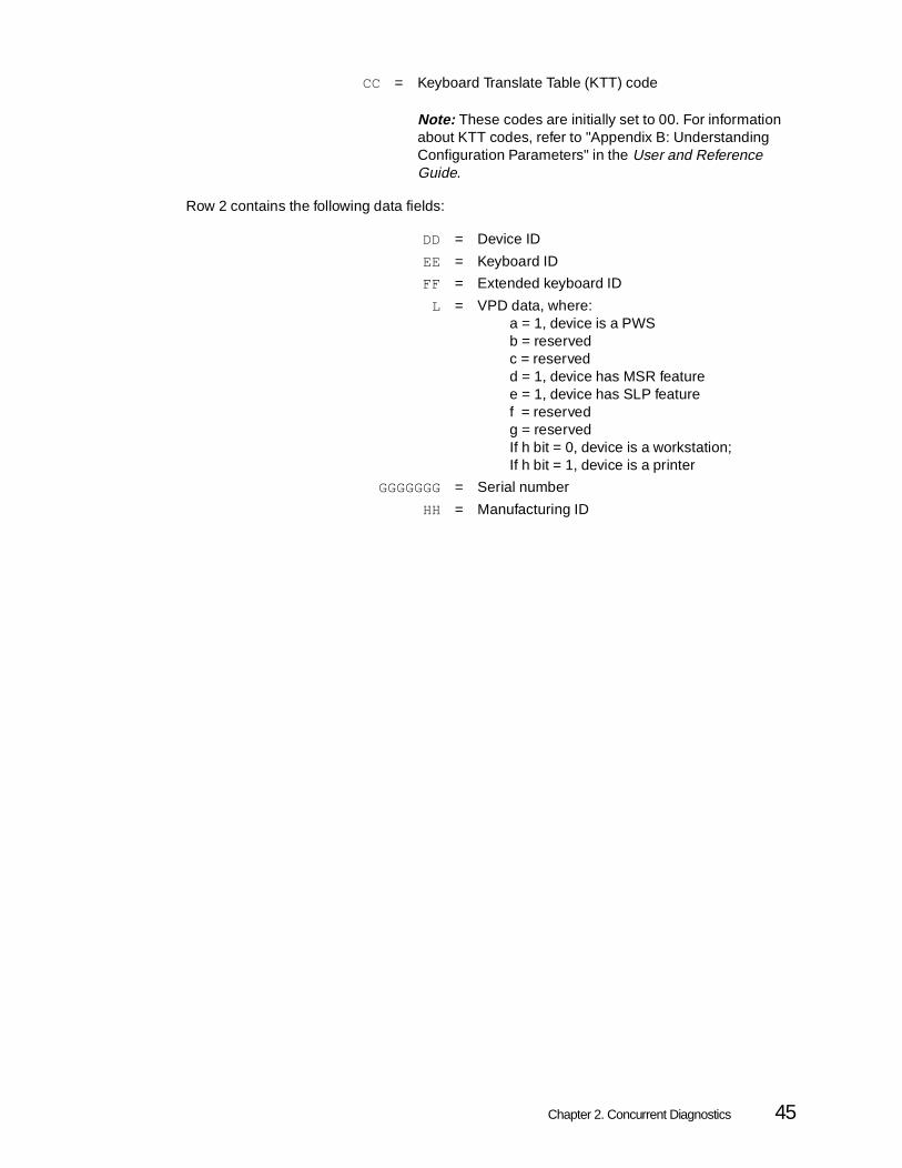
Row 2 contains the following data fields:
CC = Keyboard Translate Table (KTT) code
Note: These codes are initially set to 00. For information about KTT codes, refer to "Appendix B: Understanding Configuration Parameters" in the User and Reference Guide.
DD = Device ID
EE = Keyboard ID
FF = Extended keyboard ID
L = VPD data, where:a = 1, device is a PWSb = reservedc = reservedd = 1, device has MSR featuree = 1, device has SLP featuref = reservedg = reservedIf h bit = 0, device is a workstation;If h bit = 1, device is a printer
GGGGGGG= Serial number
HH = Manufacturing ID
Chapter 2. Concurrent Diagnostics 45

C6 Screen: 594 System Time-Stamped Error Log
The C6 screen displays the 594 time-stamped error log beneath the dashed line. Each entry appearsin a two-row display. Whenever the C6 screen is first displayed, or the display is updated, the newestentry appears at the top of the display. To update the display, press Enter .
Note: For a list of errors that have been sent to the current AS/400 system, either because the 594 was varied off or because the error counters overflowed, use the C1 screen.
To display the previous group of entries, place the cursor on the `– ' next to the screen identifier andpress the Down arrow key.
To display the next group of entries, place the cursor on the ̀ – ' next to the screen identifier and pressthe Up arrow key.
Row 1 displays the following data fields:
Row 2 displays any sense data in the error log entry; it may be blank.
Note: For device errors, the first byte of sense data contains the LSID (Logical Station ID).
QQ = Month the error was logged
RR = Day the error was logged
TT = Hour the error was logged
UU = Minute the error was logged
SS = Second the error was logged
EEEEEE = SRC
40 = (Reserved)
VV = Number of consecutive times that the error has occurred
Line 1Line 2Line 3Line 4
Line 9Line 10
Line 24
----------------------------------------------------------------------------
QQ/RR TT:UU:SS EEEEE 40 VV00 00 00 00 00 00 00 00 00
QQ/RR TT:UU:SS EEEEE 40 VV00 00
QQ/RR TT:UU:SS EEEEE 40 VV00 00 00 00 00 00 00 00 00 00 00 00 00 00 00 00 00 00 00
QQ/RR TT:UU:SS EEEEE 40 VV
C6 - - -
(COMMON DATA FIELDS)
46 Perle 594 Diagnostic Guide

C8 Screen: LAN Gateway Adapter Status Data
When the 594 is using a LAN gateway, the C8 screen displays the LAN gateway adapter status. Whenthe 594 is using a Token-Ring gateway, three rows of data appear, as shown in the illustration. Whenthe 594 is using an Ethernet gateway, the second row is blank.
Row 1 contains the following data fields:
Row 2 is blank when the 594 is communicating over an Ethernet gateway. It contains the followingToken-Ring fields:
Token-Ring fields:FFFFFFFF = Line error count
QQ = Overflow data from the preceding field
GGGGGGGG= Burst error count
HHHHHHHH = Abort Delimiter count
IIIIIIII = Receive Congestion error count
JJJJJJJJ = Frequency error count
Ethernet fields:FFFFFFFF = Transmit error count
QQ = Overflow data from the preceding field
GGGGGGGG= Receive Congestion error count
KKKKKKKK = Internal error count
MMMMMMMM= Access Control (a/c) error count
NNNNNNNN= Lost frame count
OOOOOOOO= Frame Copy error count
PPPPPPPP = Token Error count
Line 1Line 2Line 3Line 4
Line 24
----------------------------------------------------------------------------
FFFFFFFF QQ GGGGGGGG QQ HHHHHHHH QQ IIIIIIII QQ JJJJJJJJ QQKKKKKKKK QQ MMMMMMMM QQ NNNNNNNN QQ OOOOOOOO QQ PPPPPPPP QQ
XXXX YYST RRRR
C8 - -
(COMMON DATA FIELDS)
Chapter 2. Concurrent Diagnostics 47

Row 3 contains the following data fields:
Token-Ring fields:XXXX = (Reserved)
YY = (Reserved)
S = Adapter status, where:0 = closed1 = open
T = Line speed, where:0 = 4 Mbps1 = 16 Mbps
RRRR = Number of active links (000– FFF, in hexadecimal)
Ethernet fields:XXXX = (Reserved)
YY = (Reserved)
S = Adapter status, where:0 = closed1 = open
T = (Reserved)
RRRR = Number of active links (000– FFF, in hexadecimal)
48 Perle 594 Diagnostic Guide

C9 Screen: Link Station Status Data
When the 594 communicates with the AS/400 over a LAN or Frame Relay attachment, the C9 screendisplays data for the active AS/400 Link Station. To display the link station status for the AS/400connection, select C9 1 and press Enter . To display the LAN Gateway link station status, select C92 and press Enter .
The C9 screen displays data about a group of four link stations at a time, for up to 80 Link Stations.If the connection to the AS/400 is not by either Token Ring, Ethernet or Frame Relay, C9 1 will notbe available. If there is no LAN Gateway configured, C9 2 will not be available.
Each C9 screen displays data about four active Link Stations. To scroll through data displays of LinkStations, place the cursor at the `– ' to the right of C9 2 (Line 24 of the illustration), and press the Upor Down arrow key. If there is no ̀ – ' to the right of C9 2, there are no other active Link Stations to bedisplayed.
For Token Ring or Ethernet Link Stations
Data for each link station appears in a three-row display.
Row 1 contains the following data:
Row 2 contains the following data:
BBBB = Link station ID
AA/AA = Link state/LLC (logical link control) state
DD/DD = Link primary state/link secondary state
CCCCCCCCCCC= Token-Ring or Ethernet address
EE = Contents of Response (T1) timer
11 = Network header
Line 1Line 2Line 3Line 4
Line 9
Line 24
----------------------------------------------------------------------------
BBBB AA/AA DD/DD CCCCCCCCCCCC EE11 11 11 11 11 11 11 11 11 11 11 11 11 11 11 11 11 11FFFFFFFF KK GGGGGGGG KK HHHHHHHH KK IIIIIIII KK JJJJJJJJ KK
BBBB AA/AA DD/DD CCCCCCCCCCCC EE11 11 11 11 11 11 11 11 11 11 11 11 11 11 11 11 11 11FFFFFFFF KK GGGGGGGG KK HHHHHHHH KK IIIIIIII KK JJJJJJJJ KK
BBBB AA/AA DD/DD CCCCCCCCCCCC EE11 11 11 11 11 11 11 11 11 11 11 11 11 11 11 11 11 11FFFFFFFF KK GGGGGGGG KK HHHHHHHH KK IIIIIIII KK JJJJJJJJ KK
BBBB AA/AA DD/DD CCCCCCCCCCCC EE11 11 11 11 11 11 11 11 11 11 11 11 11 11 11 11 11 11FFFFFFFF KK GGGGGGGG KK HHHHHHHH KK IIIIIIII KK JJJJJJJJ KK
C9 2 - -
(COMMON DATA FIELDS)
Chapter 2. Concurrent Diagnostics 49

Row 3 contains the following data:
For Frame Relay Link Stations
Data for each link station appears in a three-row display.
Row 1 contains the following data:
Row 2 contains the following data:
Row 3 contains the following data:
FFFFFFFF = Number of I-frames transmitted
KK = Numeric overflow from the preceding field
GGGGGGGG= Number of I-frames received
HHHHHHHH= Transmit error count
IIIIIIII = Receive error count
JJJJJJJJ = Number of times the Response (T1) timer expired
BBBB = Link station ID
AA/AA = Link state/LLC (logical link control) state
CCCC = DLCI
FFFFFFFF = Total number of bytes transmitted
GGGGGGGG= Total number of bytes received
HHHHHHHH= Total number of frames transmitted
IIIIIIII = Total number of frames received
JJJJJJJJ = Number of frames received in error
KKKKKKKK = Number of filtered frames
LLLLLLLL = Number of frames received with BECN
MMMMMMMM= Number of frames received with BECN
NNNNNNNN= Number of frames received with DE
OOOOOOOO= Number of times T1 timer expired
Line 1Line 2Line 3Line 4
Line 9
Line 24
----------------------------------------------------------------------------
BBBB AA/AA CCCCFFFFFFFF GGGGGGGG HHHHHHHH IIIIIIII JJJJJJJJKKKKKKKK LLLLLLLL MMMMMMMM NNNNNNNN OOOOOOOO
BBBB AA/AA CCCCFFFFFFFF GGGGGGGG HHHHHHHH IIIIIIII JJJJJJJJKKKKKKKK LLLLLLLL MMMMMMMM NNNNNNNN OOOOOOOO
BBBB AA/AA CCCCFFFFFFFF GGGGGGGG HHHHHHHH IIIIIIII JJJJJJJJKKKKKKKK LLLLLLLL MMMMMMMM NNNNNNNN OOOOOOOO
C9 2 - -
(COMMON DATA FIELDS)
50 Perle 594 Diagnostic Guide

CA Screen: 594 Concurrent Host Configuration and Status
The CA screen displays the default host table and the current host table for twinaxially-attached displaysand printers.
The default host table displays the host that produces the sign-on screen when the display is firstpowered-on or the host with which printer communicates. The current host table displays the host that iscurrently active.
Since it is possible to have a shared-address display attached to the 594, each address has positions forfour sessions.
The default host table for ports 0 to 7 are displayed at the top of the screen area. The current host tableis displayed at the bottom. The groups of four (i.e. abcd or ABCD) represent one station address. Stationaddresses are 0 to 6.
Sessions "a" and "A" are for the base session of a shared-address display or for the only session of asingle address display. Sessions "b-d" and "B-D" are for the additional shared sessions.
The default host table has an entry for every possible session even though there may be a printer or asingle-session display attached at that address. The current host table displays "0" for any inactivesession. Hosts 1 to 4 are the same hosts configured as H1 to H4.
Note: The default host table displays "1234" for printers configured for printer sharing.
The current host table displays the host number, even if the host is inactive and an error message iscurrently displayed on the user's screen.
Chapter 2. Concurrent Diagnostics 51

CB Screen: Frame Relay Token-Ring Bridge Counters
The CB screen displays the frame relay token-ring bridge configuration information, status, and counters.It is available when FR-TR Bridge is configured.
Note: There is no attempt to display the bridge filter file in concurrent mode. To view the filter file, use any ASCII editor to view the 594FILT.DAT file.
You can use the CB screen to start and stop frame forwarding or to reset the counters to zero. The screendisplays the date and time when the counters were last updated.
To reset the counters, stop or start bridge forwarding, or to refresh the counters, set the switches on line24 as desired, and press Enter .
The lower portion of the screen has two sections. The left side displays information for the token-ring port(port 1) of the bridge. The right side displays information for the frame relay port (port 2) of the bridge.
Screen data is defined as:
Status and Configuration Information:
B = Bridge information
--b-- = Bridge Forwarding Status0 = Stopped1 = Active
n = Bridge Number
pppp = Bridge Priority
aa = Maximum Age BPDUs in seconds
tt = Time between BPDUs in seconds
s = Enable Automatic Spanning Tree Operation0 = No1 = Yes
P1 = Port 1 information for the token-ring port is displayed on the left side of the screen.
52 Perle 594 Diagnostic Guide

Counters:
Note: If "+" follows any counter, the counter has overflowed.
P2 = Port 2 information for the frame relay port is displayed on the right side of the screen.
--p-- = STE Frame Forwarding status0 = Stopped1 = Active
nnn = Port Ring Number
ssssss = Port Speed
h = Port Hop Count
f = Forward Spanning Tree Explorer frames on this port0 = No1 = Yes
AAA BBB = First two frame relay token-ring bridge DLCIs (displayed if configured)
aaaaaaaaaaaa = Frame Relay MAC Address
CCC DDD = Last two frame relay token-ring bridge DLCIs (displayed if configured)
Outbound Frames Summary
1a1a1a1a = Transmitted
1b1b1b1b = Normal Discards
1c1c1c1c = Error Discards
Inbound Frames Summary
2a2a2a2a = Received
2b2b2b2b = Normal Discards
2c2c2c2c = Error Discards
Outbound Frames Transmitted
3a3a3a3a = All Routes Explorer
3b3b3b3b = Spanning Tree Explorer
3c3c3c3c = Specifically Routed Frames
Outbound Bytes Transmitted
4a4a4a4a = All Routes Explorer
4b4b4b4b = Spanning Tree Explorer
4c4c4c4c = Specifically Routed Frames
Outbound Frames Normal Discards
5a5a5a5a = Filtered
Outbound Frames Error Discards
6a6a6a6a = Transmit Delay Exceeded
6b6b6b6b = Congestion
6c6c6c6c = Maximum Frame Size Exceeded
6d6d6d6d = Target Segment Inoperative
Chapter 2. Concurrent Diagnostics 53

Last Line:
6e6e6e6e = Nonspecific
Inbound Frames Received
7a7a7a7a = All Routes Explorer
7b7b7b7b = Spanning Tree Explorer
7c7c7c7c = Specifically routed frames
Inbound Frames Normal Discards
8a8a8a8a = Filtered
8b8b8b8b = Hop count exceeded
Inbound Frames Error Discards
9a9a9a9a = Congestion
9b9b9b9b = Invalid routing information
9c9c9c9c = SRF Duplicate segment
9d9d9d9d = STE Duplicate segment
9e9e9e9e = STE or ARE Segment mismatch
9f9f9f9f = Nonspecific
CB = Panel identifier
W = Enable/Disable Bridge0 = Do not change forwarding status
1 = Start Frame Forwarding2 = Stop Frame Forwarding
Y = Counter reset for port 1 (Token-Ring)0 = Do not reset1 = Reset counters to zero
Z = Counter reset for port 2 (Frame Relay)0 = Do not reset1 = Reset counters to zero
Note: Switches W, Y, and Z are reset to zero after the Enter key is pressed.
yy/mm/dd = Date in year, month, day format of the last screen refresh
hh:mm:ss = Time in hour, minute, second format of the last screen refresh
54 Perle 594 Diagnostic Guide
Displaying Concurrent Diagnostics Data On the 594 Operator Panel
The front panel requests display Concurrent Diagnostic data on the 594 operator panel. Each panel isidentified by the request number (see “Summary of Concurrent Diagnostics Requests” on page 57).
Whenever a Request command retrieves more than 12 bytes of data, the data appears in a series ofpanels that is displayed in a continuous loop. Each panel in a series is identified by both the requestnumber and a two-character panel number. The format of the panel number depends on both thecommunications method and the Request command being used.
To navigate a series of panels:
• Use the Up arrow key to display the next panel of the series. When the LCD is already showing thelast panel of the list, pressing the Up arrow key displays an End of List indicator (if any) or (in the eventthat there is no End of List indicator), the first data panel of the series.
• Use the Down arrow key to display the previous panel of the series. When the LCD is already showingthe first data panel of the series, pressing the Down arrow key displays the End of List indicator or,(in the event that there is no End of List indicator) the last data panel of the series.
To display configuration and status data from the 594 operator panel while the 594 is on-line:
Step 1 Press the Req key on the operator panel.
Step 2 Type the Request number that displays the data you need.
Note: Tables in the "Summary of Concurrent Diagnostics Requests" and "Locating theConcurrent Diagnostics Data That You Need" sections describe the dataretrieved by using Concurrent Diagnostic Request commands, and relateretrievable data to panel identifiers.
Step 3 Press Enter .
Step 4 Use the panel descriptions on the following pages to help you interpret the data.
Note: Status data appearing on the operator panel is retrieved when you issue theRequest command and displayed until you either issue another command orclear the LCD. To update the data, repeat steps 1– 3.
Step 5 When you have finished viewing the data, either issue a new request or press Esc .
Chapter 2. Concurrent Diagnostics 55

Selecting a controller
Whenever the 594 is in enhanced mode, the data retrieved by Concurrent Diagnostic Request commandsprovides data about a specific controller. The top line of the LCD shows the controller (CP) name.Whenever you want information about a different controller, you need to change the controller name thatappears on the LCD.
To select a new controller when the Perle 594 is in enhanced mode:
Step 1 Press Ctrl .
The controller name is set off by solid triangles at either end of the top line, and the data area of the bottom line is filled with asterisks.
Step 2 Use the Up or Down arrow key to locate the controller you want.
Note: The list of controllers does not appear in a continuous loop.
Step 3 Press Enter to display data for the controller shown on the top line of the LCD.
Note: You can now use the Up and Down arrow keys to scroll through a series of datapanels.
Step 4 Press Esc to return to viewing the data for the previously selected controller.
Note: You can now use the Up and Down arrow keys to scroll through the series of datapanels that were displayed before you pressed the Ctrl key.
56 Perle 594 Diagnostic Guide

Summary of Concurrent Diagnostics Requests
Concurrent Diagnostics data is displayed, upon request, on the two-line LCD. The top line identifies thedevice for which data is displayed. The 594e in compatible mode, the top line displays "Perle 594e". Withthe 594 in enhanced mode, the top line displays the controller (CP) name. The bottom line displays therequested data.
There are 12 requests (200 through 211) that retrieve configuration and status data while the 594 ison-line. The following table lists the kind of data retrieved by each command.
Request Description
200 Display 594 Online Status Information (page 58)
201 Display 594 Configuration Information (page 60)
202 Display AS/400 Link Communication Configuration Information (page 66)
203 Display 594 Error Log Entries (page 76)
204 Display Transmit Activity Check (TAC) and parity timeout error counts (page 77 )
205 Display 594 Communications Error and Statistical Counter (page 77
206 Display 594 Communication State Byte (page 86)
207 Display 594 SNA State Byte (page 92)
208 Display 594 Communication Interface Register (page 93)
209 Display 594 LAN Gateway Statistical Counters (page 96)
210 Display 594 Twinax or ASCII on-line device Information (page 97)
211 Display 594 LAN Gateway on-line device Information (page 100)
215 Display Status and configuration Information of Concurrent Host Attachment (page 100)
216 Display 594 LAN Card permanent address (page 102)
217 Display 594 FR-TR Bridge Counters for the Token-Ring port (page 103)
218 Display 594 FR-TR Bridge Counters for the Frame Relay port (page 103)
219 Reset 594 FR-TR Bridge Counters for the Token-Ring port (page 104)
220 Reset 594 FR-TR Bridge Counters for the Frame Relay port (page 104)
240 Start/Stop 594 FR-TR Bridge frame forwarding. (page 104)
241 Start/Stop 594 IP Router frame forwarding (page 105)
250 Display 594 IP Router Configuration Information (page 105)
251 Display 594 IP Router Counters (page 105)
252 Reset 594 IP Router Counters (page 106)
253 Display 594 IP Router Port Configuration Information (page 106)
254 Display 594 IP Router Port Counters (page 107)
255 Reset 594 IP Router Port Counters (page 108)
256 Display 594 IP Router Static Route Table (page 109)
257 Display 594 IP Router Frame Relay IP DLCI Table Information (page 110)
258 Display 594 IP Router Dynamic Route Table (page 110)
Chapter 2. Concurrent Diagnostics 57

Req 200: AS/400 Link or LAN Link Status
Using the Request 200 command retrieves AS/400 link status data. The format of the data display for the594e depends on whether it is in compatible or enhanced mode. The format of the data display for the594T is the same as compatible mode.
Compatible Mode (Perle 594e only)
A single panel shows whether each 594e communications card was engaged, at the time of therequest, in communicating with at least one attached device. Each identifier is followed by an arrowthat indicates whether the identified communication state was established or not at the time of therequest.
200||1↑2↑3 ↓4↑5↑ where:
Note: When there are link status changes after the request was made, the display is not automatically updated. To update the display, press Req, type 200, and press Enter .
1 = Is the Perle 594 communicating with the Adjacent Link Station (ALS)?
↑= Yes ↓= No
2 = Is the Perle 594 communicating with at least one twinaxial workstation?
↑= Yes ↓= No
3 = Is the Perle 594 communicating with at least one LAN workstation?
↑= Yes ↓= No
4 = Is the Perle 594 communicating with the selected AS/400 system?
↑= Yes ↓= No
5 = Has the Perle 594 fully established a logical connection (an LU 6.2 controller session) with the selected AS/400?
↑= Yes ↓= No
58 Perle 594 Diagnostic Guide

Enhanced Mode
When the Perle 594 is in enhanced mode and you request network communication status data, three pan-els are required to show the status of all 594 communications cards.
Note: To display the card identifiers for each slot, use Req 201 and scroll to Panels 201-P1 through 201-P3.
The first two panels show the status of each 594 interface card.
200-01|| 1↑2↑3↓4↑ Status of cards in slots 1 through 4
200-02|| 5↓6↓7↑ Status of cards in slots 5 through 7
• The indicator shows whether there is communications activity on the feature card.↑ = Yes↓ = No
• When the card in the identified slot is used for AS/400 system communications, the indicator shows whether the 594 has established communication with the ALS?↑ = Yes↓ = No
200-03|| 8↑ 9↑ Status of the selected controller
Note: When there are link status changes after the request was made, the display is not automatically updated. To update the display, press Req, type 200, and press Enter .
8 = Is the selected controller communicating with theselected AS/400 system?
↑= Yes ↓= No
9 = Has the selected controller established a logicalconnection (an LU 6.2 controller session) with theselected AS/400 system?
↑= Yes ↓= No
Chapter 2. Concurrent Diagnostics 59

Req 201- 01 to 201-14, 201-15: AS/400 and LAN Link Configuration Data
Using a Request 201 command retrieves configuration data for the current communications link.
Whenever the current connection is a Token-Ring or Ethernet, there are additional panels. For anexplanation of these panels, refer to the following section, "Req 201-16—201-20: LAN Gateway AdapterConfiguration and Status Details."
Panels 201-P1 through 201-P3 appear at the end of the series. For an explanation of these panels, referto the section, "Req 201-P1—201-P3: Controller Configuration and Status Details."
201-01|| sssdc a b Current AS/400 system data, where:
201-02||ccx ii aa Retry limits configured for the selected link, where:
201-03|| nnnnnnnn 594 network name
sss = Motherboard RAM storage size, in megabytes
d = 594 Date and Time synchronizationA = set the 594 date and time from the primary AS/400
date and timeC = 594 date and time set at the controller only
c = Communication method, where:0 = SDLC1 = X.252 = X.21 Switched3 = X.21 Leased4 = Token-Ring5 = Ethernet6 = Frame Relay7 = Frame Relay Token-Ring BridgeA = Frame Relay IP RouterB = Frame Relay IP Router and Token-Ring BridgeD = Async PPP IP Router
a = Current AS/400 system (1– 4)
b = Network protocol, where:0 = standard SNA1 = TCP/IP
cc = Maximum number of times that the 594 can try to establish a logical connection before an error is generated
x = Is the logical connection configured for continuous retriesat 10-minute intervals?
↑= Yes ↓= No
ii = Logical connection retry interval (00– 1C seconds, in hexadecimal)
aa = SDLC or LLC address
Note: When the connection is Token-Ring, Ethernet or Frame Relay, this field is blank.
60 Perle 594 Diagnostic Guide

201-04|| llllllll 594 logical unit (LU) name
201-05|| cccccccc 594 remote control point (CP) name
201-06|| pppppppp 594 mode name
201-07|| hhhhhhhh AS/400 network name
201-08|| uuuuuuuu AS/400 logical unit (LU) name
201-09||vvvv mmyy 594 release and version data in the following format, where:
201-10||ccc xxxxx Cable connecting the 594 to the AS/400 system, where:
201-13||ss-sssss 594 serial number
201-14||md i jjj Host configuration data, where:
vvvv = Current 594 system version
For example: 0220 represents Version 2.2.
mmyy = Month and year that the system files were released
000 = X.21 DTE
001 = V.35 DTE
010 = V.24 DTE
011 = No cable
100 = X.21 DCE
101 = V.35 DCE
110 = V.24 DCE
111 = Loopback
xxxxx = XID block number. If there is no XID block number configured, * will be displayed.
m = Indicates when the controller session with the currentlyselected AS/400 will be started, where:
0 = At power on of first NWS or PWS1 = Immediately after power on of the 594 controller.
d = Controller session termination activity when the currentlyselected AS/400 indicates there are no NWS sessions,where:
0 = Controller session will be terminated, unless there is a PWS session that is active or there is an active controller session with another host.1 = Controller session will not be terminated.
i = Status of concurrent host attachment, where:0 = Concurrent host attachment is not configured.1 = Concurrent host attachment is configured.
Chapter 2. Concurrent Diagnostics 61

201-15||mmdd ijss LAN workstation configuration data, where:
jjj = Printer timeout value. If concurrent host attachment is configured, this represents the number of seconds the 594 controller will wait before accepting a print job from another host.
Note: If jjj is set to zero, printer sharing is disabled.
mm = Maximum number of workstations that can be connectedto the Perle 594 (00– FF, in hexadecimal)
dd = The LAN gateway type configured for the AS/400 system,where:
00 = (none)01 = Token-Ring02 = Ethernet
i = LAN Adapter status, at the time of the request, where:0 = Closed or not configured1 = Open
j = Configured Token-Ring gateway speed, where:0 = 4 Mbps1 = 16 Mbps
Note: This field is blank when the LAN gateway type isnot configured (dd=00), or is configured as Ethernet (dd=02).
ss = 594 LAN gateway Service Access Point (SAP), in hexadecimal
Note: This field appears only when a LAN gateway is configured.
62 Perle 594 Diagnostic Guide

Req 201-16 to 201-20: LAN Gateway Adapter Configuration and Status Details
When the current connection is a Token-Ring or Ethernet, using a Request 201command displays LANgateway configuration details on Panels 201-16 through 201-20. To determine whether the connectionis a LAN gateway, display Panel 15. If dd = 00, panels 201-16 and 201-20 do not appear.
Similarly, if the Frame Relay Token-Ring Bridge is not configured, Panels 201-21 through 201-30 do notappear.
201-16||a tttttt* The first half of the 594 LAN address, where:
201-17|| *tttttt The remainder of the 594 LAN address
201-18||rr ii aa Timeout configurations, where:
201-19||cc oo mm Retry configurations, where:
201-20|| ffff When the gateway is not Ethernet, this panel does not appear. When the gateway is Ethernet, this panel displays the configured frame format, which indicates the Ethernet type and version being used, where:
a = When the gateway is Ethernet:E = Address is in Ethernet formatT = Address is in Token-Ring format
Note: When the gateway is Token-Ring, this field is blank.
tttttt = The first six digits of the 594 LAN address
rr = Response timer (T1): Amount of time allowed for the 594 to wait for an acknowledgment or response from the LAN (01– 14 seconds, in hexadecimal)
ii = Inactivity timer (Ti): Amount of time allowed for the 594 to detect a LAN error condition (01– 63 seconds, in hexadecimal)
aa = Receive Acknowledgment timer (T2): Amount of time allowed for the 594 to send acknowledgments to the LAN (01– FF seconds, in hexadecimal)
cc = Retry Count (N2): Maximum number of retries allowed for the 594 to establish an AS/400-to- LAN workstation connection, following Response Timer (T1) expiration (00– FF times, in hexadecimal)
oo = Maximum Out (TW): Maximum number of information frames that the 594 can send before receiving acknowledgment (02– 08 frames)
mm = Maximum In (N3): Maximum number of information frames that the 594 can receive before sending acknowledgment (01– 04 frames)
8023 = Ethernet 802.3
V2 = DIX Ethernet Version 2.0
AUTO Auto configure
Chapter 2. Concurrent Diagnostics 63

Req 201-21 to 201-30: Frame Relay Token-Ring Bridge Configuration Data
Note: When Frame Relay Token-Ring Bridge is not configured, Panels 201-21 through 201-30 do not appear.
201-21|| ttt fff FR-TR LAN numbers, where:
201-22|| ssssssss LAN Ring speed, where:
201-23|| sssss Frame Relay line speed, where:
201-24|| aaaaaa* Frame Relay Virtual LAN MAC address, where:
201-25|| *aaaaaa Frame Relay Virtual LAN MAC address, where:
201-26||dddd dddd FR-TR Bridge DLCIs, where:
201-27||dddd dddd
201-28||bb pppp FR-TR Bridge number, where:
201-29||mm tt l FR-TR Bridge configuration data, where:
ttt = LAN ring number (001– FFF)
fff = Frame Relay virtual LAN ring number (0001– FFF, in hexidecimal)
ssssssss = LAN ring speed (2580– F42400, in hexadecimal)
sssss = Frame Relay line speed (2580– 1F400, in hexadecimal)
aaaaaa* = First six digits of the Frame Relay MAC address.Go to panel 25 to see the remainder of the address. (400000000000– 7FFFFFFFFFFF)
*aaaaaa = Last six digits of the Frame Relay MAC address. (400000000000– 7FFFFFFFFFFF)
dddd = One to four DLCIs used for the FR-TR bridge. If one or two are configured, panel 27 is not displayed. (1– 3FF, in hexadecimal)
bb = Bridge number (0– 15, in hexadecimal)
pppp = Bridge priority (0001– FFFF, in hexadecimal)
mm = Maximum age BPDU (6– 28 seconds, in hexadecimal)
tt = Time period between BPDUs (1-A seconds, in hexadecimal)
l = Status of bridge frame forwarding0=Frame forwarding disabled1=Frame forwarding enabled
64 Perle 594 Diagnostic Guide

201-30||a nr llff FR-TR Bridge configuration data, where:
Req 201-31 594 Network Controller Feature Information (Perle 594e only)
This request is used to display any 594 network controller feature information
201-31||bb 594 Network Controller Information where:
Req 201-P1 to 201-P3: Feature Card Configuration
Panels 201-P1 through 201-P3 appear at the end of the series of Request 201 panels. These panelsshow the card identifier used by the card in each slot. Slot 1 always holds the SynchronousCommunication Card. Values for slots 2 through 7 can be any of the following:
201-P1||aa bb cc Card identifiers for slots 1 through 3, where:
a = Enable Automatic Spanning Tree Operation0=Disabled1=Enabled
n = Forward Spanning Tree Explorer frames by LAN port0=Disabled1=Enabled
r = Forward Spanning Tree Explorer frames by Frame Relay port0=Disabled1=Enabled
ll = Hop Count for LAN port (1– 7)
ff = Hop Count for Frame Relay port (1– 7).
bb = 594 Hard Drive information where:00=Disabled01=Enabled
00 = Empty slot
96 = Synchronous Communication Card (594e)
97 = Synchronous Communication Card (594T)
41 = Twinaxial Feature Card (594e)
42 = ASCII Feature Card (594e)
43 = Token-Ring Feature Card
44 = DBCS Twinaxial Feature Card (594e)
45 = Ethernet Feature Card
48 = Twinaxial Feature Card
49 = Fast Ethernet Feature Card
aa = Card identifier for slot 196 for 594e97 for 594T
bb = Card identifier for slot 2
cc = Card identifier for slot 3
Chapter 2. Concurrent Diagnostics 65

201-P2||aa bb cc Card identifiers for slots 4 through 6 apply to the 594e only, where:
201-P3||aa Card identifier for slot 7 (594e only)
Req 202-11 to 202-76: AS/400 link configuration data
Using a Request 202 command retrieves protocol configuration data for the current AS/400 systemattachment. The format of the display is the same for compatible and enhanced modes and depends onthe communication method selected at the time of the request.
Data appears in a series of panels. Each panel number cy indicates the communication method and thepanel number, where:
c = Communication method, where:1 = SDLC or X.21 Leased2 = X.253 = X.21 Switched4 = Token-Ring5 = Ethernet6 = Frame Relay 7 = Async PPP
y = Panel identifier (1– 9)
Req 202-11: AS/400 SDLC or X.21 Leased Attachment Settings
Whenever the 594 is connected to the AS/400 system through an SDLC or X.21 Leased attachment,using a Request 202 command displays link protocol configuration data on a single panel.
202-11||sdmn cpl Basic configuration data, where:
aa = Card identifier for slot 4
bb = Card identifier for slot 5
cc = Card identifier for slot 6
s = Line type, where:0 = Leased1 = Switched/Manual2 = Switched/V.25 BIS
d = Line facility, where:0 = Half-duplex1 = Duplex
m = Connection type, where:0 = Multipoint1 = Point-to-point
n = Data encoding method, where:0 = NRZI (Non-Return to Zero Inverted)1 = NRZ (Non-Return to Zero)
c = Connection method, where:0 = DTR (Data Terminal Ready)1 = CDSTL (Connect Data Set To Line)
66 Perle 594 Diagnostic Guide

Note: When there are link status changes after the request was made, the display is not automatically updated. To update the display, press Req, type 202, and press Enter .
Req 202-21 to 202-23: AS/400 X.25 Attachment Settings
Whenever the 594 is communicating with an AS/400 system over an X.25 attachment, using a Request202 command displays link protocol configuration data on a series of panels. Fixed values are shown asthey appear in the display.
202-21||m pl ssss Packet-level configuration data, where:
202-22||v fmlr cc Hardware-related configuration data, where:
p = Is a Send Leading Pad byte required before theSDLC flag, for synchronization?
0 = No1 = Yes
l = Is local loopback supported?0 = No1 = Yes
m = Packet-level sequence numbering, where:0 = Modulo 81 = Modulo 128
p = Packet window size (2– 7)
l = Link window size (1– 7)
ssss = Packet size (0064, 0128, 0256, 0512, or 1024)
v = Virtual circuit type, where:0 = Multiple PVCs, SVCs, or SVC call allowed1 = PVC only2 = SVC answer only
f = Flow control negotiation, where:0 = Not permitted1 = Permitted
m = Manual options, where:0 = Not permitted1 = Permitted
l = Local loopback, where:0 = Not permitted1 = Permitted
r = Reverse charging, where:0 = Not permitted1 = Permitted
cc = Logical link control (LLC) selection, where:00 = QLLC (Qualified Logical Link Control) 01 = ELLC (Enhanced Logical Link Control)
Chapter 2. Concurrent Diagnostics 67

202-23||uisd cctt Communication protocol configuration data, where:
Note: When there are link status changes after the request was made, the display isnot automatically updated. To update the display, press Req, type 202, and pressEnter .
Req 202-31 to 202-33: AS/400 X.21 Switched Attachment Settings
Whenever the 594 is connected to the AS/400 system through an X.21 Switched link, using a Request202 command retrieves both protocol configuration data and AS/400 attachment status data. There maybe one, two or three panels of data, depending on the number of Call Progress Signals (CPSs) to bedisplayed. The following table describes each CPS.
202-31||ccds cpcp Configuration data, and the first CPS, if any, where:
u = Telenet** type network attachment, where:0 = Not supported1 = Supported
i = Link initiation, where:0 = Either 594 or X.25 network1 = X.25 network only
s = X.25 network subscription, where:0 = 1988 subscription1 = 1984 subscription2 = 1980 subscription
d = Diagnostic codes, where:0 = 1984/1988 SNA1 = 1984/1988 ISO2 = 1980 SNA
cc = Retry Count (N2): Maximum number of retries allowed to establish a logical attachment (LU 6.2 controller session) with the AS/400 system, following expiration of the Inactivity Timer (Ti) (00– FF times, in hexadecimal)
tt = Retry interval: Amount of time that the 594 must wait between attempts to establish a controller session (00– 3C seconds, in hexadecimal)
cc = Recall counter (00– FF seconds, in hexadecimal)
d = Recall delay time (1– F seconds, in hexadecimal)
s = Is Short Hold Mode (SHM) reconnection tothe AS/400 by direct call supported?
0 = No1 = Yes
cp = Optional CPS
Note: A single-digit CPS is not displayed with a leading 0; it is either preceded or followed by an underscore. For example, _5 or 5_ represents a 05 CPS.
68 Perle 594 Diagnostic Guide

202-32||cpcp cpcp and 202-33||cpcp cpcp
There may be up to two additional panels, displaying up to two CPSs each.
Note: When there are link status changes after the request was made, the display isnot automatically updated. To update the display, press Req, type 202, and pressEnter .
Call Process Signal (CPS) Codes
Any of the following CPSs may appear on Panels 202-31 through 202-33:
Req 202-41 to 202-48: AS/400 Token-Ring Attachment Settings
Whenever the 594 is connected to the AS/400 system over a Token-Ring attachment, using a Request202 command retrieves LAN link station configuration data.
202-41|| hhhhhh* AS/400 system Token-Ring address (first six bytes)
202-42|| *hhhhhh AS/400 system Token-Ring address (last six bytes).
202-43||ss AS/400 system Service Access Point (SAP)
202-44|| jjjjjj* Perle 594 Token-Ring address (first six bytes)
202-45|| *jjjjjj Perle 594 Token-Ring address (last six bytes)
202-46||ss Perle 594 SAP, in hexadecimal (04, 08,... FC).
202-47||rr ii aa Timer configurations, where:
01 = Terminal Called 45 = Controlled Not Ready
02 = Redirected Call 46 = Uncontrolled Not Ready
03 = Connect When Free 47 = DCE Power Off
04 = Private Network Reached 48 = Invalid Facility Request
05 = Public Network Reached 49 = Network Fault in Local Loop
41 = Access Barred 51 = Call Information Service
42 = Changed Number 52 = Incomplete User Class of Service
43 = Not Obtainable 71 = Long-term Network Congestion
44 = Out of Order 72 = RPOA Out of Order
rr = Response timer (T1): Amount of time that the 594 can wait for an acknowledgment or response from the network (01– 14 seconds, in hexadecimal)
ii = Inactivity timer (Ti): Amount of time allowed for the 594 to detect an error condition (01– 63 seconds, in hexadecimal)
aa = Receive Acknowledgment timer (T2): Amount of time allowed to make sure that the 594 sends acknowledgments (1– FF seconds, in hexadecimal)
Chapter 2. Concurrent Diagnostics 69

202-48||nn oo pp Retry configurations, where:
Req 202-41 to 202-48: AS/400 TCP/IP Token-Ring Attachment Settings
Whenever the 594 is connected to the AS/400 system over a TCP/IP Token-Ring attachment, using aRequest 202 command retrieves LAN link station configuration data.
202-41|| hhhhhh* AS/400 system Token-Ring address (first six bytes). If the display shows all zeros, then the LAN Address is not available.
202-42|| *hhhhhh AS/400 system Token-Ring address (last six bytes). If the display shows all zeros, then the LAN Address is not available.
202-44|| jjjjjj* Perle 594 Token-Ring address (first six bytes)
202-45|| *jjjjjj Perle 594 Token-Ring address (last six bytes)
202-P1|| jjj.jjj.* 594 IP address (first half)
202-P2|| *jjj.jjj 594 IP address (first half)
202-P3|| jjj.jjj.* AS/400 IP address (first half)
202-P4|| *.jjj.jjj AS/400 IP address (last half)
202-P5|| jjj.jjj.* Network (subnet) mask (first half)
202-P6|| *.jjj.jjj Network (subnet) mask (last half)
202-P7|| jjj.jjj.* Default gateway IP address (first half)
202-P8|| *.jjj.jjj Default gateway IP address (last half)
202-P9|| kk AnyNet Keep Alive duration
nn = Retry Count (N2): Maximum number of times that the 594 can attempt to establish a logical connection (LU 6.2 controller session) to the AS/400, following expiration of the Inactivity Timer (Ti) (00– FF times, in hexadecimal)
oo = Maximum Out (TW): Maximum number of information frames that the 594 can send before receiving acknowledgment (02– 08 frames)
pp = Maximum In (N3): Maximum number of information frames that the 594 can receive before sending acknowledgment (01– 04 frames)
70 Perle 594 Diagnostic Guide

Req 202-51 to 202-59: AS/400 Ethernet Attachment Settings
Whenever the 594 is connected to the AS/400 system over an Ethernet attachment, using a Request202 command retrieves LAN link station configuration data.
202-51||a hhhhhh* AS/400 Ethernet LAN address information, where:
202-52|| *hhhhhh AS/400 Ethernet LAN address (last six bytes)
202-53||ss AS/400 system Service Access Point (SAP), in hexadecimal
202-54||a jjjjjj* Perle 594 Ethernet address information, where:
202-55|| *jjjjjj Perle 594 Ethernet address (last six bytes)
202-56||ss Perle 594 SAP, in hexadecimal (04, 08,... FC).
202-57||rr ii aa 594-to-LAN attachment timer configurations, where:
202-58||nn oo pp 594-to-LAN attachment retry configurations, where:
a = AS/400 address format, where:T = Token-RingE = Ethernet
hhhhhh = Perle 594 Ethernet LAN address (first six bytes)
a = 594 address format, where:T = Token-RingE = Ethernet
jjjjjj = Perle 594 Ethernet address (first six bytes)
rr = Response timer (T1): Amount of time that the 594 can wait for an acknowledgment or response from the network (01– 14 seconds, in hexadecimal)
ii = Inactivity timer (Ti): Amount of time allowed for the 594 to detect an error condition (01– 63 seconds, in hexadecimal)
aa = Receive Acknowledgment timer (T2): Amount of time allowed to make sure that the 594 sends acknowledgments (1– FF seconds, in hexadecimal)
nn = Retry Count (N2): Maximum number of times that the 594 can attempt to establish a logical connection (LU 6.2 controller session) to the AS/400, following expiration of the inactivity timer Ti (00– FF times, in hexadecimal)
oo = Maximum Out (TW): Maximum number of information frames that the 594 can send before receiving acknowledgment (02– 08 frames)
pp = Maximum In (N3): Maximum number of information frames that the 594 can receive before sending acknowledgment (01– 04 frames)
Chapter 2. Concurrent Diagnostics 71

202-59|| ffff Ethernet frame format, where:
Req 202-51 to 202-59: AS/400 TCP/IP Ethernet Attachment Settings
Whenever the 594 is connected to the AS/400 system over a TCP/IP Ethernet attachment, using aRequest 202 command retrieves LAN link station configuration data.
202-51||a hhhhhh* AS/400 Ethernet LAN address information, where:
202-52|| *hhhhhh AS/400 Ethernet LAN address (last six bytes). If the display shows all zeros, then the LAN Address is not available.
202-54||a jjjjjj* Perle 594 Ethernet address information, where:
202-55|| *jjjjjj Perle 594 Ethernet address (last six bytes)
202-59|| ffff Ethernet frame format, where:
202-P1|| jjj.jjj.* 594 IP address from configuration (first half)
202-P2|| *jjj.jjj 594 IP address from configuration (last half)
202-P3|| jjj.jjj.* AS/400 IP address from configuration (first half)
202-P4|| *jjj.jjj AS/400 IP address from configuration (last half)
202-P5|| jjj.jjj.* Network (subnet) mask (first half)
202-P6|| *jjj.jjj Network (subnet) mask (last half)
202-P7|| jjj.jjj.* Default gateway IP address (first half)
202-P8|| *jjj.jjj Default gateway IP address (last half)
202-P9|| kk AnyNet Keep Alive duration
8023 = Ethernet 802.3
V2 = DIX Ethernet Version 2.0
AUTO = Auto configure
a = AS/400 address format, where:T = Token-RingE = Ethernet
hhhhhh = Perle 594 Ethernet LAN address (first six bytes). If the display shows all zeros, then the LAN Address is not available.
a = 594 address format, where:T = Token-RingE = Ethernet
jjjjjj = Perle 594 Token-Ring address (first six bytes)
SNAP = Frame type
V2 = Ethernet Type 2.
72 Perle 594 Diagnostic Guide

Req 202-61 to 202-65: AS/400 Frame Relay Attachment Settings
202-61||sdmn cpl Basic configuration data, where:
202-62||ddd aa ss Basic configuration data, where:
202-63||l pp ff Basic configuration data, where:
202-64||rr ii aa Basic configuration data, where:
202-65||rr mm ii Basic configuration data, where:
s = 0 = Leased
d = 1 = Full Duplex
m = 1 = Point-to-point
n = Data encoding method, where:0 = NRZI (Non-Return to Zero Inverted)1 = NRZ (Non-Return to Zero)
c = 0 = DTR (Data Terminal Ready)
p = 0 = No leading pad required
l = 0 = No local loopback is supported
ddd = Data Link Connection Identifier (DLCI)
aa = AS/400 Service Access Point (SAP)
ss = 594 SAP
l = LMI mode, where:0 = No LMI1 = ANSI, Annex D2 = CCITT
pp = Polling interval (POLLITV) in seconds
ss = Full inquiry interval (FULLINQITV) in cycles
rr = Response timer (T1) in seconds
ii = Inactivity timer (Ti) in seconds
aa = Receiver acknowledgment timer (T2) in milliseconds
rr = Retry count (N2)
mm = Maximum frames out (TW)
ii = Maximum frames in (N3)
Chapter 2. Concurrent Diagnostics 73

Req 202-61 to 202-65: AS/400 TCP/IP Frame Relay Attachment Settings
202-61||sdmn cpl Basic configuration data, where:
202-63||l pp ff Basic configuration data, where:
202-64||rr ii aa Basic configuration data, where:
202-65||rr mm ii Basic configuration data, where:
202-P1|| jjj.jjj.* 594 IP address from configuration (first half)
202-P2|| *jjj.jjj 594 IP address from configuration (last half)
202-P3|| jjj.jjj.* AS/400 IP address from configuration (first half)
202-P4|| *jjj.jjj AS/400 IP address from configuration (last half)
202-P5|| jjj.jjj.* Network (subnet) mask (first half)
202-P6|| *jjj.jjj Network (subnet) mask (last half)
202-P7|| jjj.jjj.* Default gateway IP address (first half)
202-P8|| *jjj.jjj Default gateway IP address (last half)
202-P9|| kk AnyNet Keep Alive duration
s = 0 = Leased
d = 1 = Full Duplex
m = 1 = Point-to-point
n = Data encoding method, where:0 = NRZI (Non-Return to Zero Inverted)1 = NRZ (Non-Return to Zero)
c = 0 = DTR (Data Terminal Ready)
p = 0 = No leading pad required
l = 0 = No local loopback is supported
l = LMI mode, where:0 = No LMI1 = ANSI, Annex D2 = CCITT
pp = Polling interval (POLLITV) in seconds
ss = Full inquiry interval (FULLINQITV) in cycles
rr = Response timer (T1) in seconds
ii = Inactivity timer (Ti) in seconds
aa = Receiver acknowledgment timer (T2) in milliseconds
rr = Retry count (N2)
mm = Maximum frames out (TW)
ii = Maximum frames in (N3)
74 Perle 594 Diagnostic Guide

Req 202-71 to 202-76: TCP/IP Async PPP Attchment Settings
202-71||ssss Basic configuration data, where:
202-72||iiii Basic configuration data, where:
202-73||c p Basic configuration data, where:
202-74||aaaa Basic configuration data, where:
202-75||v p a Basic configuration data, where:
202-76||l Basic configuration data, where:
202-P1||jjj.jjj* 594 ip address (1st half)
202-P2||*jjj.jjj (2nd half)
202-P3||jjj.jjj* as/400 ip address (1st half)
202-P4||*jjj.jjj (2nd half)
202-P5||jjj.jjj* network mask (1st half)
202-P6||*jjj.jjj (2nd half)
202-P7||jjj.jjj* default gateway (1st half)
202-P8||*jjj.jjj (2nd half)
202-P9||kk anynet keep alive duration
ssss = 1152 speed (fixed)
iiii = Inactivity timer in seconds
c = authentication type chap
p = authentication type pap
aaaa = ascii control character
v = vjc compression type
p = protocol compression type
a = address compression type
l = automatic PPP link establishment
Chapter 2. Concurrent Diagnostics 75

Req 203: System Time-Stamped Error Log Entries
Using the 594 operator panel, you can display up to 13 of the most recent 594 Error Log entries. Eachentry includes the System Reference Code (SRC), the date-and-time stamp, and sense data, whichincludes the number of times an error occurred consecutively and any applicable Link Station identifier.The most recent entry at the time of the request appears first.
Note: To display the entire 594 Error Log and send it to an ASCII file, use the 594 Utility from a PWS.
The system time-stamped error log is structured in a series of panels that are grouped into different errorlog entries. In general:
• Use the Up arrow key to display the first panel of the next most recent error entry. When you arealready at the top of the list, pressing the Up arrow key displays the End of List indicator.
• Use the Down arrow key to display the first panel of the next older error entry. When you aredisplaying the End of List indicator, pressing the Down arrow key displays the first panel of the firsterror log entry.
• Use the Right arrow key to display the next panel of information for an error log entry. When you aredisplaying the last panel of sense data for an error log entry, no Right arrow key appears on the panel.
• Use the Left arrow key to display the previous panel of information for an error log entry. When youare displaying the first panel for an error log entry, no Left arrow key appears on the panel.
Because the list of errors is displayed in a continuous loop, you can always use the Up and Down Arrowkeys.
203||ss eeeeee> The first panel of an error log entry displays both the source of the error and the SRC, where:
Note: For a list of SRCs and their meanings, see Chapter 7.
203|| <mmdd hhmm> The second panel displays the date/time that the error was logged:
203|| <00 When the third panel displays 00, there is no sense data. Otherwise, the third panel appears as shown on the next panel.
203||<ssssssssss> Each Perle 594 error log entry contains up to 19 bytes of sense
ss = Workstation identifier
eeeeee = System Reference Code (SRC)
Note: Three-byte and four-byte SRCs have leading zeroes to fill in the six-byte field. For example, an SRC of 124 appears as 000124.
> = Pressing the Right arrow key displays the date and time that the error was logged.
< = Pressing the Left arrow key displays the workstation ID and SRC.
mmdd = Month and day that the error was logged.
hhmm = Hour and minute that the error was logged.
> = Pressing the Right arrow key displays the first panel of sense data.
76 Perle 594 Diagnostic Guide

data. The next one through four panels (depending on how much data has been entered for the error) display sense data, where:
203||************ The last error log entry panel in the series indicates the end of the error list.
Note: When there are additions to the error log after the request was made, the display will not be automatically updated. To update the display, press Req, type 203, and press Enter.
Req 204: Transmit Activity Check (TAC) and Timeout Error Counts
Whenever the 594 is logically connected to at least one twinaxial workstation, you can display the currentTAC and parity timeout error counts for each active twinaxial port.
Note: To display data for a different port, use the Up or Down arrow key.
204-pp||tacs time Each panel of data appears in the following format, where:
204||************ This panel appears if the selected attachment is not twinaxial.
Note: When there are additions to the error counts after the request was made, this panel will not display the new data. To update the display, again press Req, type 204, and press Enter .
Req 205-60 to 205-6F and Req 205-01 to 205-20: Communications Error and Statistical Counts
Use the Request 205 command to display the contents, of communications error and statistical counters.
Perle 594 communications error and statistical counts are broken down into categories. The panelnumber indicates the type of error counted or the type of data displayed. When the counter contains avalue of 0, the panel is not displayed.
The connection protocol or cable type determines:
• the different categories of Communications Error and Statistical counters
• the format of the panels that display the Communications Error or Statistical counter contents
< = Pressing the Left arrow key displays the previous panel in the group of panels that describes the error log entry.
ssssssssss = Sense data
> = Pressing the Right arrow key displays an additional panel of sense data.
pp = Port number for which errors are displayed (00– 03)
tacs = Number of TAC errors generated during the current session (0000– FFFF, in hexadecimal)
time = Number of parity timeout errors for the current session (0000– FFFF, in hexadecimal)
Chapter 2. Concurrent Diagnostics 77
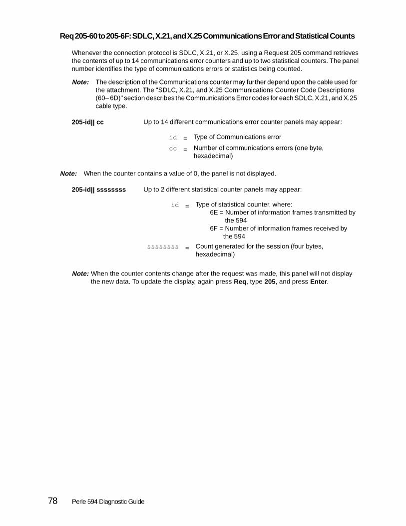
Req 205-60 to 205-6F: SDLC, X.21, and X.25 Communications Error and Statistical Counts
Whenever the connection protocol is SDLC, X.21, or X.25, using a Request 205 command retrievesthe contents of up to 14 communications error counters and up to two statistical counters. The panelnumber identifies the type of communications errors or statistics being counted.
Note: The description of the Communications counter may further depend upon the cable used for the attachment. The "SDLC, X.21, and X.25 Communications Counter Code Descriptions (60– 6D)" section describes the Communications Error codes for each SDLC, X.21, and X.25 cable type.
205-id || cc Up to 14 different communications error counter panels may appear:
Note: When the counter contains a value of 0, the panel is not displayed.
205-id || ssssssss Up to 2 different statistical counter panels may appear:
Note: When the counter contents change after the request was made, this panel will not display the new data. To update the display, again press Req, type 205, and press Enter .
id = Type of Communications error
cc = Number of communications errors (one byte, hexadecimal)
id = Type of statistical counter, where:6E = Number of information frames transmitted by the 5946F = Number of information frames received by the 594
ssssssss = Count generated for the session (four bytes, hexadecimal)
78 Perle 594 Diagnostic Guide

SDLC, X.21, and X.25 Communications Counter Code Descriptions (60– 6D)
The types of errors tracked by the Communications counters depend upon both thecommunications protocol and the cable used for the attachment. This section describes theCommunications Error codes for cable types used with SDLC, X.21, and X.25 protocols.
When the current connection uses SDLC over an EIA 232D (V.24/28) or V.35 cable:
When the current connection uses SDLC over an X.21 cable:
When the current connection uses X.21:
60 = Test Frames in Error
61 = Test Frames without Error
62 = Communication Underrun
63 = Communication Adapter Overrun
64 = Data Carrier Detect (DCD) Signal Lost
65 = Ready For Sending (RFS) Signal Lost
66 = Data Set Ready (DSR) Signal Lost
67 = Frame Sequence Error Counter
68 = Transmit Retry
69 = Frame Check Sequence (FCS) Error Counter
6A = Frame Aborts Counter
6B = (Reserved)
60 = Test Frames in Error
61 = Test Frames without Error
62 = Communication Underrun
63 = Communication Adapter Overrun
64 = Indicate (I) Signal Lost
66 = DCE Is Not Ready
67 = Frame Sequence Error Counter
Chapter 2. Concurrent Diagnostics 79

When the current connection uses X.25 over an EIA (V.24/28) or V.35 cable:
When the current connection uses X.25 over an X.21 cable:
68 = Transmit Retry
69 = Frame Check Sequence (FCS) Error Counter
6A = Frame Aborts Counter
6B = (Reserved)
6C = Short Hold Mode (SHM) Call Collision
6D = IA5 Parity Error.
60 = RNR Sent
61 = RNR Received
62 = Communication Underrun
63 = Communication Adapter Overrun
64 = Data Carrier Detect (DCD) Signal Lost
65 = Ready For Sending (RFS) Signal Lost
66 = Data Set Ready (DSR) Signal Lost
67 = Reject (REJ) Command Sent
68 = Reject (REJ) Command Received
69 = Frame Check Sequence (FCS) Error Counter
6A = Frame Aborts Counter
6B = (Reserved)
6C = T1 Timeout
6D = IPDU Retransmission.
60 = RNR Sent
61 = RNR Received
62 = Communication Underrun
63 = Communication Adapter Overrun
64 = Indicate (I) Signal Lost
66 = DCE Is Not Ready
67 = REJ Command Sent
68 = REJ Command Received
69 = Frame Check Sequence (FCS) Error Counter
6A = Frame Aborts Counter
6B = (Reserved)
6C = T1 Timeout
6D = IPDU Retransmission.
80 Perle 594 Diagnostic Guide

Req 205-01—205-20: AS/400 Token-Ring Communications Error and Statistical Counts
Whenever the connection is Token-Ring, using a Request 205 command retrieves the contents of upto 20 communications error and statistical counters. The panel number identifies the type ofcommunications errors or statistics being counted.
205-id ||occcccccc Panels 205-01 through 205-10 display both the type and number of communications errors generated during the session, where:
205-11||rrrr rrrr through 205-15||rrrr rrrr
Up to five panels of routing data may appear, and each panel may display up to four bytes of data.
205-id ||occcccccc Panels 205-16 through 205-20 display more error and communication statistics, where:
Note: When the counter contents change after the request was made, this panel will not display the new data. To update the display, again press Req, type 205, and press Enter.
id = Counter type, where:01 = Line error count02 = Burst error count03 = Abort Delimiter count04 = Receive Congestion error count05 = Frequency error count06 = Internal error count07 = Access Control error count08 = Lost frame count09 = Frame Copy error count10 = Token error count
o = Overflow Bit
Note: If o=1, the number of errors (cccccccc) displayed is not valid.
cccccccc = Number of Communications Errors generated during the session (4 bytes, hexadecimal).
id = Counter type, where:16 = Transmit error count17 = Receive error count18 = T1 Timer Expired count19 = Transmit frame count20 = Receive frame count
o = Overflow Bit
Note: If o=1, the number of errors (cccccccc) displayed is not valid.
cccccccc = Number of errors or events generated during the session.
Chapter 2. Concurrent Diagnostics 81

Req 205-01 to 205-20: AS/400 Ethernet Communications Error and Statistical Counts
Whenever the connection is Ethernet, using a Request 205 command retrieves the contents of up to20 communications error and statistical counters.
Note: Panels 205-03 through 205-15 are reserved, so the contents are not relevant.
The panel number identifies the type of communications errors or statistics being counted.
205-id ||occcccccc All panels of data appear in the same format, where:
Note: When the counter contents change after the request was made, this panel will not display the new data. To update the display, again press Req, type 205, and press Enter .
id = Counter type, where:01 = Network transmit errors02 = Network receive congestion errors16 = Transmit error count17 = Receive error count18 = T1 Timer Expired count19 = Transmit frame count20 = Receive frame count
o = Overflow Bit
Note: If o=1, the number of errors(cccccccc) displayed is not valid.
cccccccc = Counter contents
82 Perle 594 Diagnostic Guide

Req 205-01 to 205-20: Frame Relay Communications Error and Statistical Counts
205-id || cccccccc All panels of data appear in the same format, where:
id = Counter type, where:01 = LMI timeout count02 = LMI sequence error count03 = LMI protocol error count04 = PM DSR error count05 = PM CTS error count06 = Aborted frame count07 = FCS error count08 = Residue error count09 = Overrun count10 = Underrun count11 = No receive buffers count12 = Misaddressed frame count13 = Frames received in error14 = Filtered frame count15 = Frames received with BECN count16 = Frames received with FECN count17 = Frames received with DE count18 = T1 timer expired count19 = Transmit frame count20 = Receive frame count
cccccccc = Counter contents.
Chapter 2. Concurrent Diagnostics 83
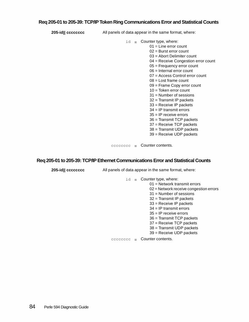
Req 205-01 to 205-39: TCP/IP Token Ring Communications Error and Statistical Counts
205-id || cccccccc All panels of data appear in the same format, where:
Req 205-01 to 205-39: TCP/IP Ethernet Communications Error and Statistical Counts
205-id || cccccccc All panels of data appear in the same format, where:
id = Counter type, where:01 = Line error count02 = Burst error count03 = Abort Delimiter count04 = Receive Congestion error count05 = Frequency error count06 = Internal error count07 = Access Control error count08 = Lost frame count09 = Frame Copy error count10 = Token error count31 = Number of sessions32 = Transmit IP packets33 = Receive IP packets34 = IP transmit errors35 = IP receive errors36 = Transmit TCP packets37 = Receive TCP packets38 = Transmit UDP packets39 = Receive UDP packets
cccccccc = Counter contents.
id = Counter type, where:01 = Network transmit errors02 = Network receive congestion errors31 = Number of sessions32 = Transmit IP packets33 = Receive IP packets34 = IP transmit errors35 = IP receive errors36 = Transmit TCP packets37 = Receive TCP packets38 = Transmit UDP packets39 = Receive UDP packets
cccccccc = Counter contents.
84 Perle 594 Diagnostic Guide

Req 205-01 to 205-39: TCP/IP Frame Relay Communications Error and Statistical Counts
205-id || cccccccc All panels of data appear in the same format, where:
Req 205: TCP/IP Async PPP Communication Error and Statistical Counts
205-id||ccccccccc
id = Counter type, where:01 = LMI timeout count02 = LMI sequence error count03 = LMI protocol error count04 = PM DSR error count05 = PM CTS error count06 = Aborted frame count07 = FCS error count08 = Residue error count09 = Overrun count10 = Underrun count11 = No receive buffers count12 = Misaddressed frame count13 = Frames received in error14 = Filtered frame count15 = Frames received with BECN count16 = Frames received with FECN count17 = Frames received with DE count18 = T1 timer expired count19 = Transmit frame count20 = Receive frame count31 = Number of sessions32 = Transmit IP packets33 = Receive IP packets34 = IP transmit errors35 = IP receive errors36 = Transmit TCP packets37 = Receive TCP packets38 = Transmit UDP packets39 = Receive UDP packets
cccccccc = Counter contents.
id = 01 = bad crc frame count02 = receive frame count03 = transmit frame count04 = overrun count05 = underrun count31 = # of session32 = transmit ip33 = recieve ip34 = ip transmit error35 = ip receive error36 = reansmit TCP37 = recieve TCP38 = transmit UDP39 = recieve UDP
Chapter 2. Concurrent Diagnostics 85

Req 206: Contents of the Communication State Byte
The 594 Communication State byte contains a record of any attempt, at the time of the request, toestablish a logical connection with the AS/400 system. Interpretation of the contents of the 594communication state byte depends on the communication method. The following pages describe how tointerpret the contents of the communication state byte for each AS/400 communication method.
206-c1||abcd efgh Each panel appears in the following basic format, where:
c = Communication method, where:1 = SDLC or X.21 Leased2 = X.253 = X.21 Switched4 = Token-Ring5 = Ethernet6 = Frame Relay7 = Async PPP
1 = Panel identifier
abcd efgh = The contents of the Communication State Byteappears in groups of four bits each.
Note: The description of each bit depends on theselected communication method.
86 Perle 594 Diagnostic Guide

Req 206: AS/400 SDLC or X.21 Leased Communication State Byte
Whenever the 594 is logically connected to the AS/400 system over an SDLC or X.21 Leased link,the Communication State Byte contents appear in the following format:
Note: Reserved values may appear as 0 or 1.
206-11|| abcd efgh Communication State Byte contents, at the time of the request, where:
Note: When there are link status changes after the request was made, the display will not be automatically updated. To update the display, press Req, type 206, and press Enter .
a = Was the received address verified against theconfigured address?
0 = No1 = Yes
b = FSC: Had the 594 received at least one good frame?0 = No1 = Yes
c = XID: Had the 594 received the XID frame?0 = No1 = Yes
d = SNRM: Had the 594 been ready to respond to the AS/400?0 = Set Normal Response Mode (SNRM) was
not entered1 = SNRM was entered
e = Had the 594 ever entered Normal Response Mode (NRM)?0 = No1 = Yes
f = (Reserved)
g = (Reserved)
h = What is the current state of the 594?0 = Normal Disconnect Mode (NDM)1 = Normal Response Mode (NRM)
Chapter 2. Concurrent Diagnostics 87

Req 206: AS/400 X.25 Communication State Byte
Whenever the 594 is logically connected to the AS/400 system over an X.25 link, the CommunicationState Byte contents appear in the following format:
Note: Reserved values may appear as 0 or 1.
206-21|| abcd efgh Communication State Byte contents, at the time of the request, where:
Note: When there are link status changes after the request was made, the display will not be automatically updated. To update the display, press Req, type 206, and press Enter .
a = Was the received address verified against theconfigured address?
0 = No1 = Yes
b = FSC: Had the 594 received at least one good frame?0 = No1 = Yes
c = UA: Had the unnumbered acknowledgment beenreceived from the previously sent SABM signal?
0 = No1 = Yes
d = Had the 594 confirmed that the Packet Level hadrestarted following a Request To Send (RTS)?
0 = No1 = Yes
e = Had transfer of an information frame started at thetime of the request?
0 = No1 = Yes
f = (Reserved)
g = (Reserved)
h = Had transfer of Logical Link Control (LLC) data beenstarted at the time of the request?
0 = No1 = Yes
88 Perle 594 Diagnostic Guide

Req 206: AS/400 X.21 Switched Communication State Byte
Whenever the 594 is logically connected to the AS/400 system over an X.21 Switched link, theCommunication State byte contents appear in the following format:
206-31|| abcd efgh Communication State Byte contents, at the time of the request, where:
Note: When there are link status changes after the request was made, the display will not be automatically updated. To update the display, press Req, type 206, and press Enter .
a = Had the 594 started a call sequence?0 = No1 = Yes
b = Had the 594 entered State 12, SDLC mode?0 = No1 = Yes
c = Was the received address verified against theconfigured address?
0 = No1 = Yes
d = FSC: Had the 594 received at least one good frame?0 = No1 = Yes
e = XID: Had the 594 received the XID frame from the AS/400?0 = No1 = Yes
f = SNRM: Had the 594 been ready to respond to the AS/400?0 = Set Normal Response Mode (SNRM) was not entered1 = SNRM was entered
g = Had the 594 ever entered Normal Response Mode (NRM)?0 = No1 = Yes
h = What is the current state of the 594?0 = Normal Disconnect Mode (NDM)1 = NRM
Chapter 2. Concurrent Diagnostics 89

Req 206: Token-Ring Adapter Status
Whenever the 594 is logically connected to the AS/400 system over a Token-Ring link, theCommunication State byte contents appear in the following format:
Note: Reserved values may appear as 0 or 1.
206-41||abcd efgh Communication State Byte contents, at the time of the request, where:
Note: When there are link status changes after the request was made, scrolling to the top of the list will not display the new data. To update the display, again press Req, type 206, and press Enter .
Req 206: Ethernet Adapter Status
When the 594 is logically connected to the AS/400 system over an Ethernet link, the CommunicationState byte contents appear in the following format:
Note: Reserved values may appear as 0 or 1.
206-51||abcd Communication State Byte contents, at the time of the request, where:
a = (Reserved)
b = (Reserved)
c = (Reserved)
d = (Reserved)
e = (Reserved)
f = (Reserved)
g = Is the Token-Ring adapter open?0 = No1 = Yes
h = Token-Ring speed, where:0 = 4-Mbps1 = 16-Mbps
a = (Reserved)
b = (Reserved)
c = (Reserved)
d = Is the Ethernet adapter open?0 = No1 = Yes
90 Perle 594 Diagnostic Guide

Req 206: Frame Relay Adapter Status
When the 594 is logically connected to the AS/400 system via Frame Relay, the Communication Statebyte contents appear in the following format:
Note: Reserved values may appear as 0 or 1.
206-61||abcd efgh Communication State Byte contents, at the time of the request, where:
Req 206: Async PPP Adapter Status
206-71||abcd efgh
a = (Reserved)
b = (Reserved)
c = (Reserved)
d = (Reserved)
e = (Reserved)
f = (Reserved)
g = (Reserved)
h = Is the adapter open?0 = No1 = Yes
cd = Which Link is established ?00 = no link established01 = link 1 established10 = link 2 established11 = link 3 established
h = Is the adapter open?0 = No1 = Yes
Chapter 2. Concurrent Diagnostics 91

Req 207: Contents Of the 594 SNA State Byte (AS/400 Logical Unit Status)
The 594 Communication SNA byte contains a record of any attempt by the 594 to establish a logicalconnection with the Logical Unit (LU) of the AS/400 system.
Note: Reserved values may appear as 0 or 1.
207|| abcd efgh Regardless of the communication method, information appears in the same format, where:
Note: When there are status changes after the request was made, the display will not be automatically updated. To update the display, press Req, type 207, and press Enter .
a = 1 if the Activate Logical Unit (ACTLU) signal was received
b = (Reserved)
c = 1 if the SNA LU 4 or 7 BIND was complete
d = 1 if accepting workstation data streams
e = 1 if an EC load was in progress
f = 1 if an EC load was flagged
g = 1 if LU 6.2 controller session is active
h = 1 if Primary host download was complete
92 Perle 594 Diagnostic Guide

Req 208-11 to 208-51: Contents of the 594 Communication Interface Register
The 594 Communication Interface Register contains cable type data rather than communications methoddata.
208-xy ||abcd efgh When communication takes place over an EIA 232D (V.24/28), V.35, or X.21 cable, data appears in the following format, where:
208-x1||********* When the cable type is either Token-Ring or Ethernet, contents of the communication interface register are meaningless. The panel appears as shown, where:
x = Cable type, where:1 = EIA 232D (V.24/28) or V.35 cable2 = X.21 cable
y = Panel identifier
abcd efgh = Contents of the 594 communication interfaceregister
x = Cable type, where:4 = Token-Ring5 = Ethernet
Chapter 2. Concurrent Diagnostics 93

Req 208-11 to 208-12: EIA 232D (V.24/28) or V.35 Communication Interface Status
Whenever the Perle 594 communicates with the AS/400 over an EIA 232D (V.24/28) or V.35 cable,using a Request 208 command displays two panels of communication interface status data.
0 indicates that the signal is active; 1 indicates that the signal is inactive.
Note: Reserved values may appear as 0 or 1.
208-11||abcd efgh When the cable type is EIA 232D (V.24/28) or V.35, this panel appears, where:
208-12||abcd efgh The second panel displays more communication interface status data, where:
Note: When there are status changes after the request was made, the display will notbe automatically updated. To update the display, press Req, type 208, and pressEnter .
a = Receive Data (RD)
b = (Reserved)
c = Receive clock (RSET)
d = Transmit clock (TSET)
e = Data Set Ready (DSR)
f = Ready For Sending (RFS)
g = Carrier Detect (CD)
h = Calling Indicator (CI)
a = Transmit Data (TD)
b = Data Terminal Ready (DTR) or Connect Data Set to Line (CDSTL)
c = Request To Send (RTS)
d = Local Loopback
e = (Reserved)
f = (Reserved)
g = (Reserved)
h = (Reserved)
94 Perle 594 Diagnostic Guide

Req 208-21 to 208-22: X.21 Communication Interface Status
Whenever the Perle 594 communicates with the AS/400 over an X.21 communication interface, usinga Request 208 command displays two panels of communication interface status data.
0 indicates that the signal is active; 1 indicates that the signal is inactive.
Note: Reserved values may appear as 0 or 1.
208-21||abcd efgh When the cable type is X.21, this panel appears, where:
208-22||abcd efgh The second panel displays more communication status data, where:
Req 208-41—208-51: Token-Ring/Ethernet Communication Interface
When the Perle 594 communicates with the AS/400 through a Token Ring or Ethernet interface, thereare two panels displayed.
208-41||********* When the communication method is Token-Ring, this panel appears.
208-51||********* When the communication method is Ethernet, this panel appears.
a = Receive Data (RD)
b = (Reserved)
c = Network clock
d = Network clock
e = (Reserved)
f = (Reserved)
g = Indicate (I)
h = 1 if Transmit Wait For Network Ready
a = Transmit Data (TD)
b = (Reserved)
c = Control (C)
d = (Reserved)
e = 1 if Data Communications Equipment (DCE) was NotReady
f = (Reserved)
g = 1 if Wait for Proceed to Select
h = (Reserved)
Chapter 2. Concurrent Diagnostics 95

Req 209-01 to 209-15: Perle 594 LAN Gateway Error Counts
Using a Request 209 command retrieves LAN Gateway error counts.
209-id ||occcccccc When there is a Token-Ring or Ethernet gateway configured, each panel number indicates the error counter type and the panel displays the error counter contents, where:
209||************ This panel appears whenever there is no LAN gateway configured.
Note: When the counter contents change after the request was made, this panel will not display the new data. To update the display, press Req, type 209, and press Enter .
id = Token-Ring counter type, where:01 = Line error count02 = Burst error count03 = Abort Delimiter count04 = Receive Congestion error count05 = Frequency error count06 = Internal error count07 = Access Control error count08 = Lost frame count09 = Frame Copy error count10 = Token error count11 = Transmit error count12 = Receive error count13 = T1 timer expired count14 = Transmit Frame count15 = Receive Frame count
id = Ethernet counter type, where:01 = Network Transmit error count02 = Network Receive Congestion error count11 = Station Transmit error count12 = Station Receive error count13 = T1 timer expired count14 = Transmit Frame count15 = Receive Frame count
Note : When the gateway is Ethernet, Panels 209-03through 209-10 do not appear.
o = Overflow Bit
Note: If o=1, the number of errors (cccccccc)displayed is not valid.
cccccccc = Number of errors
96 Perle 594 Diagnostic Guide

Req 210-00 to 210-36: Status of 594 Twinaxial Devices
Using the Request 210 command retrieves device identification data for each active twinaxial device.
210-xs || wwww mmm Information for each device appears on a separate panel, where:
If the attached twinax device supports IP then the following two panels will appear:
210-p1||<jjj .jjj > Twinax device IP address (first half)
210-p2||< .jjj Twinax device IP address (second half)
Note: If the IP address jjj.jjj.jjj.jjj is ***.***.***.*** then the twinax device has not been assigned an IP address yet.
210||************ This panel appears either
• when you are displaying the end of the list of connected twinaxial devices
or
• when no twinaxial devices were connected at the time of the request
Note: When the status of any device changes after the request was made, this panel will not display the new data. To update the display, again press Req, type 210, and press Enter .
Req 210-x1—210-x6: Status of Emulated ASCII Devices (Perle 594e only)
Using the Request 210 command retrieves both port identification and EIA 232D interface data for eachASCII feature card port that is connected to a device at the time of the request. Panel numbers show theport number and panel identifier.
210-x1|| wwww mmm Device identification data, where:
210-x2|| wwww mmm When the current port has a passthrough ASCII printer connected, this panel appears. It displays printer identification data, where:
xs = Device identifier, where:1st digit = port (0– 7)2nd digit = station (0– 6)
wwww = Device type
mmm = Device model
x = Port number associated with the emulateddevice (0– 7)
wwww = Emulated device type
mmm = Emulated device model
x = ASCII port number (0– 7)
wwww = Emulated printer type
mmm = Emulated printer model
Chapter 2. Concurrent Diagnostics 97

Note: When a passthrough ASCII printer is not connected, this panel does not appear.
210-x3||aa bb ASCII terminal/PC and printer data, where:
210-x4||abcd efgh On this panel, 0 indicates that the signal is active and 1 indicates that the signal is inactive. Reserved values may appear as 0 or 1.
EIA 232D interface status data, where:
x = ASCII port number (0– 7)
aa = ASCII display device type, where:01 = PerleTALK02 = PerleTALK for Windows03 = AS/400 PC Support04 = CrossTalk05 = ProComm06 = DEC VT-10007 = Minitel
bb = ASCII printer type, where:01 = Generic02 = Citoh 4000 series03 = Epson04 = Epson DFX05 = Epson LQ06 = HP DeskJet07 = HP LaserJet II/III08 = HP LaserJet II/III Landscape09 = HP LaserJet 410 = IBM ProPrinter11 = IBM QuietWriter12 = Okidata 29313 = IBM 381214 = PerleTALK for Windows printer
Note: When a passthrough ASCII printer is not connected, this field is blank.
x = ASCII port number (0– 7)
a = Receive Data (RD)
b = (Reserved)
c = (Reserved)
d = (Reserved)
e = Data Set Ready (DSR)
f = (Reserved)
g = Carrier Detect (CD)
h = Calling Indicator (CI)
98 Perle 594 Diagnostic Guide

210-x5||abcd efgh On this panel, 0 indicates that the signal is active and 1 indicates that the signal is inactive. Reserved values may appear as 0 or 1.
Additional EIA 232D interface status data, where:
210-x6||aa bb cc EIA 232D communications parameters, where:
210||************ This panel appears either:
• when you are displaying the end of the list of connected ASCII devices
or
• when no ASCII devices were connected at the time of the request
Note: When the status of any device changes after the request was made, this panel will not display the new data. To update the display, again press Req, type 210, and press Enter .
x = ASCII port number (0– 7)
a = Transmit Data (TD)
b = Data Terminal Ready (DTR)
c = Request To Send (RTS)
d = (Reserved)
e = Clear To Send (CTS)
f = (Reserved)
g = (Reserved)
h = (Reserved)
x = ASCII port number (0– 7)
aa = Baud rate, where:00 = 30001 = 60002 = 120003 = 240004 = 480005 = 960006 = 14.4K07 = 19.2K08 = 38.4K09 = 57.6K10 = 115K
bb = Parity, where:00 = (none)01 = Odd02 = Even
cc = Flow control, where:00 = Hardware01 = Xon/Xoff02 = (none)
Chapter 2. Concurrent Diagnostics 99
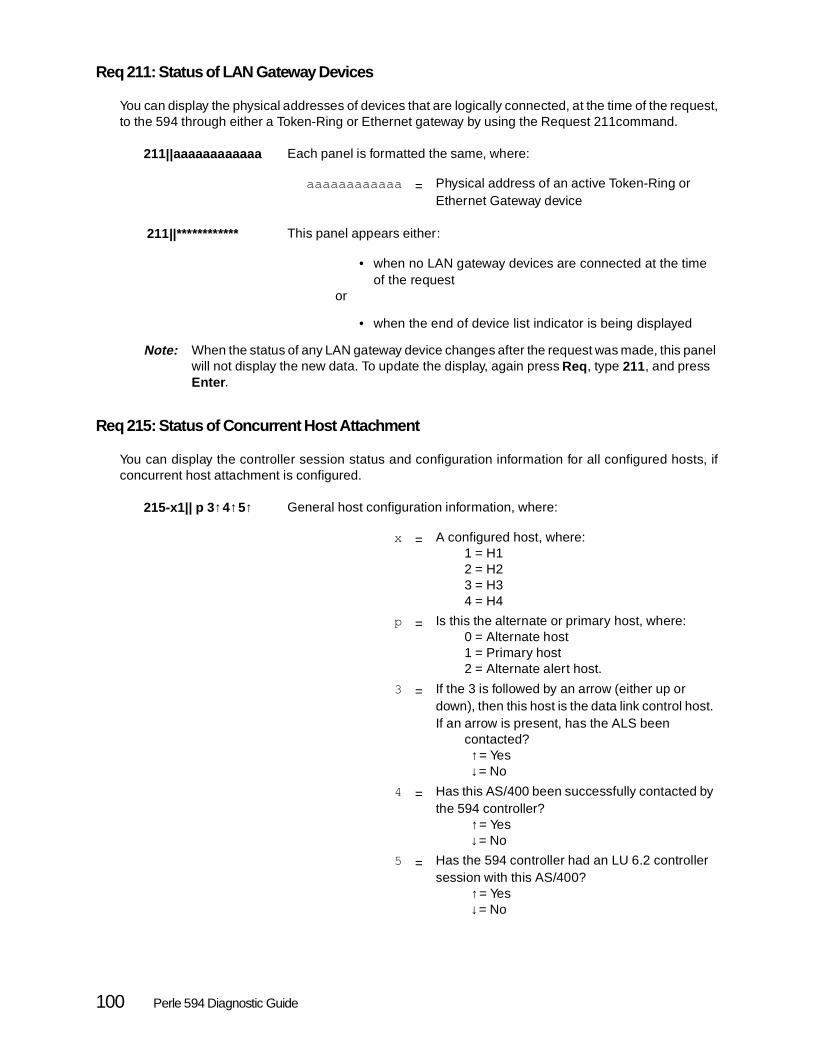
Req 211: Status of LAN Gateway Devices
You can display the physical addresses of devices that are logically connected, at the time of the request,to the 594 through either a Token-Ring or Ethernet gateway by using the Request 211command.
211||aaaaaaaaaaaa Each panel is formatted the same, where:
211||************ This panel appears either:
• when no LAN gateway devices are connected at the time of the request
or
• when the end of device list indicator is being displayed
Note: When the status of any LAN gateway device changes after the request was made, this panel will not display the new data. To update the display, again press Req, type 211, and press Enter .
Req 215: Status of Concurrent Host Attachment
You can display the controller session status and configuration information for all configured hosts, ifconcurrent host attachment is configured.
215-x1|| p 3 ↑4↑5↑ General host configuration information, where:
aaaaaaaaaaaa = Physical address of an active Token-Ring orEthernet Gateway device
x = A configured host, where:1 = H12 = H23 = H34 = H4
p = Is this the alternate or primary host, where:0 = Alternate host1 = Primary host2 = Alternate alert host.
3 = If the 3 is followed by an arrow (either up ordown), then this host is the data link control host.If an arrow is present, has the ALS been
contacted? ↑= Yes ↓= No
4 = Has this AS/400 been successfully contacted bythe 594 controller?
↑= Yes ↓= No
5 = Has the 594 controller had an LU 6.2 controllersession with this AS/400?
↑= Yes ↓= No
100 Perle 594 Diagnostic Guide

215-x2|| nnnnnnnn The LU name of this AS/400, where:
215-x3|| nnnnnnnn The network name of this AS/400, where:
215-x4|| nnnnnnnn The 594 network name for this AS/400, where:
215-x5|| nnnnnnnn The mode name for this AS/400, where:
x = A configured host, where:1 = H12 = H23 = H34 = H4
nnnnnnnn = LU name of this host.
x = A configured host, where:1 = H12 = H23 = H34 = H4
nnnnnnnn = Network name of this host.
x = A configured host, where:1 = H12 = H23 = H34 = H4
nnnnnnnn = 594 network name for this host.
x = A configured host, where:1 = H12 = H23 = H34 = H4
nnnnnnnn = Mode name for this host.
Chapter 2. Concurrent Diagnostics 101

Req 216: Displaying the 594e LAN Adapters Permanent Address
The 594 Token-Ring or Ethernet adapter's permanent (Universal) address can be displayed while the 594is in operation, by doing one of the following procedures.
If in Compatible Mode (Perle 594e only):
Step 1 Press Req and type 216. Press Enter. The permanent address will be displayed on the LCD in the following format:
216||aaaaaaaaaaaa
Where aaaaaaaaaaaa is the LAN adapter's permanent address in token-ring format.
Note: If the display consists of 216||************, it indicates that no LAN adapter card is installed in the 594
If in Enhanced Mode:
Step 2 Press Req and type 216. Press Enter. The following panel will appear on the LCD:
>xx yy<
216-01||
Where:
xx indicates the slot number of the LAN adapter card
yy indicates the card id of the LAN adapter (43 - Token-Ring, 45 - Ethernet, 49 - Fast Ethernet)
Note: If the display consists of 216||************, it indicates that no LAN adapter card in installed in the 594.
Step 3 Use the up and down arrow keys to select the LAN adapter you wish to display the permanent address of.
Step 4 Press Enter. The permanent address of the selected adapter will be displayed on the LCD in the following format:
>xx yy<
216||aaaaaaaaaaaa
Where:
xx indicates the slot number of the LAN adapter cardyy indicates the card id of the LAN adapter (43 - Token-Ring, 45 - Ethernet, 49 - Fast Ethernet)aaaaaaaaaaaa is the LAN adapter's permanent address in token-ring format
102 Perle 594 Diagnostic Guide
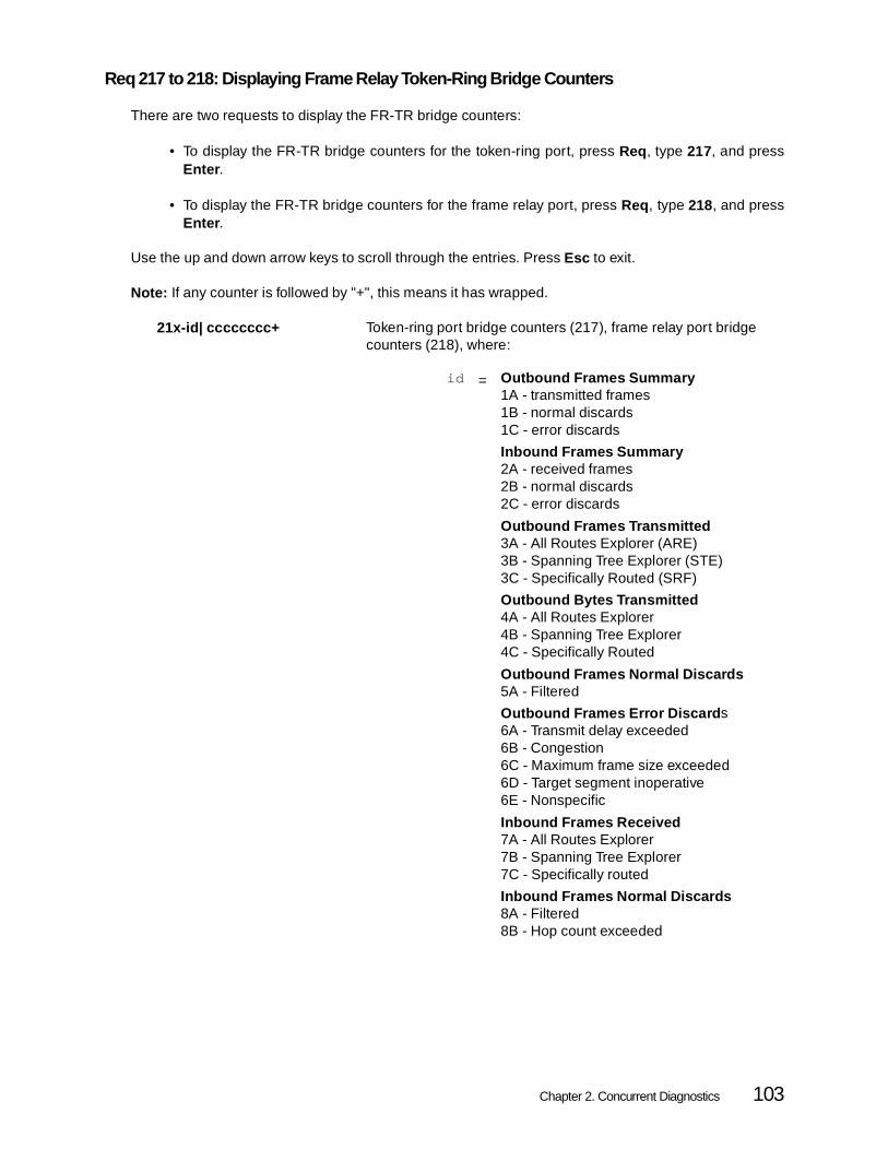
Req 217 to 218: Displaying Frame Relay Token-Ring Bridge Counters
There are two requests to display the FR-TR bridge counters:
• To display the FR-TR bridge counters for the token-ring port, press Req, type 217, and pressEnter .
• To display the FR-TR bridge counters for the frame relay port, press Req, type 218, and pressEnter .
Use the up and down arrow keys to scroll through the entries. Press Esc to exit.
Note: If any counter is followed by "+", this means it has wrapped.
21x-id| cccccccc+ Token-ring port bridge counters (217), frame relay port bridge counters (218), where:
id = Outbound Frames Summary1A - transmitted frames1B - normal discards1C - error discards
Inbound Frames Summary2A - received frames2B - normal discards2C - error discards
Outbound Frames Transmitted3A - All Routes Explorer (ARE)3B - Spanning Tree Explorer (STE)3C - Specifically Routed (SRF)
Outbound Bytes Transmitted4A - All Routes Explorer4B - Spanning Tree Explorer4C - Specifically Routed
Outbound Frames Normal Discards5A - Filtered
Outbound Frames Error Discard s6A - Transmit delay exceeded6B - Congestion6C - Maximum frame size exceeded6D - Target segment inoperative6E - Nonspecific
Inbound Frames Received7A - All Routes Explorer7B - Spanning Tree Explorer7C - Specifically routed
Inbound Frames Normal Discards8A - Filtered8B - Hop count exceeded
Chapter 2. Concurrent Diagnostics 103

Req 219 to 220: Reset Bridge Counters
There are two requests to reset the FR-TR bridge counters to zero. To reset the FR-TR bridge countersfor the token-ring port, press REQ, type 219, and press Enter .
To reset the FR-TR bridge counters for the frame relay port, press REQ, type 220, and press Enter .
The operator panel displays a blank panel or any current error messages once the operation is complete.
Req 240: Start/Stop FR-TR Bridge Frame Forwarding
This request can be used to start and stop FR-TR Bridge frame forwarding by doing the followingprocedure:
Step 1 Press Req and type 240. Press Enter.
The following panel will appear on the LCD:
240-01|| aa
Note: If the display consists of 240||************, it indicates that the FR-TR bridge is not configured.
Step 2 Use the up and down arrow keys to select start or stop forwarding frames.
Step 3 Press Enter to perform the selected operation.
The operator panel displays a blank panel or any current error messages once the operation is complete.
Inbound Frames Error Discards9A - Congestion9B - Invalid route information9C - SRF duplicate segment9D - STE duplicate segment9E - STE or ARE mismatch9F - Nonspecific
cccccccc Counter
+ Overflow indicator (blank if no overflow)
217|************ 217 or 218 = Request code entered by user
218|************ ************ = FR-TR Bridge is not configured
where aa = 00 - do not change frame forwarding status (default value)01 - start frame forwarding02 - stop frame forwarding
104 Perle 594 Diagnostic Guide

Req 241: Start/Stop IP Router Frame Forwarding
This request can be used to start and stop IP Router frame forwarding by doing the following procedure:
Step 1 Press Req and type 240. Press Enter.
The following panel will appear on the LCD:
241-01|| aa
Note: If the display consists of 241||************, it indicates that the IP Router is not configured.
Req 250: Display 594 IP Router Configuration Inforamtion
If the 594 has been configured with IP Routing then this request is used to display general IP Routerconfiguration information
250-01|| jjj.jjj.* IP Router Default Gateway IP address (first half)
250-02|| *jjj.jjj IP Router Default Gateway IP address (last half) Note: for 0.0.0.0 means go out on this port
250-03||a IP Router frame forwarding status, where:
250-04||b Frame Relay Dynamically Discovered DLCIs enabled, where:
250-05||c RIP Enabled
250||************ IP Router not configured
Req 251: Displaying IP Router Counters
If the 594 has been configured with IP Routing then this request is used to display general IP Routercounters
251-id| cccccccc General IP Router counters, where:
where aa = 00 - do not change frame forwarding status (default value)
01 - start frame forwarding02 - stop frame forwarding
a = 00 = Frame forwarding stopped01 = Frame forwarding started
b = 00 = Dynamically discovered DLCIs disabled01 = Dynamically discovered DLCIs enabled
c = 00 = Disabled01 = Enabled
id = 01 - Packets forwarded
02 - IP discard
Chapter 2. Concurrent Diagnostics 105

251|************ IP Router not configured
Req 252: Reset IP Router Counters
This request resets the general IP Router counters to zero. To reset the IP Router counters, press REQ,type 252, and press Enter .
The operator panel displays a blank panel or any current error messages once the operation is complete.
252||************* IP Router not configured
Req 253: Displaying IP Router Port Information
If the 594 has been configured with IP Routing then this request is used to display one of IP Router portsconfiguration information.
To display a particular IP Router ports information, do the following steps
Step 1 Press Req, type 253, and press Enter . The following panel will appear on the LCD:
>xx yy<
253-01||
Where:
xx indicates the slot number of the IP Router Portyy indicates the card id used for that IP Router Port, where:
96 = Synchronous Feature Card43 = Token-Ring Feature Card45 = Ethernet Feature Card49 = Fast Ethernet Feature Card41 = Twinax Feature Card44 = Twinax Feature Card48 = Twinax Feature Card
Step 2 Use the up and down arrow keys to select a IP Router port and then press Enter . The following panels will appear on the bottom line of the LCD:
253-02||a IP Router port type, where:
253-03||b IP Router port number
253-04|| jjj.jjj.* IP Router port IP address (first half)
03 - IP discards due to no routes were found
cccccccc Counter
a = 01 = Frame Relay port or Async PPP port02 = Token-Ring port03 = Ethernet port04 = Twinax Port
106 Perle 594 Diagnostic Guide

253-05|| *jjj.jjj IP Router port IP address (last half)
253-06||kkk.kkk.* IP Router port IP mask (first half)
253-07|| *kkk.kkk IP Router port IP mask (last half)
253-08||ffff Ethernet frame format (for Ethernet port type only) where:
253||************ IP Router not configured
Step 3 Use the up and down arrow keys to scroll through these entries. Press Esc to exit or press Slot to select a different IP Router port
Req 254: Displaying IP Router Port Counters
If the 594 has been configured with IP Routing then this request is used to display one of IP Router portscounters
To display a particular IP Router ports counters, do the following steps
Step 1 Press Req, type 254, and press Enter . The following panel will appear on the LCD:
>xx yy<
254-01||
Where:
xx indicates the slot number of the IP Router Portyy indicates the card id used for that IP Router Port, where:
96 = Synchronous Feature Card43 = Token-Ring Feature Card45 = Ethernet Feature Card49 = Fast Ethernet Feature Card41 = Twinax Feature Card44 = Twinax Feature Card48 = Twinax Feature Card
Step 2 Use the up and down arrow keys to select a IP Router port and then press Enter . The following panels will appear on the bottom line of the LCD:
254-id|| cccccccc IP Router Port counters, where:
fff = SNAP = SNAP frame typeV2 = Ethernet Type 2 frame type
id = 02 - IP packet discards due to congestion
03 - IP packets received
04 - ICMP packets received
05 - IP packets received on disabled port
06 - IP Packets forwarded
07 - ICMP packets forwarded
Chapter 2. Concurrent Diagnostics 107

253||************ IP Router not configured
Step 3 Use the up and down arrow keys to scroll through these entries. Press Esc to exit or press Slot to select a different IP Router port
Req 255: Reset IP Router Port Counters
This request resets a specific IP Router ports counters to zero. To reset a IP Router ports counters dothe following steps:
Step 1 Press REQ, type 255, and press Enter . The following panel will be displayed on the LCD:
>xx yy<
255-01||
Where:
xx indicates the slot number of the IP Router Portyy indicates the card id used for that IP Router Port, where:
96 = Synchronous Feature Card43 = Token-Ring Feature Card45 = Ethernet Feature Card49 = Fast Ethernet Feature Card41 = Twinax Feature Card44 = Twinax Feature Card48 = Twinax Feature Card
Step 2 Use the up and down arrow keys to select a IP Router port and then press Enter . The operator panel displays a blank panel or any current error messages once the operation is complete.
255||************ No IP Router configured
08 - UDP packets forwarded
09 - TCP packets forwarded
10 - Unrecognized packets forwarded
11 - IP packets not forwarded
12 - IP packets transmitted
cccccccc Counter
108 Perle 594 Diagnostic Guide

Req 256: Display IP Router Static Route Table
If the 594 has been configured with IP Routing or has been configured with any TCP/IP controllers, thenthis request can be used to view your configured IP Router static route entries.
• Use the Up arrow key to display the first panel of the next IP Router static route entry. When you arealready at the top of the list, pressing the Up arrow key displays the End of List indicator.
• Use the Down arrow key to display the first panel of the next IP Router static route entry. When youare displaying the End of List indicator, pressing the Down arrow key displays the first panel of thefirst entry.
• Use the Right arrow key to display the next panel of information for an IP Router static route entry.When you are displaying the last panel of information for an static route entry, no Right arrow keyappears on the panel.
• Use the Left arrow key to display the previous panel of information for an IP Router static route entry.When you are displaying the first panel for a static route entry, no Left arrow key appears on the panel.
Because the list of configured static route entries is displayed in a continuous loop, you can always usethe Up and Down Arrow keys.
256-xx|| jjj.jjj> Destination IP address (first half)
Note : xx = The static route entry number
256-P2||<jjj.jjj> Destination IP address (last half)
256-P3||<kkk.kkk> Destination IP mask (first half)
256-P4||<kkk.kkk> Destination IP mask (last half)
256-P5||<lll.lll> Next hop IP address (first half)
256-P6||<lll.lll Next hop IP address (last half)
256||************ The last static route entry panel in the series indicates the end of the list. If no static entries are configured then this will be the only panel displayed.
Note: P5,P6 0.0.0.0 means go out to Async PPP port
Chapter 2. Concurrent Diagnostics 109
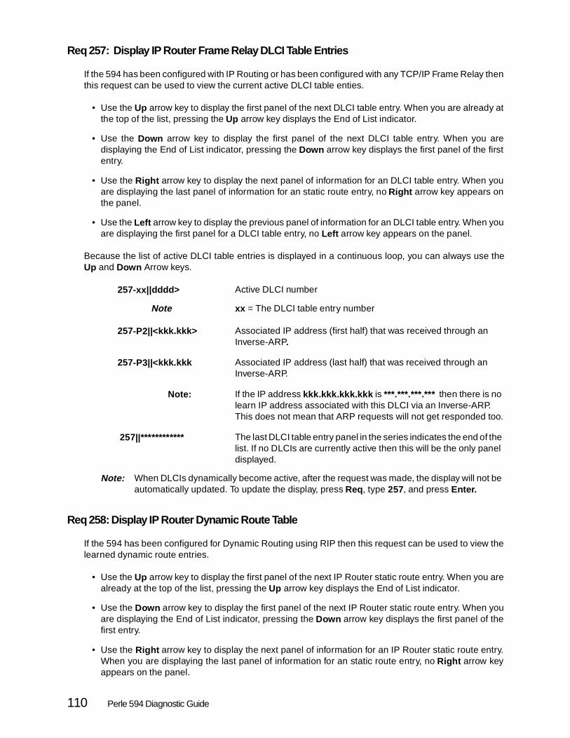
Req 257: Display IP Router Frame Relay DLCI Table Entries
If the 594 has been configured with IP Routing or has been configured with any TCP/IP Frame Relay thenthis request can be used to view the current active DLCI table enties.
• Use the Up arrow key to display the first panel of the next DLCI table entry. When you are already atthe top of the list, pressing the Up arrow key displays the End of List indicator.
• Use the Down arrow key to display the first panel of the next DLCI table entry. When you aredisplaying the End of List indicator, pressing the Down arrow key displays the first panel of the firstentry.
• Use the Right arrow key to display the next panel of information for an DLCI table entry. When youare displaying the last panel of information for an static route entry, no Right arrow key appears onthe panel.
• Use the Left arrow key to display the previous panel of information for an DLCI table entry. When youare displaying the first panel for a DLCI table entry, no Left arrow key appears on the panel.
Because the list of active DLCI table entries is displayed in a continuous loop, you can always use theUp and Down Arrow keys.
257-xx| |dddd> Active DLCI number
Note xx = The DLCI table entry number
257-P2||<kkk.kkk> Associated IP address (first half) that was received through an Inverse-ARP.
257-P3||<kkk.kkk Associated IP address (last half) that was received through an Inverse-ARP.
Note: If the IP address kkk.kkk.kkk.kkk is ***.***.***.*** then there is no learn IP address associated with this DLCI via an Inverse-ARP. This does not mean that ARP requests will not get responded too.
257||************ The last DLCI table entry panel in the series indicates the end of the list. If no DLCIs are currently active then this will be the only panel displayed.
Note: When DLCIs dynamically become active, after the request was made, the display will not be automatically updated. To update the display, press Req, type 257, and press Enter.
Req 258: Display IP Router Dynamic Route Table
If the 594 has been configured for Dynamic Routing using RIP then this request can be used to view thelearned dynamic route entries.
• Use the Up arrow key to display the first panel of the next IP Router static route entry. When you arealready at the top of the list, pressing the Up arrow key displays the End of List indicator.
• Use the Down arrow key to display the first panel of the next IP Router static route entry. When youare displaying the End of List indicator, pressing the Down arrow key displays the first panel of thefirst entry.
• Use the Right arrow key to display the next panel of information for an IP Router static route entry.When you are displaying the last panel of information for an static route entry, no Right arrow keyappears on the panel.
110 Perle 594 Diagnostic Guide

• Use the Left arrow key to display the previous panel of information for an IP Router static route entry.When you are displaying the first panel for a static route entry, no Left arrow key appears on the panel.
Because the list of configured static route entries is displayed in a continuous loop, you can always usethe Up and Down Arrow keys.
258-xx|| jjj.jjj> Destination IP address (first half)
258-P2||<jjj.jjj> Destination IP address (last half)
258-P3||<kkk.kkk> Destination IP mask (first half)
258-P4||<kkk.kkk> Destination IP mask (last half)
258-P5||<lll.lll> Next hop IP address (first half)
258-P6||<lll.lll> Next hop IP address (last half)
258-P7||<m cost metric
258||********** The last static route entry panel in the series indicates the end of the list. If no static entries are configured then this will be the only panel displayed.
Note: P5,P6 0.0.0.0 means go out to Async PPP port
Chapter 2. Concurrent Diagnostics 111

112 Perle 594 Diagnostic Guide

Chapter 3. Extended Diagnostics
Extended diagnostics are used for Perle 594 hardware diagnostics and hardware setup. Unlikeconcurrent diagnostics, extended diagnostics can be used only when the 594 is off-line. This applies tothe 594 (whether it is configured for compatible or enhanced operation). There are 2 different modes ofoperation for Extended Diagnostics:
• Extended Diagnostics - allows you to view Perle 594 features, test all the hardware, set the date and time, and run setup.
• Service Mode - gives you the Extended Diagnostics options with the added options of test-ing selected hardware and viewing the Perle 594 time stamped error log.
The following is a flow chart that illustrates the structure of the Extended Diagnostics and the ServiceMode's main menus and options.
Main Menu1. View 594 features2. Test all 594 hardware3. Set date and time4. Run Setup
Alt+PF1Service Mode
Service Mode Main Menu (030-01)1. View 594 features2. Test all 594 hardware3. Set date and time4. Run setup5. Test selected 594 hardware6. View 594 time stamped error log
Test Selection Menu (030-02)1. Motherboard2. Memory3. Disk drive4. Operator front panel5. Twinaxial card6. Token-ring card7. Etherntet Card8. ASCII card9. Sync card
Test Option Menu (030-03)1. Run one time2. Loop until error3. Loop until Req is pressed
Chapter 3. Extended Diagnostics 113

Running Extended Diagnostics
Step 1 Turn the 594 power off.
Step 2 Remove any diskette from the disk drive.
Step 3 Turn the 594 power on and wait approximately 1 minute while the POST is running. Once themessage code 003-02 is displayed, proceed to step 4. If any other message code is displayed,look it up in chapter 6 to determine the next action.
Step 4 When the message code 003-02 is displayed, insert the 594 Controller Setup Diskette, type 0,and press Enter on the front panel keypad.
Step 5 The main menu (020-01) is displayed with the following functions available:
1. View Perle 594 features (see page 115)
2. Test all Perle 594 hardware (see page 115)
3. Verify or set the date and time (see page 118)
4. Run setup (see page 119).
You can also access the Service Mode main menu by pressing Alt + PF1 . Options 1-4 are similar in Service Mode and there are 2 extra options:
5. Test selected Perle 594 hardware (see page 120)
6. View the Perle 594 time stamped error log (see page 121).
Step 6 Press Esc to exit Extended Diagnostics and restart the Perle 594.
The Extended Diagnostics Main Menu (020-01)
To enter the Extended Diagnostics main menu, follow the procedure under "Power-On Options" on page 5 or"Running Extended Diagnostics" on page 114.
To reboot the Perle 594, press Esc while in the main menu. This will display the message code 020-02 whichasks for confirmation to reboot. Press Enter to restart the 594 or press Esc to return to the main menu.
The following sections describe each option in the Extended Diagnostics main menu and the Service Modemain menu. The Service Mode has 2 additional options that are described on page 119.
114 Perle 594 Diagnostic Guide

View Perle 594 Features
To view Perle 594 features, press 1 and Enter from the main menu (020-01).
All cards have a numeric ID. Message codes will appear on the LCD indicating the type of card installedin each slot. Slot codes are from 021-01 to 021-07. Use the Up and Down arrow keys to scroll throughthe slot definitions. 021-08 indicates the amount of RAM available. See chapter 6 to determine themeaning of other message codes.
Note: In Service Mode, an extra option (021-09) is added to show the type of 594 motherboard."Rev 1.0" means 386 processor motherboard and "Rev 2.0" means 486 processor motherboard.
The following table lists each card type with its corresponding ID number.
Press Esc to return to the main menu.
Test all Perle 594 hardware
To run tests on all hardware, press 2 and Enter from the main menu (020-01).
Message codes will be displayed as the tests run. If manual intervention is required, such as changingthe diskette from the disk drive, a message code will be displayed to indicate that the action is required.Refer to chapter 6 to determine the meaning of all message codes and chapter 7 for the SRC codes. Allcards will be tested for the 594e (compatible or enhanced mode).
Message code 022-04 (030-04 in Service Mode) will be displayed if no problem is found or Req has beenpressed. Press Esc to return to the main menu. If the hardware did not pass all the tests, message code022-05 (030-05 in Service Mode) will be displayed. View the error log as described on page 121.
Card Type ID
Synchronous Communications Card (594e) 96
Synchronous Communications Card (594T) 97
Twinaxial Feature Card (594e) 41
ASCII Feature Card (594e) 42
Token-Ring Feature Card 43
Double Byte Character Set Twinaxial Feature Card(594e)
44
Ethernet Feature Card 45
Twinaxial Feature Card 48
Fast Ethernet Feature Card 49
Chapter 3. Extended Diagnostics 115

Sync Card Loop-Back Diagnostic Test
The Sync card loop-back diagnostic test is used to isolate synchronous communications problems. If the testpasses successfully, then the Sync card is functioning properly. Refer to chapter 6 for message codes andchapter 7 for SRC codes.
Note : A Sync loop-back header is included with the product.
To perform the test, do the following:
Step 1 Disconnect the communication cable from the Synchronous Communication card.
Step 2 Connect the loop-back header to the Synchronous Communication card.
Step 3 Once the Sync card test is running, the message code 039-04 will be displayed prompting youto indicate whether or not the Sync card loop-back header is installed. If it has not yet beeninstalled, it can be installed at this time. Press 1 followed by Enter to start the test. If no loop-backheader is detected, message code 039-03 will be displayed indicating that no loop-back headeris installed.
Note : If message code 039-02 is displayed, then a hardware problem was detected on theSync card. Use the SRC displayed on the front panel LCD to identify the problem andrefer to chapter 7. For any other message codes that appear, look up the message codein chapter 6.
11
5 V
11
5 V
116 Perle 594 Diagnostic Guide

Token-Ring Loop-Back Diagnostic Test
The Token-Ring loop-back diagnostic test is used to isolate problems in the Token-Ring card. If the testpasses successfully, then the Token-Ring card is functioning properly. Refer to chapter 6 for the meaningof message codes and chapter 7 for SRC codes.
Note : RJ45 and DB9 loop-back headers for the Token-Ring card are available from third party dealers.
To perform the test, do the following:
For the IBM Cabling System Token-Ring cable:
Step 1 When the message code 036-03 is displayed, disconnect the IBM Cabling SystemToken-Ring cable from the network, but leave the cable end connected to the Token-Ringcard. Press Enter to continue.
Step 2 Once the test is complete and message code 036-10 is displayed, reconnect the Token-Ringcard to the network and press Enter.
For the Type 3 Media Filter cable or the RJ-45 cable:
Step 1 When message code 036-04 is displayed, disconnect the Type 3 Media Filter cable or theRJ-45 cable from the Token-Ring card and replace it with the loop-back header.
Step 2 Once the test is complete and message code 036-06 is displayed, remove the loop-backheader and reconnect the cable to the Token-Ring card and to the network.
Note : If message code 036-09 is displayed, then a hardware problem was detected on the Token-Ring card. Use the SRC displayed on the front panel LCD to identify the problem and refer to chapter 7. For any other message codes that appear, look up the message code in chapter 6.
Ethernet Loop-Back Diagnostic Test
The Ethernet loop-back diagnostic test is used to isolate problems in the Ethernet card. If the test passessuccessfully, then the Ethernet card is functioning properly. Refer to chapter 6 for message codes andchapter 7 for SRC codes.
Note: Loop-back headers for the Ethernet card are available from third-party dealers.
To perform the test, do the following:
Step 1 When message code 037-02 is displayed, disconnect the communication cable from theEthernet card and replace it with the loop-back header. Press Enter to continue.
Step 2 Once the test is complete and either message code 037-04 or 037-06 is displayed, removethe loop-back header from the Ethernet card and reconnect the cable.
Note : If message code 037-07 is displayed, then a hardware problem was detected on theEthernet card. Use the SRC displayed on the front panel LCD to identify the problemand refer to chapter 7. For any other message codes that appear, look up themessage code in chapter 6.
Chapter 3. Extended Diagnostics 117

ASCII Loop-Back Diagnostic Test (Perle 594e only)
The ASCII loop-back diagnostic test is used to isolate problems in the ASCII card. If the test passessuccessfully, then the ASCII card is functioning properly.
Note: If you want to run the ASCII loop-back test and the DB62 loop-back header is not included with the product, contact your Perle service representative.
To perform the test, do the following:
Step 1 When the message code 038-02 is displayed, disconnect the ASCII cable from the card andreplace it with the DB62 loop-back header. Press Enter to continue.
Note : If message code 038-04 is displayed, then a hardware problem was detected on theASCII card. Use the SRC displayed on the front panel LCD to identify the problem andrefer to chapter 7. For any other message codes that appear, look up the message codein chapter 6.
Set Date and Time
To view and set the date and time, press 3 and Enter from the main menu (020-01).
Setting the Date
When the message code 023-01 is displayed, you can change the date. Valid date ranges are in the order ofYear - Month - Day.
Step 1 Use the arrow keys to move the cursor over the numbers that you want to change.
Step 2 Press any numbers to enter the new values.
Step 3 Press Enter to save the new values, or press Esc to exit without saving.
Valid Date Ranges:
• Year:
91-99 for the years 1991-1999
00-50 for the years 2000-2050
• Month: 01-12
• Day:
01-31 for months with 31 days
01-30 for months with 30 days
01-29 for February (29 is valid for leap year only)
118 Perle 594 Diagnostic Guide

Setting the Time
When the message code 023-02 is displayed, you can change the current time. Valid time ranges are inthe order of Hours - Minutes - Seconds.
Step 1 Use the arrow keys to move the cursor over the numbers that you want to change.
Step 2 Press any numbers to enter the new values.
Step 3 Press Enter to save the new values, or press Esc to exit without saving.
Valid Time Ranges:
• Hour: 00-23
• Minutes: 00-59
• Seconds: 00-59
Run Setup
To run setup, press 4 and Enter from the main menu (020-01).
Note : The 594e in compatible mode, the only option available in run setup is changing the Token-Ring speed.
In Run Setup, you have the option of viewing and changing the card IDs for each slot. Upon entering RunSetup, slot "01" is displayed on the right hand side of the LCD. To move to the next slot, press Enter . Theslot ID can be changed with the up and down arrow keys. See page 115 for card types and their IDs.Once Enter has been pressed for slot "07", asterisks will be displayed. Press Enter again to confirm yoursettings.
Note : The Sync card in slot "01" is the only card ID that cannot be changed.
Once Enter has been pressed for any Token-Ring slot, you have the option of selecting either 4MBPs or16MBPs. Use the up and down arrow keys to select and press Enter to continue.
The Service Mode Main Menu (030-01)
From the Extended Diagnostics main menu, enter the Service Mode main menu by pressing Alt + PF1 .This will bring up message code 030-01. Options 1-4 in the Service Mode are similar to options 1-4 inExtended Diagnostics mode. For a description of these options, see the previous sections.
The following sections are an explanation of the extra 2 options available in Service Mode:
• Test selected Perle 594 hardware
• View 594 time stamped error log
Chapter 3. Extended Diagnostics 119

Test Selected Perle 594 Hardware
The "Test All Perle 594 Hardware" in Extended Diagnostics mode allows you to test all the existing hardwarein the Perle 594. The "Test Selected Perle 594 Hardware" that is part of the Service Mode and is describedhere allows you the opportunity of running tests only on the hardware that you choose.
To access "Test Selected Perle 594 Hardware", make sure you are in the Service Mode main menu (030-01),press 5 and Enter .
This displays the Test Selection Menu with the message code 030-02 on the left side of the LCD. The numbers1 2 3 4 5 6 7 8 9 are displayed on the right-hand side of the LCD. If a number is blank, then there is no hardwareof that type in the system. If you do not want to test a particular piece of hardware, press the correspondingnumber (see table below). This will display a dash (-) which means that this particular test will not be run. Pressany number to toggle the corresponding hardware test ON or OFF.
e.g. If the following is displayed: 1 2 - 4 - - 7 9, it means that you have chosen the motherboard, memory, theoperator front panel, the Ethernet card, and the Sync card to be tested. Note that there is no number 8 ordash for 8, which means that there is no ASCII card in the system to be tested.
The hardware and its corresponding test number are listed in the following table:
Once the test numbers you want are displayed, press Enter to go to the "Test Option Menu". This menudisplays further testing options which are described in the following table.
Press the number or use the arrow keys to select the test option you want. Press Enter to start the tests thatyou have chosen. Message codes will be displayed as the tests run. If manual intervention is required, suchas changing the diskette in the disk drive, a message code will be displayed to indicate that the action isrequired. Refer to chapter 6 to determine the meaning of message codes and chapter 7 for the SRC codes.
Test Enter
Motherboard 1
Memory 2
Disk Drive 3
Operator Front Panel 4
Twinaxial card 5
Token-Ring card 6
Ethernet card 7
ASCII card (594e) 8
Sync card 9
Test Press Result
Run one time 1 runs all selected tests once or until the Req key is pressed.
Loop until error 2 runs all selected tests until an error occurs or until Req key ispressed.
Loop until Req 3 runs all selected tests until the Req key is pressed.
120 Perle 594 Diagnostic Guide

Viewing the Perle 594 Time Stamped Error Log
To access the information stored in the 594 time stamped error log, press 6 and Enter from the ServiceMode main menu (030-01). When the message code 050-01 is displayed, press Enter again.
The message codes 051-xx indicate the fields of information displayed on the 594 LCD. The following isa list of each option and what it displays:
Use the left and right arrow keys to move between fields (051-01 to 051-04). Press Alt + 4 to allowviewing of the optional status byte information field (051-05). The following table describes the format ofeach field.
The LCD initially shows the message code 051-04 and the SRC for the most recent entry in the Perle594 error log (cccccc(s) in the example above).
Optional status bytes include #n which is the sense data byte number and xx which is the sense databyte value in hex.
Use the up and down arrow keys to move between the entries in the log. A beep is sounded when thelimits of the error log have been reached. See chapter 6 for a description of each message code andchapter 7 for the SRCs. Press Esc to return to the main menu.
Note : Any 3 digit hardware SRCs will be displayed as E00xxx .
Further options:
Message Displays
051-01 The error count
051-02 The date
051-03 The time
051-04 The SRC
051-05 Op t ion a l s t a tu s by teinformation
Entry Number
Date Time SRC (Slot) Optional Status Bytes
4/4 dd mmm hh:mm:ss cccccc(s) #n xx
3/4 dd mmm hh:mm:ss cccccc(s) #n xx
2/4 dd mmm hh:mm:ss cccccc(s) #n xx
1/4 dd mmm hh:mm:ss cccccc(s) #n xx
PF1 Momentarily displays the count field for the entry currently displayed. Whenever thesame error consecutively occurs, a count of the error is recorded instead of a new errorlog entry being created for each instance. The date and time of the error log entry is thatof the last occurrence.
PF2 Displays the date field of the first entry for the current date. If the first entry for the currentdate is already being displayed, the first entry for the previous date will be displayed.
Alt + 4 Enables the display of additional status bytes (051-05) associated with each error logentry.
Chapter 3. Extended Diagnostics 121

System Reset
A system reset can be done from almost anywhere in Extended Diagnostics. To perform a system reset tothe various modes, follow the steps below:
• Extended Diagnostics: Press Alt + 0 three times and then Enter . You will be prompted to remove the diskette. The Perle 594 will reboot into Extended Diagnostics mode.
• Normal Mode: Press Alt + 1 three times and then Enter . You will be prompted to insert the Perle 594 Software Diskette. The Perle 594 will reboot into Normal mode.
• Configuration Mode: Press Alt + 2 three times and then Enter . You will be prompted to remove the diskette. The Perle 594 will reboot into Configuration mode.
Note : Another way of rebooting into any of the Perle 594 modes is to remove any diskette from the disk drive and press Alt + 3 three times. You will then be prompted to enter the mode you wish the 594 to reboot into. The following table shows which key to press for the different modes.
For an explanation of all message codes, refer to chapter 6.
During any of the reboot options, pressing Esc will abort the rebooting process and return you to the previousmenu.
Mode Press
Extended Diagnostics 1
Normal 2
Configuration 3
122 Perle 594 Diagnostic Guide

Chapter 4. Use and Creation of Bridge Filter File
This section describes the importance of using bridge filters, how they work and how to create and savethem. It also shows a few examples of some bridge filter files. If you are not using a Frame RelayToken-Ring Bridge configuration then you do not need to read this section.
The Importance of Filtering
Although it is not essential to create a bridge filter, the token-ring speeds are much faster than the framerelay speeds supported on the 594, and a high volume of LAN traffic trying to cross the FR-TR bridgecan cause some undesirable results, such as overflowing buffers, time-outs and lost connections. Inaddition, depending on how you are billed for your frame relay traffic, unnecessary traffic can cost youmoney. Similarly, you might want to insulate your LANs from the frame relay traffic coming across theFR-TR bridge.
The 594 bridge filter will allow you to limit traffic in either or both directions. You can specify precisely thekinds of frames that can cross the FR-TR bridge, by using such attributes as frame type, hop count,source and destination addresses and data within the frames themselves. You can create a bridge filterthat will include those frames you want to cross, exempting those frames you do not want to cross or somecombination of both.
Not everyone needs to filter. If your Frame Relay connection is capable of high speeds (greater than64Kbps) then you might forgo the filtering until you detect a real need for it. The need for filtering is usuallyindicated by network congestion and poor response times. However, even low volume, low speedsystems operate more efficiently with bridge filters.
Filter File Overview
The filter file you created is stored in a file called 594FILT.DAT on the 594 system diskette. You can createthe file yourself or you can modify the 594UP\594FILT.DAT file that comes on the 594 Utility diskette andis installed when you install the 594 Utility program. For more information refer to Editing and Saving 594Filter File on page 133.
The basic unit of the bridge filter is the criterion , in which you specify some attribute of a frame that makesit worthy of crossing or not crossing the bridge. Logically combining two or more criteria yields the nextlarger unit, called a criteria list . The final unit, the filter itself, names the criteria or criteria list that willbe used for filtering. The Boolean logic used to combine criteria and criteria lists allows cumulative, yetvery selective filtering.
When you specify a filtering criterion, you will state whether you are seeking a match (True) or mismatch(False), and when you combine criteria into criteria lists, you'll be using the logical operations AND, OR,NAND, and NOR. Finally, when you use the criteria lists in your bridge filter, the relevant parts of theframes that are trying to cross the bridge will be logically compared to the criteria you have set, and thosethat meet your criteria will be filtered (discarded), and all others will be forwarded.
Chapter 4. Use and Creation of Bridge Filter File 123

Criterion
Criterion Syntax
The parts of a criterion are:
• A name, enclosed in square brackets, like this: [NoARE]. A criterion name is eventually used as an element of one or more criteria lists or possibly as an element in the filter itself. The name can be in upper or lower case and should not exceed 16 characters.
• Optionally, a comment describing the criterion on one or more lines, each beginning with a semicolon character ";". It is recommended that the filter file be well commented so that it is easily understood what the filter file is going to filter.
• One or more criterion keywords in uppercase or lowercase letters. Refer to Bridge Filter Criterion Keywords on page 128 for a list of these keywords.
• One of two possible logical operators:
"=" meaning "equal to"
"!=" meaning "not equal to"
• A filter value, sometimes enclosed in double quotation marks.
Here's a sample criterion:
[NoARE]
;
; Filter any All Routes Explorer frames
;
SourceRouteType = ARE
124 Perle 594 Diagnostic Guide

Bridge Filter Criterion Keywords
The following table shows the valid criterion keywords and the values that you can specify.
Keyword and Description Range Default
SourceRouteTypeSpecifies one of three source-route frame types:
STE, ARE, or SRF None
STE - A Spanning Tree Explorer frame passes along a spanning tree of bridges so that only one frame reaches each ring in the bridged network.
ARE - All Routes Explorer frames are forwarded by all the bridges they reach, so that the number of ARE frames reaching any ring equals the number of paths through the bridged network to that ring.
SRF - A Specifically Routed Frame contains a routing information (RI) field that includes a specific route to the destination ring. SRFs are usually sent by protocols after the route through the bridged network has been mapped by STEs or AREs.
HopCountLimitSpecifies the number of bridges that a received frame can have crossed without your bridge discarding it.
1 to 7 None
DestAddrSpecifies the address value against which the destination MAC address in the received frame will be compared. The quotation marks and the "0x" are required.
"0x000000000000"to"0xFFFFFFFFFFFF"
None
DestAddrMaskSpecifies the mask to be used to identify the significant bits for the comparison of the destination MAC address in the received frame and the value you specified for DestAddr . The quotation marks and the "0x" are required.
"0x000000000000"to"0xFFFFFFFFFFFF"
"0xFFFFFFFFFFFF"
SrcAddrSpecifies the address value against which the source MAC address in the received frame will be compared. The quotation marks and the "0x" are required.
"0x000000000000"to"0xFFFFFFFFFFFF"
None
SrcAddrMaskSpecifies the mask to be used to identify the significant bits for the comparison of the source MAC address in the received frame and the value you specified for SrcAddr . The quotation marks and the "0x" are required.
"0x000000000000"to"0xFFFFFFFFFFFF"
"0x7FFFFFFFFFFF"
NetBIOSNameSpecifies the 16 character NetBIOS name to which a frame may be directed. The name may include the wildcards "?" in any position and "*" in the last position. "?" in a position means that any character in the corresponding position in the frame's NetBIOS name field will compare as equal, or "True". similarly, "*" in the last position means that any character from the corresponding position through the last position in the frame's NetBIOS name field will compare as equal, or "true".Examples of these wildcards would be: NETWORK21*, PC??ENG, and LANSRV??
Up to 16 ASCI Icharacters, enclosedin double quotationmarks.
None
Chapter 4. Use and Creation of Bridge Filter File 125

Using Mask Values in Criteria
Three of the criteria types (Source Address, Destination Address and Frame Data) allow you to specifya mask field in addition to a data field. (DestAddr, DestAddrMask, SrcAddr, SrcAddrMask, FrameDataand FrameDataMask are described in Bridge Filter Criterion Keywords on page 130).
When a frame is received by a bridge that is filtering and using a mask, the bridge first logically ANDs themask values and the received frame data values. The bridge will then compare this result with thecorresponding filter data values, looking for a bitwise match or a mismatch ("true" or "false").
A good example of were a mask could be used is when you want to filter a range of MAC addresses. Thefollowing criterion will filter any frame beginning with a MAC address of "0x4000".
[LocalAddr]
;
; Filter locally administered addresses starting with "0x4000"
SrcAddr = "0x400000000000"
SrcAddrMask ="0xFFFF00000000"
FrameDataSpecifies data that is to be compared with the data found at a specified offset within a frame. This is useful for filtering based on such fields as the SAP value, the SNAP header, or on any specific user data within a frame. The quotation marks and the "0x" are required.
Note: If FrameData keyword is used in your criterion then you must also include the FrameDataOffset keyword.
"0x000000....0000" to"0xFFFFFF....FFFF"(up to 64 bytes)
None
FrameDataOffse tSpecifies how far (in bytes) into a frame the data resides that will be compared with the value specified in FrameData . For all traffic, the count begins at byte 0 of the DSAP field.
0 to 63 None
FrameDataMaskSpecifies the mask to be used to identify the significant bits for the comparison of the data in the received frame and the value you specified for FrameData . The mask value is ANDed with the data that starts at the offset specified in FrameDataOffset , and the result is compared with the value specified in FrameData . The quotation marks and the "0x" are required.
"0x000000....0000" to"0xFFFFFF....FFFF"(up to 64 bytes)
"0xFFFFFF....FFFF"
126 Perle 594 Diagnostic Guide

Now let's examine how the filter mask will work. Assume the received frame MAC address is0x400012348765. First the mask will be ANDed with the received data. Then this value will be comparedwith the SrcAddr within the criterion:
0x400012348765 = `0100 0000 0000 0000 0001 0010 0011 0100 1000 0111 0110 0101 'b
0xFFFF00000000 = `1111 1111 1111 1111 0000 0000 0000 0000 0000 0000 0000 0000 'b
ANDed together = `0100 0000 0000 0000 0000 0000 0000 0000 0000 0000 0000 0000 'b
Compared to
0x400000000000 = `0100 0000 0000 0000 0000 0000 0000 0000 0000 0000 0000 0000 'b
Result (True or False) = TTTT TTTT TTTT TTTT TTTT TTTT TTTT TTTT TTTT TTTT TTTT TTTT
Because all bits compare as true, this frame data matches the criterion and therefore will be filtered(discarded).
Criteria Lists
In any criteria list, you can logically combine:
• Criteria keywords with other criteria keywords
• Criteria keywords with criteria lists
• Criteria lists with other criteria lists
As you might imagine, the results can be hard to predict. This section and the following section on thefilter itself will lead you through the complexities, but since there are so many possible combinations innetworks today, this section can not cover all of the possibilities.
Criteria Lists Syntax
The parts of a criteria list are:
• A name, enclosed in square brackets, like this: [LANFILTER]. A criteria list name is eventually used as an element of one or more criteria lists or as an element of a filter. The name can be in upper or lower case and should not exceed 16 characters.
• Optionally, a comment describing the criteria list on one or more lines, each beginning with a semicolon character ";".
• A criteria list logical keyword in uppercase or lowercase letters. Refer to Bridge Filter Criteria List Keywords on page 130 for a list of these keywords.
• The logical operator "=" meaning "equal to". (The logical operator, "!=" meaning "not equal to" may not be used in criteria lists.)
• One to eight criteria names or criteria list names, separated by commas.
Chapter 4. Use and Creation of Bridge Filter File 127
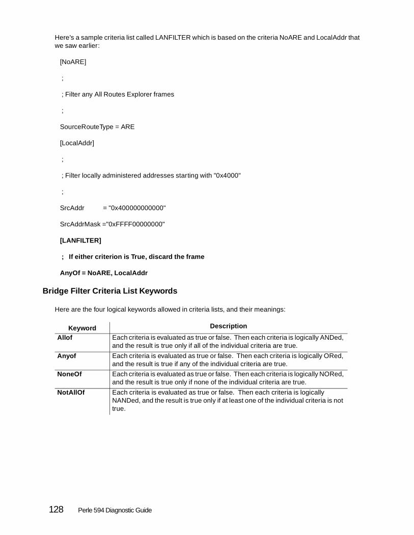
Here's a sample criteria list called LANFILTER which is based on the criteria NoARE and LocalAddr thatwe saw earlier:
[NoARE]
;
; Filter any All Routes Explorer frames
;
SourceRouteType = ARE
[LocalAddr]
;
; Filter locally administered addresses starting with "0x4000"
;
SrcAddr = "0x400000000000"
SrcAddrMask ="0xFFFF00000000"
[LANFILTER]
; If either criterion is True, discard the frame
AnyOf = NoARE, LocalAddr
Bridge Filter Criteria List Keywords
Here are the four logical keywords allowed in criteria lists, and their meanings:
Keyword Description
Allof Each criteria is evaluated as true or false. Then each criteria is logically ANDed, and the result is true only if all of the individual criteria are true.
Anyof Each criteria is evaluated as true or false. Then each criteria is logically ORed, and the result is true if any of the individual criteria are true.
NoneOf Each criteria is evaluated as true or false. Then each criteria is logically NORed, and the result is true only if none of the individual criteria are true.
NotAllOf Each criteria is evaluated as true or false. Then each criteria is logically NANDed, and the result is true only if at least one of the individual criteria is not true.
128 Perle 594 Diagnostic Guide

Creating the Filter
You now know enough to create a filter for the bridge. To do this you have had to:
1. Decide what to filter.
2. Isolate the characteristics that would cause some frames to be discarded and others to be passed.
3. Encode those characteristics as filtering criteria.
4. Logically combine the criteria into lists.
It's now time to identify which criteria lists or criterion will be effective at each side of the bridge or as afilter for the entire bridge.
Filter Syntax
The parts of a bridge filter are:
• The name FILTER enclosed in square brackets, like this: [FILTER]. You must use the word "FILTER". It must be used only once, and nothing else will do
• Optionally, a comment describing the filter on one or more lines, each beginning with a semico-lon character ";".
• One or two filter keywords. Refer to Filter Keywords on page 130 for a list of these keywords
• The logical operator "=" meaning "equal to". (The logical operator, "!=" meaning "not equal to" may not be used in filters.)
• One or more criteria names or criteria list names separated by commas. If you wish to specify that no filter is to be applied to a specific port, leave that port's position empty
Here's a sample filter, based on the criteria and criteria list that we developed earlier:
[NoARE]
;
; Filter any All Routes Explorer frames
;
SourceRouteType = ARE
[LocalAddr]
;
; Filter locally administered addresses starting with "0x4000"
;
SrcAddr = "0x400000000000"
Chapter 4. Use and Creation of Bridge Filter File 129

SrcAddrMask ="0xFFFF00000000"
[LANFILTER]
; If either criterion is True, discard the frame
AnyOf = NoARE, LocalAddr
[FILTER]
;
; On the LAN port, filter out the criteria combined in our
; criteria list, LANFILTER
;
InportList = LANFILTER
Filter Keywords
Keyword DescriptionInPortList This keyword specifies the criteria lists to be used at the ports of the bridge. The first
parameter names the criteria list for the LAN port. The second parameter names the criteria list for the frame relay port. A comma separates the parameters. To indicate that no filtering is to be done, leave that port's position empty. For example InPortList =, FRAMEFILTER has criteria defined for the frame relay port but not the LAN port. InPortList = LANFILTER has criteria defined for the LAN port but not the frame relay port.
GeneralList Specifies the criteria list to be used for the whole bridge. The filtering is done in addition to that specified by the InPortList keyword.
130 Perle 594 Diagnostic Guide

Sample Filters
Since many people learn best by studying examples, here are two examples taken from real networks.
Filtering NetWare IPX traffic
On a typical LAN there are usually many IPX workstations and only one IPX server. Typically you wouldwant to stop the workstations from broadcasting across the bridge, but you would want the server to beable to broadcast, since it needs to communicate with other servers in the NetWare IPX network. Thisexample shows how to keep the NetWare IPX traffic (SNAP format) from crossing the bridge from theLAN to the frame relay WAN, except for traffic from the IPX server, which has a MAC address of"0x400087654321"
The first step is to use the SrcAddr keyword to define a criterion that will allow you to exclude the IPXserver from the other filtering you will define. This can be accomplished by using the negative operator,"!=".
[NotIPXserver]
;
; Define the MAC address of the IPX server that will be allowed to broadcast
; throughout the frame relay WAN
;
SrcAddr!= "0x400087654321"
Next, use the FrameData and FrameDataOffset keywords to define the criterion for filtering IPX frames.The format of IPX frames always contain predictable data beginning with the DSAP field:
DSAP/SSAP = "0xAAAA"
Control Field = "0x03"
SNAP header OUI = "0x000000"
SNAP header PID = "0x8137"
This can be put into a frame data criterion as follows:
[NetWareIPX]
;
; Define the frame data that indicated NetWare IPX frames and the location
; (offset) of the data
;
FrameData = "0xAAAA030000008137"
Chapter 4. Use and Creation of Bridge Filter File 131

FrameDataOffset = 0
Having created the necessary criteria, you can now combine them into a criteria list.
[IPXNotServer]
;
; Filter all NetWare IPX frame except those from the IPX server
;
AllOf = NotIPXServer, NetWareIPX
Finally, you can define the filter, using the criteria list you just created. Notice that no frames are filteredon the frame relay port.
[FILTER]
; Filter all NetWare IPX frames except those from the IPX server on the LAN port.
; Do not filter incoming WAN traffic.
;
InpPortList = IPXNotServer
Remember, all of your criteria, criteria lists, and filter must be included in your filter file.
Filtering TCP/IP ARP Broadcasts
The following example filter can be used to prevent TCP/IP broadcast ARP's from crossing from yourLAN to your WAN port.
We will use the FrameData and FrameDataOffset keywords to define the criterion for filtering TCP/IP ARPframes. The ARP packets over LANs are encapsulated using a SNAP header and is identified by thefollowing fields having the following values:
DSAP/SSAP = "0xAAAA"
Control Field = "0x03"
SNAP header OUI = "0x000000"
SNAP header PID = "0x0806"
[ArpPackets]
;
; Filter criteria for TCP/IP ARP broadcast frames
;
FrameData = "0xAAAA030000000806"
FrameDataOffset = 0
132 Perle 594 Diagnostic Guide

You can now define the filter using just this criterion with no criteria list.
[FILTER]
;
; Filter TCP/IP ARP broadcast messages on the LAN port.
; No filtering is done on the Frame Relay port
;
InPortList = ArpPackets
Editing and Saving 594 Filter File
The 594 uses the bridge filter from an ASCII file that is stored on the 594 system diskette. This file canbe created using any ASCII editor or you can modify the null 594FILT.DAT file that comes on the 594 Utilitydiskette and is installed when you install the 594 Utility program. The maximum size this ASCII filter filecan be, is 10,000 bytes.
To create or change the file:
Step 1 Use any ASCII editor on your PWS. Save the file as 594FILT.DAT.
Step 2 You will also find the file CHKFILT.EXE on both your 594 Utility Program diskettes. This program checks your filter file and reports any errors it finds. CHKFILT is a DOS program and must be run in DOS mode. To execute the CHKFILT program go to the directory in which the 594 Utility program was installed and type:
CHKFILT 594FILT.DAT
These instructions assume you copied your 594FILT.DAT file to the 594 Utility program directory.
When the CHKFILT program finishes executing and there were no errors in your filter file, then you will see the message:
570000 594FILT.DAT
If you have any error in your filter file you will see error codes in the range 570010 to 570200. Refer to Frame Relay Token-Ring Bridge SRCs on page for descriptions of these message codes. If errors are found in the filter file the last message code displayed is:
570001 594FILT.DAT
If you get this message code look at the other message codes previous to this one and correct the errors and run CHKFILT again.
Step 3 To use the bridge filter file it must be transferred to the 594 system diskette. You can transfer the filter file in one the following methods.
• If your have been configuring with the Utility program in interactive mode (either Locally attached or through remote access), then continue to step 4.
• If you have been configuring with the Utility program in stand-alone mode or the NWS
Chapter 4. Use and Creation of Bridge Filter File 133

configuration then refer to Transferring Configuration Data in the 594 User and Reference Guide.
Step 4 From the 594 - Utility program main screen, select Bridge Filter Configuration and press Enter.
594 - Utility Program main screen
Step 5 The 594 - Bridge Filter Configuration screen appears. Select Upload PC Bridge filter file to 594 to transfer the filter file to the 594. This Upload of the bridge filter file can be done while the 594 is in normal or configuration mode.
Step 6 You can also use the Bridge Filter Configuration screen to download the file to the PC at a later time if you want to make any changes to the filter file.
594 - Bridge Filter Configuration screen
134 Perle 594 Diagnostic Guide

Chapter 5. Network Computer Boot Server
This chapter explains some tips and diagnostic functions for the Network Computer Boot Server featureof the 594 Network Controller. This feature is only available with the 594e. Please see the 594 PlanningGuide and the 594e User and Reference Guide for details on the description and use of the NetworkComputer Boot Server feature.
TFTP and FTP Log Files
The 594e has software to run an TFTP and FTP server function. When a Network Computer (NC) isturned on, it will use TFTP or FTP to download files from the 594e hard disk drive. As well, the systemadministrator will use FTP to transfer the NC files to the 594e from the primary boot server. To track theuse of these functions, the 594e can be configured to keep a log file for the TFTP or FTP server.
When the Log file is enabled, all commands and responses for the file transfer servers will be logged toa file. This file will reside in the home directory of the appropriate file transfer server. The Log file will havea maximum size of 10,000 bytes. The file names are:
• TFTP Server tftp.log
• FTP Server ftp.log
When the file reaches the maximum size it will be renamed to have an extension ".old" and a new log filewill be started. When the log file fills up again, the ".old" file will be overwritten with the latest data and anew log file will be started again.
The system administrator can view these files at any time by downloading them from the 594e FTP serverand then using any text editor. The format for the files are as follows:
FTP Log File
mm/dd hh:mm:ss Session n [ip address] - xxxxxxxx "Command/Response"
TFTP Log File
dd/mm hh:mm:ss Session n [ip address] "Command/Response"
where:
• mm/dd is date of the log entry.mm - monthdd - day
• hh:mm:ss is the time of the log entry.hh - hourmm - minutess - seconds
• Session n is the session number that is assigned when the NC makes a connection to the 594e. Use this number to track an NC’s progress through the Log file.
Chapter 5. Network Computer Boot Server 135

• [ip address] is the ip address of the client accessing the TFTP/FTP server. This could be either an NC or a system administrator FTP client.
• xxxxxxxxxx - is the FTP login ID. This will either be the system administrator login name or anonymous.
• Command/Response - is the TFTP/FTP command being executed or the response by the server.
Downloading Files From AS/400
The NC operating system and some application files need to be transferred from the Primary Boot Serverto the 594e. If the primary boot server is an AS/400 host, then the native FTP client included with theAS/400 TCP/IP utilities can perform this function.
However, this can be difficult to use. It is not easy to perform a directory list on the AS/400 and there areno standard tools to create or edit the NC configuration files. It is easier to use a PC running a windowsbased FTP client as an intermediate step between the AS/400 and the 594e. The FTP client on the PCwould be used to download all the required software from the AS/400 to the PC. The software can be putin a specific directory structure and then the whole directory could be download to the 594e.
There are 3rd party windows based FTP clients available that will allow the display of the directories onthe AS/400 and allow the transfer of whole directory structures with one command. These clients alsoprovide a side by side view of the directories of both the remote system (AS/400 or 594e) and the localPC. This can be used to verify that all files have been transferred properly.
136 Perle 594 Diagnostic Guide

Chapter 6. Message Codes
Message codes appear on the bottom left corner of the LCD on the front panel. This chapter describesthese message codes in numerical order. For a full explanation of the Operator Panel LCD, see LCD Message Formats on page 7.
Message Code
Description
000 Indicates the Req key has been pressed. To enter a request command, press a request number, then press Enter . To clear the request command press Esc .
001-01 Power-On Self-Test (POST) is in progress.
001-02 Loading diagnostics from the Perle 594 Controller Setup Diskette.
001-03 Initial program load of Perle 594 system software from the 594 floppy disk drive or 594 hard drive.
002-01 594 failure. Refer to the SRC in the lower right corner of the LCD and see chapter 7 for its meaning.
003-02 Do one of the following:- To run extended diagnostics, insert the 594 Controller Setup Diskette into the disk drive,
press "0" and Enter . - To start system configuration, insert the 594 Controller Setup Diskette into the disk drive,
press "2" and Enter.- To start normal operations, insert the 594 Base Controller Software Diskette or 594
Network Controller Software Diskette into the disk drive, press "1" and Enter.
003-03 The diskette in the Perle 594 diskette drive is not valid or is damaged. Insert the correct diskette, then press Enter to continue. If the invalid diskette is a valid Perle 594 system diskette, then try using the appropriate 594 backup diskette. If the problem continues contact your 594 service representative.
010-05 A post hardware error has been detected. Contact your Perle 594 service representative.
020-01 The extended diagnostics main menu is being displayed.- press "1" to view the Perle 594 hardware features- press "2" to run all hardware tests.- press "3" to set the Perle 594 system date and time- press "4" to configure the Perle 594 hardware.To enter the "Service Mode", press Alt + PF1 .Press Esc to go to 020-02 which restarts the 594.
020-02 Press Enter to restart the Perle 594 in normal mode, or press Esc to continue.
Chapter 6. Message Codes 137

021-xx The Perle 594 feature card slot number and ID is displayed. "xx" refers to the slot number in which the feature card is installed (e.g. 021-01, 021-02,..., 021-07 are the slot numbers of feature cards 1, 2,..., 7). The feature card ID is displayed on the right side of the operator panel LCD. In enhanced mode, there is an upper display that shows the slot number and the card ID. The card ID is the same on the upper line as it is on the lower line. Press Esc to continue.The following lists each card type with its corresponding ID number: Card Type ID Sync (594e) 96 Sync (594T) 97 Twinaxial (495e) 41 ASCII (594e) 42 Token-Ring 43 Double byte Twinaxial (594e) 44 Ethernet 45 Twinaxial 48 Fast Ethernet 49Note: If an unrecognized feature card is encountered, asterisks (**) will be displayed. If
an empty slot is encountered, dashes (—) will be displayed.
021-08 The amount of memory installed on the Perle 594 motherboard is displayed in megabytes on the right side of the bottom line of the operator panel LCD.
021-09 The Perle 594 motherboard type number is shown where Rev 2.0 means 486 type motherboard.
022-04 All Extended Diagnostics hardware tests completed successfully or Req has been pressed to interrupt the tests. Press Enter to continue.
022-05 At least one of the extended diagnostics hardware tests failed. Press Enter to continue. You can view the errors with option 6 (View the Perle 594 time stamped error log) in the Service Mode main menu. See page 115 for more information on the time stamped error log.
023-xx Change or view the current Perle 594 system date and time.- 023-01 change or view the current Perle 594 system date.- 023-02 change or view the current Perle 594 system time.Use the left and right arrow keys on the keypad to move the cursor.Use the numbers on the keypad to change the values.Press Enter to save the value and continue orPress Esc to quit the request without changing the value.- 023-03 the date entered is not valid; press Enter to continue.- 023-04 the time entered is not valid; press Enter to continue.
024-01 The current Token-Ring speed (4 or 16 Mbps), or Ethernet speed (10 or 100 Mbps) of the selected LAN Feature card is displayed on the right side of the operator panel LCD. Use the up and down arrow keys on the keypad to select a new LAN speed. Press the Enter key to complete the Perle 594 setup.
024-02 The Perle 594 setup is complete. Press Esc or Enter to continue.
024-03 Invalid hardware setup due to invalid configuration. Invalid card in wrong slot.
030-01 The "Service Mode" main menu is being displayed. Use the up or down arrow keys or press the number for the options you want and press Enter . Press Esc to exit.- press "1" to view the Perle 594 hardware features- press "2" to run all hardware tests.- press "3" to set the Perle 594 system date and time.- press "4" to configure the Perle 594 hardware.- press "5" to test selected 594 hardware.- press "6" to view the 594 time stamped error log.
138 Perle 594 Diagnostic Guide

030-02 Extended diagnostics test selection menu with key toggle on 1,2,3,4,5,6,7,8,9, if available. Press Esc to return to the "Service Mode" main menu. Press Enter to go to the "Test Option" menu.- press "1" to toggle the test selection on the motherboard.- press "2" to toggle the test selection of the memory.- press "3" to toggle the test selection of the disk drive and the 594e hard drive.- press "4" to toggle the test selection of the front operator panel.- press "5" to toggle the test selection of the Twinaxial card.- press "6" to toggle the test selection of the Token-Ring card.- press "7" to toggle the test selection of the Ethernet card.- press "8" to toggle the test selection of the ASCII card (594e only).- press "9" to toggle the test selection of the Sync card.
030-03 The "Test Option" menu is being displayed.- press "1" to run all selected tests once or until Req is pressed.- press "2" to run all selected tests until an error occurs or Req is pressed.- press "3" to run all selected tests until Req is pressed.To select, press the up or down arrow keys or the option number followed by Enter . Any detected errors will be logged into the Perle 594 time stamped error log. Press Esc to return to the "Service Mode" main menu.Note: While a test is running, it may be necessary to press Req more than once to interrupt testing.
030-04 All extended diagnostics hardware tests have been completed without error or Req was pressed to abort the tests. Press Enter to return to the main menu.
030-05 All extended diagnostics tests have been completed, but at least one of the tests encountered an error. Press Enter to return to the "Service Mode" main menu. Press 6 from the "Service Mode" main menu to view the Perle 594 time stamped error log.
030-06 Confirmation to reboot while in "Service Mode". Press Enter to exit and restart the 594 or press Esc to return to the "Service Mode" main menu.
031-01 The motherboard test is running. Press Req to interrupt the test.
031-02 A hardware problem has been detected during the motherboard test. Refer to the SRC in the lower right corner of the LCD and see chapter 7 for its meaning.
032-01 The memory test is running. Press Req to interrupt the test.
032-02 A hardware problem has been detected during the memory test. Refer to the SRC in the lower right corner of the LCD and see chapter 7 for its meaning.
033-01 Indicates that the disk drive test is running. Press Req to interrupt the test.
033-02 Prompt for the Perle 594 Controller Software Diskette to be entered into the disk drive. Press Enter to continue. Testing the Perle 594 Controller Software Diskette is optional. Press Esc to bypass this test.
033-03 Prompt for the Perle 594 Controller Setup Diskette to be entered into the disk drive. Press Enter to continue.
033-04 Verify that the Perle 594 Controller Diskette's write protect is OFF. Remove the 594 Controller Diskette and verify that the opening in the slot is covered by the tab. If it isn't, slide the tab to the top of the slot so that the opening in the slot is covered. Reinsert the diskette into the drive and press Enter to continue.
033-05 Set the 594 Controller Diskette to write protect ON. Remove the Perle 594 Controller Diskette and verify that the opening in the slot is open. If it isn't, slide the tab to the bottom of the slot so that the opening in the slot is open. Reinsert the diskette into the drive and press Enter to continue.
033-06 Set the Perle 594 Controller Diskette to write protect OFF. Remove the 594 Controller Diskette and verify that the opening in the slot is covered. If it isn't, slide the tab to the top of the slot so that the opening in the slot is covered. Reinsert the diskette into the drive and press Enter to continue.
Chapter 6. Message Codes 139

033-07 Indicates a disk error on the Perle 594 Controller Software Diskette or the Perle 594 Controller Setup Diskette. Refer to the SRC in the lower right corner of the LCD and see chapter 7 for its meaning.To test for a defective disk, put a corresponding backup disk in and try again. If the error occurs again after replacing the diskette, the disk drive may be defective. Press Enter to continue.
033-08 Disk drive error in write protect ON or OFF operations. Refer to the SRC in the lower right corner of the LCD and see chapter 7 for its meaning.
033-09 Indicates that the 594 hard drive test is running. Press Req to interrupt the test.
033-10 Indicates hard drive error during the hard drive test.Refer to the SRC in the lower right corner of the LCD and see chapter 7 for its meaning.
034-01 The front panel test is running. Press Req to interrupt the test.
034-02 Manual keypad test.Press all the keys once except for Enter and Alt .To test the Alt key, press Alt + PF1 .Press Enter twice, once to test the Enter key, and again to end the test.
034-03 Operator panel LCD test.The LCD displays all dots, then all blanks, then the numbers 0-9 and the letters A-F. Press Enter to begin the test and watch the LCD to determine if the sequence is correct. If the pattern displayed is correct, press 1. If the pattern is not correct, press "0" . The sequence is repeated until one of these numbers is pressed.
034-04 Operator panel LED test.The LEDs rotate from the bottom to the top, one at a time. Press Enter to begin the test and watch the LEDs to determine if the sequence is correct. If the sequence is correct, press "1" . If the sequence is not correct, press "0" . The sequence is repeated until one of these numbers is pressed.
034-05 Indicates that an error had occurred in the front panel test. Refer to the SRC in the lower right corner of the LCD and see chapter 7 for its meaning. Press Enter to continue.
035-01 The Twinax card test is running. Press Req to interrupt the test.In enhanced mode, the upper line of the LCD displays the slot number and the ID of the card in that slot.
035-02 A hardware problem was detected on the Twinax card. Refer to the SRC in the lower right corner of the LCD and see chapter 7 for its meaning.In enhanced mode, the upper line of the LCD displays the slot number and the ID of the card in that slot.
036-01 Enter the type of Token-Ring cable being used. Press one of the following options followed by Enter : 1. IBM Cabling System cable (Type 1 or 6) 2. Type 3 media filter cable 3. RJ-45In enhanced mode, the upper line of the LCD displays the slot number and the ID of the card in that slot.
036-02 Enter whether or not a loop-back header is available for use. Press one of the following options followed by Enter : 0 = No 1 = YesIn enhanced mode, the upper line of the LCD displays the slot number and the ID of the card in that slot.
036-03 Disconnect the IBM Cabling System Token-Ring cable from the network, but leave the cable end to the Token-Ring card connected. Press Enter to continue.In enhanced mode, the upper line of the LCD displays the slot number and the ID of the card in that slot.
140 Perle 594 Diagnostic Guide

036-04 Disconnect the Type 3 Media Filter cable and the RJ-45 cable from the Token-Ring card and replace it with the loop-back header. Press Enter to continue.In enhanced mode, the upper line of the LCD displays the slot number and the ID of the card in that slot.
036-05 Diagnostic tests are running and may take up to 2 minutes to complete. Press Req at any time to terminate the tests. Press Req to interrupt the test.In enhanced mode, the upper line of the LCD displays the slot number and the ID of the card in that slot.
036-06 There were no Token-Ring card errors detected. Remove the loop-back header and reconnect the cable to the Token-Ring card and to the network. Press Enter to continue.In enhanced mode, the upper line of the LCD displays the slot number and the ID of the card in that slot.
036-07 No Token-Ring card errors were detected. But because no loop-back header was installed on the Token-Ring card for the Type 3 Media Filter or the RJ-45 cable ports, a complete test was not possible. Press Enter to continue.In enhanced mode, the upper line of the LCD displays the slot number and the ID of the card in that slot.
036-08 Remove the loop-back header from the card and press Enter to continue.In enhanced mode, the upper line of the LCD displays the slot number and the ID of the card in that slot.
036-09 An error has been detected. Refer to the SRC in the lower right corner of the LCD and see chapter 7 for its meaning. Press Enter to continue.In enhanced mode, the upper line of the LCD displays the slot number and the ID of the card in that slot.
036-10 No errors were detected using the IBM Cabling System (types 1 or 6). Reconnect the Token-Ring card to the network and press Enter to continue.In enhanced mode, the upper line of the LCD displays the slot number and the ID of the card in that slot.
037-01 Enter whether or not a loop-back header is available for use. Press one of the following options followed by Enter : 0 = No 1 = YesIn enhanced mode, the upper line of the LCD displays the slot number and the ID of the card in that slot.
037-02 Disconnect the Ethernet cable from the card and replace it with the loop-back header. Press Enter to continue.In enhanced mode, the upper line of the LCD displays the slot number and the ID of the card in that slot.
037-03 Diagnostic tests are running and may take up to 2 minutes to complete. Press Req at any time to interrupt the tests. Press Req to interrupt the test.In enhanced mode, the upper line of the LCD displays the slot number and the ID of the card in that slot.
037-04 No Ethernet card errors were detected. Remove the loop-back header and reconnect the cable to the Ethernet card and to the network. Press Enter to continue.In enhanced mode, the upper line of the LCD displays the slot number and the ID of the card in that slot.
037-05 No Ethernet errors were detected. But because no loop-back header was installed on the Ethernet card, a complete test was not possible. Press Enter to continue.In enhanced mode, the upper line of the LCD displays the slot number and the ID of the card in that slot.
037-06 Remove the loop-back header from the card and press Enter to continue.In enhanced mode, the upper line of the LCD displays the slot number and the ID of the card in that slot.
Chapter 6. Message Codes 141

037-07 An error has been detected. Refer to the SRC in the lower right corner of the LCD and see chapter 7 for its meaning. Press Enter to continue.In enhanced mode, the upper line of the LCD displays the slot number and the ID of the card in that slot.
038-01 Indicate whether or not a loop-back header is available for use. Press one of the following options followed by Enter . 0=No 1=YesIn enhanced mode, the upper line of the LCD displays the slot number and the ID of the card in that slot.
038-02 Disconnect the ASCII cable from the card and replace it with the loop-back header. Press Enter to continue.In enhanced mode, the upper line of the LCD displays the slot number and the ID of the card in that slot.
038-03 The ASCII card test is running. Press Req to interrupt the test.In enhanced mode, the upper line of the LCD displays the slot number and the ID of the card in that slot.
038-04 A hardware problem was detected on the ASCII card. Refer to the SRC in the lower right corner of the LCD and see chapter 7 for its meaning.In enhanced mode, the upper line of the LCD displays the slot number and the ID of the card in that slot.
039-01 The Sync card test is running. Press Req to interrupt the test.
039-02 A hardware problem was detected on the Sync card. Refer to the SRC in the lower right corner of the LCD and see chapter 7 for its meaning.
039-03 The Sync card test detected that no loop-back header is installed.
039-04 Indicate whether or not a loop-back header is installed on the Sync card. Press one of the following options followed by Enter . 0=No 1=Yes
050-01 View the time stamped error log. Press Enter to display the most recent error in the log. Refer to "Viewing the Perle 594 Time Stamped Error Log" section on page 115.
050-02 One or more entries in the time stamped error log does not have a valid time stamp. The problem may be due to an error with the 594 clock when the error was logged. The 594 will continue to operate properly but there will be no time or date recorded for this error log entry. Asterisks will be substituted for the incorrect date and time.
051-xx Indicates which field of the Perle 594 time stamped error log is being displayed on the right-hand side of the LCD.Message Displays051-01 The error count051-02 The date051-03 The time051-04 The SRC051-05 Optional status byte informationTo move between fields, use the left and right arrow keys.For hardware SRC's E00xxx , look up the last 3 digits in chapter 7.For more information about the Perle 594 time stamped error log, see page 121.
052-01 The error log does not contain any entries. Press Esc to return to the main menu.
052-02 The Perle 594 time stamped error log contents have been corrupted. The log has been reinitialized and now contains no errors.
052-03 The storage used to store the Perle 594 time stamped error log is defective. Refer to the SRC in the lower right corner of the LCD and see chapter 7 for its meaning. Error logging information can be unreliable if you continue to use the 594. Press Enter to continue.
142 Perle 594 Diagnostic Guide
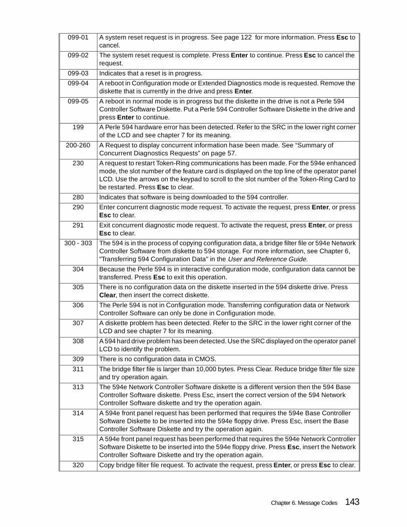
099-01 A system reset request is in progress. See page 122 for more information. Press Esc to cancel.
099-02 The system reset request is complete. Press Enter to continue. Press Esc to cancel the request.
099-03 Indicates that a reset is in progress.
099-04 A reboot in Configuration mode or Extended Diagnostics mode is requested. Remove the diskette that is currently in the drive and press Enter .
099-05 A reboot in normal mode is in progress but the diskette in the drive is not a Perle 594 Controller Software Diskette. Put a Perle 594 Controller Software Diskette in the drive and press Enter to continue.
199 A Perle 594 hardware error has been detected. Refer to the SRC in the lower right corner of the LCD and see chapter 7 for its meaning.
200-260 A Request to display concurrent information hase been made. See “Summary of Concurrent Diagnostics Requests” on page 57.
230 A request to restart Token-Ring communications has been made. For the 594e enhanced mode, the slot number of the feature card is displayed on the top line of the operator panel LCD. Use the arrows on the keypad to scroll to the slot number of the Token-Ring Card to be restarted. Press Esc to clear.
280 Indicates that software is being downloaded to the 594 controller.
290 Enter concurrent diagnostic mode request. To activate the request, press Enter , or press Esc to clear.
291 Exit concurrent diagnostic mode request. To activate the request, press Enter , or press Esc to clear.
300 - 303 The 594 is in the process of copying configuration data, a bridge filter file or 594e Network Controller Software from diskette to 594 storage. For more information, see Chapter 6, "Transferring 594 Configuration Data" in the User and Reference Guide.
304 Because the Perle 594 is in interactive configuration mode, configuration data cannot be transferred. Press Esc to exit this operation.
305 There is no configuration data on the diskette inserted in the 594 diskette drive. Press Clear, then insert the correct diskette.
306 The Perle 594 is not in Configuration mode. Transferring configuration data or Network Controller Software can only be done in Configuration mode.
307 A diskette problem has been detected. Refer to the SRC in the lower right corner of the LCD and see chapter 7 for its meaning.
308 A 594 hard drive problem has been detected. Use the SRC displayed on the operator panel LCD to identify the problem.
309 There is no configuration data in CMOS.
311 The bridge filter file is larger than 10,000 bytes. Press Clear. Reduce bridge filter file size and try operation again.
313 The 594e Network Controller Software diskette is a different version then the 594 Base Controller Software diskette. Press Esc, insert the correct version of the 594 Network Controller Software diskette and try the operation again.
314 A 594e front panel request has been performed that requires the 594e Base Controller Software Diskette to be inserted into the 594e floppy drive. Press Esc, insert the Base Controller Software Diskette and try the operation again.
315 A 594e front panel request has been performed that requires the 594e Network Controller Software Diskette to be inserted into the 594e floppy drive. Press Esc , insert the Network Controller Software Diskette and try the operation again.
320 Copy bridge filter file request. To activate the request, press Enter , or press Esc to clear.
Chapter 6. Message Codes 143

340 Copy Network Controller Software request. To activate the request, press Enter , or press Esc to clear.
345 Display Network Controller Software version request. To activate the request, press Enter , or press Esc to clear.
351 The system file cannot be read from the 594 diskette (either the Perle 594 Controller Software Diskette or the Perle 594 Controller Setup Diskette). Refer to the SRC in the loweright corner of the LCD and see chapter 7 for its meaning.
352 A configuration problem was detected. Refer to the SRC in the lower right corner of the LCD and see chapter 7 for its meaning.
359 Incorrect configuration data was detected. Refer to the SRC in the lower right corner of the LCD and see chapter 7 for its meaning.
361 A configuration problem was detected. Refer to the SRC in the lower right corner of the LCD and see chapter 7 for its meaning.
363 An AS/400 connection error has been detected. Refer to the SRC in the lower right corner of the LCD and see chapter 7 for its meaning.
364 A problem was detected with either the Token-Ring or the Ethernet adapter. Refer to the SRC in the lower right corner of the LCD and see chapter 7 for its meaning.
410 A physical link error has been detected. Refer to the SRC in the lower right corner of the LCD and see chapter 7 for its meaning.
420 An X.25 network error has been detected. Refer to the SRC in the lower right corner of the LCD and see chapter 7 for its meaning.
430 An X.21 network error has been detected. Refer to the SRC in the lower right corner of the LCD and see chapter 7 for its meaning.
440 A V.25 bis error was detected. Refer to the SRC in the lower right corner of the LCD and see chapter 7 for its meaning.
450 An SNA communication error has been detected. Refer to the SRC in the lower right corner of the LCD and see chapter 7 for its meaning.
460 A LAN error has been detected. Refer to the SRC in the lower right corner of the LCD and see chapter 7 for its meaning.
470 Frame-relay error. Refer to the SRC in the lower right corner of the LCD and see chapter 7 for its meaning.
480 A Frame Relay Token-Ring Bridge or IP Routing error has been detected.
500 TCP/IP error. Use the SRC on the LCD display to identify the error.
720 A Perle 594 system failure has been detected. Note any SRCs on the operator panel LCD and contact your 594 service representative.
999 An invalid key has been pressed following the Req key. Press Esc to clear the error and retry the operation.
P01-01 A request to select Perle 594e enhanced mode has been made. Use the arrow keys to select one of the following and press Enter :- press "0" to continue in compatible mode- press "1" to select Perle 594e enhanced mode.
P02-01 A request to delete the Perle 594 configuration data has been made. Use the arrow keys to select one of the following and press Enter :- press "0" and press the Enter key to return without deleting- press "1" and press the Enter key to delete the Perle 594 configuration data.
P24-01 The Perle 594 feature card ID is displayed on the right side of the bottom line of the operator panel LCD. For the 594e enhanced mode, the slot number of the card is displayed on the top line of the LCD. Use the up and down arrows to select the feature card ID to configure. Note: If the Enter key is used to scroll past the last feature card slot, asterisks (**) will be displayed.
144 Perle 594 Diagnostic Guide

P24-02 The current Token-Ring speed or Ethernet speed of the selected LAN Feature card is displayed on the operator panel LCD. The slot number of the card is displayed on the top line of the operator panel LCD. Use the up and down arrow keys on the keypad to select a new LAN speed. Press the Enter key to continue.
P24-03 The configuration data does not match Perle 594 hardware. Refer to the SRC in the lower right corner of the LCD and see chapter 7 for its meaning. Press Enter to correct the configuration data.
Chapter 6. Message Codes 145

146 Perle 594 Diagnostic Guide

Chapter 7. System Reference Codes
This chapter lists System Reference Codes (SRCs) in numerical order along with their descriptions.SRCs may appear on workstation screens and on the front panel in the bottom right corner of the LCD.SRCs are listed in this chapter. While an SRC is being displayed, you can use the right arrow key to see additional codes that will giveyou more information for that SRC. The first number is the test code corresponding to the test that wasbeing performed. Test code descriptions can be found in Appendix B. There may also be a status codethat follows the test code. This status code is for the purpose of identifying the problem if required by aPerle service representative. When viewing the test code, use the left arrow key to return to the SRCpanel. For a full explanation of the Operator Panel LCD, see LCD Message Formats on page 7.
594 System Hardware and Configuration SRC’s (100-199)
The following SRCs indicate hardware problems with the Perle 594:
SRC Description
100 A hardware problem has been detected on the motherboard. Replace chassis.
101 A hardware problem has been detected on the motherboard memory. Replace the motherboard SIMM(s). If the problem persists, replace the chassis.
102(d) A hardware problem has been detected on the diskette or disk drive. d=1 (594 Controller Setup Diskette). d=2 (594 Controller Software Diskette). d=3 (594 Hard Drive)If diskette then try a backup copy of the diskette. If hard drive then retry the test. If the problem persists, the diskette drive or hard drive may be defective.
103 Check the diskette to make sure the write protection tab is set as prompted. If it is and the problem persists, the diskette drive may be defective.
104 A hardware problem has been detected on the front panel. Replace chassis.
105(s) A hardware problem has been detected on the Twinax card in slot s. Replace the Twinax card in slot s with the same type Twinax card (card ID 41, 44, or 48).
106(s) A hardware problem has been detected on the Token-Ring card in slot s. Replace the Token-Ring card in slot s.
107(s) A hardware problem has been detected on the Ethernet card in slot s. Replace the Ethernet card in slot s.
108(s)or
108(s,p)
A hardware problem has been detected on the ASCII card in slot s. When the problem is detected on a particular port, it will be shown as port number p. Replace the ASCII card in slot s.
109(s) A hardware problem has been detected on the Sync card in slot s. Replace the Sync card.
110 A hardware problem has been detected in CMOS memory for the time stamped error log. Replace the Sync card.
111(s) There is a conflict with the setup configuration. Check the switches and straps on the card in slot s and check the config data entered. If the problem persists, replace the card in slot s.
124 Perle 594 system diskette problem detected. Restart the Perle 594 and use the appropriate backup diskette. If the problem continues, contact your 594 service representative.
Chapter 7. System Reference Codes 147

126 No configuration data found for this card. Press the right arrow key on the keypad to display the slot number of the card generating the error.
127 A Perle 594 card failed the self test procedure. Press the right arrow key on the keypad to display the slot number of the card generating the error, and the self test error code. Power the Perle 594 off and on. If the problem continues, contact your 594 service representative.
128 Motherboard memory error detected during power on diagnostics. Power the Perle 594 off and on. If the problem continues, contact your 594 service representative.
129 This card has failed the loopback diagnostics test. Power the Perle 594 off and on. If the problem continues contact your 594 service representative.
130 The card ID assigned during configuration does not match the card installed in the slot. Press the right arrow key on the keypad to display the slot number of the card generating the error.
131 The card ID assigned during hardware setup does not match the card installed in the slot. Press the right arrow key on the keypad to display the slot number of the card generating the error.
132 None of the card IDs have been assigned for Feature Card slots 2 through 7. The card IDs are assigned using the keypad during the hardware setup procedure. Refer to "Appendix D: Installing Perle 594 Feature Cards" in the User and Reference Guide.
133 None of the card IDs have been assigned for the Feature Cards used to communicate with the workstations. The card IDs are assigned using the keypad during the hardware setup procedure. Refer to "Appendix D: Installing Perle 594 Feature Cards" in the User and Reference Guide.
134 All of the configured Feature Cards used to communicate with the workstations have failed the POST procedure. Power the Perle 594 off and on. If the problem continues contact your 594 service representative.
135 None of the card IDs have been assigned for the Feature Cards used to communicate with the Host systems. The card IDs are assigned using the keypad during the hardware setup procedure. Refer to "Appendix D: Installing Perle 594 Feature Cards" in the User and Reference Guide.
136 All of the configured Feature Cards used to communicate with the Host systems have failed the POST procedure. Power the Perle 594 off and on. If the problem continues contact your 594 service representative.
137 No Twinax card has been installed.Therefore, the 594e cannot operate in compatible mode. Use the PC Utility program to configure the 594e in enhanced mode, which can operate with only a LAN gateway.
138 The wrong diskette is in the diskette drive. Use the Base Controller Software Diskette or Network Controller Software Diskette to start up in normal operating mode.
139 There is no configuration file in CMOS or on the Controller Software Diskette. Use Req 300 to restore the configuration file from your backup diskette to CMOS. For information about backing up and restoring the configuration file, refer to the "Configuring from the 594 Utility Program" chapter in the User and Reference Guide.
140 The Perle 594 Controller Setup Diskette was not in the diskette drive when initiation of configuration mode was attempted. Insert the correct diskette in the drive and try again.
141 The Perle 594 Controller Setup Diskette was not in the disk drive when initiation of extended diagnostics mode was attempted. Insert the correct diskette in the drive and try again.
142 The Time-stamped Error Log is invalid. Contact your Perle Systems representative.
143 Insufficient memory for the number of controllers you have assigned. Contact your 594 service representative.
148 Perle 594 Diagnostic Guide

NWS Operational SRC’s (0000-0177)
The following SRCs indicate NWS keyboard errors. To recover from the error, press the Reset or ErrorReset key, correct any problems, and continue.
145 An enhanced hardware setup is being used with a configuration file that is configured for compatible mode.
146 More than 2 LAN cards are installed in the Perle 594. Enter Extended Diagnostics to configure the additional cards.
147 A Perle feature card has been configured with the same slot number as an existing LAN card.
148 The primary Token-Ring card has not been installed in slot 3.
149 The Perle 594 contains a secondary LAN card, but no primary.
150 The synchronous communication card has failed the self test procedure. Power the Perle 594 off and on. If the problem continues, contact your 594 service representative.
151 An invalid twinax card was detected in slot 2 of the 594T.
152 Two (2) unconfigured Token-Ring cards have been installed in the 594e at the same time. See the section Setting the Token-Ring Feature Card Position in Appendix D of the User and Reference Guide for instructions.
153 More than 2 Ethernet LAN cards are installed in the Perle 594.
168(n) Configuration data does not match Perle 594 hardware; (n) indicates the slot number of the card generating this error.
169(n) The Feature Card is not been placed in the correct slot; (n) indicates the slot number of the card generating this error.
170 Insufficient memory for current configuration.
171 No 594 Hard Drive was found. The 594 was started with a Network Controller Software disk but no hard drive was found in the unit.
172 No 594 Networking Controller Software was found on the 594e Hard Drive. Use REQ 340 to load system software onto your 594e hard drive. For more information on installing 594 Networking Controller Software on to the 594e, refer to "Installation of Networking Controller Software" section of the 594e User and Reference Guide.
173 The 594 controller software in the disk drive is not compatible with the 594 hardware.
174 You have configured the 594e to use the PPP protocol but your current hardware does not support PPP. Check the serial number of the controller, if it is lower than 59-08000, it indicates that you need to upgrade the Synchronous Communication Card in order to run PPP.
199 The test code corresponding to the testing error is not found in the test code table.
SRC Description
0000 Help key is not valid.
0001 Keyboard overrun.
0002 Invalid scan code.
0003 Invalid key followed CMD or ALT key.
0004 Only data from a magnetic stripe reader or a light pen is allowed.
0005 Cursor in protected area of display.
0006 Invalid key followed System Request key.
0007 Mandatory entry field not filled in.
Chapter 7. System Reference Codes 149

0008 Only alphabetical data is allowed.
0009 Only numeric data allowed.
000G Secondary session not available at this time; session power down in progress. Retry this request when the power down is completed.
000H Hot key to secondary session failed; either the session has not been configured or the session could not be allocated during power up.
0010 Only characters 0 through 9 allowed.
0011 Key not allowed in last position of signed numeric field.
0012 No room to insert data in the field.
0013 Terminal still in insert mode; only data keys allowed.
0014 Mandatory fill field; must be filled or empty.
0015 Self-check field error.
0016 Field- not valid for this field.
0017 Mandatory field must be filled or empty.
0018 You pressed a data key to exit a nondata field. To exit this field, use Field Exit.
0019 Dup or Field Mark key not permitted.
0020 You pressed a function key that is not valid in a right-adjust field. To exit this field press Field -, Field +, or Field Exit.
0021 Data must be entered in mandatory enter field.
0022 System error.
0023 Hexadecimal mode error.
0024 Invalid key; only 0 through 9 and Dup key allowed.
0026 Field- entry not allowed; last position must be 0 through 9.
0027 Key not valid on this display station.
0028 Key not valid on this display station.
0029 Diacritic character not valid.
0031 Data buffer overflow.
0032 Magnetic stripe reader, invalid data.
0033 Magnetic stripe reader, data not authorized.
0034 Magnetic stripe reader, data exceeds field length.
0035 Magnetic stripe reader, card cannot be read.
0036 Cursor select not allowed in field exit mode.
0037 Cursor select not allowed in a non-selectable field.
0038 Magnetic stripe reader or light pen not allowed for this field.
0040 Modem or DCE Not Ready.Data Set Ready (DSR) Line Inactive for V.24 or V.35, or DCE Not Ready for X.21.This error indicates that the modem or DCE was not ready during required intervals of normal operation. The operating state of the modem or DCE is checked at different times, depending on the specific link-level protocol in use.
0041 The receive line was idle for at least 15 bit times. Verify all cable and line connections. If the problem persists, contact the network administrator.
0042 The receive clock signal from the modem or DCE is not being received. Verify all cable and line connections. If the problem persists, contact the network administrator.
150 Perle 594 Diagnostic Guide

0043 The data set ready (DSR) signal was not deactivated by the modem or DCE even though the 594 tried to disconnect from the line. Verify all cable and line connections. If the problem persists, contact the network administrator.
0044 30-Second Timeout.For a synchronous connection this error indicates that no valid data has been received for 30 seconds. For a LAN connection this error indicates the Ti timer has expired before a valid frame was received by the Perle 594.
0045 During link setup, either a disconnect mode (DM) or disconnect (DISC) command signal was received; the DCE will not become activated. Verify all cable and line connections. If the problem persists, contact the network administrator.
0046 Frame reject received. The Perle 594 received a FRMR from the network. Verify all cable and line connections. If the problem persists, contact the network administrator.
0047 The Perle 594 received an unexpected disconnect mode or disconnect command. Verify all cable and line connections. If the problem persists, contact the network administrator.
0048 An unexpected Unnumbered Acknowledgment (UA) frame was received. Verify all cable and line connections. If the problem persists, contact the network administrator.
0049 The Perle 594 received an unexpected SABME. Restart communication, if the problem persists, contact the network administrator.
0050 An error was detected in the Ready For Sending (RFS) or Clear To Send (CTS) signal. Verify all cable and line connections. If the problem persists, contact the network administrator.
0051 The transmit clock failed during a transmit operation. If the problem persists, contact the network administrator.
0052 No transmit clock, modem, or DCE signal was detected even though the link adapter did not complete a transmit operation within the allotted time period. Verify all cable and line connections. If the problem persists, contact the network administrator.
0053 Expiration of Retry Counter (X.25 only).No acknowledgment of a transmission was received within the allowed timeout. (Timeout retry counter (N2) and retry interval (T1) are specified in Field 7 of the NWS configurator.)
0054 Frame reject sent. The Perle 594 has sent a FRMR response to the AS/400 system after receiving an invalid DLC or LAPB command.
0055 The Perle 594 has determined that the communication cable is not attached to the 594. Attach a cable to the 594 or replace the one currently attached.
0056 Link was broken between the Perle 594 and the host. Ensure that delays and timer values are sufficiently long. If the problem persists, contact the network administrator.
0060 Alphanumeric character entered into double-byte data characters or a key that is invalid within an embedded segment was pressed.
0061 Double-byte character entered into an alpha numeric field or a key that is invalid outside an embedded segment was pressed.
0062 Change data type not allowed; the cursor must be in an open field or in the first position ideographic field.
0063 Invalid ideographic character entered while in alternate entry mode.
0064 Invalid key pressed for the current keyboard mode.
0065 Invalid cursor position; column reserved for shift-out or shift-in characters.
0066 Repeat key not valid at current position.
0067 Workstation extension character RAM is full. Therefore, additional extension characters will be displayed as default characters.
0068 Perle 594 output data stream is not valid for extension characters. Therefore, any additional extension characters will be displayed as default characters.
Chapter 7. System Reference Codes 151

0069 Perle 594 output data stream contains invalid or undefined extension characters. Additional extension characters will be displayed as default characters.
006G Invalid terminal type. A double byte character terminal is attached to a Twinaxial Feature Card with Card ID 41. A card with Card ID 44 must be used.
0070 Word spill or carrier return error.
0071 Invalid start copy, move, or delete text operation while a previous operation is still in progress.
0072 Invalid key pressed for the current cursor position.
0073 Invalid instruction attempted while the general prompt function was not active.
0074 Invalid key pressed while the general prompt function is active.
0075 Keyed characters not found.
0076 Insert function failed; the AS/400 has not processed the text on the screen.
0077 Invalid function key pressed or a 3270 keyboard function was entered while in word processing mode.
0078 Application error; the required scale line is not defined for your workstation.
0081 Configuration error; there are too many devices attached.
0082 Invalid keyboard function.
0083 Invalid selection.
0084 Selection field unavailable.
0087 Flow control error. Be sure X.25 communication settings on the Perle 594 match X.25 communication worksheet.
0089 One or more required fields not complete.
008A One or more fields contain an invalid embedded blank.
008B Too many keyboard country codes defined; four is the maximum.
008C Duplicate values configured error. One of the following duplicate values have been configured:
• Two or more hosts have been given the same fully qualified name (Hx:1 joined together with Hx:2). If concurrent host is enabled, each host must have a unique, fully qualified name.
• A FR-TR Bridge DLCI is the same as another FR-TR bridge DLCI or the same as a Host DLCI.
• The frame relay ring number and LAN ring number are the same on a FR-TR bridge configuration.
• The frame relay MAC address and the 594A token-ring LAN address are the same on a FR-TR bridge configuration
008D The printer port and/or station address values are invalid.
008E One or more fields contain an insufficient number of characters.
008F One or more fields contain a value outside the valid range.
008G NWS configuration can be accessed either on either slot 2 or slot 4.
008H Perle 594 hardware setup for enhanced mode only. You must use the PWS configuration to modify your configuration data.
008J Perle 594 configuration file valid for enhanced mode only. You must use the PWS configuration to modify your configuration data.
0091 The Reverse and Close keys are not valid for this field.
0092 The Reverse key is not valid on this display because it is configured for shared addressing.
152 Perle 594 Diagnostic Guide

Twinax Display SRCs (0100—0191)
These SRCs relate to twinaxial workstations. When these SRCs appear on the time-stamped error log,they are prefixed with 2 leading zeros (00).
0097 Test request not supported by the host system.
0098 Hardware error.
0099 In operating mode, the requested function is not supported or there is no session with AS/400 system established. In configuration mode, only one device can be in configuration mode at any time. Another device is currently active in the configuration program.
009A Three invalid passwords have been entered on this PWS.
009G The default word processing message table is currently active for this session. All word processing functions are available.
009H The 594 requires additional system memory to operate with the current configuration. Only the primary session(s) will be active; multisession(s) will not be available.
SRC Description
0100 There is a problem with an attached workstation. This SRC is reported if the workstation does not respond to a POLL within 200 µsec.
0101 The 594 has detected one or more bit errors in data transmitted (transmit activity check) to an attached workstation.
0103 There is a problem with an attached workstation. The wrong parity was received in response to a POLL or ACTIVATE RECEIVE command.
0104 A workstation has detected a parity error in data transmitted by the 594.
0105 The addressed workstation is unable to respond because another workstation on the same twinaxial line is continuously transmitting.
0106 The 594 received, from an attached workstation, the wrong number of bytes as a result of a POLL or ACTIVATE RECEIVE command.
0107 An incorrect station address was returned in response to a POLL or other command from the 594.
0108 The workstation's power-on transition status bits are set, indicating the workstation is currently going through power-up even though power-up has already been completed.
0109 The 594 checked the device status of an attached workstation and found that the busy bit was not ON after an ACTIVATE WRITE command.
0111 The 8-bit code sent by an attached workstation in the keyboard response frame could not be translated to a character or a function by the 594.
0120 A POLL or other command sent to a workstation was not valid; or the device ID was incorrect.
0121 The address counter value was not within the user accessible limits.
0122 Storage or input queue overrun. More than 16 commands and associated data frames were sent to the workstation by the 594; or an attempt was made to store data in storage that is not accessible to the user.
0123 Attribute was not found; or the address counter pointed to an attribute.
0124 An ACTIVATE command sent to the workstation was invalid.
0125 In response to a POLL, a workstation has returned to an undefined exception status.
0126 An incorrect or unexpected pass-through command was detected.
Chapter 7. System Reference Codes 153

0149 The 594 received an invalid POLL response.
0170 A workstation did not detect the end of a printer definition table (PDT). Sense data is 00.
0172 A workstation detected invalid data in the printer definition table (PDT) sent to it from the AS/400 system. Sense data is 00ccxxyyyyyyyy, where cc is the command code of the definition containing invalid data, xx is the offset in bytes from the command to the invalid data, and yyyyyyyy is additional error data.
0173 A workstation received from the AS/400 system a printer definition table (PDT) that was larger than the maximum allowable size. Sense data is 00xxxxyyyy, where xxxx is the workstation's maximum PDT size, and yyyy is the size of the PDT sent to the workstation.
0176 A workstation received an erroneous microcode correction file from the AS/400 system. The sense data defines the error as follows: 001 The workstation failed to detect the end of the file. 0002yyyyyyyy The workstation detected data not valid in the file. yyyyyyyy = Additional error data 0003xxxxyyyy The size of the file is too large for the workstation. xxxx = Workstation's maximum file size yyyy = Size of the file sent to the workstation
0177 A workstation received an erroneous font file from the AS/400 system. Sense data defines the error as follows: 001 The workstation failed to detect the end of the file. 0002yyyyyyyy The workstation detected data not valid in the file. yyyyyyyy = Additional error data 0003xxxxyyyy The size of the file is too large for the workstation. xxxx = Workstation's maximum file size yyyy = Size of the file sent to the workstation
0181 One of the following errors has occurred: an MSR-detected error, a longitudinal redundancy check (LRC) error, or a 594-detected parity error.
0182 A workstation responded to a READ DEVICE ID command without setting a valid device-type code.
0183 The display screen image size does not match the image size in the ID word sent by the workstation.
0184 The keyboard ID received by the 594 was invalid.
0189 An outstanding status bit was set in the POLL response, but no outstanding status information was available.
0190 The workstation status did not change within 7 seconds after a not-busy response was returned to a positive acknowledge poll.
0191 The 594 detected that the busy bit had been on for more than 1.6 minutes.
154 Perle 594 Diagnostic Guide

Twinax Printer and Unknown Twinax Device SRCs (0200—03xx)
These SRCs relate to twinaxial printers. When these SRCs appear on the time-stamped error log, theyare prefixed with 2 leading zeros (00).
SRC Description
0200 An attached printer failed to respond to a poll within 200 µsec.
0201 The 594 has detected one or more bit errors in a transmission (transmit activity check) to an attached printer.
0203 The 594 has detected a parity error in response to a POLL or ACTIVATE RECEIVE command.
0204 A printer has detected a parity error in data transmitted by the 594.
0205 The addressed printer is unable to respond because another workstation on the same twinaxial line is continuously transmitting.
0206 The 594 has received the wrong number of bytes from a printer as a result of a POLL or ACTIVATE RECEIVE command.
0207 The 594 has received a response to a POLL or other command with an incorrect station address.
0208 The printer's power-on transition status bits are set, indicating the printer is currently going through power-up even though power-up has already been completed.
0209 The 594 checked the device status and found that the busy bit was not on after an ACTIVATE WRITE command.
021X The printer did not process an incoming data stream correctly. This error is device-dependent.
0220 An attached printer received a command having an incorrect command code or device ID.
0221 An attached printer returned an exception status of 110, which is invalid for this AS/400 system.
0222 A printer received more than 16 frames of commands and associated data (more than 256 frames total) from the 594, resulting in a storage or input queue overrun.
0223 The addressed printer did not respond to a valid ACTIVATE command and the associated data stream.
0224 The addressed printer has detected that the 594 transmitted the wrong ACTIVATE command.
0225 An attached printer returned an exception status of 011, which is invalid for this AS/400 system.
0226 The addressed printer detected a character code in the data stream that it does not support and, therefore, could not print the character.
0228 The addressed printer detected an invalid SNA character string (SCS) command in the data stream sent by the AS/400 system.
0229 The addressed printer detected an invalid SCS parameter in the data stream sent by the AS/400 system.
023X-024X The addressed printer has an internal failure. These errors are device-specific.
0249 The 594 received an invalid POLL or READ response from the addressed printer.
025X These errors are reported periodically to the 594 0250 End of form 0251 Unit not available or not ready 0258 End of ribbon
Chapter 7. System Reference Codes 155

fails, an indicate
X.25 Communication SRC’s (100000-1BFF00 )
If you are using X.25 communication and an error occurs during the keyboard entry of a command, optionor parameter, a 6-digit SRC between 100000 and 10FFFF is displayed.
If the controller accepts the keyboard-entered options but the network operation with the AS/400 system SRC between 110000-1BFF00 is displayed on all display stations attached to that controller. These SRCsa communication network problem at the packet level.
0260 An Intelligent Printer Data Stream (IPDS) printer has multiple status. The AS/400 system must return a READ MULTIPLE STATUS command to initiate readout.
026X The addressed printer detected errors in the data stream from the AS/400 system. These error codes are device-specific.
028X The addressed printer has a hardware condition that halted printout. These error codes are device-specific.
03xx Unknown device error. These error codes occur when a twinaxial device is not yet recognized to be either a printer or a display.
SRC Description
100000 Previous X.25 command still be executed.
100100 A virtual circuit has already been established. The Perle 594 can only communicate over one virtual circuit per controller at a time.
100200 An answer command was entered for a PVC circuit. A PVC circuit requires an open command.
100300 A call command was entered for a PVC circuit. A PVC circuit requires an open command.
100400 The logical channel ID is not valid because it is not three characters long.
100500 The logical channel ID option is not valid because it is not a hexadecimal value between 001 and FFF.
100600 The password option is not valid because it is longer than eight characters or contains non-alphanumeric characters.
100700 The host network address is not valid because it is longer than 15 decimal digits or contains non-numeric characters.
100A00 The operator attempted to enter option fields not supported by that connection type.
100B00 The X.25 facility entered contains invalid characters.
100C00 The X.25 packet window size entered is invalid because it is less than 02.
100D00 The X.25 packet window size entered is invalid because modulo 8 is specified and the packet size is greater than 07.
100E00 The X.25 packet window size entered is invalid because modulo 128 is specified and the packet size is greater than 15.
100F00 The X.25 packet size is not equal to 64, 128, 256, or 512.
101000 The X.25 closed user group option does not contain 2 decimal digits.
101100 An invalid control character was entered.
101300 For X.25: Either a) the first control character entered was not one of A, O, C, or D or b) the first control character has already been entered.
101500 The password option was entered for a PVC.
101600 The X.25 password is invalid because it contains characters that are not alphanumeric.
156 Perle 594 Diagnostic Guide

SRCs 110000—1100FF
The controller issued a clear request packet after detecting an error.
101800 The X.25 closed user group option was entered for a command that was not a CALL command issued on an SVC.
101900 The option Q (QLLC) or E (ELLC) is not valid with an answer command. Use these options with an SVC call or PVC open command.
101A00 The X.25 F or R option was entered for a command that was not initiating a CALL command on an SVC.
101B00 The recovery value for the E (ELLC) option must be from 100 to 199.
101C00 A CALL command was entered for an answer-only SVC. The 594 configuration may be incorrect.
101D00 An open command was entered for a manual connect SVC controller.
SRC Description
110000 No additional information.Report the problem to your AS/400 system operator.
110014 The Perle 594 received an X.25 packet type that is invalid for state p1 and issued a Clear Request.
110015 The Perle 594 detected an X.25 packet type that is invalid for state p2 and issued a Clear Request.
110017 The Perle 594 detected an X.25 packet type that is invalid for state p4 and issued a Clear Request.
110018 The Perle 594 detected an X.25 packet type that is invalid for state p5 and issued a Clear Request.
110031 The Perle 594 issued an X.25 Clear Request because a Call Connected was not received within 200 seconds. Contact the X.25 network service provider.
110032 The Perle 594 issued an X.25 Clear Request because a Clear Confirmation was not received within 200 seconds. Contact the X.25 network service provider.
110046 Call from unexpected DTE.Verify the network address and retry. If the problem continues, report the problem to your AS/400 system operator.
110050 A general ELLC/QLLC error has occurred. Report the problem to the AS/400 system operator.
110051 An undefined ELLC C-field was detected. Report the problem to the AS/400 system operator.
110054 An undefined ELLC I-field was detected. Report the problem to the AS/400 system operator.
110055 An I-field that was longer than the allowed 521 bytes was detected. Report the problem to the AS/400 system operator.
110056 An error occurred and an ELLC frame reject was received. Report the problem to the AS/400 system operator.
110057 An invalid ELLC header was detected. Report the problem to the AS/400 system operator.
110059 An ELLC timeout condition was detected. Report the problem to the AS/400 system operator.
11005A An invalid ELLC receive sequence count was detected. Report the problem to the AS/400 system operator.
11005B An ELLC recovery was rejected or terminated.
Chapter 7. System Reference Codes 157

1100A1 The Perle 594 detected an invalid X.25 M-bit packet sequence and, therefore, issued a Clear Request. Be sure the packet size entered matches the packet size specified in the network subscription.
1100A6 The Perle 594 detected an X.25 packet that was too short and, therefore, issued a Clear Request. Be sure the packet size entered matches the packet size specified in the network subscription.
1100A7 The Perle 594 detected an X.25 packet that was too long and, therefore, issued a Clear Request. Be sure the packet size entered matches the packet size specified in the network subscription.
1100AA The Perle 594 detected an unsupported, X.25 interrupt packet and, therefore, issued a Clear Request. Contact the X.25 network service provider.
1100AB The Perle 594 detected an invalid X.25 packet send sequence number (Ps) and, therefore, issued a Clear Request. Contact the X.25 network service provider.
1100AC The Perle 594 detected an invalid X.25 packet receive sequence number (Pr) and, therefore, issued a Clear Request. Contact the X.25 network service provider.
1100AD The Perle 594 received an invalid X.25 D-bit and, therefore, issued a Clear Request. Report the problem to the AS/400 system operator.
1100D0 The Perle 594 received an X.25 general resources error and, therefore, issued a Clear Request. Report the problem to the AS/400 system operator.
1100D2 The Perle 594 received an X.25 path information (PIU) that was too long and, therefore, issued a Clear Request. Report the problem to the AS/400 system operator.
1100E0 An invalid facility length was detected. Report the problem to the AS/400 system operator.
1100E6 Unsupported facility parameters were detected. Report the problem to the AS/400 system operator.
1100E7 An unsupported facility was detected. Report the problem to the AS/400 system operator.
1100E8 A call from an unexpected DTE was detected. Retry the operation.
1100E9 The Perle 594 detected an invalid X.25 D-bit and, therefore, issued a Clear Request. Report the problem to the AS/400 system operator.
1100EA An error was detected, and there was a reset indication on an SVC.
1100EB An invalid protocol identifier was detected. Retry the operation.
1100EC A password mismatch was detected. Retry the password.
1100F4 Connection rejection; reason unspecified (transient condition).Retry the operation. You should report the problem to your AS/400 system operator.
1100F5 Connection rejection; reason unspecified (permanent condition).Retry the operation. You should report the problem to your AS/400 system operator.
1100F6 Connection rejection; requested quality of service not available (transient condition).Verify your configuration. If the problem continues, report the problem to your network representative.
1100F8 Connection rejection; incompatible information in user data.Verify your configuration. If the problem continues, report the problem to your network representative.
158 Perle 594 Diagnostic Guide

SRCs 120000—1200FF
The controller issued a reset request packet after detecting an error.
SRC Description
120000 No additional information.Report the problem to your AS/400 system operator.
120001 Invalid packet sent sequence number (Ps).Report the error to your network representative.
120002 Invalid packet received sequence number (Pr).Report the error to your network representative.
12001B Invalid packet type for state d1.Retry the operation. You may be allowed temporary operation. However, you should report the error to your network representative.
120020 Packet not allowed.Report the problem to your AS/400 system operator.
120026 Packet too short.Make sure that the packet size entered in the configuration or entered manually matches your network subscription.
120027 Packet too long.Make sure that the packet size entered in the configuration or entered manually matches your network subscription.
120033 Reset confirmation not received within 200 seconds.Report the problem to the AS/400 system operator.
120050 A general ELLC/QLLC error has occurred. Report the problem to the AS/400 system operator.
120051 An undefined ELLC C-field was detected. Report the problem to the AS/400 system operator.
120054 An undefined ELLC I-field was detected. Report the problem to the AS/400 system operator.
120055 An I-field that was longer than the allowed 521 bytes was detected. Report the problem to the AS/400 system operator.
120056 An error occurred and an ELLC frame reject was received. Report the problem to the AS/400 system operator.
120057 An invalid ELLC header was detected. Report the problem to the AS/400 system operator.
120059 An ELLC timeout condition was detected. Report the problem to the AS/400 system operator.
12005A An invalid ELLC receive sequence count was detected. Report the problem to the AS/400 system operator.
12005B An ELLC recovery was rejected or terminated.
1200A1 The Perle 594 detected an invalid X.25 M-bit packet and, therefore, issued a Reset Request. Ensure packet size entered matches packet size in network subscription.
1200A6 The Perle 594 detected an X.25 packet that was too short and, therefore, issued a Reset Request. Ensure packet size entered matches packet size in network subscription.
1200A7 The Perle 594 detected an X.25 packet that was too long and, therefore, issued a Reset Request. Ensure packet size entered matches packet size in network subscription.
1200AA The Perle 594 detected an X.25 unsupported interrupt packet and, therefore, issued a Reset Request. Contact the network service provider.
1200AB The Perle 594 detected an invalid X.25 packet send sequence number (Ps) and, therefore, issued a Reset Request. Contact the network service provider.
Chapter 7. System Reference Codes 159

SRCs 1800zz—18FFzz
The DCE issued a clear indication packet after detecting an error.
Note: Most diagnostic codes (zz) are issued by the network and may vary from network to network. The diagnostic codes (zz) are defined later in this section.
1200AC The Perle 594 detected an invalid X.25 packet receive sequence number (Pr) and, therefore, issued a Reset Request. Contact the network service provider.
1200AD The Perle 594 detected an invalid X.25 D-bit and, therefore, issued a Reset Request. Report the problem to the AS/400 system operator.
1200D0 The Perle 594 detected an X.25 general resources error and, therefore, issued a Reset Request. Report the problem to the AS/400 system operator.
1200D2 The Perle 594 detected an X.25 path information unit (PIU) that was too long and, therefore, issued a Reset Request. Report the problem to the AS/400 system operator.
1200F4 General resources.Retry the operation. Other applications may operate normally. However, you should report the error to your AS/400 system operator.
1200F5 PIU too long.Retry the operation. Other applications may operate normally. However, you should report the error to your AS/400 system operator.
SRC Description
1800zz Call clearing originated at AS/400 system.Report the problem to the AS/400 system operator.
1801zz AS/400 system busy.Wait, then retry the operation.
1803zz Invalid facility request.Verify the request. Report the problem to your network representative.
1805zz Network congestion.Retry the operation. If the problem continues, report the problem to your network representative.
1809zz Out of order—AS/400 system not ready.Wait, then retry the operation. If the problem continues, report the problem to your network representative.
180Bzz Access to the AS/400 system not allowed.Verify the request. Report the problem to your AS/400 system operator.
180Dzz Unrecognized AS/400 system network address.Verify the request. Report the problem to your AS/400 system operator.
1811zz Error at the AS/400 system.Report the problem to your AS/400 system operator.
1813zz Error at the Perle 594 controller.Verify the request. Report the problem to your network representative.
1815zz Recognized Private Operating Agency (RPOA) out of order.Verify the request. Report the problem to your network representative.
1819zz Reverse charging not subscribed.Verify the request. Report the problem to your network representative.
1821zz Incompatible destination.Verify the request. Report the problem to your network representative.
1829zz Fast select not supported.Verify the request.
160 Perle 594 Diagnostic Guide

SRCs 1900zz—19FFzz
The DCE issued a reset indication packet after detecting an error.
Note: Most diagnostic codes (zz) are issued by the network and may vary from network to network. The diagnostic codes (zz) are defined later in this section.
1841zz Gateway-detected procedure error. Repeat the operation. Report the problem to the network representative.
1843zz Gateway congestion error. Repeat the operation. Report the problem to the network representative.
1880zz Call clearing originated at target X.25 DTE. Report the problem to the system operator.
1881zz Target X.25 DTE is busy. Verify the call. Report the problem to the system operator.
1883zz Invalid facility request. Verify the facility. Report the problem to the network representative.
1885zz Network is congested. Repeat the operation. Report the problem to the network representative.
1889zz Target X.25 DTE is not ready. Verify the call. Report the problem to the system operator.
188Bzz Access to selected target X.25 DTE denied. Verify the link and configuration. Report the problem to the system operator.
188Dzz Target X.25 DTE network address is not recognized. Verify the address. Report the problem to the system operator.
1891zz Error at target X.25 DTE. Report the problem to the system operator.
1893zz Error at the Perle 594.
1895zz Recognized private operating agency (RPOA) is out of order. Verify the RPOA. Report the problem to the network representative.
1899zz Reverse charging not subscribed to. Report problem to the network representative.
18A1zz Incompatible destination. Verify the link and address. Report the problem to the network representative.
18A9zz Fast select not subscribed to. Verify the link.
18C1zz Gateway-detected procedure error. Wait and retry the operation. Report the problem to the network representative and the system operator.
18C3zz Gateway congestion error. Wait and retry the operation. Report the problem to the network representative and the system operator.
SRC Description
1900zz Reset originated at AS/400 system.
1901zz Out of order—disconnected AS/400 system.
1903zz Error at the AS/400 system.
1905zz Error at the controller.
1907zz Network congestion.
1909zz Remote DTE operational. This is not an error; it is a normal condition at startup.
190Fzz Network operational. This is not an error; it is a normal condition at startup.
1911zz Incompatible destination.
191Dzz Network out of order.
1980zz Call clearing from the target X.25 DTE.
Chapter 7. System Reference Codes 161

SRCs 1A00zz—1AFFzz
The DCE issued a restart.
Note: Most diagnostic codes (zz) are issued by the network and may vary from network to network. The diagnostic codes (zz) are defined later in this section.
18yyzz - 1Ayyzz (zz) Diagnostic Codes
The following are the diagnostic codes (zz) for 18yyzz, 19yyzz, and 1Ayyzz:
1981zz Disconnected target X.25 caused an out of order.
1983zz Error at the target X.25.
1985zz Error at the Perle 594.
1987zz Network congestion.
1989zz Remote DTE is operational. This is not an error; it is a normal condition at startup.
198Fzz The network is operational. This is not an error; it is a normal startup condition.
1991zz Incompatible destination.
199Dzz Network is out of order.
SRC Description
1A00zz No additional information.
1A01zz Local procedure error.
1A03zz Network congestion.
1A07zz Network is operational. This is not an error; this is a normal condition at startup.
1A7Fzz Registration or cancellation confirmed. This is not an error.
Diagnostic Code (zz) Description
00 No additional information.
01 Send sequence — P (s) not valid.
02 Received sequence — P (r) not valid.
10 Packet type not valid.
11 State r1.
12 State r2.
13 State r3.
14 State p1.
15 State p2.
16 State p3.
17 State p4.
18 State p5.
19 State p6.
1A State p7.
162 Perle 594 Diagnostic Guide

1B State d1.
1C State d2.
1D State d3.
20 Packet not allowed.
21 Unidentifiable packet.
22 Call on one-way logical channel.
23 Invalid packet type on a permanent virtual circuit.
24 Packet on unassigned logical circuit.
25 Reject not subscribed to.
26 Packet too short.
27 Packet too long.
28 Invalid general format identifier.
29 Restart with LCID not equal to hexadecimal 000.
2A Packet type not compatible with facility.
2B Unauthorized interrupt confirmation.
2C Unauthorized interrupt.
2D Unauthorized reject.
30 Timer expired, general.
31 Timer expired for incoming call.
32 Timer expired for clear indication packet.
33 Timer expired for reset indication packet.
34 Timer expired for restart indication packet.
40 Call setup or call clearing problem.
41 Facility code not allowed.
42 Facility parameter not allowed.
43 Invalid called address.
44 Invalid calling address.
45 Invalid facility/registration length.
46 Incoming call barred.
47 No logical channel available.
48 Call collision.
49 Duplicate facility requested.
4A Non-zero facility address.
4B Non-zero facility length.
4C Facility not provided when expected.
4D Invalid CCITT-specified DTE facility.
50 Miscellaneous problems.
51 Improper cause code from DTE.
52 Octet not aligned.
53 Inconsistent Q bit setting.
Chapter 7. System Reference Codes 163

SRCs 1B0000—1BFF00The controller issued a restart request packet after detecting an error.
Note: Most diagnostic codes (zz) are issued by the network and may vary from network to network. The diagnostic codes (zz) are defined later in this section.
Point To Point Protocol SRCs (1C000 - 1C00FF)When using the PPP protocol to communicate with the host, the following conditions will be reported:
70 International problem.
71 Remote network problem.
72 International protocol problem.
73 International link out of order.
74 International link busy.
75 Transit network facility problem.
76 Remote network facility problem.
77 International routing problem.
78 Temporary routing problem.
79 Unknown called DNIC.
7A Maintenance action.
80 - FF Network-specific diagnostic information.
SRC Description
1B1100 Unsolicited restart confirmation received.
1B2400 LCID=0 non-restart/diagnostic packet.
1B2800 Invalid GFI (restart indication/confirmation only).
1B2900 LCID is not equal to 0 on restart indication/confirmation.
1B3400 Restart confirmation packet not received within 200 seconds.
1BA5yy Diagnostic packet was received.
1BA600 Packet is too short.
1BA700 Packet is too long.
1BA800 General format identifier (GFI), restart indication, or confirmation not valid.
1BE200 Restart indication/confirmation packet logical channel identifier (LCID) is not equal to 0.
1BE500 Non restart/diagnostic packet logical channel identifier (LCID) is equal to 0.
SRC Descri ption
1C0000 No Data Set Ready (DSR) detected from the modem.
1C0001 Busy signal detected, the connection could not be established.
1C0002 No dial tone detected, the connection could not be established.
1C0003 No ring indicator, the connection could not be established.
1C0004 Unable to initialize the modem.
1C0010 Carrier has been lost unexpectedly during connect state
1C0011 Unable to process the link disconnect request because the link is already in the process of being disconnected
164 Perle 594 Diagnostic Guide

X.21 Switched Communication SRCs (200000-250300)
If the controller accepts the keyboard entered options but the network operation with the AS/400 systemfails, an SRC indicating the type of communication problem code is displayed on all the display stationsattached to that controller. The 200000 to 25FFFF SRCs occur when a call progress signal is received from the network. Contact your network supplier to determine the time period you must wait between recovery attempts andthe maximum number of retries allowed by your network.
SRC Description
200000 A call command is already in progress. Wait until call is completed or a different SRC is displayed.
200100 Detach command accepted; call clearing in progress.
200200 Detach command attempted while a call command in progress or no circuit established.
210100 The incoming call was received by the AS/400 system. Communication should be established shortly.Wait 1 minute or until a different SRC is displayed. This status is temporary.
210200 The call is being redirected to a number other than the one entered.Wait 1 minute or until a different SRC is displayed. This status is temporary.
210300 The call was queued, and communication will be established when the AS/400 system is not busy.Wait 1 minute or until a different SRC is displayed. This status is temporary.
210400 A private network was reached.Wait 1 minute or until a different SRC is displayed. This status is temporary.
210500 A public network was reached.Wait 1 minute or until a different SRC is displayed. This status is temporary.
212000 There is no connection.Make sure that the number called is correct, and try the operation again. This is a DCE or a network error.
212100 The number is busy.Make sure that the number called is correct, and try the operation again. If the number is busy for longer than normal, call the AS/400 system operator to see if the system port for the number dialed is actually busy. If the number is correct and the port is not busy, this is a network problem.
212200 There is a procedure error in the selection signals sent to the network.Make sure that the operating procedures are correct, and try the operation again. If the same failure occurs, the problem is caused by the DCE or the network.
212300 The network detected a transmission error in the selection signals.Make sure that the number called is correct, and try the operation again. This is a DCE or a network error.
214100 Access is barred.Make sure that the number called is correct and that the operating procedures and configuration are compatible with the network subscription for the controller and the AS/400 system location. If the number, the procedures, and configuration are correct and compatible, the failure is a network problem.
214200 The number you are calling has changed.Make sure that the number called is correct and that the operating procedures and configuration are compatible with the network subscription for the controller and the AS/400 system location. If the number, the procedures, and configuration are correct and compatible, the failure is a network problem.
Chapter 7. System Reference Codes 165

214300 The called DTE address is not valid or not assigned to any DTE, or the user class of service is not compatible.Make sure that the number called is correct and that the operating procedures and configuration are compatible with the network subscription for the controller and the AS/400 system location. If the number, the procedures, and configuration are correct and compatible, the failure is a network problem.
214400 The number you called is out of order.Make sure that the number called is correct, that the AS/400 system you called as well as the DCE are on and ready, and that the controller is brought online by the AS/400 system operator. If the AS/400 system and DCE are on and ready and the controller is online, the failure is a network problem.
214500 The called DTE is signaling controlled-not-ready.Make sure that the number called is correct, that the AS/400 system you called as well as the DCE are on and ready, and that the controller is brought online by the AS/400 system operator. If the AS/400 system and DCE are on and ready and the controller is online, the failure is a network problem.
214600 The called DTE is signaling uncontrolled-not-ready.Make sure that the number called is correct, that the AS/400 system you called as well as the DCE are on and ready, and that the controller is brought online by the AS/400 system operator. If the AS/400 system and DCE are on and ready and the controller is online, the failure is a network problem.
214700 The called DCE is powered off.Make sure that the number called is correct, that the AS/400 system you called as well as the DCE are on and ready, and that the controller is brought online by the AS/400 system operator. If the AS/400 system and DCE are on and ready and the controller is online, the failure is a network problem.
214800 The facility request code is not valid.Make sure that the facility request code is correct and that the operating procedures and configuration are compatible with the network subscription for the controller and the AS/400 system location. If the code, the procedures, and configuration are correct and compatible, the failure is a network problem.
214900 There is a network problem in the local loop at the DCE you called.Make sure that the number called is correct and that the operating procedures and configuration are compatible with the network subscription for the controller and the AS/400 system location. If the number, the procedures, and configuration are correct and compatible, the failure is a network problem.
215100 The number called cannot be obtained.Make sure that the number called is correct and that the operating procedures and configuration are compatible with the network subscription for the controller and the AS/400 system location. If the number, the procedures, and configuration are correct and compatible, the failure is a network problem. Call your network supplier to find out why the number is unobtainable.
215200 The user class of service is not compatible.Make sure that the number called is correct and that the operating procedures and configuration are compatible with the network subscription for the controller and the AS/400 system location. If the number, the procedures, and configuration are correct and compatible, the failure is a network problem.
216100 The network is congested.Make sure that the number is called is correct, and try the operation again. This is a network error.
217100 There is long-term network congestion.Make sure that the number is called is correct, and try the operation again. This is a network error.
166 Perle 594 Diagnostic Guide

217200 The Recognized Private Operating Agency (RPOA) is out of order.The failure is caused by an RPOA problem or a network problem.
218100 The registration or cancellation is confirmed.This is a confirmation, not an error.
218200 Redirection of the call facility is activated.This is a response to a status inquiry, not an error.
218300 Redirection of the call facility is deactivated.This is a response to a status inquiry, not an error.
219x00 Codes reserved for national purposes.Your network supplier can provide you with the meaning of the call progress signal 9x.
220000 An invalid XID was received (invalid short hold indicators).Make sure that the number called was correct. There may be an AS/400 system programming error or a configuration problem.
220100 An invalid XID was received (more than 27 digits were received or the number of digits received does not equal the number of digits specified for short hold mode).Make sure that the number called was correct. There may be an AS/400 system programming error or a configuration problem.
220200 The wrong XID was received.Make sure that the number called was correct. There may be an AS/400 system programming error or a configuration problem.
220300 An XID was required and was not received first.Make sure that the number called was correct. There may be an AS/400 system programming error or a configuration problem.
220400 A DCE clear was received during call selection.The failure is caused by a network or DCE problem. Report the problem to a network service representative.
220500 Invalid transition to data transfer state while message was received. Report problem to network representative.
220600 Message was too long for buffer. Report problem to network representative.
220700 Attempt was made to send an X.21 message to the network in SDLC state. Contact your Perle 594 representative.
220800 Attempt was made to send an SDLC frame to the network in X.21 state. Contact your Perle 594 representative.
220900 Message was received in the not-ready queue. Contact your Perle 594 representative.
221101 A time-out (T1) for call-request response occurred.The failure is caused by a network or DCE problem. This error can occur if the AS/400 system configuration does not match the Perle 594 configuration. Make sure that the controller is in operating mode. Report the problem to a network service representative.
221102 A time-out (T2) for selection-signal response occurred.The failure is caused by a network or DCE problem. Report the problem to a network service representative.
221103 A time-out (T3A or T3B) for call-progress-signal response occurred.The failure is caused by a network or DCE problem. Report the problem to a network service representative.
221104 A time-out (T4B) for call-accepted response occurred.The failure is caused by a network or DCE problem. Report the problem to a network service representative.
221105 A time-out (T5) for DTE-clear-request occurred.The failure is caused by a network or DCE problem. Report the problem to a network service representative.
Chapter 7. System Reference Codes 167

221106 A time-out (T6) for DTE-clear-confirmation occurred.The failure is caused by a network or DCE problem. Report the problem to a network service representative.
221300 A call-collision error occurred.Try the operation again. If the error occurs again, report the problem to a network service representative.
221400 A DCE clear was received during X.21 data-transfer state. Connection to the AS/400 system was lost.Make sure that the number called is correct. If the number called is correct, there is an AS/400 system or network problem.
221500 Received Exchange Station Identifier (XID) indicated the AS/400 system was busy.
23xx00 A call progress signal (xx) was received from the network, but a call was not placed.The failure was caused by a network or DCE problem. Report the problem to a network service representative.
240000 The DTE received an invalid call progress signal.The failure is caused by a network or DCE problem. Report the problem to a network service representative.
250100 Invalid XID3 command received; no network name control vector. Contact the AS/400 system operator; there is an AS/400 configuration error.
250200 Invalid XID3 command received; no short hold mode control vector. Contact the AS/400 system operator; there is an AS/400 configuration error.
250300 Invalid XID3 command received; no short hold connection ID. Contact the AS/400 system operator; there is an AS/400 configuration error.
168 Perle 594 Diagnostic Guide

Vi25 bis SRC’s (300000-323400)
SRC Description
300000 Call request not allowed. Wait 30 seconds and retry the call or wait until a different SRC is displayed.
300100 Disconnect command accepted.
300200 Call clearing not allowed. Do not try to clear the call.
3101ET Number is busy. Verify the call then try the call again. Contact the system operator.
3102xx Delayed Call Indication received. Wait the length of time in minutes indicated by xx. Then recall.
310300 Invalid Call Indication was received. Try call again. If needed, contact the network representative.
320100 Error occurred in message transmission. Try call again. If needed, contact Perle 594 service.
320600 Message was too long to fit in buffer. Contact Perle 594 service.
320900 Message was received in the not-ready queue. Contact Perle 594 service.
321000 Ready for Sending (RFS) timeout occurred while the link was being established. Verify the link is correct. If needed, contact the network representative.
321100 Call-connected timeout occurred for an outgoing call. Verify the link is correct. If needed, contact the network representative.
321200 Call-connected timeout occurred for an incoming call. Verify the link is correct. If needed, contact the network representative.
322000 Call-collision error occurred. Try call again. If needed, contact the network service representative.
322100 Incoming call was rejected because state of the call was invalid. Try call again. If needed, contact the network service representative.
323100 Message containing fewer than 3 characters was received. Contact service representative for the modem or the network.
323300 Invalid call-failure-indication parameter was received. Contact service representative for the modem or the network.
323400 No time was indicated for the delayed call failure indication that was received. Contact service representative for the modem or the network.
Chapter 7. System Reference Codes 169

SNA Communication SRC’s (400000-470200)
400000 Connection attempt is already in progress.
400100 Connect request was rejected. Retry call in one minute. If needed, contact service representative for the modem, DCE, or network.
400200 Data entered in the wrong format; correct the request and retry.
400300 Disconnect attempt from an unconnected AS/400; correct the request and retry.
400400 Request rejected; LU name is not configured for the selected AS/400 system. Correct the request and retry.
400500 Request rejected; command not allowed for this communication configuration. Correct the request and retry.
400600 Invalid request format; correct the request and retry.
400700 Request rejected; connection number is not configured for the selected AS/400 system. Correct the request and retry.
400800 Request rejected; the link to the AS/400 already exists.
400900 Request rejected; the Perle 594 is already establishing a link to the AS/400.
400A00 Request was rejected because:a) the 594 controller is not configured for concurrent hosts.b) an attempt was made to perform a host switch from an NWS to which multisessions were assigned. Concurrent host switches are only allowed from NWSs to which no multisessions have been assigned.
400B00 Request was rejected because link to the host is already active. Wait for a different SRC to be displayed or for a sign-on screen.
400C00 Disconnect command was rejected. Wait two minutes for a sign-on screen. Then try the operation again.
400D00 Request was rejected because no printer is powered on at the address you specified or is not being recognized by the 594.
410000 Exchange protocol error occurred for an Exchange Station Identifier (XID). Verify the configuration. If needed, contact the system operator or the network service representative.
410100 XID command length error; contact the AS/400 system operator.
410200 XID contains an unsupported I-field format; contact the AS/400 system operator.
410300 XID command exchange state indicators are set to "not supported"; contact AS/400 system operator.
410400 XID3 command did not specify SDLC; contact the AS/400 system operator.
410500 XID3 command specified ABM support; contact the AS/400 system operator.
410600 XID3 command specified ALS as secondary; contact the AS/400 system operator.
410700 XID3 command specified a maximum BTU length less than 256 bytes; contact the AS/400 system operator.
410800 XID3 command specified an SDLC profile that is not valid; contact the AS/400 system operator.
410900 XID3 command specified a maximum I-frame outstanding value that is not valid; contact the AS/400 system operator.
411200 The AS/400 reported an error in the XID response. This may be an invalid configuration on either the AS/400 or the Perle 594. Sense data contains the 3-byte error offset received in the control vector. Verify the AS/400 and the Perle 594 configuration (note CP names).
170 Perle 594 Diagnostic Guide

420000 There was a timeout on completion of a change number of sessions (CNOS). Try communicating with the AS/400 system again. If needed, contact the AS/400 system operator. By examining the content of the first sense byte, you can tell which AS/400 host the 594 controller was trying to contact when the error occurred:00 = H1; 40 = H2; 80 = H3; C0 = H4.
420100 A CNOS reply contains unacceptable values, contact the AS/400 system operator.By examining the content of the first sense byte, you can tell which AS/400 host the 594 controller was trying to contact when the error occurred:00 = H1; 40 = H2; 80 = H3; C0 = H4.
420200 A CNOS reply contains a format error, contact the AS/400 system operator.By examining the content of the first sense byte, you can tell which AS/400 host the 594 controller was trying to contact when the error occurred:00 = H1; 40 = H2; 80 = H3; C0 = H4.
4203xx Abnormal CNOS reply, if xx=02 the Perle 594 mode name is not defined on the AS/400. Contact the AS/400 system operator.By examining the content of the first sense byte, you can tell which AS/400 host the 594 controller was trying to contact when the error occurred:00 = H1; 40 = H2; 80 = H3; C0 = H4.
420400 There was a timeout on completion of a change number of sessions (CNOS). Contact the AS/400 system operator.By examining the content of the first sense byte, you can tell which AS/400 host the 594 controller was trying to contact when the error occurred:00 = H1; 40 = H2; 80 = H3; C0 = H4.
421000 There was a negative response to the change number of sessions (CNOS) BIND. Try communicating with the AS/400 system again. If needed, contact the AS/400 system operator.By examining the content of the first sense byte, you can tell which AS/400 host the 594 controller was trying to contact when the error occurred:00 = H1; 40 = H2; 80 = H3; C0 = H4.
4211xx The Perle 594 received an unbind (type xx), try to re-establish communication, if unsuccessful contact the AS/400 system operator.By examining the content of the first sense byte, you can tell which AS/400 host the 594 controller was trying to contact when the error occurred:00 = H1; 40 = H2; 80 = H3; C0 = H4.
421200 Error detected in the LU6.2 CNOS session. The Perle 594 received a function management header indicating session termination. Verify configuration, if problem persists contact the AS/400 system operator.By examining the content of the first sense byte, you can tell which AS/400 host the 594 controller was trying to contact when the error occurred:00 = H1; 40 = H2; 80 = H3; C0 = H4.
421300 An error occurred while the change number of sessions (CNOS) between the 594 and the AS/400 system was being established or was in progress. Verify the configuration. Then try to reconnect. If needed, contact the AS/400 system operator.By examining the content of the first sense byte, you can tell which AS/400 host the 594 controller was trying to contact when the error occurred:00 = H1; 40 = H2; 80 = H3; C0 = H4.
4221xx The Perle 594 sent an xx type unbind to the AS/400. Verify configuration, if problem persists contact the AS/400 system operator.By examining the content of the first sense byte, you can tell which AS/400 host the 594 controller was trying to contact when the error occurred:00 = H1; 40 = H2; 80 = H3; C0 = H4.
Chapter 7. System Reference Codes 171

430000 An error occurred while the LU 6.2 session between the 594 and the AS/400 system was being established or was in progress. Try to reconnect. If needed, contact the AS/400 system operator.By examining the content of the first sense byte, you can tell which AS/400 host the 594 controller was trying to contact when the error occurred:00 = H1; 40 = H2; 80 = H3; C0 = H4.
430001 An error occurred while the LU 6.2 session between the 594 and the AS/400 system was being established or was in progress. Contact the AS/400 system operator.By examining the content of the first sense byte, you can tell which AS/400 host the 594 controller was trying to contact when the error occurred:00 = H1; 40 = H2; 80 = H3; C0 = H4.
431000 The Perle 594 received a negative response to a bind command. Verify configuration, if problem persists contact the AS/400 system operator.By examining the content of the first sense byte, you can tell which AS/400 host the 594 controller was trying to contact when the error occurred:00 = H1; 40 = H2; 80 = H3; C0 = H4.
4311xx Error detected in the LU6.2 session. The Perle 594 received an UNBIND type xx. Verify configuration, if problem persists contact the AS/400 system operator.By examining the content of the first sense byte, you can tell which AS/400 host the 594 controller was trying to contact when the error occurred:00 = H1; 40 = H2; 80 = H3; C0 = H4.
431200 Error detected in the LU6.2 session. The Perle 594 received a function management header indicating session termination. Verify configuration, if problem persists contact the AS/400 system operator.By examining the content of the first sense byte, you can tell which AS/400 host the 594 controller was trying to contact when the error occurred:00 = H1; 40 = H2; 80 = H3; C0 = H4.
431300 An error occurred while the LU 6.2 session between the 594 and the AS/400 system was being established or was in progress. Verify the configuration, if the AS/400 is operating. If not, wait for the connection to be established again or for a different SRC to be displayed.By examining the content of the first sense byte, you can tell which AS/400 host the 594 controller was trying to contact when the error occurred:00 = H1; 40 = H2; 80 = H3; C0 = H4.
4321xx Error detected in the LU6.2 session. The Perle 594 sent an UNBIND type xx. Verify configuration, if problem persists contact the AS/400 system operator.By examining the content of the first sense byte, you can tell which AS/400 host the 594 controller was trying to contact when the error occurred:00 = H1; 40 = H2; 80 = H3; C0 = H4.
438904 The AS/400 did not accept the Perle 594 connection request, no controller description was found. Verify the AS/400 and the Perle 594 configuration (note CP names).By examining the content of the first sense byte, you can tell which AS/400 host the 594 controller was trying to contact when the error occurred:00 = H1; 40 = H2; 80 = H3; C0 = H4.
438905 The AS/400 did not accept the 594 connection request because this 594 description was already active.By examining the content of the first sense byte, you can tell which AS/400 host the 594 controller was trying to contact when the error occurred:00 = H1; 40 = H2; 80 = H3; C0 = H4.
438908 The AS/400 did not accept the 594 connection request because this 594 description has been varied offline.By examining the content of the first sense byte, you can tell which AS/400 host the 594 controller was trying to contact when the error occurred:00 = H1; 40 = H2; 80 = H3; C0 = H4.
172 Perle 594 Diagnostic Guide

438909 The AS/400 did not accept the 594 connection request because the 594 recovery is pending.By examining the content of the first sense byte, you can tell which AS/400 host the 594 controller was trying to contact when the error occurred:00 = H1; 40 = H2; 80 = H3; C0 = H4.
438910 The AS/400 did not accept the 594 connection request because the recovery of this 594 has been canceled.By examining the content of the first sense byte, you can tell which AS/400 host the 594 controller was trying to contact when the error occurred:00 = H1; 40 = H2; 80 = H3; C0 = H4.
438911 The AS/400 did not accept the 594 connection request because this 594 description is in a fail state.By examining the content of the first sense byte, you can tell which AS/400 host the 594 controller was trying to contact when the error occurred:00 = H1; 40 = H2; 80 = H3; C0 = H4.
438912 The AS/400 did not accept the 594 connection request because the AS/400 has an internal error.By examining the content of the first sense byte, you can tell which AS/400 host the 594 controller was trying to contact when the error occurred:00 = H1; 40 = H2; 80 = H3; C0 = H4.
439900 Invalid data was received from the AS/400 while the 594 was waiting for a response to its connection request. Contact the AS/400 system operator.By examining the content of the first sense byte, you can tell which AS/400 host the 594 controller was trying to contact when the error occurred:00 = H1; 40 = H2; 80 = H3; C0 = H4.
4411xx LU6.2 session error for an NWS. The Perle 594 received an unbind type xx, contact the AS/400 system operator.By examining the content of the first sense byte, you can find the LSID of the NWS in the low 6 bits. The identity of the AS/400 host the 594 controller was trying to contact when the error occurred is in the high 2 bits.B'00' = H1; B'01' = H2; B'10' = H3; B'11' = H4.
441200 LU6.2 session error for an NWS. The Perle 594 received an FMH7 indicating abnormal termination, contact the AS/400 system operator.By examining the content of the first sense byte, you can find the LSID of the NWS in the low 6 bits. The identity of the AS/400 host the 594 controller was trying to contact when the error occurred is in the high 2 bits.B'00' = H1; B'01' = H2; B'10' = H3; B'11' = H4.
4421xx LU6.2 session error for an NWS. The Perle 594 sent an unbind type xx, contact the AS/400 system operator.By examining the content of the first sense byte, you can find the LSID of the NWS in the low 6 bits. The identity of the AS/400 host the 594 controller was trying to contact when the error occurred is in the high 2 bits.B'00' = H1; B'01' = H2; B'10' = H3; B'11' = H4.
4500xx PWS error detected during link initialization; verify PWS configuration.xx=01 indicates bad initiate link reply (incorrect length).xx=02 indicates bad initiate link reply (non-zero return code).
4501xx PWS error detected during communication; an invalid frame was received from a PWS; verify PWS configuration; xx is the first byte of the control field.
Chapter 7. System Reference Codes 173

594 System Operations SRC’s (500000-520003)
4510xx PWS error detected during XID exchange; verify PWS configuration.xx=80 frame length too long.xx=40 not a format 3 XID.xx=20 length inconsistency between XID and I/O block length.xx=10 XID exchange state not 01 or 00.xx=08 link station role was not 00.xx=04 maximum BTU acceptable to PWS was less than 109.xx=02 PWS responded to XID with neither an XID nor a disconnect.xx=01 XID frame length is too short.
4511xx PWS error detected during communication; an invalid twinaxial data link control frame was received from a PWS; verify PWS configuration; xx is the first byte of the control field.
4520xx PWS error detected during communication; the link was ended because of a severe session state conflict; verify PWS configuration.
4521xx LAN link with a PWS error detected during communication; the link was ended because of a severe session state conflict; verify PWS configuration.
4522xx PWS error detected during communication; an invalid twinaxial data link control frame was received from a PWS; verify PWS configuration; xx is the twinaxial workstation ID.
4523xx LAN link with a PWS error detected during communication; an invalid frame was received from a PWS; verify PWS configuration; xx is the LAN workstation ID.
4524xx Twinaxial data link control (TDLC) link with the PWS terminated. Turn power to the PWS off and on. Verify the PWS communication is installed and configured correctly.
4525xx LAN link with the PWS terminated. Turn power to the PWS off and on. Verify the PWS communication is installed and configured correctly.
460000 A frame was received with an invalid session address. If problem persists, contact the AS/400 system operator.
460100 A frame was received with an invalid format identification (FID) type. If problem persists contact the AS/400 system operator.
460200 A frame was received that did not contain a full transmission header (TH). If problem persists, contact the AS/400 system operator.
460300 A frame was received that did not contain a full transmission header (TH) and request header (RH). If problem persists contact the AS/400 system operator.
460400 A frame was received that did not contain a session control request code. If problem persists, contact the AS/400 system operator.
460500 The Perle 594 received an unsupported segmented frame. If problem persists contact the AS/400 system operator.
470100 An invalid BIND request was received (incorrect ODAI); contact the AS/400 system operator.
470200 An invalid BIND request was received (incorrect SIDH/SIDL); contact the AS/400 system operator.
500001 Error trying to read information from the 594e floppy diskette or 594e hard drive.
500002 Hardware cannot support parameters specified by the current configuration. Verify configuration and communication cable are correct.
500003 Perle 594 hardware is not compatible with system diskette. Replace diskette.
500004 Diskette is not a Perle 594 Controller Software diskette.
500005 Perle 594 system diskette is write-protected.
500006 Error trying to write information to the 594e floppy diskette or 594e hard drive.
174 Perle 594 Diagnostic Guide

LAN SRC’s (540000-540425)
500007 Perle 594 system diskette has been superseded by a later release.
500009 Invalid value was detected in the Perle 594 configuration file. Reconfigure the 594.
50000A The attempt to download a configuration file has failed. The previous configuration file has been restored.
50000G The configuration file contains features not supported by the current version of Controller Software. Upgrade to the newest version of Controller Software or use the appropriate version of 594 Utility Program.
500011 Perle 594 is not operating in configuration mode and could not find a valid configuration file.
500013 This error indicated one of the following problems:- no AS/400 connection cable attached- faulty AS/400 connection cable attached- the communication mode configuration does not match the cable attached.
500014 The Token-Ring or Ethernet adapter is not recognized even though the 594e is configured for a LAN Gateway or a LAN AS/400 connection.
500015 Diskette error, the KTT or PDT files on the diskette are not valid. These files will be downloaded from the AS/400.
500016 A microcode error occurred. Report the SRC that appears on the front panel to your 594 service representative.
500018 Indicates the date and time the Perle 594 was restarted. This is not an error.
500019 You can only use either the Token-Ring adapter or the Ethernet adapter, depending on the configuration. If no configuration exists, the 594e will use the adapter in the lowest slot number.
50001A Indicates the configuration file was changed and the 594 will use the changed configuration file for the next installation. This is not an error.
50001C 594 has been started with a 594 Base Controller Software Diskette. The configuration file is for a configuration not supported by the Base Controller Software Diskette.
50001D 594e has been started with a 594e Networking Controller Software Diskette with a subsequent software release level then is presently loaded on the 594e hard drive. This SRC is informational only.
50001E A SNA twinax device (NWS or PWS) has been connected to a twinax controller which has been configured as an IP Router Port with the SNA controller disabled. The SNA twinax device will not be able to communicate with the AS/400.
570040 The 594e has detected a low buffer pool condition while running a TCP/IP, FR-TR Bridge or IP Routing configuration. This SRC is informational only.
570041 The 594e has recovered from a low buffer pool shortage. This SRC is informational only.
520000 No printer found for local copy to print function; verify printer is powered on and on-line.
520001 Device specified for local copy to print function is not a printer; verify configuration.
520002 Printer is busy, powered off, or in error state; correct printer condition.
520003 The Perle 594 has lost communication with the printer; correct printer condition.
540010 The LAN Feature Card did not initialize correctly. Power the Perle 594 OFF and ON; if problem continues contact service.
540011 Token-Ring restart in progress.
540021 The network is recovering from a beaconing condition.
Chapter 7. System Reference Codes 175

540105 Command to the Ethernet or Token-Ring adapter has failed. Press the right arrow key on the Perle 594 keypad to obtain sense data. Run extended diagnostics to test all hardware.
540106 Token-Ring Gateway adapter open error. Verify the Perle 594 Token-Ring speed setting matches the LAN speed. If the problem persists, contact the Token-Ring administrator.Press the right arrow key on the Perle 594 keypad to display the sense data for this SRC:1100 lobe media function failure.2400 physical insertion ring failure, wrong speed2600 physical insertion ring failure.2700 physical insertion ring failure; ring beaconing.2A00 physical insertion error; timeout.2D00 no monitor detected.3200 address verification; signal loss.3300 unable to transmit.3500 address verification; timeout.3600 address verification; ring failure.3700 address verification; ring beaconing.3800 address verification; duplicate node address.3A00 address verification; remove received.4200 ring poll; signal loss.4500 ring poll; timeout.4600 ring poll; ring failure.4700 ring poll; ring beaconing.4A00 ring poll; remove received.5500 request parameter; timeout.5600 request parameter; ring failure.5700 request parameter; ring beaconing.5900 request parameter; request.5A00 request parameter; remove received.
540107 LAN Gateway frame error. Verify configuration; if problem persists, contact the LAN administrator.Press the right arrow key on the Perle 594 keypad to display the sense data for this SRC. The first byte of sense data is a cause code; the final six bytes are the AS/400 LAN address.Token-Ring cause codes:22 error in frame transmission.23 error in frame transmitted read-back checking.24 unauthorized MAC frame.Ethernet cause code:22 too many collisions.
540108 Command to the Ethernet or Token-Ring adapter has failed. Press the right arrow key on the Perle 594 keypad to obtain sense data. Run extended diagnostics to test all hardware.
540109 LAN Gateway XID error. Verify PWS configuration; if problem persists contact the AS/400 system operator.
540122 Token-Ring Gateway wire fault. The Perle 594 has detected a Token-Ring wire fault between the Perle 594 and the multistation access unit (MSAU). Contact the Token-Ring administrator and report that a wire fault has been detected.
540123 Token-Ring Gateway. The Perle 594 has removed itself from the network. Contact the Token-Ring administrator and report that an auto-removal command was received.
540124 Token-Ring Gateway. The Perle 594 received a remove command from the Token-Ring network. Contact the Token-Ring administrator and report that a remove command was received.
540125 Token-Ring network error; the network is beaconing due to a permanent error on the Token-Ring. Contact the Token-Ring administrator and report the condition.
176 Perle 594 Diagnostic Guide

5402wd There was an error during device driver initialization. The value for w indicates the error type. The value for d indicates the device driver. Press the right arrow key on the Perle 594 keypad to obtain sense data. Run extended diagnostics to test all hardware.
540404 The AS/400 did not respond to a TEST command sent from the Perle 594; contact the AS/400 system operator.
540405 The AS/400 did not respond to the XID3 command sent from the Perle 594; contact the AS/400 system operator.
540406 Token-Ring code open error. Verify the Perle 594 Token-Ring speed setting matches the LAN speed. If the problem persists, contact the Token-Ring administrator.Press the right arrow key on the Perle 594 keypad to display the sense data for this SRC:1100 lobe media function failure.2400 physical insertion ring failure, wrong speed2600 physical insertion ring failure.2700 physical insertion ring failure; ring beaconing.2A00 physical insertion error; timeout.2D00 no monitor detected.3200 address verification; signal loss.3500 address verification; timeout.3600 address verification; ring failure.3700 address verification; ring beaconing.3800 address verification; duplicate node address.3A00 address verification; remove received.4200 ring poll; signal loss.4500 ring poll; timeout.4600 ring poll; ring failure.4700 ring poll; ring beaconing.4A00 ring poll; remove received.5500 request parameter; timeout.5600 request parameter; ring failure.5700 request parameter; ring beaconing.5900 request parameter; request.5A00 request parameter; remove receive.
540407 LAN frame error. Verify configuration; if problem persists contact the LAN administrator.Press the right arrow key on the Perle 594 keypad to display the sense data for this SRC. The first byte of sense data is a cause code; the final six bytes are the LAN address.Token-Ring cause codes:22 error in frame transmission.23 error in frame transmitted read-back checking.24 unauthorized MAC frame.Ethernet cause code:22 too many collisions.
540422 The Perle 594 has detected a Token-Ring wire fault between the Perle 594 and the multistation access unit (MSAU). Contact the Token-Ring administrator and report that a wire fault has been detected.
540423 The Perle 594 has removed itself from the network. Contact the Token-Ring administrator and report that an auto-removal command was received.
540424 The Perle 594 received a remove command from the Token-Ring network. Contact the Token-Ring administrator and report that a remove command was received.
540425 Token-Ring network error; the network is beaconing due to a permanent error on the Token-Ring. Contact the Token-Ring administrator and report the condition.
Chapter 7. System Reference Codes 177

Frame Relay Communication SRCs (560000-560410)
Frame Relay Token-Ring Bridge SRC s (570000-57FFFF)
SRC Description
560011 There is a response problem with the network's LMI. Make sure the 594e's LMI matches the host/network's LMI.
560404 The ALS is not responding to the 594's TEST command. Ask the host operator to ensure the ALS is operating and is configured for the 594, and to ensure the line is varied on at the host.
560405 The ALS is not responding to the 594's XIDS command. Ask the host operator to ensure the ALS is operating, and to ensure the host system's APPC controller description and RWS controller description for your 594 are varied on.
560406 An error occurred when the Perle 594 tried to attach to the frame relay network. Run extended diagnostics to test all hardware.
560407 An error occurred when the Perle 594 tried to transmit a frame. Press the right arrow key on the Perle 594 keypad to obtain sense data. The sense data cause code is one of: 22 (frame transmission error); 23 (frame transmitted read-back checking error); 24 (medium access control frame is unauthorized). The last three digits of the sense data frame relay address are the data link connection identifier. Run extended diagnostics to test all hardware.
560408 There was a problem with a command to the Perle 594 host-twinaxial adapter. Press the right arrow key on the Perle 594 keypad to obtain sense data. Run extended diagnostics to test all hardware.
560409 The network is not reporting a configured DLCI. If the DLCI indicated in the sense data is for the correct host, make sure the configuration contains the correct DLCI for your 594. Also, this may be due to a temporary problem in the network.
560410 The network is reporting a configured DLCI as not active. If the DLCI indicated in the sense data is for the correct host, report the problem to the network service provider. Note: This can be a temporary condition caused when the network is first started up.
SRC Description
570000 The filter file has been verified by the CHKFILT program and contains no errors.
570001 The filter file contains one or more errors. The 594 bridge will not activate with an invalid filter file.
570013 The filter file has a keyword that could not be found.
570015 The filter file contains a keyword with an invalid parameter value.
570018 The filter file contains a parameter that expected a numeric value.
570019 The filter file contains a parameter that expected a string value.
570021 The filter file contains a keyword with an invalid option.
570023 The filter file contains a keyword with an invalid parameter.
570025 The filter file contains a keyword without enough parameters.
570029 The filter file contains a criterion or criteria list with extra or duplicate keywords.
178 Perle 594 Diagnostic Guide

570030 The 594 FR-TR bridge initialized with no filter file or a null filter file. No bridge filtering will be performed.
570041 The filter file contains an illegal character.
570042 The filter file contains a line with numeric characters but no keyword.
570043 The filter file contains a line with commas that should not be present.
570044 The filter file contains a line with a name for a criterion or criteria list but no keywords follow it.
570049 The 594 FR-TR bridge partner's ring number and the frame relay ring number configured on the 594 does not match. The 594 will discard frames from this bridge partner.Press the right arrow key on the Perle 594 keypad to display the sense data for this SRC:bytes 1 and 2 = DLCI of bridge partnerbytes 3 and 4 = ring number of bridge partner
570063 The 594 FR-TR bridge port for the token-ring or frame relay has failed. Press the right arrow key on the Perle 594 keypad to display the sense data for this SRC:00 indicates the token-ring port 01 indicates the frame relay port
570066 The 594 encountered a problem when changing operational states.Press the right arrow key on the Perle 594 keypad to display the sense data for this SRC:byte 1 = current statebyte 2 = return code
570071 The filter file has greater than 8 levels of criteria lists
570092 The 594 FR-TR bridge could not start operations.
570097 The filter file contains a circular reference in its criteria lists.
570112 The FR-TR bridge detected a SAP failure on the adapter and has closed the SAP.Press the right arrow key on the Perle 594 keypad to display the sense data for this SRC:00 indicates the token-ring port 01 indicates the frame relay port
570114 The 594 FR-TR bridge operation has failed on a specific port.Press the right arrow key on the Perle 594 keypad to display the sense data for this SRC:00 indicates the token-ring port 01 indicates the frame relay port
570119 The 594 FR-TR bridge was unable to initialize.Press the right arrow key on the Perle 594 keypad to display the sense data for this SRC.
570125 The filter file contains a keyword with too many parameters.
570126 The filter file has a missing or misspelled keyword.
570128 The filter file contains a keyword which is unrecognized or incorrectly spelled.
570129 The filter file contains a keyword with an invalid parameter.
570140 The filter file contains a keyword with a name for a criterion or criteria list that was not found, is empty, or contains errors.
570143 The 594 FR-TR bridge was unable to initialize.
570146 The filter file contains an entry with mutually dependent keywords and some of them are missing.
570147 The filter file contains too many criterion and criteria list definitions. The maximum number of definitions allowed is 255.
570149 The FR-TR bridge has detected the presence of another bridge between the 594e token-ring gateway LAN and the frame relay virtual LAN with the same bridge number.
Chapter 7. System Reference Codes 179

570151 The FR-TR bridge has experienced an adapter failure.Press the right arrow key on the Perle 594 keypad to display the sense data for this SRC:00 indicates the token-ring port 01 indicates the frame relay port
570152 The FR-TR bridge did not successfully open the adapter on a specified port.Press the right arrow key on the Perle 594 keypad to display the sense data for this SRC:
Sense byte 1 indicates the port:00 indicates the token-ring port 01 indicates the frame relay port
Sense bytes 2-3 indicate the sense data.
Values for the token ring port are:1100 lobe media function failure2400 physical insertion ring failure, wrong speed.2600 physical insertion ring failure.2700 physical insertion ring failure, ring beaconing.2A00 physical insertion error, timeout.2D00 no monitor detected.3200 address verification, signal loss.3500 address verification, timeout.3600 address verification, ring failure.3700 address verification, ring beaconing.3800 address verification, duplicate node address.3A00 address verification, remove received.4200 ring poll, signal loss.4500 ring poll, timeout.4600 ring poll, ring failure.4700 ring poll, ring beaconing.4A00 ring poll, remove received.5500 request parameter, timeout.5600 request parameter, ring failure.5700 request parameter, ring beaconing.5900 request parameter, request.5A00 request parameter, remove receive.
Values for the frame relay port are:3300 Unable to transmit
570153 The FR-TR bridge has sent out an 802.5 TEST frame from one port to the other and has not received a response.
570155 The FR-TR bridge experienced a SAP failure on a specified port.Press the right arrow key on the Perle 594 keypad to display the sense data for this SRC:00 indicates the token-ring port 01 indicates the frame relay port
570156 The FR-TR bridge has experienced congestion where the required resources were not available. The 594 will retry the operation.
570157 The filter file does not contain the name "[FILTER]" or the required filter keywords.
570161 The FR-TR bridge did not receive a BPDU before the message age timer expired.Press the right arrow key on the Perle 594 keypad to display the sense data for this SRC:00 indicates the token-ring port 01 indicates the frame relay port
570176 The 594 was unable to initialize the FR-TR bridge.
180 Perle 594 Diagnostic Guide

TCP/IP Error SRCs (5A000-5AFFFF)
570184 The filter file is greater than 10,000 bytes.
570186 The 594 detected a FR-TR bridge configuration problem. Verify the 594 configuration matches your network.
570193 The filter file contains a keyword that not supported by the 594.
570410 The network is reporting a configured FR-TR bridge DLCI as not active. Note: This can be a temporary condition caused when the network is first started up.
SRC Description
5A00xx The ALS TCP/IP connection attempt to establish an SNA session has failed because an invalid parameter was detected in the TCP/IP connection request at the offset indicated by xx.
5A01xx The 594e TCP/IP connection attempt to establish an SNA session with the ALS has failed because an invalid parameter was detected in the connection response or because a connection reject/negative response was sent from the ALS. If an invalid parameter was detected, xx indicates the offset of the invalid parameter. If a reject/negative response was sent, xx is 0.
5A0200 The ALS TCP/IP connection attempt to establish an SNA session has failed because an invalid parameter was detected in the SNA BIND data in the TCP/IP connection request.
5A03xx A TCP/IP record was either rejected or discarded because an invalid command was detected in the MPTN header. xx is the value of the invalid command.
5A04xx The ALS rejected an TCP/IP record sent by the 594e. If xx = 00, the TCP/IP response was discarded. If xx = 01, the connection was abnormally reset.
5A05xx The 594e received an unrecognized TCP/IP record that was discarded. xx indicates an unsupported TCP/IP command or compensation detected in the record.
5A0600 There are no accessible TCP ports for establishing a connection to the ALS because all ports have been stranded by the ALS. To remove the strand status from a port so that it will become available, speak to your ALS operator.
5A0601 The 594e is waiting for the ALS to terminate previously established TCP/IP sessions. This process may take up to 10 minutes. This process resulted if the 594e was powered off and on, or if the 594e was disconnected from the host for more than the 594e configured AnyNet Keep Alive duration.
5A0602 The 594e attempted to start a new TCP/IP session with the AS/400 but the AS/400 rejected the connection request or did not respond.
5A07xx A TCP/IP out-of-band record was either rejected or discarded because an invalid parameter was detected in the record at the offset indicated by xx.
5A1000 An TCP/IP protocol error was detected in the TCP/IP record sent from the ALS. The record length did not match the overall length minus the headers and administration data.
5A1001 An TCP/IP protocol error was detected in the TCP/IP record sent from the ALS. The TCP/IP record was out of sequence.
Chapter 7. System Reference Codes 181

Frame Relay IP Routing SRCs (5B000-5BFFFF)
SRC Description
5B0010 A 594e IP Routing port has failed. Press the right arrow key on the Perle 594 keypad to display the sense data for this SRC:
01 indicates the Frame Relay Port02-07 indicates the LAN port number (which equals the configured LAN slot number), of the router port that has failed.
5B0020 An Inverse-ARP reply has been received that reported an IP address that has already been pre-configured on a different DLCI. The new DLCI information will be ignored and the configured DLCI will be used for this IP address. Press the right arrow key on the Perle 594 keypad to display the sense data for this SRC:
sense byte 1-2:xxxx indicates the DLCI number that the Inverse-ARP reply was received on
sense byte 3-6:aabbccdd indicates the IP address, in hex (aa.bb.cc.dd) that was reported in the Inverse-ARP reply.
Sense byte 7-8:yy indicates the DLCI number that was already configured with the reported IP address.
5B0021 An Inverse-ARP reply has been received that reported an IP address that has already been reported by an Inverse-ARP on a different DLCI. The new DLCI information will be used and the previously reported DLCI information will be ignored. Press the right arrow key on the Perle 594 keypad to display the sense data for this SRC:
sense byte 1-2:xxxx indicates the DLCI number that the Inverse-ARP reply was received on
sense byte 3-6:aabbccdd indicates the IP address, in hex (aa.bb.cc.dd) that was reported in the Inverse-ARP reply.
Sense byte 7-8:yyyy indicates the DLCI number that had previously reported the IP address.
5B0022 An Inverse-ARP reply has been received that reported an IP address that is not on the same IP network that was configured for the Frame Relay port. The new DLCI information will be ignored. Press the right arrow key on the Perle 594 keypad to display the sense data for this SRC:
sense byte 1-2:xxxx indicates the DLCI number that the Inverse-ARP reply was received on
sense byte 3-6:aabbccdd indicates the IP address, in hex (aa.bb.cc.dd) that was reported in the Inverse-ARP reply.
182 Perle 594 Diagnostic Guide

SRC Description
5B0030 The network is reporting a IP Routing DLCI as not active, that was previously active.Note: This can be a temporary condition caused when the network is first started up
xxxx indicates the DLCI number
5B0040 A newly discovered DLCI has been reported by the LMI, but the maximum number of DLCIs (40 Maximum), is already active. Press the right arrow key on the Perle 594 keypad to display the sense data for this SRC:
xxxx indicates the DLCI number
5B00120 The Perle’s 594T pre-defined IP address assigned to a twinax IP device conflicts with an IP address already assigned (via BOOTP or DHCP), to another twinax IP device. This may be a temporary condition, until the new twinax IP device is assigned an IP address from a BOOTP or DHCP server. Press the right arrow key on the Perle 594 keypad to display the sense data for this SRC.Sense byte 1:xx indicates the LSID of the newly connected twinax IP device
Sense byte 2-5:aabbccdd indicates the IP address, in hex (aa.bb.cc.dd) that was attempted to be assigned to the new twinax IP device.
Sense byte 6:xx indicates the LSID of the twinax device that is already assigned this IP address via BOOTP or DHCP.
5B00121 An IP address was assigned to a twinax IP device via BOOTP or DHCP that conflicts with an IP address that was pre-defined by the Perle 594 to another twinax IP device. This may be a temporary condition, until the other twinax IP device is assigned an IP address from a BOOTP or DHCP server. Press the right arrow key on the Perle 594 keypad to display the sense data for this SRC.Sense byte 1:xx indicates the LSID of the twinax IP device assigned a new IP address by a BOOTP or DHCP server
Sense byte 2-5:aabbccdd indicates the IP address, in hex (aa.bb.cc.dd) that was assigned to the new twinax IP device via BOOTP or DHCP.
Sense byte 6:xx indicates the LSID of the other twinax device that is already assigned this IP address by the Perle 594.
Chapter 7. System Reference Codes 183

Hardware Error SRCs (E00xxx)
Software Error SRCs (Fxxxxx)
SRC Descri ption
5B00122 An IP address was assigned to a twinax IP device via BOOTP or DHCP that is not on the same IP network that was configured for the 594 twinax port. The new IP address information will be ignored. Press the right arrow key on the Perle 594 keypad to display the sense data for this SRC.Sense byte 1:xx indicates the LSID of the twinax IP device that the new IP address was received for via a BOOTP or DHCP server
Sense byte 2-5:aabbccdd indicates the IP address, in hex (aa.bb.cc.dd) that was attempted to be assigned to a twinax IP device.
5B0150 Invalid BOOTP request received from a twinax IP device. The BOOTP request had no hardware address associated with the twinax IP device.
SRC Description
E00xxx Indicates the hardware failure. xxx is the 3-digit SRC. Report the SRC to the 594 service representative.
SRC Description
Fxxxxx Perle 594 code error detected; contact your 594 service representative.
184 Perle 594 Diagnostic Guide

Appendix A. Memory
Adding Memory Modules
Memory modules, also referred to as SIMMs (Single In-Line Memory Modules), are located on the 594motherboard. The following diagram shows the position of memory modules.
MOTHERBOARD
Appendix A. Memory 185

To install SIMMs, use the following procedure:
Step 1 Turn off the power to the Perle 594 and disconnect the power cord. Warning: Always power off the Perle 594 and disconnect the power cord before removing
the cover.
Step 2 Remove the Perle 594's cover, as follows:
a. Remove the four cover mounting screws on the rear of the Perle 594.
b. Push the cover back about 15mm (1/2 inch).
c. Lift the cover up and away.
Step 3 For each SIMM, do the following:
Step 4 Touch the surface of the antistatic package before removing the SIMM.
Warning: Avoid touching the components on the SIMM at any time. Avoid flexing the SIMM.
Step 5 Hold the SIMM at an angle and push it into the slot as shown below. Be sure that the metal contacts on the SIMM touch the bottom of the slot.
7
ESCPF1
PF2
D
A
E
B
F
C
Req
Slot
Clear
Ctrl
Enter
PF3
Alt
0
8
9
4
5
6
1
2
3
Ready
Call 494E Service
See PD Guide
Test Mode
Perle 594e
001-01
7
ESCPF1
PF2
D
A
E
B
F
C
Req
Slot
Clear
Ctrl
Enter
PF3
Alt
0
8
9
4
5
6
1
2
3
Ready
Call 494E Service
See PD Guide
Test Mode
Perle 594e
001-01
186 Perle 594 Diagnostic Guide

Step 6 Push the SIMM into the vertical position. The SIMM should snap into place.
Step 7 Repeat steps 4 through 6 for each SIMM you wish to install.
Step 8 Replace the Perle 594's cover using the mounting screws removed in step 2.
Step 9 The Perle 594 can now be returned to operating mode. Additional NWS sessions can be accessed.
Removing Memory Modules
Step 1 Locate the metal clips holding the SIMM in place.
Step 2 Apply enough outward pressure to both clips so that they release the SIMM.
Step 3 While holding the clips away from the SIMM, tilt the SIMM towards the power supply.
Step 4 Release the clips and pull the SIMM out of the slot.
Step 5 Repeat steps 1 through 5, until all desired SIMMs have been removed.
Step 6 Go to the Adding Memory Modules procedure on page to complete the memory upgrade procedure.
Appendix A. Memory 187

Verifying System Memory Size
Step 1 Ensure that the Controller Setup Diskette has not been inserted into the disk drive.
Step 2 Press the power switch. All LEDs will come on momentarily.
Step 3 The following message code is displayed on the LCD, indicating that diagnostics are running.
001-01
Step 4 In a few moments, the following message code will be displayed:
003-02
Step 5 Locate the Controller Setup Diskette and ensure that the write-protect tab is closed (i.e., the diskette is not write-protected). Insert the Controller Setup Diskette into the diskette drive.
Step 6 On the keypad, type 0 and press Enter. Once the software has been loaded from the Controller Setup Diskette, the extended diagnostics main menu will be displayed, as follows:
020-01 1
Step 7 On the keypad type 1 and press Enter. The systems features will be displayed for slot 1 as follows:
For 594e
021-01 96
For 594T
021-01 97
Step 8 Press the up or down arrow key until the following message is displayed:
021-08 XX Mb
Where XX is the amount of system memory in megabytes.
Step 9 Power off the Perle 594.
188 Perle 594 Diagnostic Guide

Appendix B. Test Codes
This chapter lists test codes in numerical order along with their description. When an SRC appears onthe front panel in the lower right corner of the LCD, the test code can be viewed by pressing the rightarrow key. To return to the SRC panel, use the left arrow key. There may also be a status code that follows the test code. This status code is for the purpose ofidentifying the problem if required by a Perle service representative.
Test Code Description
101 Real-time clock failed test.
200 Motherboard memory pattern test failed.
201 Motherboard memory refresh test failed.
202 Motherboard memory walking '0' test failed.
203 Motherboard memory walking '1' test failed.
204 Motherboard memory alternate 1/0 test failed: writing 0x55.
205 Motherboard memory alternate 1/0 test failed: writing 0xAA.
300 Error found when testing the 594 Controller Software Diskette in the disk drive.
301 Error found when testing the 594 Controller Setup Diskette in the disk drive.
302 Error found when testing diskette write protect ON. Possible status codes are:0x02: file not found or path to file not found.0x0D: attempt to open a read only file or a specified file path.0x11: exclusive access requested but file already exists.0x18: no file descriptors available (too many files open).0x1C: write failed, presumably because of no space.0x1E: open failed to do sharing.
303 Error found when testing diskette write protect OFF. Possible status codes are:0x02: file not found or path to file not found.0x0D: attempt to open a read only file or a specified file path.0x11: exclusive access requested but file already exists.0x18: no file descriptors available (too many files open).0x1C: write failed, presumably because of no space.0x1E: open failed to do sharing.
304 Error found when scanning the whole diskette to find the count of free bytes on the diskette. Possible status code is:0x00: disk is full or disk error has occurred.
305 Error found when writing a file to the diskette in the disk drive. Possible status codes are:0x09: invalid file descriptor.0x1C: write failed, presumably because of no space.
306 Error found when flushing a file to the diskette in the disk drive. Possible status codes are:0x09: invalid file descriptor.0x1C: write failed, presumably because of no space.
307 Error found when moving the file pointer to a file on the diskette in the disk drive. Possible status codes are:0x09: invalid file descriptor.0x16: seek to negative file pointer attempted.
308 Error found when reading a file from the diskette in the disk drive. Possible status codes are:0x09: invalid file descriptor.0x1C: write failed, presumably because of no space.
Appendix B. Test Codes 189

309 Error found when verifying the content of a file written to diskette is the same as the content of the file when it is read back from the diskette.
30A Error found when closing a file on the diskette in the disk drive. Possible status codes are:0x09: invalid file descriptor.0x1C: write failed, presumably because of no space.
30B Error found when deleting a file on the diskette in the disk drive. Possible status codes are:0x02: file not found or path to file not found.0x0D: attempt to open a read only file or a specified file path.0x1C: write failed, presumably because of no space.
380 Error found when scanning the whole diskette to find the count of free bytes on the diskette. Possible status code is:0x00: disk is full or disk error has occurred.
381 Error found when writing a file to the disk drive. Possible status codes are:0x09: invalid file descriptor.0x1C: write failed, presumably because of no space.
382 Error found when flushing a file to disk drive. Possible status codes are:0x09: invalid file descriptor.0x1C: write failed, presumably because of no space.
383 Error found when moving the file pointer to a file on the disk drive. Possible status codes are:0x09: invalid file descriptor.0x16: seek to negative file pointer attempted.
384 Error found when reading a file from the disk drive. Possible status codes are:0x09: invalid file descriptor.0x1C: write failed, presumably because of no space.
385 Error found when verifying the content of a file written to disk drive is the same as the content of the file when it is read back from the diskette.
386 Error found when closing a file on the disk drive. Possible status codes are:0x09: invalid file descriptor.0x1C: write failed, presumably because of no space.
387 Error found when deleting a file on the disk drive. Possible status codes are:0x02: file not found or path to file not found.0x0D: attempt to open a read only file or a specified file path.0x1C: write failed, presumably because of no space.
388 Error found when testing disk drive write protect OFF. Possible status codes are:0x02: file not found or path to file not found.0x0D: attempt to open a read only file or a specified file path.0x11: exclusive access requested but file already exists.0x18: no file descriptors available (too many files open).0x1C: write failed, presumably because of no space.0x1E: open failed to do sharing.
389 Error found when making a new directory on the hard drive. Possible status codes are:0x02: the drive in the specified path is no the current defautl drive0x11: the directory has already existed0x1C: write failed, presumably because of no space
38A Error found when deleting a directory on the hard drive. Possible status codes are:0x02: directory no found0x0D: not a directoy, no empty or in use0x1C: write failed
38B Error found when changing drive. No status code.
38C Error found when setting current working directory. Possible status codes are:0x02: directory not found.
190 Perle 594 Diagnostic Guide

38D Error found when getting the current working directory of a drive. No status code.
38E Hard drive is not PERLE formatted.
400 Error found when testing all the keys on the front panel keypad
401 Error found when testing all the LCDs of the front panel.
402 Error found when testing all the LEDs of the front panel.
403 Error found when turning off the LCD cursor of the front panel. Possible status codes are:0xFF66: front panel failure.
404 Error found when turning on the LEDs of the front panel. Possible status codes are:0xFF66: front panel failure.
405 Error found when turning off the LEDs of the front panel. Possible status codes are:0xFF66: front panel failure.
406 Error found when moving the LCD cursor position of the front panel. Possible status codes are:0xFF66: front panel failure.
407 Error found when printing a line on the LCDs of the front panel. Possible status codes are:0xFF66: front panel failure.
408 Error found when printing a user defined character to the LCD of the front panel. Possible status codes are:0xFF66: front panel failure.
500 Twinax card memory pattern test failed.
501 Twinax card memory walking '0' test failed.
502 Twinax card memory walking '1' test failed.
503 Twinax card memory write/read error in first 2 megs of DRAM.
504 Twinax DBCS card memory write/read error in 3-8 meg range.
505 Wrong value in RIC in reset state.
506 Twinax card 186 interrupt error.
507 Twinax card 186/motherboard interface error.
508 Twinax card error reported by 186 diagnostics code.
509 Twinax card 186/BCP interface error.
50A Motherboard/Twinax card interrupt error.
50B Twinax card BCP error.
50C Twinax card Dual Port RAM error.
50D Twinax card IDENT register error.
50E Twinax card PAGE register error.
50F Twinax card reading DRAM through primary window error.
510 Twinax card reading DRAM through primary window error.
511 Twinax card RIC register error: PC low byte set error.
512 Twinax card RIC register error: PC high byte set error.
513 Twinax card BCP Instruction Memory error.
514 Twinax card error - attempting to load code into BCP.
515 Twinax card error - attempting to start BCP code.
516 Twinax card BCP execute "test bank" command error - timeout.
517 Twinax card BCP error - "test bank" command failed.
Appendix B. Test Codes 191

518 Twinax card BCP execute "test system" command error - timeout.
519 Twinax card BCP error "test system" command failed.
51A Twinax card BCP NMI error.
51B Twinax card BCP execute NMI test error timeout.
51C Twinax card BCP reported error.
600 Token ring card detection test failed. Possible status codes are:0x01: cannot program primary adapter card.0x02: more than 2 token ring cards detected.0x03: cannot program secondary adapter card.
601 Token ring AIP (adapter ID prom) area checksum failed. Possible status codes are:0x04: AIP area 10x05: AIP area 2
602 Token ring card capabilities test failed. Possible status codes are:0x06: 4/16M speed not supported.0x07: 64K shared RAM not supported.0x08: 16K page size not supported.
603 Token ring card reset and on-board diagnostics test failed. Possible status codes are:0x09: unable to reset card.0x20: unable to run diagnostics.0x22: ROM (ROS) diagnostics failed.0x24: shared RAM diagnostics failed.0x26: processor instruction test failed.0x28: processor interrupt test failed.0x2A: shared RAM interface register diagnostics.0x2C: protocol handler diagnostics failed.
604 Token ring card external wrap test failed. Possible status codes are:0x0A: unable to open to ring.0x0B: unable to transmit data.0x0C: unable to receive data.0x0D: mismatch in send and receive data.
700 Ethernet card detection failed. More than 2 ethernet cards were detected.
701 Ethernet card pattern memory test failed. Possible status codes are:0x02: DMA read failed.0x03: DMA write failed.0x04: 0xAA, 0x55 pattern compare failed.
702 Ethernet card walking 0's memory test failed. Possible status codes are:0x02: DMA read failed.0x03: DMA write failed.0x05: walking 0's pattern compare failed.
703 Ethernet card walking 1's memory test failed. Possible status codes are:0x02: DMA read failed.0x03: DMA write failed.0x06: walking 1's pattern compare failed.
704 Ethernet interrupt test failed. Possible status codes are:0x03: DMA write failed.0x0A: interrupt on transmit condition failed.0x0D: interrupt on receive error condition failed.0x0E: interrupt on remote DMA completion condition.
192 Perle 594 Diagnostic Guide

705 Ethernet card group I loopback tests failed. Possible status codes are:0x02: DMA read failed.0x03: DMA write failed.0x04: memory read/write failed.0x07: card reset failed.0x08: NE2000 code not detected.0x09: invalid register value.0x0A: incorrect transmit interrupt status.0x0F: bad CRC detected.
706 Ethernet card group II loopback tests failed. Possible status codes are:0x02: DMA read failed.0x03: DMA write failed.0x09: invalid register value.0x10: loopback transmit failed.0x12: CRC recognition failed.
707 Ethernet card group III loopback tests failed. Possible status codes are:0x09: invalid register value.0x10: loopback transmit failed.
800 ASCII clearing DRAM before loading diagnostics failed.
801 ASCII RAM read/write test error - using primary window.
802 ASCII RAM read/write test error - using secondary window.
803 ASCII local DRAM test read/write error - timeout.
804 ASCII local DRAM test error - window 0.
805 ASCII local DRAM test error - window 1.
806 ASCII local DRAM test error - window 2
807 ASCII local DRAM test error - cannot find 32K continuous memory in window 0.
808 ASCII local loopback test error - timeout.
809 ASCII local loopback test error - SCC0.
80A ASCII local loopback test error - SCC1.
80B ASCII local loopback test error - SCC2.
80C ASCII local loopback test error - SCC3.
80D ASCII bus contention test error - timeout.
80E ASCII card detected error during bus contention test.
80F ASCII card detected error during bus contention test.
810 Motherboard detected error during bus contention test.
811 ASCII external loopback test error - timeout.
812 ASCII external loopback test error - port 0.
813 ASCII external loopback test error - port 1.
814 ASCII external loopback test error - port 2.
815 ASCII external loopback test error - port 3.
816 ASCII external loopback test error - port 4.
817 ASCII external loopback test error - port 5.
818 ASCII external loopback test error - port 6.
819 ASCII external loopback test error - port 7.
Appendix B. Test Codes 193

81A ASCII handshake loopback test error - timeout.
81B ASCII handshake loopback test error - port 0.
81C ASCII handshake loopback test error - port 1
81D ASCII handshake loopback test error - port 2.
81E ASCII handshake loopback test error - port 3.
81F ASCII handshake loopback test error - port 4.
820 ASCII handshake loopback test error - port 5.
821 ASCII handshake loopback test error - port 6.
822 ASCII handshake loopback test error - port 7.
823 ASCII interrupt test error - timeout.
824 ASCII 186 not responding to platform interrupt.
825 ASCII platform not responding to ASCII interrupt.
826 ASCII interrupt could not finish in time.
900 No loopback header installed for the Sync card.
901 Sync loopback test failed.
902 Sync read/write CMOS error.
903 Sync read/write CMOS error.
904 Sync write/read error in Z180 SRAM.
905 Sync write/read error in Z180 SRAM.
906 Motherboard/z180 interface error at location x0608.
907 Motherboard/z180 interface error at location x0610.
908 Motherboard/z180 interface error at location x0605.
909 Motherboard/z180 interface error at location x0615.
90A CMOS memory pattern test failed.
90B CMOS memory walking '1' test failed.
90C CMOS memory walking '0' test failed.
90D CMOS memory 4K page verify restore failed.
90E z180 memory pattern test failed.
90F z180 memory walking '1' test failed.
910 z180 memory walking '0' test failed.
920 Attempt to test the storage of the time stamped error log.
F00 Attempt to verify that the correct cards are in their correct corresponding slots.
FF1 The test code cannot be found in the test code table, so it is invalid.
194 Perle 594 Diagnostic Guide

Index
Numerics594 AS/400 link status
displaying on the operator panel 58594 Error Log buffer contents
displaying on an NWS 33594 specifications
displaying on an NWS 30594 System Password 19594 time-stamped error log
displaying on an NWS 46displaying on the operator panel 76, 109–110
594 Utilitydisplaying Concurrent Diagnostics data 18
594 Utility References 15594-AS/400 link
AS/400 link 60594-LAN link status
LAN link status 59
Aadjacent link station
ALS 58–59ALS status
displaying on the operator panel 58–59ALS status data
displaying on an NWS 49AS/400 interface status
displaying on an NWS 36AS/400 link configuration data
displaying on the operator panel 60, 66AS/400 link status
displaying on an NWS 35displaying on the NWS 35displaying on the operator panel 58–59
ASCII device statusdisplaying on the operator panel 97
ASCII loop-back test 118asterisk
during diagnostics 4for card ID 138
Bbridge filter file
creating the filter 128criteria lists 127criterion 124editing and saving 133overview 123sample filters 131transfering to system diskette 134
Ccabling problems 11Call Process Signal (CPS) codes 69codes
system reference codes 147communication interface register
displaying on an NWS 36displaying on the operator panel 93
communication interface statusdisplaying on an NWS 36displaying on the operator panel 93
communication state bytedisplaying on an NWS 36displaying on the operator panel 86
Communications Counter codes (60-6D) 79communications error and statistical counts
displaying on the operator panel 77–78, 81–85Concurrent Diagnostics
access to information 17displaying information on an NWS 20displaying information on the operator panel 55requests 55summary of operator panel requests 57suppressing password control 17universal access to information 17
Concurrent Diagnostics, 594 Utilityrequesting data 19
Concurrent Diagnostics, NWS594 Error Log buffer contents 33594 specifications 30594 time-stamped error log 46594-AS/400 interface status data 36594-AS/400 link status data 35all screens 21, 23–32ALS status data 49C1 screen 33–34C2 screen 35–36C5 screen 44C6 screen 46C8 screen 47C9 screen 49CA screen 51CB screen 52common data fields 21error log entries sent to AS/400 host system 33Ethernet link configuration data 27–28LAN device configuration data 31LAN gateway adapter status 47network configuration data 29printing data 32requesting data 20resuming normal operations 21SDLC link configuration data 23selecting a screen 32TAC error counts 34Token-Ring link configuration data 26twinaxial device configuration data 31twinaxial interface error counts 34twinaxial workstation link status 44twinaxial workstation settings 44X.21 Leased link configuration data 23X.21 Switched link configuration data 25X.25 link configuration data 24
Concurrent Diagnostics, operator panelAS/400 link configuration data 60, 66AS/400 link status 58–59ASCII device status 97Communication Interface register contents 93Communication State Byte contents 86communications error and statistical counts 77concurrent host attachment status 100controller configuration and status 65CPS codes 69displaying data 55error log 76, 109–110LAN gateway adapter configuration & status 63–65LAN gateway device status 100LAN gateway error counts 96LAN link configuration data 60LAN link status 58–59selecting a controller 56SNA State Byte contents 92
195

summary of requests 57TAC and timeout error counts 77twinax device status 97
Concurrent host attachment statusdisplaying on the operator panel 100
configuration mode 5controller configuration and status
displaying on the operator panel 65controller link status
displaying on the operator panel 59criteria lists
bridge filter file 127criterion
bridge filter file 124
Ddate
displaying 8setting concurrently 9
date and timedisplaying concurrently 8
diagnosticsdiagnostic procedures 11extended diagnostics 5loop-back test 116power-on diagnostics 4
diskette activity indicator 3diskette drive 3Downloading Files From AS/400 136
Eediting and saving 594 filter file 133Error log 121error log entries sent to AS/400 host system
displaying on an NWS 33errors
LCD message formats 7errors (SRCs) 147Ethernet adapter status
displaying on the operator panel 90–91Ethernet communications error and statistical counts
displaying on the operator panel 82–85Ethernet link configuration data
displaying on an NWS 27–28displaying on the operator panel 71
Ethernet loop-back test 117Extended Diagnostics 113
ASCII loop-back test 118entering 5Ethernet loop-back test 117main menu 114run setup 119running 114Service mode 119set date and time 118Sync card loop-back test 116test all hardware 115Token-Ring loop-back test 117
Ffilter file
bridge filter file 123filtering
bridge filter file 123frame relay token-ring bridging
SRC's 178FTP 135FTP Log File 135
Hhardware components 1
Kkeypad 2
LLAN device configuration data
displaying on an NWS 31LAN gateway adapter status
displaying on an NWS 47displaying on the operator panel 63–65
LAN gateway configuration datadisplaying on an NWS 31
LAN gateway device configuration datadisplaying on an NWS 31
LAN gateway device statusdisplaying on the operator panel 100
LAN link configuration datadisplaying on the operator panel 60
LAN link statusdisplaying on the operator panel 58–59
LAN workstationLAN device 31
LCDmessage formats 7
LEDs 2, 6loop-back diagnostic test 116
MMemory
removing memory modules 187verifying system memory size 188
message codesLCD format 7
modesentering configuration mode 5entering operating mode 5
NNetwork Computer 135Network Computer Boot Server 135network configuration data
displaying on an NWS 29normal mode 5
Ooperator panel LEDs 2, 6options during power-on 5
Pparity timeout error counts
displaying on an NWS 34displaying on the operator panel 77
PC Utility594 Utility 18
permanent adapter addressdisplaying 102
physical interface statusdisplaying on an NWS 36
power problems 11power receptacle 4power switch 2power-on
normal 4options 5power-on diagnostics 4
printing Concurrent Diagnostics dataNWS 32
problem determination 11
Rrequests
Concurrent Diagnostics, operator panel 60displaying data and time 8
196

setting date concurrently 9setting time concurrently 9
restarting a Token-Ring 10Run setup 119
SSDLC communication state byte
displaying on the operator panel 87SDLC communications error and statistical counts
displaying on the operator panel 78SDLC link configuration data
displaying on an NWS 23displaying on the operator panel 66
See PD Guide LED 2Service Mode 119
viewing the time stamped error log 121Service mode
test selected hardware 120Set date and time 118setting the date and time
concurrently 9SNA state byte
displaying on an NWS 36SNA State Byte contents
displaying on the operator panel 92SRC
LCD format 7SRCs 147
0000-009H 149100000-FFFFFF 156100000FFFFFF 153, 155100-199 1471100ff and 1180ff 1571200ff and 1280ff 15918yyzz 16018yyzz-1Ayyzz 16219yyzz-1Ayyzz 1611Bcc00 164300000-600000 169FR-TR bridging 178TCP/IP 181–182X.21 switched 165
switchespower switch 2voltage selector switch 3
Sync card loop-back test 116synch card
diagnostic test 116location 4
system reference codesSRCs 147
System reset 122
TTAC error counts
displaying on an NWS 34displaying on the operator panel 77
TCP/IPSRCs 182
Test all hardware 115Test Codes 189Test selected hardware 120tests
diagnostics 116TFTP 135TFTP Log File 135time
displaying 8displaying concurrently 8setting concurrently 9
Token-Ringrestarting 10
Token-Ring adapter statusdisplaying on the operator panel 90
Token-Ring communications error and statistical countsdisplaying on the operator panel 81
Token-Ring link configuration datadisplaying on an NWS 26displaying on the operator panel 69–70
Token-Ring loop-back test 117twinaxial device status
displaying on the operator panel 97twinaxial interface error counts
displaying on an NWS 34displaying on the operator panel 77
twinaxial workstation datadisplaying on an NWS 44
Vvoltage selector switch 3
XX.21
switched SRCs 165X.21 communications error and statistical counts
displaying on the operator panel 78X.21 Leased communication state byte
displaying on the operator panel 87X.21 Leased link configuration data
displaying on an NWS 23displaying on the operator panel 66
X.21 Switched communication state bytedisplaying on the operator panel 89
X.21 Switched link configuration datadisplaying on an NWS 25
X.21 switched SRCs 165X.25 attachment settings
displaying on the operator panel 67X.25 communication state byte
displaying on the operator panel 88X.25 communications error and statistical counts
displaying on the operator panel 78X.25 link configuration data
displaying on an NWS 24
197

198