6500 series turnstile control head - controlled … series turnstile control head service &...
TRANSCRIPT
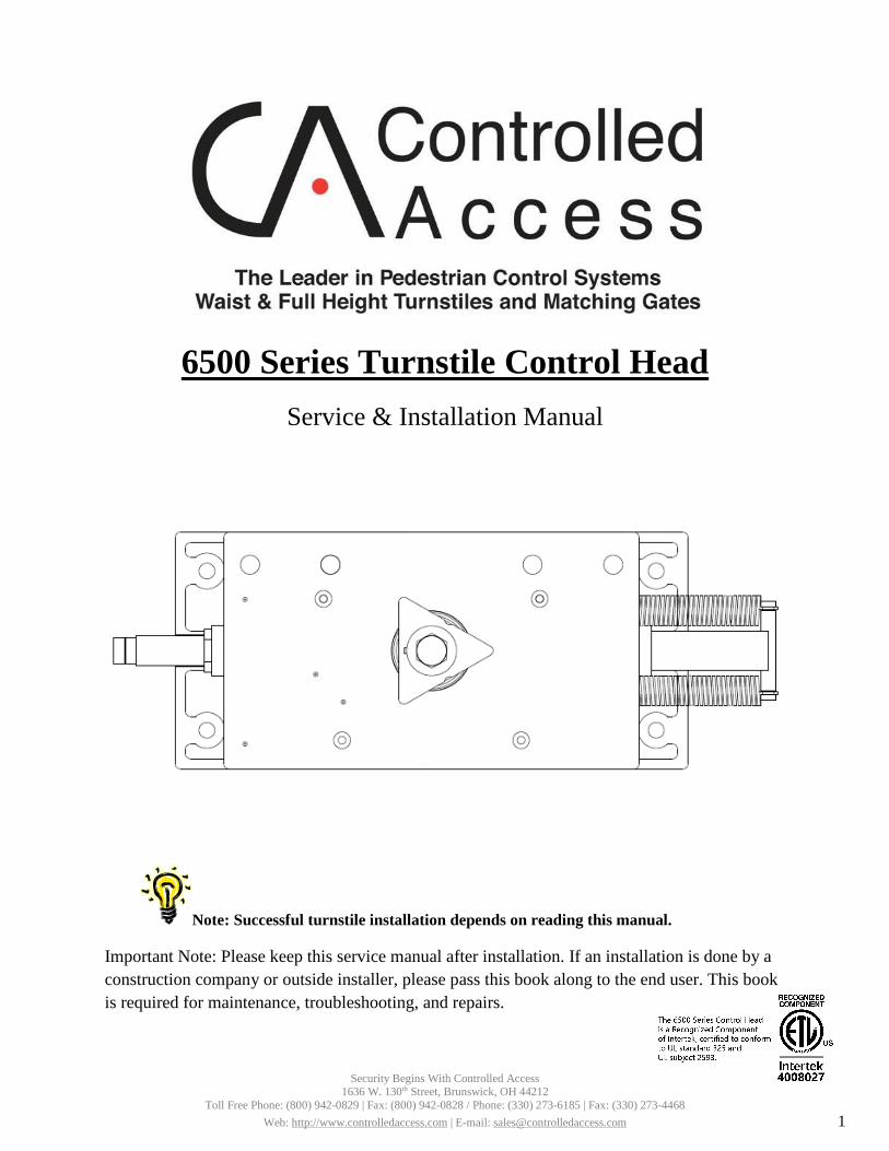
6500 Series Turnstile Control HeadService & Installation Manual
Note: Successful turnstile installation depends on reading this manual.
Important Note: Please keep this service manual after installation. If an installation is done by a construction company or outside installer, please pass this book along to the end user. This book is required for maintenance, troubleshooting, and repairs.
Security Begins With Controlled Access 1636 W. 130th Street, Brunswick, OH 44212
Toll Free Phone: (800) 942-0829 | Fax: (800) 942-0828 / Phone: (330) 273-6185 | Fax: (330) 273-4468 Web: http://www.controlledaccess.com | E-mail: [email protected] 1

Important Electrical Information Installation of the control head mechanism into the turnstile requires a grounding-type outlet receptacle installed inside of the frame or cabinet through the provided conduit access points.
To reduce the risk of electric shock, this equipment has a grounding type plug that has a third (grounding) pin. This plug will only fit into a grounding type outlet. If the plug does not fit into the outlet, contact a qualified electrician to install the proper outlet. Do not change this plug in any way.
Additionally, the MS2-H50 power supply from this appliance must be grounded to the frame of the turnstile. Utilize the green colored grounding screw threaded into the grounding tab located near the power supply along with the provided grounding wire from the power supply to ensure the equipment is proper grounded.
Security Begins With Controlled Access 1636 W. 130th Street, Brunswick, OH 44212
Toll Free Phone: (800) 942-0829 | Fax: (800) 942-0828 / Phone: (330) 273-6185 | Fax: (330) 273-4468 Web: http://www.controlledaccess.com | E-mail: [email protected] 2
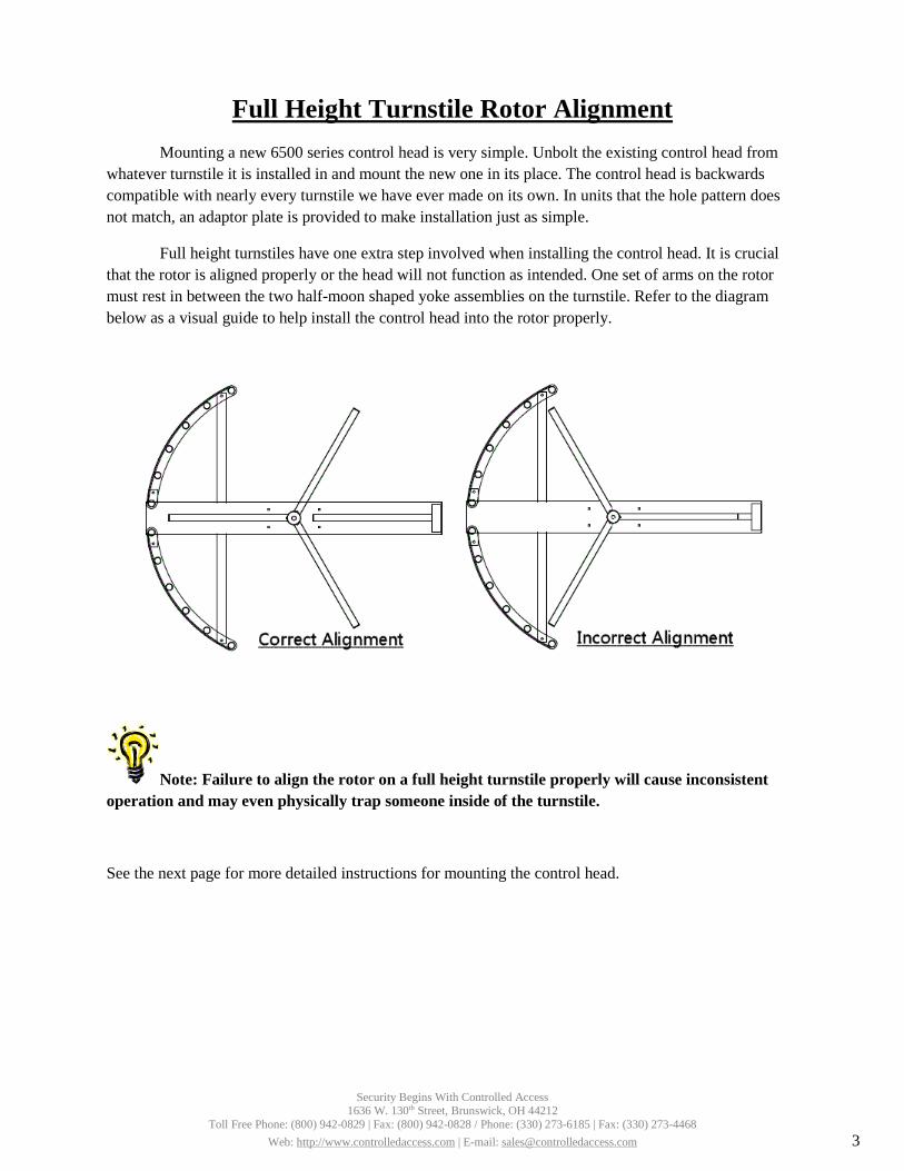
Full Height Turnstile Rotor Alignment Mounting a new 6500 series control head is very simple. Unbolt the existing control head from
whatever turnstile it is installed in and mount the new one in its place. The control head is backwards compatible with nearly every turnstile we have ever made on its own. In units that the hole pattern does not match, an adaptor plate is provided to make installation just as simple.
Full height turnstiles have one extra step involved when installing the control head. It is crucial that the rotor is aligned properly or the head will not function as intended. One set of arms on the rotor must rest in between the two half-moon shaped yoke assemblies on the turnstile. Refer to the diagram below as a visual guide to help install the control head into the rotor properly.
Note: Failure to align the rotor on a full height turnstile properly will cause inconsistent operation and may even physically trap someone inside of the turnstile.
See the next page for more detailed instructions for mounting the control head.
Security Begins With Controlled Access 1636 W. 130th Street, Brunswick, OH 44212
Toll Free Phone: (800) 942-0829 | Fax: (800) 942-0828 / Phone: (330) 273-6185 | Fax: (330) 273-4468 Web: http://www.controlledaccess.com | E-mail: [email protected] 3

6500 Series Control Head Installation
To reduce the risk of electrical shock, do NOT hard wire the power supply directly into input voltage. Only power this turnstile from a grounding-type receptacle. Should the turnstile be installed without a grounding-type receptacle, contact a qualified electrician to install one for you.
Waist High Installation:
New waist high turnstiles already have the 6500 series control head mounted in place.
However, should the need to replace the control head ever arise, follow these steps:
• Remove the arm assembly from the turnstile by unbolting the 3x 5/16 button head cap screws• Remove the lid from the cabinet. Some models have a lock and key system while some others are
secured with 10/24 button head screws located on the sides.• Unplug the control head from the grounded receptacle located inside of the cabinet.• Unbolt the 4x 5/16 carriage bolts holding the control head assembly in place.• Pull the control head out of the cabinet and disconnect any access control inputs from the control
board.• Place new control head on top of cabinet and connect access control inputs to the new control
board (see wiring diagram).• Insert control head into cabinet with the locking bars facing upwards toward you and bolt it into
place with 5/16 carriage bolts.• Ground the power supply to the cabinet.• Plug in the control head to the grounded outlet receptacle.• Install arm assembly onto arm adaptor with 5/16 button head cap screws.• Reinstall the lid.
Full Height Installation:
• Remove the cover from the mainframe by removing the 10/24 button head cap screws.• If replacing an existing control head follow these steps first:
o Unplug the existing control head from the grounded outlet receptacleo Unbolt the 4 3/8 carriage bolts holding the control head in placeo Disconnect access control inputs from existing control boardo Pull the existing control head out
• Install the control head into the hex insert on the rotor so that the rotor aligns with one set ofarms in between the two half-moon shaped yokes
• Bolt the control head into place• Connect access control inputs (see wiring diagram)• Ground the power supply to the frame utilizing the provided grounding tab located
near the control head.• Plug the control head into a grounded outlet receptacle.
Security Begins With Controlled Access 1636 W. 130th Street, Brunswick, OH 44212
Toll Free Phone: (800) 942-0829 | Fax: (800) 942-0828 / Phone: (330) 273-6185 | Fax: (330) 273-4468 Web: http://www.controlledaccess.com | E-mail: [email protected] 4
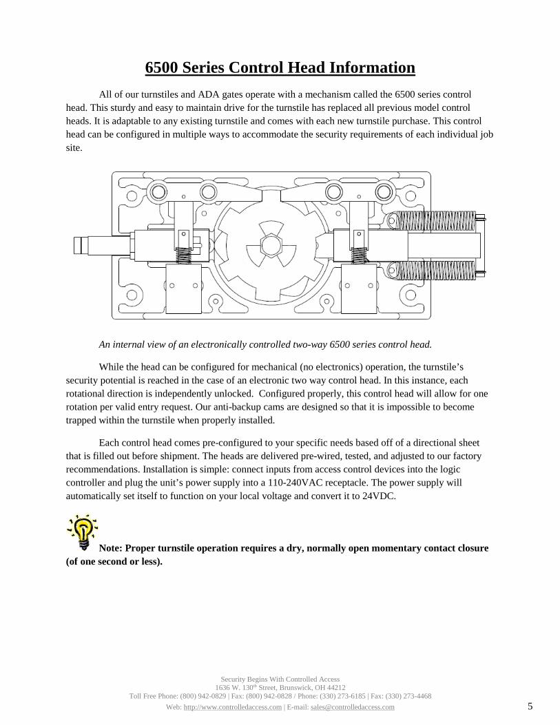
6500 Series Control Head InformationAll of our turnstiles and ADA gates operate with a mechanism called the 6500 series control
head. This sturdy and easy to maintain drive for the turnstile has replaced all previous model control heads. It is adaptable to any existing turnstile and comes with each new turnstile purchase. This control head can be configured in multiple ways to accommodate the security requirements of each individual job site.
An internal view of an electronically controlled two-way 6500 series control head.
While the head can be configured for mechanical (no electronics) operation, the turnstile’s security potential is reached in the case of an electronic two way control head. In this instance, each rotational direction is independently unlocked. Configured properly, this control head will allow for one rotation per valid entry request. Our anti-backup cams are designed so that it is impossible to become trapped within the turnstile when properly installed.
Each control head comes pre-configured to your specific needs based off of a directional sheet that is filled out before shipment. The heads are delivered pre-wired, tested, and adjusted to our factory recommendations. Installation is simple: connect inputs from access control devices into the logic controller and plug the unit’s power supply into a 110-240VAC receptacle. The power supply will automatically set itself to function on your local voltage and convert it to 24VDC.
Note: Proper turnstile operation requires a dry, normally open momentary contact closure (of one second or less).
Security Begins With Controlled Access 1636 W. 130th Street, Brunswick, OH 44212
Toll Free Phone: (800) 942-0829 | Fax: (800) 942-0828 / Phone: (330) 273-6185 | Fax: (330) 273-4468 Web: http://www.controlledaccess.com | E-mail: [email protected] 5
6500 Series Control Head Configuration Information The 6500 series can be configured in a number of different ways. All turnstiles operating with the 6500
series control head self center and hydraulically shock to the home position to prevent damage or injury.
Manual both ways: Turnstile rotates freely in both directions. This unsecure configuration is used as a means to direct traffic through one area. Full height turnstiles can be purchased with a lockout bar which would allow end user to lock the turnstile with a standard pad lock.
Manual one way: Turnstile rotates in one direction but not the other. This configuration is great for an exit way.
Electronic one way with free exit: Turnstile rotates freely in one direction and requires access credentials for the other. This configuration is suitable for secure entry and unsecure exit.
Electronic one way with no exit: Turnstile requires access credentials for one direction and allows no passage in the other. This configuration is suitable for a secured entryway with an alternate means of exit.
Electronic two way: Turnstile requires access credentials for both directions. This configuration is perfect for locations requiring secured entry and exit passage.
Fail lock: Upon power failure, turnstile will remain locked in one or both directions. This is convertible to fail open by ordering an alternate linkage. This can also be known as fail secure.
Fail open: Upon power failure, turnstile will remain unlocked in one or both directions. This is convertible to fail lock by ordering an alternate linkage. This can also be known as fail safe.
Key override: This option is for a location that the security requirements may change. The key override option is not intended for everyday use. Should you require an additional lockdown feature on your turnstile, a better option is a lockout bar (Figure L) with a standard pad lock.
Figure L: Optional lockout bar
Security Begins With Controlled Access 1636 W. 130th Street, Brunswick, OH 44212
Toll Free Phone: (800) 942-0829 | Fax: (800) 942-0828 / Phone: (330) 273-6185 | Fax: (330) 273-4468 Web: http://www.controlledaccess.com | E-mail: [email protected]
8
6500 Series Control Head Locking Bar Information Any number of configurations is possible on the 6500 series control head. In the case of an electronic
two way head, two independent locking mechanisms are in place. The following diagram indicates which direction unlocks from which locking mechanism. A logic controller or key override is needed to unlock the control head in each direction it is configured to lock in.
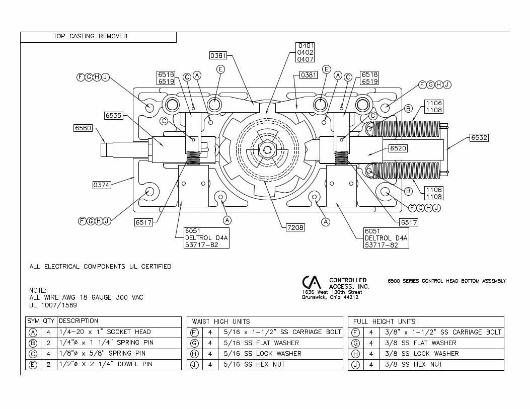
If removing the locking bar becomes necessary for any reason, two methods can be used. The easiest method is to punch the ½” dowel pin out from the bottom side of the control head. This releases the locking bar from the casting. An alternate approach would be to remove the (4) ¼-20 socket head cap screws from the casting and remove the lid.
When installing or replacing the locking bars into the control head, be sure to take special care to align the solenoid spring (shown below) or it will not pivot properly.
Security Begins With Controlled Access 1636 W. 130th Street, Brunswick, OH 44212
Toll Free Phone: (800) 942-0829 | Fax: (800) 942-0828 / Phone: (330) 273-6185 | Fax: (330) 273-4468 Web: http://www.controlledaccess.com | E-mail: [email protected]
9
Power Failure State Configuration (Fail Lock / Fail Open) Each direction on a control head can be independently configured to open or lock upon power failure.
The fail status configuration is based on the pivot point used on the locking bar as well as the linkage and solenoid spring used. Control heads are preconfigured in our factory before shipment based on a direction sheet filled out by the end user. In the event a fail status field change is needed, a different linkage and spring will be required (the part numbers are noted in a table below). Control heads can also be returned to the factory for reconfiguration for a fee of parts plus approximately 1 hour of labor if desired.
Description Part Number
Fail lock linkage 6518
Fail open linkage 6519
Fail open solenoid spring 6510
Fail lock solenoid spring 6016
Note: As a reference, it may be important to know that some vendors use different terms for fail status. Fail open is also known as fail safe, while fail lock is also known as fail secure.
Security Begins With Controlled Access 1636 W. 130th Street, Brunswick, OH 44212
Toll Free Phone: (800) 942-0829 | Fax: (800) 942-0828 / Phone: (330) 273-6185 | Fax: (330) 273-4468 Web: http://www.controlledaccess.com | E-mail: [email protected]
10
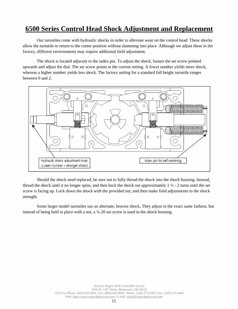
6500 Series Control Head Shock Adjustment and Replacement Our turnstiles come with hydraulic shocks in order to alleviate wear on the control head. These shocks
allow the turnstile to return to the center position without slamming into place. Although we adjust these in the factory, different environments may require additional field adjustment.
The shock is located adjacent to the index pin. To adjust the shock, loosen the set screw pointed upwards and adjust the dial. The set screw points at the current setting. A lower number yields more shock, whereas a higher number yields less shock. The factory setting for a standard full height turnstile ranges between 0 and 2.
Should the shock need replaced, be sure not to fully thread the shock into the shock housing. Instead, thread the shock until it no longer spins, and then back the shock out approximately 1 ½ - 2 turns until the set screw is facing up. Lock down the shock with the provided nut, and then make field adjustments to the shock strength.
Some larger model turnstiles use an alternate, heavier shock. They adjust in the exact same fashion, but instead of being held in place with a nut, a ¼-20 set screw is used in the shock housing.
Security Begins With Controlled Access 1636 W. 130th Street, Brunswick, OH 44212
Toll Free Phone: (800) 942-0829 | Fax: (800) 942-0828 / Phone: (330) 273-6185 | Fax: (330) 273-4468 Web: http://www.controlledaccess.com | E-mail: [email protected]
11
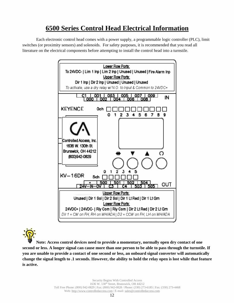
6500 Series Control Head Electrical Information Each electronic control head comes with a power supply, a programmable logic controller (PLC), limit
switches (or proximity sensors) and solenoids. For safety purposes, it is recommended that you read all literature on the electrical components before attempting to install the control head into a turnstile.
Note: Access control devices need to provide a momentary, normally open dry contact of one second or less. A longer signal can cause more than one person to be able to pass through the turnstile. If you are unable to provide a contact of one second or less, an onboard signal converter will automatically change the signal length to .1 seconds. However, the ability to hold the relay open is lost while that feature is active.
Security Begins With Controlled Access 1636 W. 130th Street, Brunswick, OH 44212
Toll Free Phone: (800) 942-0829 | Fax: (800) 942-0828 / Phone: (330) 273-6185 | Fax: (330) 273-4468 Web: http://www.controlledaccess.com | E-mail: [email protected]
12
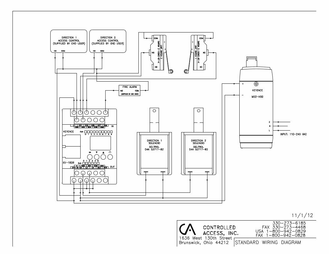

6500 Series Control Head Wiring Legend Since each control head comes pre-wired, only access control and fire alarm should need to be connected to the board. If you are unable to fit wires for access control on the 24VDC+ input on the board, the voltage can be picked up directly from the power supply or from the relay commons (C3 & C4) on the board (C4 may not have voltage depending on options purchased. There will be a red jumper to C4 if there is). You may also run a jumper from 24VDC+ to any unused input to give additional contacts if needed.
Note: Directional status outputs are unaffected by optional key overrides as the override occurs outside of the logic controller.
Security Begins With Controlled Access 1636 W. 130th Street, Brunswick, OH 44212
Toll Free Phone: (800) 942-0829 | Fax: (800) 942-0828 / Phone: (330) 273-6185 | Fax: (330) 273-4468 Web: http://www.controlledaccess.com | E-mail: [email protected]
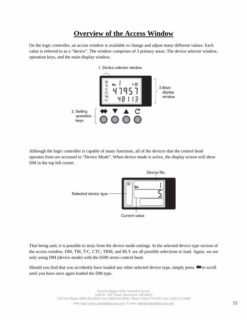
Overview of the Access Window On the logic controller, an access window is available to change and adjust many different values. Each value is referred to as a “device”. The window comprises of 3 primary areas: The device selector window, operation keys, and the main display window.
Although the logic controller is capable of many functions, all of the devices that the control head operates from are accessed in “Device Mode”. When device mode is active, the display screen will show DM in the top left corner.
That being said, it is possible to stray from the device mode settings. In the selected device type section of the access window, DM, TM, T/C, CTC, TRM, and RLY are all possible selections to load. Again, we are only using DM (device mode) with the 6500 series control head.
Should you find that you accidently have loaded any other selected device type, simply press to scroll until you have once again loaded the DM type.
Security Begins With Controlled Access 1636 W. 130th Street, Brunswick, OH 44212
Toll Free Phone: (800) 942-0829 | Fax: (800) 942-0828 / Phone: (330) 273-6185 | Fax: (330) 273-4468 Web: http://www.controlledaccess.com | E-mail: [email protected] 15

In addition to the device mode window, system mode can be accessed as well.
Although under normal circumstances you should never encounter this window, if by accident you should happen to come across it, simply press the up or down arrow until the window reads “run”. Press and hold the button for 3 seconds, and the display will return to device mode.
Additionally, should for any reason the display lettering become red instead of green, you will need to access system mode to run the program in this fashion. Holding the key while pressing up and down allows you to change between system mode and device mode. A third mode, which will display TRM on the left side of the screen, can also be accessed. Cycle through until the appropriate mode is displayed.
Finally, it is possible to lock the keypad. Should you inadvertently do so, press and hold the button and an arrow key together for 3 seconds to unlock the keypad again.
Security Begins With Controlled Access 1636 W. 130th Street, Brunswick, OH 44212
Toll Free Phone: (800) 942-0829 | Fax: (800) 942-0828 / Phone: (330) 273-6185 | Fax: (330) 273-4468 Web: http://www.controlledaccess.com | E-mail: [email protected] 16
Device Settings of the 6500 Series Control Head While working within device mode, two primary values should be considered. On the top of the display, the selected device is shown. The 6500 series control head settings can be adjusted with devices 0 – 7.
Pressing the up or down arrows allow you to select which device you wish to modify. Pressing and holding the key for 3 seconds loads the modification window. While modifying, the digits on the window begin to flash. Pressing will move the cursor in a digit. Select the correct digit to modify, then use the arrows to change the value. Once finished, hold the button for 3 seconds and your adjustment will save.
Should a value inputted not fall within the specified range of the device being modified, the value will automatically adjust to the highest possible value. A description of each device setting is:
• DM0: Timer value for Direction 1. The range of this setting is 1 – 60 seconds. This is how longthe direction will remain open for if a user does not pass through the direction. The default settingis 7 seconds.
• DM1: Timer value for Direction 2. The range of this setting is 1 – 60 seconds. This is how longthe direction will remain open for if a user does not pass through the direction. The default settingis 7 seconds.
• DM2: Direction 1 fail status. This determines when the solenoid receives power and ispreconfigured based on each individual order. 0 means the direction is fail lock & 1 means thedirection is fail open. This setting is not affected by factory reset.
• DM3: Direction 2 fail status. This determines when the solenoid receives power and ispreconfigured based on each individual order. 0 means the direction is fail lock & 1 means thedirection is fail open. This setting is not affected by factory reset.
• DM4: Direction 1 one-shot timer: This setting determines whether or not the access control inputlength is ignored and converted to a .1 second pulse internally. Enabling this allows the turnstileto ignore access control from allowing too many users pass through the turnstile. Disabling itallows access control to hold the direction open. 0 means the one-shot timer is inactive & 1 meansthe one-shot timer is active.
• DM5: Direction 2 one-shot timer: This setting determines whether or not the access control inputlength is ignored and converted to a .1 second pulse internally. Enabling this allows the turnstileto ignore access control from allowing too many users pass through the turnstile. Disabling itallows access control to hold the direction open. 0 means the one-shot timer is inactive & 1 meansthe one-shot timer is active.
• DM6: Direction 1 multi-swipe: This setting allows more than one access control request to beprocessed at a time to allow a faster flow of traffic. The range is 1-3. As each access controlrequest is processed, each rotation subtracts from the total, allowing a constant flow of traffic.Most installations would benefit from a value of 2, which is the default setting.
• DM7: Direction 2 multi-swipe: This setting allows more than one access control request to beprocessed at a time to allow a faster flow of traffic. The range is 1-3. As each access controlrequest is processed, each rotation subtracts from the total, allowing a constant flow of traffic.Most installations would benefit from a value of 2, which is the default setting.
Security Begins With Controlled Access 1636 W. 130th Street, Brunswick, OH 44212
Toll Free Phone: (800) 942-0829 | Fax: (800) 942-0828 / Phone: (330) 273-6185 | Fax: (330) 273-4468 Web: http://www.controlledaccess.com | E-mail: [email protected] 17

• DM9: Direction 1 Count: Displays how many valid rotations were made in direction 1. This has amax value of 60,000 and will reset to 0 once that number is reached. This will not count firealarm, hold open or key override rotations. This count is for maintainence and repair loggingpurposes.
• DM10: Direction 2 Count: Displays how many valid rotations were made in direction 2. This hasa max value of 60,000 and will reset to 0 once that number is reached. This will not count firealarm, hold open or key override rotations. This count is for maintainence and repair loggingpurposes.
Additionally, scrolling downward past DM0 will allow you access to DM1999, which resets all settings to factory defaults (except for solenoid fail status settings). Choose any value greater than 0 to perform the factory reset.
Security Begins With Controlled Access 1636 W. 130th Street, Brunswick, OH 44212
Toll Free Phone: (800) 942-0829 | Fax: (800) 942-0828 / Phone: (330) 273-6185 | Fax: (330) 273-4468 Web: http://www.controlledaccess.com | E-mail: [email protected] 18
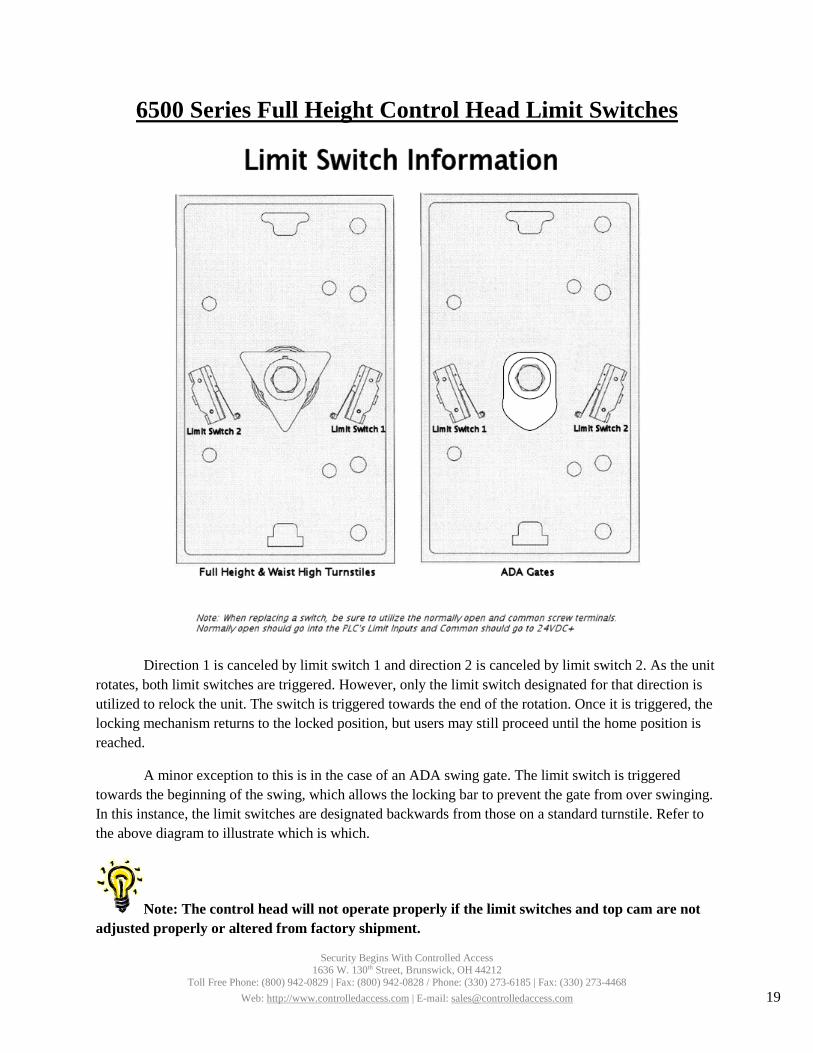
6500 Series Full Height Control Head Limit Switches
Direction 1 is canceled by limit switch 1 and direction 2 is canceled by limit switch 2. As the unit rotates, both limit switches are triggered. However, only the limit switch designated for that direction is utilized to relock the unit. The switch is triggered towards the end of the rotation. Once it is triggered, the locking mechanism returns to the locked position, but users may still proceed until the home position is reached.
A minor exception to this is in the case of an ADA swing gate. The limit switch is triggered towards the beginning of the swing, which allows the locking bar to prevent the gate from over swinging. In this instance, the limit switches are designated backwards from those on a standard turnstile. Refer to the above diagram to illustrate which is which.
Note: The control head will not operate properly if the limit switches and top cam are not adjusted properly or altered from factory shipment.
Security Begins With Controlled Access 1636 W. 130th Street, Brunswick, OH 44212
Toll Free Phone: (800) 942-0829 | Fax: (800) 942-0828 / Phone: (330) 273-6185 | Fax: (330) 273-4468 Web: http://www.controlledaccess.com | E-mail: [email protected] 19

6500 Series Control Head & Turnstile Maintenance & Cleaning
To ensure long life on any turnstile, the following maintenance is recommended.
• Annualo If you have a full height turnstile: On the bottom of each rotor, you should find a grease
fitting. Utilize this fitting to re-grease the bearing that the rotor rests on.o Make sure all nuts are securely fastened on all parts of the turnstile.o On the control head, remove the index pin and apply white lithium grease. Use 3 in 1 oil
on the index pin roller. The index pin is easily removed from the control head bydisconnecting the springs from it.
• Bi-annualo Remove the lid from the control head. Clean any debris and apply grease to the shock
roller assembly. Use 3 in 1 oil on the shock piston roller.o Apply 3 in 1 oil to the bronze bushing on the locking bars.o Inspect control head parts for wear and tear, replace parts as needed.o Reassemble control head. Using a removable strength (blue) thread sealer (such as
Loctite 242 or 243) on the head bolts will help the control head remain sturdy.• Cleaning
o Galvanized turnstiles can be cleaned with soap and water. Galvanized finish may fade incolor over time, but this is normal.
o Powder coated turnstiles should be cleaned with a non-abrasive cleanser such as Formula409. Be sure to inspect for chips on the powder coating and touch them up, or theexposed steel may rust.
o Stainless steel turnstiles should be polished with a stainless steel wax or polish. In harshenvironments, such as facilities near the ocean or within a chemical plant, stainlesssteel turnstiles should be waxed with a simple car wax to prevent surfacediscoloration on an annual basis. Discoloration and surface rust can be easily removedwith a rust penetrating product, such as P.B. Blaster, along with non-scratching scouringpads.
Control heads can be removed from the turnstile and shipped to the factory at any time for repairs and maintenance. Please include contact information so we can call to discuss any issues your control head may have. Please note that any repairs that cost under $500.00 will require a credit card payment.
Note: The recommended time frames are assuming a maximum of 75000 passages per year. Turnstiles with heavier traffic should be maintained more frequently.
Security Begins With Controlled Access 1636 W. 130th Street, Brunswick, OH 44212
Toll Free Phone: (800) 942-0829 | Fax: (800) 942-0828 / Phone: (330) 273-6185 | Fax: (330) 273-4468 Web: http://www.controlledaccess.com | E-mail: [email protected] 20
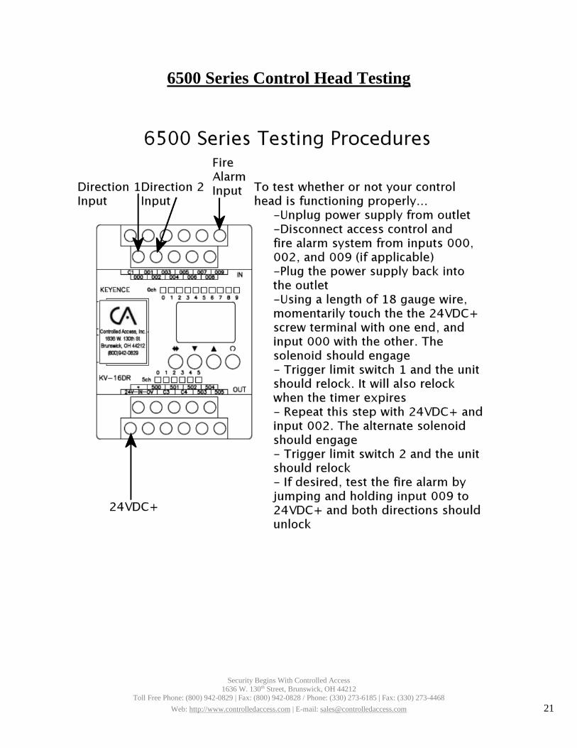
6500 Series Control Head Testing
Security Begins With Controlled Access 1636 W. 130th Street, Brunswick, OH 44212
Toll Free Phone: (800) 942-0829 | Fax: (800) 942-0828 / Phone: (330) 273-6185 | Fax: (330) 273-4468 Web: http://www.controlledaccess.com | E-mail: [email protected] 21
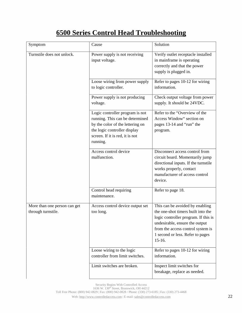
6500 Series Control Head Troubleshooting Symptom Cause Solution
Turnstile does not unlock. Power supply is not receiving input voltage.
Verify outlet receptacle installed in mainframe is operating correctly and that the power supply is plugged in.
Loose wiring from power supply to logic controller.
Refer to pages 10-12 for wiring information.
Power supply is not producing voltage.
Check output voltage from power supply. It should be 24VDC.
Logic controller program is not running. This can be determined by the color of the lettering on the logic controller display screen. If it is red, it is not running.
Refer to the “Overview of the Access Window“ section on pages 13-14 and “run” the program.
Access control device malfunction.
Disconnect access control from circuit board. Momentarily jump directional inputs. If the turnstile works properly, contact manufacturer of access control device.
Control head requiring maintenance.
Refer to page 18.
More than one person can get through turnstile.
Access control device output set too long.
This can be avoided by enabling the one-shot timers built into the logic controller program. If this is undesirable, ensure the output from the access control system is 1 second or less. Refer to pages 15-16.
Loose wiring to the logic controller from limit switches.
Refer to pages 10-12 for wiring information.
Limit switches are broken. Inspect limit switches for breakage, replace as needed.
Security Begins With Controlled Access 1636 W. 130th Street, Brunswick, OH 44212
Toll Free Phone: (800) 942-0829 | Fax: (800) 942-0828 / Phone: (330) 273-6185 | Fax: (330) 273-4468 Web: http://www.controlledaccess.com | E-mail: [email protected] 22
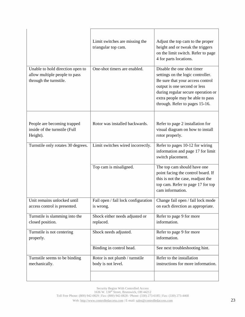
Limit switches are missing the triangular top cam.
Adjust the top cam to the proper height and or tweak the triggers on the limit switch. Refer to page 4 for parts locations.
Unable to hold direction open to allow multiple people to pass through the turnstile.
One-shot timers are enabled. Disable the one shot timer settings on the logic controller. Be sure that your access control output is one second or less during regular secure operation or extra people may be able to pass through. Refer to pages 15-16.
People are becoming trapped inside of the turnstile (Full Height).
Rotor was installed backwards. Refer to page 2 installation for visual diagram on how to install rotor properly.
Turnstile only rotates 30 degrees. Limit switches wired incorrectly. Refer to pages 10-12 for wiring information and page 17 for limit switch placement.
Top cam is misaligned. The top cam should have one point facing the control board. If this is not the case, readjust the top cam. Refer to page 17 for top cam information.
Unit remains unlocked until access control is presented.
Fail open / fail lock configuration is wrong.
Change fail open / fail lock mode on each direction as appropriate.
Turnstile is slamming into the closed position.
Shock either needs adjusted or replaced.
Refer to page 9 for more information.
Turnstile is not centering properly.
Shock needs adjusted. Refer to page 9 for more information.
Binding in control head. See next troubleshooting hint.
Turnstile seems to be binding mechanically.
Rotor is not plumb / turnstile body is not level.
Refer to the installation instructions for more information.
Security Begins With Controlled Access 1636 W. 130th Street, Brunswick, OH 44212
Toll Free Phone: (800) 942-0829 | Fax: (800) 942-0828 / Phone: (330) 273-6185 | Fax: (330) 273-4468 Web: http://www.controlledaccess.com | E-mail: [email protected] 23

Control head requires maintenance.
Refer to page 27 for more information.
Turnstile rotating the wrong direction.
Improperly filled out direction sheet.
In some cases, the control head can be reconfigured in the field to operate as needed. Refer to pages 7-8 for information about how the control head operates. If needed, control heads can be returned to the factory for reconfiguration for a fee of labor plus parts (if required). Please contact us before returning a control head in this instance.
Directional inputs wired incorrectly.
Refer to wiring legend for direction port explanations
Turnstile fails lock when needed to fail open or vice versa.
Improperly filled out direction sheet.
Refer to page 8 for more information. Additional parts will be required to convert operation. The control head can be returned for reconfiguration for a fee of labor plus parts (if required). Please contact us before returning a control head in this instance.
Other problems. Please contact us for any other issues.
Security Begins With Controlled Access 1636 W. 130th Street, Brunswick, OH 44212
Toll Free Phone: (800) 942-0829 | Fax: (800) 942-0828 / Phone: (330) 273-6185 | Fax: (330) 273-4468 Web: http://www.controlledaccess.com | E-mail: [email protected] 24

Proper Turnstile Usage The 6500 series turnstile control head is easy to use. There are a few things that users should be
trained on and informed of.
• In the case of an electronic turnstile, approach the unit and swipe the card. Do not push on thearms of the rotor until after access control device is engaged and a click sound from themainframe is heard. This sound is the locking mechanism engaging.
Note: Turnstile will not unlock if pressure is being applied to the rotor. The unit will unlock after pressure is released; however, it is a better practice to wait until the click sound is heard before pushing the rotor.
• After requesting access with access control devices, proceed through turnstile immediately.Waiting too long could cause the turnstile to time-out mid rotation, forcing the user to back out of the turnstile. Factory timer settings are at 7 seconds. While these timers are adjustable for up to 60 seconds, we recommend 7-10 seconds because if someone chooses to swipe and walk away from the turnstile, another person would not be able to pass through without credentials. The limit switches on the control head override the directional timers.
• Walk at a reasonable pace through the turnstile. Do not slam the rotor through the rotation. Thiscan be unsafe and may cause unnecessary wear and tear to the control head.
• Try to be respectful of users wanting to pass through the other direction. Allow people who arewaiting an opportunity to pass through the turnstile.
• Avoid rotating the rotor on a full height before walking through on a valid entry request. This willcause the rotor to lock before you have a chance to pass through the turnstile.
• Piggybacking: More than one user trying to squeeze through the turnstile on one rotation shouldbe avoided. Large bags and carts should be brought through an alternate means of entrance.
Security Begins With Controlled Access 1636 W. 130th Street, Brunswick, OH 44212
Toll Free Phone: (800) 942-0829 | Fax: (800) 942-0828 / Phone: (330) 273-6185 | Fax: (330) 273-4468 Web: http://www.controlledaccess.com | E-mail: [email protected] 25
1
Part Names and Functions
Safety Precautions
• Do not perform any electrical wiring while electric current is applied. Failureto follow this may result in an electric shock or fire.
• Be sure to connect the grounding cable. Failure to follow this may resultin an electric shock or fire.
• Do not touch this unit within 1 minute after AC input is turned off. Failureto follow this may result in an electric shock.
• Do not modify or repair this unit. Failure to follow this may result in anelectric shock, accident, or product failure.
• Do not touch any terminal of this unit while electric current is applied.Use the unit with the terminal cover installed to avoid an electric shock.
• When this unit is used in a system that may cause a serious accident ordamage if the unit fails, be sure to install a safety device.
• Pay attention to prevent foreign matter such as metal particles, dust,paper or wood chips from entering the inside of this unit. Failure tofollow this may result in a fire or product failure.
• Do not touch any metallic part while electric current is applied orimmediately after input is shut off. Failure to follow this may result in aburn due to a high temperature.
• If a failure or abnormality occurs while this unit is in use, immediatelysuch off AC input and stop operation of this unit . Failure to follow thismay result in a fire or accident.
• Check that the AC input rated voltage of this unit is equal to the voltageof the AC power supply.
• Do not connect the AC power supply to the DC output terminals.• Do not disturb the convection of air near the vent of the casing.
Precautions for CE MarkingsKEYENCE has evaluated the conformity of the MS2 Series with the requirements of the EMCDirectives and Low-voltage Directives under the following condition, and confirmed that the MS2Series meets these requirements. For the Low-voltage Directives, the MS2 Series has obtainedcertification from TUV Rheinland for the following standards.<Precautions> EMC Directives (89/336/EEC)• Applicable standard (EMI) EN55011, Group 1, Class A• Applicable standard (EMS) EN61000-6-2 Low-voltage Directives (73/23/EEC) • Applicable standard EN60950-1
EN50178 • Overvoltage category II • Pollution degree 2
• The MS2 Series is designed as a Class I Equipment. Be sure to connect the protective earthingterminal on the terminal block to the protective earthing conductor in the building installation.
• The MS2 Series is an open-type device. Be sure to install it in an appropriate enclosure rated asIP54 or better.
• Use the MS2 Series according to the derating conditions and the installation conditions described inthis manual.
• The MS2 Series does not include a disconnecting device. Be sure to install a disconnecting devicesuch as a circuit breaker in the building installation wiring.
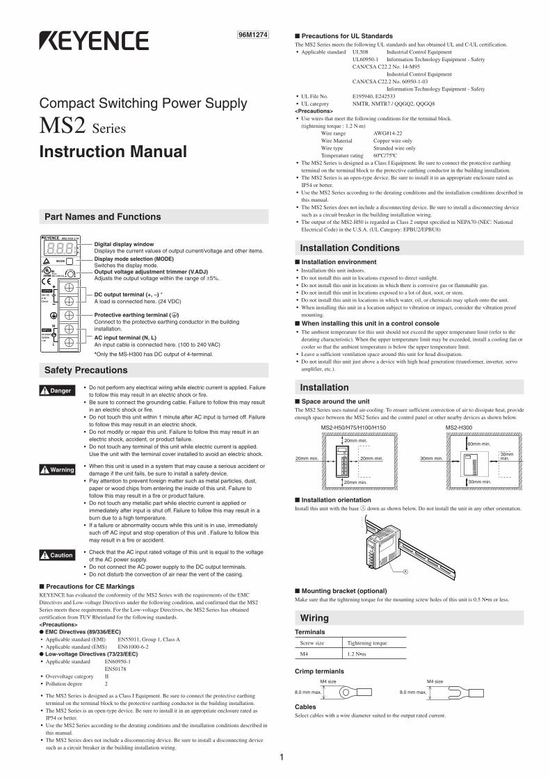
.8.8.8Display mode selection (MODE)Switches the display mode.
AC input terminal (N, L)An input cable is connected here. (100 to 240 VAC)
Protective earthing terminal ( )Connect to the protective earthing conductor in the buildinginstallation.
Digital display windowDisplays the current values of output current/voltage and other items.
DC output terminal (+, –) *A load is connected here. (24 VDC)
Output voltage adjustment trimmer (V.ADJ)Adjusts the output voltage within the range of ±5%.
Compact Switching Power Supply
MS2 Series
Instruction Manual
Precautions for UL StandardsThe MS2 Series meets the following UL standards and has obtained UL and C-UL certification. • Applicable standard UL508 Industrial Control Equipment
UL60950-1 Information Technology Equipment - SafetyCAN/CSA C22.2 No. 14-M95
Industrial Control EquipmentCAN/CSA C22.2 No. 60950-1-03
Information Technology Equipment - Safety • UL File No. E195940, E242533 • UL category NMTR, NMTR7 / QQGQ2, QQGQ8<Precautions> • Use wires that meet the following conditions for the terminal block.
(tightening torque : 1.2 N·m)Wire range AWG#14-22Wire Material Copper wire onlyWire type Stranded wire onlyTemperature rating 60ºC/75ºC
• The MS2 Series is designed as a Class I Equipment. Be sure to connect the protective earthingterminal on the terminal block to the protective earthing conductor in the building installation.
• The MS2 Series is an open-type device. Be sure to install it in an appropriate enclosure rated asIP54 or better.
• Use the MS2 Series according to the derating conditions and the installation conditions described inthis manual.
• The MS2 Series does not include a disconnecting device. Be sure to install a disconnecting devicesuch as a circuit breaker in the building installation wiring.
• The output of the MS2-H50 is regarded as Class 2 output specified in NEPA70 (NEC: NationalElectrical Code) in the U.S.A. (UL Category: EPBU2/EPBU8)
Installation Conditions Installation environment • Installation this unit indoors. • Do not install this unit in locations exposed to direct sunlight. • Do not install this unit in locations in which there is corrosive gas or flammable gas. • Do not install this unit in locations exposed to a lot of dust, soot, or stem. • Do not install this unit in locations in which water, oil, or chemicals may splash onto the unit. • When installing this unit in a location subject to vibration or impact, consider the vibration proof
mounting.
When installing this unit in a control console • The ambient temperature for this unit should not exceed the upper temperature limit (refer to the
derating characteristic). When the upper temperature limit may be exceeded, install a cooling fan orcooler so that the ambient temperature is below the upper temperature limit.
• Leave a sufficient ventilation space around this unit for head dissipation. • Do not install this unit just above a device with high head generation (transformer, inverter, servo
amplifier, etc.).
Installation Space around the unitThe MS2 Series uses natural air-cooling. To ensure sufficient convection of air to dissipate heat, provideenough space between the MS2 Series and the control panel or other nearby devices as shown below.
Installation orientationInstall this unit with the base A down as shown below. Do not install the unit in any other orientation.
Mounting bracket (optional)Make sure that the tightening torque for the mounting screw holes of this unit is 0.5 N•m or less.
WiringTerminals
Screw size Tightening torque
M4 1.2 N•m
Crimp termianls
CablesSelect cables with a wire diameter suited to the output rated current.
96M1274
8.0 mm max. 8.0 mm max.
M4 size M4 size
20mm min.
20mm min.
20mm min. 20mm min.
Danger
Warning
Caution
*Only the MS-H300 has DC output of 4-terminal.
MS2-H50/H75/H100/H150
60mm min.
30mm min.
30mm min.30mm min.
MS2-H300
2
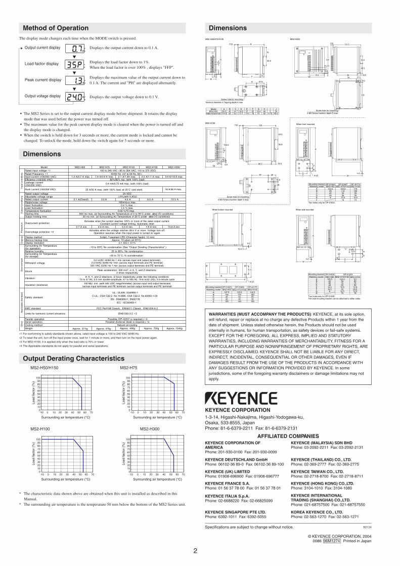
Method of OperationThe display mode changes each time when the MODE switch is pressed.
Output current display
Load factor display °
Peak current display
Output voltage display
• The MS2 Series is set to the output current display mode before shipment. It retains the displaymode that was used before the power was turned off.
• The maximum value for the peak current display mode is cleared when the power is turned off andthe display mode is changed.
• When the switch is held down for 3 seconds or more, the current mode is locked and cannot bechanged. To unlock the mode, hold down the switch again for 3 seconds or more.
Dimensions
Displays the output current down to 0.1 A.
Displays the load factor down to 1%.When the load factor is over 100% , displays "FFP".
Displays the maximum value of the output current down to0.1 A. The current and "PH" are displayed alternately.
Displays the output voltage down to 0.1 V.
WARRANTIES (MUST ACCOMPANY THE PRODUCTS): KEYENCE, at its sole option,will refund, repair or replace at no charge any defective Products within 1 year from thedate of shipment. Unless stated otherwise herein, the Products should not be usedinternally in humans, for human transportation, as safety devices or fail-safe systems.EXCEPT FOR THE FOREGOING, ALL EXPRESS, IMPLIED AND STATUTORYWARRANTIES, INCLUDING WARRANTIES OF MERCHANTABILITY, FITNESS FOR APARTICULAR PURPOSE AND NONINFRINGEMENT OF PROPRIETARY RIGHTS, AREEXPRESSLY DISCLAIMED. KEYENCE SHALL NOT BE LIABLE FOR ANY DIRECT,INDIRECT, INCIDENTAL, CONSEQUENTIAL OR OTHER DAMAGES, EVEN IFDAMAGES RESULT FROM THE USE OF THE PRODUCTS IN ACCORDANCE WITHANY SUGGESTIONS OR INFORMATION PROVIDED BY KEYENCE. In somejurisdictions, some of the foregoing warranty disclaimers or damage limitations may notapply.
Two holes only for OP-51624.
Two holes only for OP-51626.The side mounting bracket can be attached to either sides.
MS2-H150 When front mounted
When side mounted
F 15 1512.512.58E
1701225954
112159.5
4599
123.5
CBA
MS2-H150OP-42174
MS2-H75/H100OP-51627
MS2-H50OP-51624
Matching modelMounting bracket
D 20 30 40
MS2-H300MS2-H50/H75/H100
B
D
10
C
3
A
15F
(12) E
J
H 27.5 I
Nominal diameter 3 Tapping depth 4 max.
Screw hole for mounting
10
14.3
122.5
2.516.1
(12) 120
85.5 16.5
60 28
28
15.5
4-M3 Screw insertion depth 5 max.Screw hole for mounting
D
A
E
F
Bt=2
C
G
H
FCDE
A
Bt=2
When bottom mounted
BE
CD
A
t=2
12.5
4-φ5
4-φ5
15 15H12.512.58G
65
F 14.5 16 20.512.512.512.5E
45120.5
CBA
MS2-H150MS2-H75/H100OP-51623
MS2-H50OP-51626
Matching modelMounting bracket
7560157
7554
153.5
D 40 50 50
132.51605554
150122.5
45135
107.5
CBA
MS2-H50OP-42175
MS2-H75/H100OP-51628
MS2-H150OP-51625
Matching modelMounting bracket
D 20 30 40E 125 140 150
Model A99.5
114.5
B4052
C14.715.1
D14.617.1
E97
110
F6578
G33.441
H4052
I5
4.75
J30
42.5MS2-H50
MS2-H75/H100
G
35.9
59
43.3
35.9
75
4-M3 Screw insertion depth 5 max.Screw hole for mounting
78 21.5
120
10
35.9
46.5
96 16.5
131.5
70.5140
2
16.8
124
(10)
P=10
Input current (100/200 VAC) 1.3 A/0.7 A max. 1.9 A/0.9 A max. 2.1 A/1.3A max. 2.2 3.9 A/1.8 A max.
18 A/36 A max.
A/1.1 A max.Efficiency (100/200 VAC)Leakage current(100/200 VAC)
Starting timeOutput holding time
2.7 A min. 4.0 A min. 5.3 A min. 7.9 15.6 A minA min.
Display methodMemory backup timeDisplay resolutionSurrounding Air Temperature(for operation)
Surrounding Air Temperature(for storage)
Safety standard
Limits for harmonic current emissions
Approx. 27 0g Approx. 470g Approx. 490g Approx. 700gNatural air-cooling
Possible (OP-42207 is required.) ∗4Possible (External diode is required.) ∗4
EN61000-3-2 ∗3
FCC Part15B ClassA, EN55011 ClassA, EN61000-6-2
UL : UL508, UL60950-1C-UL : CSA C22.2 No.14-M95, CSA C22.2 No.60950-1-03
EN : EN60950-1, EN50178IEC : IEC60950-1
100 to 240 VAC ( 85 to 264 VAC, 110 to 370 VDC)Model
3-digit, 7-segment LED (Character height: 10 mm)Approx. 10 years (at 20°C)
50/60 Hz (47 to 63 Hz, DC )
82%/85% typ. (with 100% load)
25 A/50 A max. (with 100% load, at 25°C cold start)
24 VDC
180mVp-p max.
MS2-H50 MS2-H75 MS2-H100 MS2-H150 MS2-H300Rated Input voltage ∗1Rated Frequency ∗1
Rush current (100/200 VAC)
Rated output voltageAdjustable voltage rangeRated output current 2.1 A(Class2) 3.2 A 4.5 A 12.5 A6.5 ARipple/noise voltageInput fluctuationLoad fluctuationTemperature fluctuation
Overvoltage protection ∗2
Relative humidity
Shock
Vibration
Insulation resistance
EMC standard
Parallel operationSerial operationCooling methodWeight
) cIn X, Y, and Z directions, 2 hours respectively under the following conditions
10 to 57 Hz, 0.3 mm double-amplitude, 57 to 500 Hz, 19.6 m/s2 (2G , 5.5-minute ycle
t t ( t100 MΩ min. (with 500 VDC megohmmeter) (across input and output terminals)
(across input erminals and PE erminal) across output erminals and PE terminal)
0.4 mA/0.75 mA max. (with 100% load)
500 ms max. (at Surrounding Air Temperature of 0 to 55°C under rated I/O conditions)20 ms min. (at Surrounding Air Temperature of 25°C under rated I/O conditions)
± 5%(with V.ADJ)
Peak acceleration: 300 m/s2, in X, Y, and Z directions,2 times respectively
–10 to 55ºC, No condensation (See "Output Derating Characteristics".)
25 to 85%, No condensation
0.4 % max.1.5 % max.
Activates when the voltage reaches 26.4 V or more. Voltage turn-off.Operation resumes when the input power is turned on again.
t tt t
500 VAC 50/60 Hz 1 min (across output erminals and PE erminal)
3.0 kVAC 50/60 Hz 1 min (across input and output terminals),2.0 kVAC 50/60 Hz 1min (across input erminals and PE erminal)
0.02 %/ºC max.
Activates when the current reaches 125% or more of the rated output current.Constant current voltage limiting. Automatic reset
–20 to 70° o C, N condensation
0.1 A/0.1 V/1%
Overcurrent protection
Withstand voltage
Inpu
t con
dito
nsO
utpu
t con
dito
nsP
rote
ctio
nD
ispl
ayE
nviro
nmen
tA
pplic
able
sta
ndar
dO
ther
Approx. 1540g
∗1 For conforming to safety standards shown above, rated input voltage is 100 to 240 VAC 50/60 Hz.
∗2 To reset the unit, turn off the input power once, wait for 1 minute or more, and then turn on the input power again.
∗3 For MS2-H100, it is applied only when the load ratio is 70% or lower.
∗4 The Applicable standards do not apply for parallel and serial operations.
Output Derating CharacteristicsMS2-H50/H150 MS2-H75
MS2-H100 MS2-H300
* The characteristic data shown above are obtained when this unit is installed as described in thisManual.
* The surrounding air temperature is the temperature 50 mm below the bottom of the MS2 Series unit.
AFFILIATED COMPANIESKEYENCE CORPORATION OFAMERICAPhone: 201-930-0100 Fax: 201-930-0099
KEYENCE DEUTSCHLAND GmbHPhone: 06102-36 89-0 Fax: 06102-36 89-100
KEYENCE (UK) LIMITEDPhone: 01908-696900 Fax: 01908-696777
KEYENCE FRANCE S.A.Phone: 01 56 37 78 00 Fax: 01 56 37 78 01
KEYENCE ITALIA S.p.A.Phone: 02-6688220 Fax: 02-66825099
KEYENCE SINGAPORE PTE LTD. Phone: 6392-1011 Fax: 6392-5055
KEYENCE (MALAYSIA) SDN BHDPhone: 03-2092-2211 Fax: 03-2092-2131
KEYENCE (THAILAND) CO., LTD.Phone: 02-369-2777 Fax: 02-369-2775
KEYENCE TAIWAN CO., LTD.Phone: 02-2718-8700 Fax: 02-2718-8711
KEYENCE (HONG KONG) CO.,LTD. Phone: 3104-1010 Fax: 3104-1080
KEYENCE INTERNATIONAL TRADING (SHANGHAI) CO.,LTD.Phone: 021-68757500 Fax: 021-68757550
KOREA KEYENCE CO., LTD.Phone: 02-563-1270 Fax: 02-563-1271
Specifications are subject to change without notice.
KEYENCE CORPORATION
B0124
1-3-14, Higashi-Nakajima, Higashi-Yodogawa-ku,Osaka, 533-8555, JapanPhone: 81-6-6379-2211 Fax: 81-6-6379-2131
© KEYENCE CORPORATION, 20040086 96M1274 Printed in Japan
Dimensions
.8.0.7
.3.5.P
.8.1.3
.2.4.0
Load
fact
or (
%)
Load
fact
or (
%)
Load
fact
or (
%)
Load
fact
or (
%)
Surrounding air temperature (°C)
Surrounding air temperature (°C)
Surrounding air temperature (°C)
Surrounding air temperature (°C)
1009080706050403020100
1009080706050403020100
1009080706050403020100
1009080706050403020100
-10 0 10 20 30 40 50 7060
-10 0 10 20 30 40 50 7060
-10 0 10 20 30 40 50 7060
-10 0 10 20 30 40 50 7060
C
510 Ω
4.3 kΩ
C
4.3 kΩ
1.6 kΩ 1/2 W
C
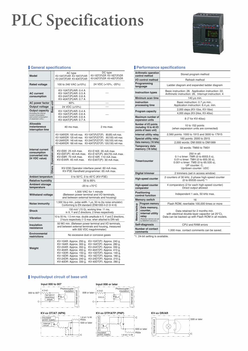
Input 000 to 007
000 to 007
Photocouplerinsulation
24 V/5 Vswitching
circuit
Inte
rnal
circ
uit
Photocouplerinsulation
Inte
rnal
circ
uit
008 or later
Input 008 or later
KV-xx DT/AT (NPN)
Insulated power supply
Insulated power supply
Internal circuit
R50x500 or later
KV-xx DTP/ATP (PNP)
Inte
rnal
circ
uit
Input/output circuit of base unit
PLC Specifications
Rated voltage 100 to 240 VAC (±10%) 24 VDC (+10%, -20%)
AC current consumption
KV-10AT(P)/AR: 0.4 AKV-16AT(P)/AR: 0.5 AKV-24AT(P)/AR: 0.6 AKV-40AT(P)/AR: 0.7 A
AC typeKV-10AT(P)/AR KV-16AT(P)/ARKV-24AT(P)/AR KV-40AT(P)/AR
DC typeKV-10DT(P)/DR KV-16DT(P)/DRKV-24DT(P)/DR KV-40DT(P)/DR
Bas
e u
nit
Model
General specifications
KV-10AT(P)/AR: 0.4 AKV-16AT(P)/AR: 0.6 AKV-24AT(P)/AR: 0.6 AKV-40AT(P)/AR: 0.7 A
Output capacity (Including the internal current consumption and current consumption of expansion units.)
AC power factor 60%Output voltage 24 VDC (±10%)
Allowable instantaneous interruption time
40 ms max. 2 ms max.
Internal current consumption (converted into 24 VDC value)
KV-10AR/DR: 100 mA max. KV-10AT(P)/DT(P): 80(85) mA max.KV-16AR/DR: 120 mA max. KV-16AT(P)/DT(P): 90(100) mA max.KV-24AR/DR: 140 mA max. KV-24AT(P)/DT(P): 100(105) mA max.KV-40AR/DR: 180 mA max. KV-40AT(P)/DT(P): 120(130) mA max.
KV-E8X: 25 mA max.KV-E8T(P): 40 mA max.KV-E8R: 70 mA max.KV-E4XR: 45 mA max.
KV-E16X: 35 mA max.KV-E16T(P): 60(70) mA max.KV-E16R: 110 mA max.KV-E4XT(P): 30 mA max.
Expa
nsio
n un
its
Ambient storage temperature -20 to +70°C
Relative humidity 35 to 85%0 to 50°C, 0 to 45°C (KV-P3E)Ambient temperature
KV-D30 Operator interface panel: 60 mA max.KV-P3E Handheld programmer: 65 mA max.
Oth
ers
Noise immunity 1,500 Vp-p min., pulse width: 1 μs, 50 ns (by noise simulator)Conforming to EN standard (EN61000-4-2/-3/-4/-6)
1,500 VAC for 1 minute (Between power terminal and I/O terminals, and between external terminals and housing)
Withstand voltage
150 m/s2 (15 G), working time: 11 ms, in X, Y and Z directions, 2 times respectivelyShock
10 to 55 Hz, 1.5 mm max. double amplitude in X, Y and Z directions, 2 hours respectively (1 G max. when attached to DIN rail)Vibration
Insulation resistance
50 MΩ min. (Between power terminal and I/O terminals, and between external terminals and housing, measured
with 500 VDC megohmmeter)
Environmental restrictions No excessive dust or corrosive gases
KV-10AR: Approx. 250 g, KV-10AT(P): Approx. 240 g, KV-16AR: Approx. 300 g, KV-16AT(P): Approx. 280 g, KV-24AR: Approx. 350 g, KV-24AT(P): Approx. 330 g, KV-40AR: Approx. 450 g, KV-40AT(P): Approx. 410 g, KV-10DR: Approx. 150 g, KV-10DT(P): Approx. 140 g, KV-16DR: Approx. 190 g, KV-16DT(P): Approx. 180 g, KV-24DR: Approx. 240 g, KV-24DT(P): Approx. 210 g, KV-40DR: Approx. 330 g, KV-40DT(P): Approx. 280 g
Weight
Performance specificationsArithmetic operation control method Stored program method
Programming language Ladder diagram and expanded ladder diagram
I/O control method Refresh method
Basic instruction: 28, Application instruction: 22, Arithmetic instruction: 26, Interrupt instruction: 4Instruction types
Minimum scan time 140 μs min.
Instruction processing time
Basic instruction: 0.7 μs min., Application instruction: 6.4 μs. min.
Program capacity4,000 steps (KV-24xx, KV-40xx)2,000 steps (KV-10xx, KV-16xx)
8 (7 for KV-40xx)Maximum number of expansion units
Number of I/O points (including 10 to 40 I/O points of basic unit)
10 to 152 points (when expansion units are connected)
Internal utility relay 2,560 points: 1000 to 1915 and 3000 to 17915
Special utility relay 160 points: 2000 to 29152,000 words: DM 0000 to DM1999Data memory (16 bits)
Temporary data memory (16 bits) 32 words: TM00 to TM31
Timer/counter
250 in all:0.1-s timer: TMR (0 to 6553.5 s),
0.01-s timer: TMH (0 to 655.35 s), 0.001-s timer: TMS (0 to 65.535 s),
UP counter: C, Up/down counter: UDC
Digital trimmer 2 trimmers (set in access window)
High-speed counter 2 counters of 30 kHz, 2-phase high-speed counter (0 to 65535 count) *1
High-speed counter comparator
4 comparators (2 for each high-speed counter)Direct output allowed
Positioning control function Independent 1 axis, 50 kHz max.
Memory switch 16
Mem
ory
back
up
Program memory Flash ROM, rewritable 100,000 times or moreData memory, counter, internal utility relay(Retention devices are set by MEMSW instruction.)
Data retained for 2 months min. with electrical double-layer capacitor (at 25°C),
Data can be backed up with Flash ROM in all models.
Self-diagnosis
*1. 24-bit setting is available.
Number of contact comments
CPU and RAM errors
1,000 max. contact comments can be saved.
C
500 or later
KV-xx DR/AR
Inte
rnal
circ
uit
C
500 or later
R50x1.6 kΩ 1/2 W
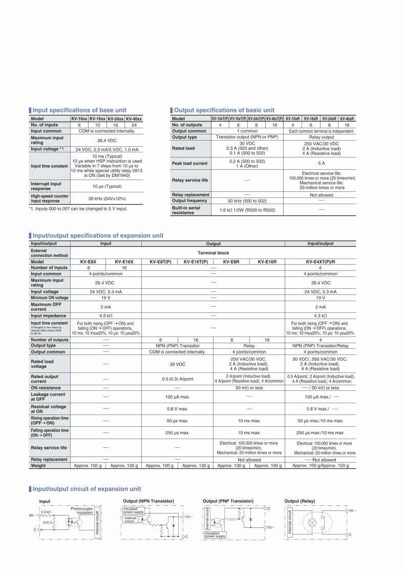
Input specifications of base unit
Input/output specifications of expansion unit
Output specifications of basic unitKV-16xx KV-24xx KV-40xxModel
*1. Inputs 000 to 007 can be changed to 5 V input.
Input common COM is connected internally.
High-speed counter input response 30 kHz (24V±10%)
10 µs (Typical)Interrupt input response
Input time constant
10 ms (Typical)10 µs when HSP instruction is usedVariable in 7 steps from 10 µs to
10 ms while special utility relay 2813 is ON (Set by DM1940)
24 VDC, 5.3 mA/5 VDC, 1.0 mAInput voltage *1
26.4 VDCMaximum input rating
No. of inputs 10KV-10xx
6 16 24
8 16 4
86 16 6 8 16Model KV-16xT(P)
4
KV-10xT(P) KV-24xT(P) KV-40xT(P) KV-16xR4
KV-10xR KV-24xR KV-40xRNo. of outputs
Built-in serial resistance 1.6 kΩ 1/2W (R500 to R502)
Output frequency 50 kHz (500 to 502)Relay replacement Not allowed
Relay service life
Electrical service life: 100,000 times or more (20 times/min)
Mechanical service life: 20-million times or more
0.2 A (500 to 502)1 A (Other)
5 APeak load current
1 common Each common terminal is independent.Output commonOutput type Relay outputTransistor output (NPN or PNP)
Rated load250 VAC/30 VDC
2 A (Inductive load)4 A (Resistive load)
30 VDC0.3 A (503 and other)
0.1 A (500 to 502)
Input/output Input Output Input/output
External connection method Terminal block
KV-E8X KV-E8T(P) KV-E16T(P) KV-E8R KV-E16R KV-E4XT(P)/RKV-E16XModelNumber of inputsInput common 4 points/common 4 points/common
Maximum input rating 26.4 VDC 26.4 VDC
Input voltage 24 VDC, 5.3 mA 24 VDC, 5.3 mAMinimum ON voltage 19 V 19 V
Maximum OFF current 2 mA 2 mA
Input impedance 4.3 kΩ 4.3 kΩ
Input time constant (Changed in two steps by special utility relays 2609 to 2612)
For both rising (OFF ON) and falling (ON OFF) operations,
10 ms: 10 ms±20%, 10 µs: 10 µs±20%
For both rising (OFF ON) and falling (ON OFF) operations,
10 ms: 10 ms±20%, 10 µs: 10 µs±20%
Number of outputs 8 16 8 416NPN (PNP) Transistor Relay NPN (PNP) Transistor/RelayOutput type
Output common COM is connected internally. 4 points/common 4 points/common
30 VDC/, 250 VAC/30 VDC, 2 A (Inductive load), 4 A (Resistive load)
250 VAC/30 VDC, 2 A (Inductive load), 4 A (Resistive load)
30 VDCRated load voltage
Rated output current 0.5 (0.3) A/point 0.5 A/point/, 2 A/point (Inductive load),
4 A (Resistive load), 4 A/common2 A/point (Inductive load),
4 A/point (Resistive load), 4 A/common
50 mΩ or less / 50 mΩ or lessON resistance
100 µA max. 100 µA max./Leakage current at OFF
0.8 V max. 0.8 V max./ Residual voltage at ON
250 µs max./10 ms max.10 ms max.250 µs max.Falling operation time (ON OFF)
Rising operation time (OFF ON) 50 µs max. 10 ms max. 50 µs max./10 ms max.
Electrical: 100,000 times or more (20 times/min),
Mechanical: 20-million times or more
Electrical: 100,000 times or more (20 times/min),
Mechanical: 20-million times or moreRelay service life
/Not allowedNot allowedRelay replacementWeight Approx. 100 g/Approx. 120 gApprox. 100 g Approx. 130 g Approx. 100 g Approx. 130 g Approx. 130 g Approx. 190 g
X0
C
510 Ω
4.3 kΩ
Y0
C
Input/output circuit of expansion unit
Input
Photocouplerinsulation
Inte
rnal
circ
uit
Insulated power supply
Internal circuit
Output (NPN Transistor) Output (PNP Transistor)
Y0
C
Inte
rnal
circ
uit
Output (Relay)
Insulated power supply
Inte
rnal
circ
uit C
Y0