74235 us50 and sheckler draft report
TRANSCRIPT
| NEVADA DEPARTMENT OF TRANSPORTATION | MATERIALS DIVISION |
| GEOTECHNICAL SECTION | 1263 STEWART ST, CARSON CITY, NEVADA 89712 |
GEOTECHNICAL INVESTIGATION
US-50 & SHECKLER SIGNAL POLE FOUNDATION FALLON, NEVADA
EA 74235
SEPTEMBER 2019

STATE OF NEVADA
DEPARTMENT OF TRANSPORTATION
MATERIALS DIVISION
GEOTECHNICAL SECTION
GEOTECHNICAL INVESTIGATION
US-50 AND SHECKLER SIGNAL POLE
FOUNDATIONS
FALLON, NEVADA
SEPTEMBER 2019
EA 74235
Prepared by:
George Helgerson, E.I. Geotechnical Staff
Reviewed by:
Kyle Jermstad, P.E. Principal Geotechnical Engineer
Reviewed by:
Mike Griswold, P.E. Chief Geotechnical Engineer
Approved by:
Darin Tedford, P.E. Chief Materials Engineer

Contents
1. Introduction ........................................................................................................ 1
1.1 Project Description ............................................................................................................. 1
1.2 Purpose and Scope of Work ............................................................................................... 1
1.3 Limitations ........................................................................................................................... 1
2. Field Exploration and Laboratory Testing .......................................................... 2
2.1 Field Exploration ................................................................................................................. 2
2.2 Geotechnical Laboratory Testing........................................................................................ 2
3. Site and Subsurface Conditions ......................................................................... 4
3.1 Site Conditions.................................................................................................................... 4
3.2 Subsurface Conditions ....................................................................................................... 4
3.2.1 General Geology and Faulting ......................................................................................... 4
3.2.2 Subsurface Materials ....................................................................................................... 4
3.2.3 Groundwater Conditions .................................................................................................. 4
4. Recommendations ............................................................................................. 5
4.1 Drilled Shaft Foundations ................................................................................................... 5
4.1.1 Drilled Shaft Construction ................................................................................................ 6
4.2 Corrosion ............................................................................................................................ 6
4.3 Seismic Design ................................................................................................................... 6
5. References ........................................................................................................ 8
Table Index Table 1 Soil Parameters ........................................................................................... 5
Table 2 Design Loads .............................................................................................. 5
Table 3 Drilled Shaft Summary ................................................................................. 6
Table 4 Soil Corrosion Results ................................................................................. 6
Table 5 Seismic Design Criteria ............................................................................... 7

Appendices
A Figures
B Logs of Borings
C Laboratory Test Results
D Axial Resistance Analysis
E Lateral Resistance Analysis

1
Introduction
The Nevada Department of Transportation (NDOT) plans to place two signal poles at the intersection of
US-50 and Sheckler Cutoff/Roberson Lane. This report presents the findings and recommendations
developed from our geotechnical engineering investigation for the proposed signal pole drilled shaft
foundations. The investigation was conducted in accordance with American Association of State Highway
and Traffic Administration (AASHTO) and Federal Highway Administration (FHWA) guidelines.
1.1 Project Description
It is our understanding that this project consists of placing a signal pole in the Northwest corner of US-
50\Roberson Lane intersection and one in the Southeast corner of US-50/Sheckler Cutoff intersection.
These signal poles will have a drilled shaft foundation.
The project Vicinity Map and Exploration Map are shown in Appendix A on Figures A-1 and A-2,
respectively.
1.2 Purpose and Scope of Work
The purpose of this investigation was to evaluate the suitability of the project site from a geotechnical
perspective, for the proposed drilled shafts. The main objectives of the investigation were to characterize
the subsurface materials, perform engineering analyses, develop geotechnical recommendations for
design and construction, and document our findings, and recommendations in this report.
The scope of our geotechnical investigation includes the following:
A review of published geologic and geotechnical information pertaining to the site vicinity;
A field exploration consisting of drilling two borings to a maximum depth of 41½ feet below
ground surface (bgs) to obtain information to evaluate the subsurface conditions;
Perform geotechnical laboratory testing on select soil samples collected from the borings;
Perform engineering analyses to develop geotechnical design criteria and recommendations for
the proposed project; and
Preparation of this report.
1.3 Limitations
This report has been prepared by Nevada Department of Transportation (NDOT) Geotechnical Section
under the supervision of those whose signatures appear herein. The interpretation of data, findings, and
recommendations presented in this report were developed from our geotechnical investigation.
If the proposed project is modified or relocated, or if the subsurface conditions found during construction
differ from those described in this report, NDOT Geotechnical Section should be contacted immediately to
assess the new information or changed conditions and determine if additional recommendations are
required.

2
2. Field Exploration and Laboratory Testing
2.1 Field Exploration
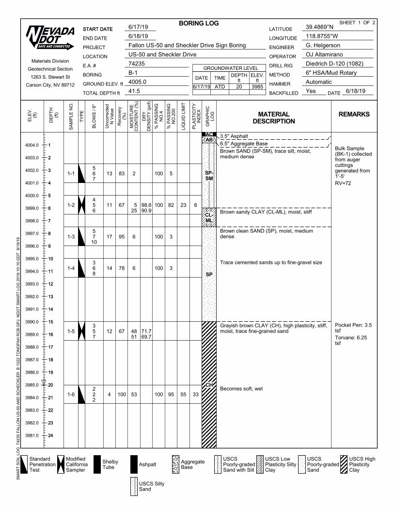
Two Borings were drilled on June 17 through July 23, 2019 at the approximate locations shown on Figure
A-2. The borings were advanced to a depth of approximately 41½ feet bgs utilizing a truck-mounted
Diedrich D-120 (NDOT 1082) drill rig. Drilling methods used were 6-inch hollow stem auger and 3-inch
tricone mud rotary. Samples were collected using Modified California (3-inch outer diameter) and
Standard Penetration Test samplers driven by an automatic hammer with a weight of 140 pounds and a
drop of 30 inches. 3-inch outer diameter Shelby Tube samples were taken in soft soils.
The number of blows required to drive the sampler 6-inches were recorded for the 18-inch drive, and the
cumulative blow count for the bottom 12 inches of drive is presented in the logs of borings. The blow
counts presented in the logs are uncorrected and are shown as they were recorded in the field.
Normalizing the blow counts for use in analysis was performed utilizing corrections for sampler type, rod
length, auger diameter, hammer efficiency, and overburden stress. Both the samples and drill cuttings
were visually classified in the field based on the Unified Soil Classification System (USCS) in general
accordance with ASTM D2488.
Logs of the borings were prepared based on the field logging and the results of laboratory testing in
general accordance with ASTM D2487. The boring logs and key are presented in Appendix B.
2.2 Geotechnical Laboratory Testing
Laboratory testing was conducted on select soil samples recovered during the field exploration. Tests
conducted include the following:
Method of Test Sieve Analysis of Coarse and Fine Aggregate (Nev. T206);
Standard Test Method for Laboratory Determination of Water (Moisture) Content of Soil
(AASHTO T265);
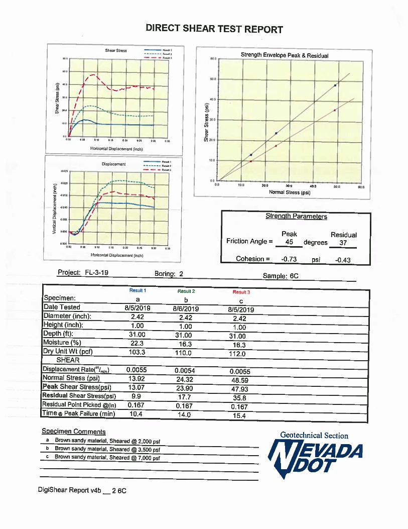
Standard Method of Test for Direct Shear Test of Soils under Consolidated Drained Conditions
(AASHTO T236)
Standard Method of Test for Consolidated, Undrained Triaxial Compression Test on Cohesive
Soils (AASHTO T297)
Standard Method of Test for Unconsolidated, Undrained Compressive Strength of Cohesive Soils
in Triaxial Compression (AASHTO T296)
Method of Test For Determination of The Resistance R-Value of Treated and Untreated Bases,
Subbases and Basement Soils by The Stabilometer (Nev. T115);
Standard Test Methods for Laboratory Determination of Density (ASTM D7263);
Method of Test For Determining The Liquid Limit, Plastic Limit, and Plasticity Index of Soil (Nev.
T210, T211, and T212);
Standard Method of Test for Determining Minimum Laboratory Soil Resistivity (AASHTO T288);
Standard Method of Test for Determining pH of Soil (AASHTO T289);
3
Standard Method of Test for Determining Water-Soluble Sulfate Ion Content in Soil (AASHTO
T290);
Standard Method of Test for Determining Water-Soluble Chloride Ion Content in Soil (AASHTO
T291);
Geotechnical laboratory test results are presented in Appendix C.

4
3. Site and Subsurface Conditions
3.1 Site Conditions
The intersection of US-50 and Sheckler Cutoff/Roberson Lane is located on the West side of Fallon,
Nevada. The site consists of an unsignalized intersection of a five-lane highway (US-50 running East/West)
and two-lane local county roads (Sheckler Cutoff to the South, Roberson Lane to the North). The site
topography is generally flat. At the time of our exploration, three of intersection’s corner lots were developed
commercial land. The fourth corner lot (Northwest) ground surface consisted of sand and gravel with sparse
weeds and brush. Overhead utilities were observed and multiple underground utilities were located at the
site during our subsurface investigation.
3.2 Subsurface Conditions
3.2.1 General Geology and Faulting
The site is located in western portion of the Basin and Range geomorphic province. The site area in the
western part of Churchill County is mapped as being comprised of primarily Quaternary alluvium which
includes Lake Lahontan deposits, playa deposits, and young fan gravels. The young alluvium generally is
composed of fine-grained sediments, silts, and clays. The nearest active fault with historic movement (last
150 years) is the Rainbow Mountain fault zone located approximately 13 miles to the east. Other active
faults nearby include the Dixie fault zone, 1954 section, located approximately 35 miles to the east from
the site. The nearest Quaternary fault is the Sagouse fault zone, located approximately 2 miles to the
north.
3.2.2 Subsurface Materials
The results of our field exploration and laboratory analyses indicate approximately 15 feet of native loose
to medium dense sand (SP) was encountered beneath the roadbed section. Soil beneath the sand
consists of medium stiff to stiff clay (CH) to a depth of approximately 25 feet bgs. Below the clay to the
bottom of the borings was medium dense to very dense sand (SP).
3.2.3 Groundwater Conditions
Groundwater was encountered in the borings during our exploration at 20 feet below ground surface. The
depth of groundwater is expected to vary over time due to seasonal fluctuations, regional pumping, and
other contributing factors. Groundwater is anticipated to be encountered during construction excavations
at approximately 20 feet below ground surface.

5
4. Recommendations
It is our understanding that the proposed signal poles are to be supported by 48-inch diameter drilled
shaft foundations. Based on the results of this exploration, the site is suitable for the proposed
improvements. Provided herein are the recommendations for use in design and construction of the drilled
shaft foundations.
4.1 Drilled Shaft Foundations
Soil parameters used in the analysis of axial and lateral resistance of the drilled shaft foundations were
developed considering the materials encountered in Borings B-1 and B-2 and are presented below in
Table 1.
Table 1 Soil Parameters
Layer Parameters (Boring B-1 / Boring B-2)
Classification Depth Unit Weight (pcf) Internal Friction
Angle Φ (⁰) Cohesion
(psf)
Loose Sand (SP-SM) 0’ – 15’ 108 / 113 35 / 34 -
Medium Dense Clay (CH)
15’ – 25’ 105 / 103 - 2500 / 1500
Dense Sand (SP-SM) 25’ – 41.5’ 129 / 128 38 / 45 -
Design loads were provided by the structural engineer for use in analysis. The loads applied at the head
of the drilled shafts are summarized below in Table 2.
Table 2 Design Loads
Axial (lbs) Moment (ft-lbs) Shear (lbs)
8,733 272,261 4,862
The axial resistance of the drilled shaft foundation soils was analyzed in accordance with the 2017
AASHTO LRFD Bridge Design Specifications (AASHTO 2017), using the computer program SHAFT
(Ensoft, 2017). The results of the axial resistance analysis are presented in Appendix D.
Lateral resistance of the drilled shaft foundation soils was analyzed in accordance with AASHTO 2017,
using the computer program LPILE (Ensoft, 2018). The minimum depth to satisfy lateral demands was
determined considering methods presented FHWA-HIF-18-031, and NDOT Structures Manual Revision
2019-2. Resistance to posting of short drilled shafts was analyzed utilizing Broms Method as detailed in
FHWA-NHI-18-024. The results of the lateral resistance analysis are presented in Appendix E.
Based on the results of our analysis, it is recommended that a 48-inch diameter drilled shaft with a
minimum depth of 32 feet be incorporated into the design of the signal pole foundations. Presented below
in Table 3 are the recommendations for the drilled shaft foundations.

6
Table 3 Drilled Shaft Summary
Shaft Diameter (in.)
Minimum Shaft Length to Satisfy Lateral Demands (ft.)
Minimum Shaft Length to Satisfy Axial Demands (ft)
Design Shaft Length (ft.)
48 32 7 32
4.1.1 Drilled Shaft Construction
Construction of the drilled shafts should follow the NDOT Standard Specifications for Road and Bridge
Construction (Silver Book) section 509. Based on the depth of groundwater encountered in our
subsurface investigation, it is recommended that wet construction methods be used. The slurry elevation
should be kept within 5 feet from the ground surface to maintain an approximate minimum 15-foot head
differential at all times during drilling and placement of concrete.
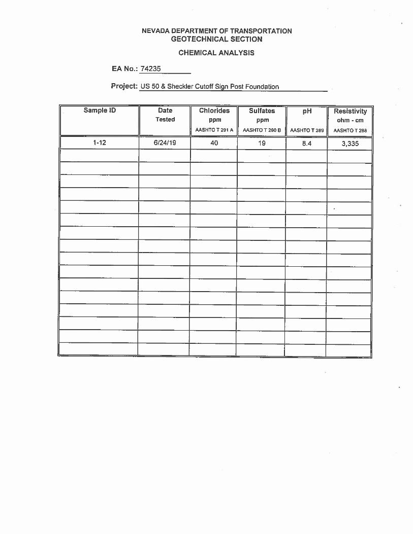
4.2 Corrosion
Soils corrosivity analysis is important for estimating and mitigating the deterioration of buried ferrous
metals and concrete. We performed corrosion testing on a sample from Boring B-1 with a depth range of
1 to 5 feet bgs as an indicator of the corrosive properties of the soil. Test results are summarized below in
Table 3 and presented in Appendix C.
Table 4 Soil Corrosion Results
Boring No. Depth
(ft.) pH
Minimum Resistivity (ohm-cm)
Water Soluble
Sulfates (ppm)
Water Soluble
Chlorides (ppm)
B-1 1-5 8.4 3,335 19 40
According to ACI 318, water soluble sulfates less than 1,000 parts per million is considered “not
applicable”. A water-soluble chloride content of less than 500 ppm is generally non-corrosive to reinforced
concrete.
The provided corrosion test results are only an indicator of potential soil corrosivity for the sample tested
at the selected depth interval. It is possible that corrosion potential can vary by sample location and
depth.
4.3 Seismic Design
The seismic design criteria for the site (39.4871°N, 118.8757°W) were developed utilizing the USGS
seismic hazards tool in accordance with AASHTO 2017, considering the site location, and the subsurface
information obtained from our geotechnical investigation. Minimum seismic criteria for use in design are
listed by county in the NDOT Structures Manual and supersede the USGS mapped values presented
below.

7
Table 5 Seismic Design Criteria
Parameter USGS Mapped
Value
NDOT Structures
Manual Value
Site Class D D
Peak ground acceleration (PGA) 0.232 g 0.35g
Mapped horizontal response spectral response at short period (SS) 0.566 g 0.80g
Mapped horizontal response spectral response at 1sec period (S1) 0.208 g 0.30g
Peak ground acceleration coefficient (FPGA) 1.335 1.15
Site coefficient (Fa) 1.347 1.18
Site coefficient (FV) 1.984 1.8
Mapped MCE peak ground acceleration (AS) 0.310 g 0.403g
Design Spectral Acceleration for short period (SDS) 0.763 g 0.944g
Design Spectral Acceleration for 1 sec period (SD1) 0.413 g 0.54g

8
5. References
American Association of State Highway and Transportation Officials (AASHTO), 2017, “LRFD Bridge
Design Specifications, 8th Edition”
Brown, Dan, et al, 2018, “FHWA-NHI-18-024 Drilled Shafts”
Loehr, Erik, et al, 2016, “FHWA NHI-16-072 Geotechnical Site Characterization”
Mayne, W. Paul, et al, 2002, “FHWA-NHI-01-031 Subsurface Investigation Manual”
Nevada Department of Transportation (NDOT), 2008, “Structures Manual”
Nevada Department of Transportation (NDOT), 2019, “Structures Manual Revision”
Nevada Department of Transportation (NDOT), 2014, “Standard Specifications for Road and Bridge
Construction”
Parkes, James, et al, 2018, “FHWA-HIF-18-031 Design, Analysis, and Testing of Laterally Loaded Deep
Foundations that Support Transportation Facilities”
Sabatini, P.J., et al, 2002, “FHWA-IF-02-034 Evaluation of Soil and Rock Properties”
Stewart, John H., and Carlson, John E., 1978, “Geologic map of Nevada, Nevada Bureau of Mines and
Geology, scale 1:500,00.”
U.S. Geologic Survey, March 19, 2018, U.S. Seismic Design Maps,
http://earthquake.usgs.gov/designmaps/us/application.php

Appendix A
Figures

Figure A-1 Vicinity Map
Location: Fallon, NV
Project Name: US50 & Sheckler Cutoff
EA Number: 74235
1263 South Stewart Street
Carson City, Nevada 89712
Phone: (775) 888-7440
Fax: (775) 888-7201

Figure A-2 Exploration Map
Location: Fallon, NV
Project Name: US50 & Sheckler Cutoff
EA Number: 74235
1263 South Stewart Street
Carson City, Nevada 89712
Phone: (775) 888-7440
Fax: (775) 888-7201

Appendix B
Logs of Borings

KEY TO BORING LOGS
USCS GROUP TYPICAL SOIL DESCRIPTION
GW GP GC SW SP SM SC ML CL OL
MH CH OH CS PT
Well graded gravels, gravel-sand mixtures, little or no fines Poorly graded gravels, gravel-sand mixtures, little or no fines Clayey gravels, poorly graded gravel-sand-clay mixtures Well graded sands, gravelly sands, little or no fines Poorly graded sands, gravelly sands, little or no fines Silty sands, poorly graded sand-silt mixtures Clayey sands, poorly graded sand-clay mixtures Inorganic silts and very fine sands, rock flour, silty or clayey fine sands with slight plasticity Inorganic clays of low to medium plasticity, gravelly clays, sandy clays, silty clays, lean clays Organic silts and organic silt-clays of low plasticity Inorganic silts, micaceous or diatomaceous fine sandy or silty soils, elastic silts Inorganic clays of high plasticity, fat clays Organic clays of medium to high plasticity Claystone/Siltstone Peat and other highly organic soils
MOISTURE CONDITION CRITERIA SOIL CEMENTATION CRITERIA
Description Criteria Description Criteria Dry Absence of moisture, dusty, Weak Crumbles or breaks with handling or little dry to touch. finger pressure. Moist Damp, no visible free water. Moderate Crumbles or breaks with considerable finger pressure Wet Visible free water, usually below
groundwater table. Strong Won’t break or crumble w/finger pressure
Groundwater Elevation Symbols
Blow counts on Calif. Modified
Sampler (NCMS) can be converted
to NSPT by:
(NCMS)(0.62) = NSPT
Automatic Hammer Engergy: Rig # 1627: 82.5% Rig # 1082: 84%
TEST ABBREVIATIONS
CD CONSOLIDATED DRAINED CH CHEMICAL (CORROSIVENESS) CM COMPACTION CU CONSOLIDATED UNDRAINED D DISPERSIVE SOILS DS DIRECT SHEAR E EXPANSIVE SOIL G SPECIFIC GRAVITY H HYDROMETER HC HYDRO-COLLAPSE K PERMEABILITY
O ORGANIC CONTENT OC CONSOLIDATION PI PLASTICITY INDEX RQD ROCK QUALITY DESIGNATION RV R-VALUE S SIEVE ANALYSIS SL SHRINKAGE LIMIT U UNCONFINED COMPRESSION UU UNCONSOLIDATED UNDRAINED UW UNIT WEIGHT W MOISTURE CONTENT
SAMPLER NOTATION
CMS CALIF. MODIFIED SAMPLER1
CPT CONE PENETRATION TEST CS CONTINUOUS SAMPLER2
CSS CALIFORNIA SPLIT SPOON P PUSHED (NOT DRIVEN) PB PITCHER BARREL RC ROCK CORE3
SH SHELBY TUBE4
SPT STANDARD PENETRATION TEST TP TEST PIT 1- I.D.= 2.421 inch
2- I.D.=3.228 inch with tube; 3.50 inch w/o tube
3- NXB I.D.= 1.875 inch
4- I.D.= 2.875 inch
SOIL COLOR DESIGNATIONS ARE FROM THE MUNSELL SOIL COLOR CHART.
EXAMPLE: (7.5 YR 5/3) BROWN
Revised June 2018
PARTICLE SIZE LIMITSCLAY SILT SAND GRAVEL COBBLES BOULDERS
FINE MEDIUM COARSE FINE COARSE
.002 mm #200 #40 #10 #4 ¾ inch 3 inch 12 inch
STANDARD PENETRATION CLASSIFICATION* GRANULAR SOIL CLAYEY SOIL
BLOWS/FT DENSITY BLOWS/FT CONSISTENCY
0 - 4
5 – 10
11 - 30
31 - 50
OVER 50
VERY LOOSE
LOOSE
MEDIUM DENSE
DENSE
VERY DENSE
0 - 1 VERY SOFT
2 - 4 SOFT
5 - 8 MEDIUM STIFF
9 - 15 STIFF
16 - 30 VERY STIFF
31 - 60 HARD
OVER 60 VERY HARD *Standard Penetration Test (N) 140 lb hammer 30-inch free fall on 2-inch O.D. x 1.4 inch I.D. sampler.
3.5" Asphalt
6.5" Aggregate Base
Brown SAND (SP-SM), trace silt, moist,medium dense
Brown sandy CLAY (CL-ML), moist, stiff
Brown clean SAND (SP), moist, mediumdense
Trace cemented sands up to fine-gravel size
Grayish brown CLAY (CH), high plasticity, stiff,moist, trace fine-grained sand
Becomes soft, wet
100
100
100
100
100
23
55
Bulk Sample(BK-1) collectedfrom augercuttingsgenerated from1'-5'RV=72
Pocket Pen: 3.5tsfTorvane: 6.25tsf
6
33
13
11
17
14
12
4
1-1
1-2
1-3
1-4
1-5
1-6
567
456
5710
368
357
222
83
67
95
78
67
100
2
525
6
6
4851
53
98.690.9
71.769.7
5
82
3
3
95
DATE
LOCATION
B-1
Fallon US-50 and Sheckler Drive Sign Boring
6/18/19
6/17/19BORING LOG
E.A. #
BORING 6" HSA/Mud Rotary
OPERATOR OJ Altamirano
74235
4005.0
PROJECT
METHOD
39.4869°N
ENGINEER G. Helgerson
118.8755°W
DRILL RIG
LONGITUDE
Diedrich D-120 (1082)
BACKFILLED
Materials Division
Geotechnical Section
1263 S. Stewart St
Carson City, NV 89712
START DATE
END DATE
6/18/19Yes
US-50 and Sheckler Drive
SHEET 1 OF 2
HAMMER Automatic
TOTAL DEPTH ft 41.5GROUND ELEV. ft
START DATE LATITUDE
StandardPenetrationTest
ModifiedCaliforniaSampler
ShelbyTube Ashpalt Aggregate
Base
USCSPoorly-gradedSand with Silt
USCS LowPlasticity SiltyClay
USCSPoorly-gradedSand
USCS HighPlasticityClay
USCS SiltySand
SM
AR
T S
OIL
LO
G 7
4235
FA
LLO
N U
S-5
0 A
ND
SC
HE
CK
LER
B 1
022
TO
NO
PA
H R
CB
.GP
J N
DO
T S
MA
RT
LO
G 2
018
.10
.10.
GD
T 9
/19/
19
39856/17/19 ATD
DATE TIME DEPTHft
ELEV.ft
GROUNDWATER LEVEL
20
DE
PT
H(f
t)
1
2
3
4
5
6
7
8
9
10
11
12
13
14
15
16
17
18
19
20
21
22
23
24
1
2
3
4
5
6
7
8
9
10
11
12
13
14
15
16
17
18
19
20
21
22
23
24
ELE
V.
(ft)
4004.0
4003.0
4002.0
4001.0
4000.0
3999.0
3998.0
3997.0
3996.0
3995.0
3994.0
3993.0
3992.0
3991.0
3990.0
3989.0
3988.0
3987.0
3986.0
3985.0
3984.0
3983.0
3982.0
3981.0
GR
AP
HIC
LOG
% P
AS
SIN
GN
O.4
LIQ
UID
LIM
IT
REMARKSMATERIALDESCRIPTION
PLA
ST
ICIT
YIN
DE
X
BLO
WS
/ 6"
SA
MP
LE N
O.
Unc
orre
cted
N V
alue
Rec
over
y(%
)
TY
PE
MO
IST
UR
EC
ON
TE
NT
(%
)
DR
YD
EN
SIT
Y (
pcf)
% P
AS
SIN
GN
O.2
00
ACAB
SP-SM
CL-ML
SP
CH

Brown SAND (SP-SM), fine- tomedium-grained sand, medium dense, wet,trace silt
Brown silty Sand (SM), fine- tomedium-grained sand, dense, wet
Brown SAND (SP), fine- to medium-grainedsand, very dense, wet
100
100
99
Shelby PushPressure: 300psi
23
27
51
1-7/8
1-9
1-10
1-11
81013
131017
222526
67
50
100
100
1519
21
20
109 11
20
4
DATE
LOCATION
B-1
Fallon US-50 and Sheckler Drive Sign Boring
6/18/19
6/17/19BORING LOG
E.A. #
BORING 6" HSA/Mud Rotary
OPERATOR OJ Altamirano
74235
4005.0
PROJECT
METHOD
39.4869°N
ENGINEER G. Helgerson
118.8755°W
DRILL RIG
LONGITUDE
Diedrich D-120 (1082)
BACKFILLED
Materials Division
Geotechnical Section
1263 S. Stewart St
Carson City, NV 89712
START DATE
END DATE
6/18/19Yes
US-50 and Sheckler Drive
SHEET 2 OF 2
HAMMER Automatic
TOTAL DEPTH ft 41.5GROUND ELEV. ft
START DATE LATITUDE
StandardPenetrationTest
ModifiedCaliforniaSampler
ShelbyTube Ashpalt Aggregate
Base
USCSPoorly-gradedSand with Silt
USCS LowPlasticity SiltyClay
USCSPoorly-gradedSand
USCS HighPlasticityClay
USCS SiltySand
SM
AR
T S
OIL
LO
G 7
4235
FA
LLO
N U
S-5
0 A
ND
SC
HE
CK
LER
B 1
022
TO
NO
PA
H R
CB
.GP
J N
DO
T S
MA
RT
LO
G 2
018
.10
.10.
GD
T 9
/19/
19
39856/17/19 ATD
DATE TIME DEPTHft
ELEV.ft
GROUNDWATER LEVEL
20
DE
PT
H(f
t)
26
27
28
29
30
31
32
33
34
35
36
37
38
39
40
41
42
43
44
45
46
47
48
49
26
27
28
29
30
31
32
33
34
35
36
37
38
39
40
41
42
43
44
45
46
47
48
49
ELE
V.
(ft)
3979.0
3978.0
3977.0
3976.0
3975.0
3974.0
3973.0
3972.0
3971.0
3970.0
3969.0
3968.0
3967.0
3966.0
3965.0
3964.0
3963.0
3962.0
3961.0
3960.0
3959.0
3958.0
3957.0
3956.0
GR
AP
HIC
LOG
% P
AS
SIN
GN
O.4
LIQ
UID
LIM
IT
REMARKSMATERIALDESCRIPTION
PLA
ST
ICIT
YIN
DE
X
BLO
WS
/ 6"
SA
MP
LE N
O.
Unc
orre
cted
N V
alue
Rec
over
y(%
)
TY
PE
MO
IST
UR
EC
ON
TE
NT
(%
)
DR
YD
EN
SIT
Y (
pcf)
% P
AS
SIN
GN
O.2
00
SP-SM
SM
SP

7" Asphalt
7" Aggregate Base
Brown SAND with silt (SP-SM), moist, loose
Grayish brown CLAY (CH), high plasticity, stiff,moist, trace fine-grained sand
Becomes medium stiff
100
100
100
18
67
60
Pocket Pen: 3.0tsfTorvane: 5.0 tsf
Pocket Pen:1.75 tsfTorvane: 5.5 tsf
Shelby PushPressure:Weight of rods,no additionalpressure
18
45
40
4
5
14
6
2-1
2-2
2-3
2-4
2-ST
222
323
668
333
67
56
67
67
100
17
16
4150
5067
71
60
12
90
96
DATE
LOCATION
B-2
Fallon US-50 and Sheckler Drive Sign Boring
7/23/19
7/23/19BORING LOG
E.A. #
BORING 6" Mud Rotary
OPERATOR OJ Altamirano
74235
4004.0
PROJECT
METHOD
39.4867°N
ENGINEER G. Helgerson
118.8761°W
DRILL RIG
LONGITUDE
Diedrich D-120 (1082)
BACKFILLED
Materials Division
Geotechnical Section
1263 S. Stewart St
Carson City, NV 89712
START DATE
END DATE
7/23/19Yes
US-50 and Sheckler Drive
SHEET 1 OF 2
HAMMER Automatic
TOTAL DEPTH ft 41.5GROUND ELEV. ft
START DATE LATITUDE
StandardPenetrationTest
ModifiedCaliforniaSampler
ShelbyTube Ashpalt Aggregate
Base
USCSPoorly-gradedSand with Silt
USCS HighPlasticityClay
USCS SiltySand
SM
AR
T S
OIL
LO
G 7
4235
FA
LLO
N U
S-5
0 A
ND
SC
HE
CK
LER
B 1
022
TO
NO
PA
H R
CB
.GP
J N
DO
T S
MA
RT
LO
G 2
018
.10
.10.
GD
T 9
/19/
19
39847/23/19 ATD
DATE TIME DEPTHft
ELEV.ft
GROUNDWATER LEVEL
20
DE
PT
H(f
t)
1
2
3
4
5
6
7
8
9
10
11
12
13
14
15
16
17
18
19
20
21
22
23
24
1
2
3
4
5
6
7
8
9
10
11
12
13
14
15
16
17
18
19
20
21
22
23
24
ELE
V.
(ft)
4003.0
4002.0
4001.0
4000.0
3999.0
3998.0
3997.0
3996.0
3995.0
3994.0
3993.0
3992.0
3991.0
3990.0
3989.0
3988.0
3987.0
3986.0
3985.0
3984.0
3983.0
3982.0
3981.0
3980.0
GR
AP
HIC
LOG
% P
AS
SIN
GN
O.4
LIQ
UID
LIM
IT
REMARKSMATERIALDESCRIPTION
PLA
ST
ICIT
YIN
DE
X
BLO
WS
/ 6"
SA
MP
LE N
O.
Unc
orre
cted
N V
alue
Rec
over
y(%
)
TY
PE
MO
IST
UR
EC
ON
TE
NT
(%
)
DR
YD
EN
SIT
Y (
pcf)
% P
AS
SIN
GN
O.2
00
AC
AB
SP-SM
CH

Brown silty SAND(SM), dense, slight mottling,wet
Brown Sand (SP-SM), very dense to dense,wet
Silt content decreases
100
97
99
18 18
20
63
37
51
2-5
2-6
2-7
2-8
6911
213132
131819
182526
67
67
83
78
21
1916
22
20
107
18
11
5
DATE
LOCATION
B-2
Fallon US-50 and Sheckler Drive Sign Boring
7/23/19
7/23/19BORING LOG
E.A. #
BORING 6" Mud Rotary
OPERATOR OJ Altamirano
74235
4004.0
PROJECT
METHOD
39.4867°N
ENGINEER G. Helgerson
118.8761°W
DRILL RIG
LONGITUDE
Diedrich D-120 (1082)
BACKFILLED
Materials Division
Geotechnical Section
1263 S. Stewart St
Carson City, NV 89712
START DATE
END DATE
7/23/19Yes
US-50 and Sheckler Drive
SHEET 2 OF 2
HAMMER Automatic
TOTAL DEPTH ft 41.5GROUND ELEV. ft
START DATE LATITUDE
StandardPenetrationTest
ModifiedCaliforniaSampler
ShelbyTube Ashpalt Aggregate
Base
USCSPoorly-gradedSand with Silt
USCS HighPlasticityClay
USCS SiltySand
SM
AR
T S
OIL
LO
G 7
4235
FA
LLO
N U
S-5
0 A
ND
SC
HE
CK
LER
B 1
022
TO
NO
PA
H R
CB
.GP
J N
DO
T S
MA
RT
LO
G 2
018
.10
.10.
GD
T 9
/19/
19
39847/23/19 ATD
DATE TIME DEPTHft
ELEV.ft
GROUNDWATER LEVEL
20
DE
PT
H(f
t)
26
27
28
29
30
31
32
33
34
35
36
37
38
39
40
41
42
43
44
45
46
47
48
49
26
27
28
29
30
31
32
33
34
35
36
37
38
39
40
41
42
43
44
45
46
47
48
49
ELE
V.
(ft)
3978.0
3977.0
3976.0
3975.0
3974.0
3973.0
3972.0
3971.0
3970.0
3969.0
3968.0
3967.0
3966.0
3965.0
3964.0
3963.0
3962.0
3961.0
3960.0
3959.0
3958.0
3957.0
3956.0
3955.0
GR
AP
HIC
LOG
% P
AS
SIN
GN
O.4
LIQ
UID
LIM
IT
REMARKSMATERIALDESCRIPTION
PLA
ST
ICIT
YIN
DE
X
BLO
WS
/ 6"
SA
MP
LE N
O.
Unc
orre
cted
N V
alue
Rec
over
y(%
)
TY
PE
MO
IST
UR
EC
ON
TE
NT
(%
)
DR
YD
EN
SIT
Y (
pcf)
% P
AS
SIN
GN
O.2
00
SM
SP-SM

Appendix C
Laboratory Test Results


0
2
4
6
8
10
12
14
16
18
20
0 2 4 6 8 10 12 14 16 18 20
Sh
ear
Str
ess
(psi
)
Axial Strain (%)
Triaxial Compression Lab Test Results
Boring 1 Sample 5B
Boring 1 Sample 5C
Boring 2 Sample 3C
Boring 2 Sample 4C

Appendix D
Axial Resistance Analysis

Ultimate Axial Capacity (tons)D
epth
(ft
)
0 50 100 150 200 250 300 350 400 450 5000
24
68
1012
1416
1820
2224
2628
3032
3436
38
Skin Friction
Tip Resistance
Total Capacity
Ultimate Axial Capacity (tons)D
epth
(ft
)
0 50 100 150 200 250 300 350 400 450 500
24
68
1012
1416
1820
2224
2628
3032
3436
38
Skin Friction
Tip Resistance
Total Capacity
Appendix E
Lateral Resistance Analysis

Lateral Pile Deflection (inches)D
epth
(ft
)
-0.01 -0.005 0 0.005 0.01 0.015 0.02 0.025 0.03 0.035 0.04 0.0450
24
68
1012
1416
1820
2224
2628
3032
3436
38
Load Case 1
Sand
Stf. Cl. NW
Stf. Cl. W
Lateral Pile Deflection (inches)D
epth
(ft
)
-0.01 -0.005 0 0.005 0.01 0.015 0.02 0.025 0.03 0.035 0.04 0.0450
24
68
1012
1416
1820
2224
2628
3032
3436
38
Load Case 1
Sand
Stf. Cl. NW
Stf. Cl. W

NEVADA DEPARTMENT OF TRANSPORTATION
Materials Division Geotechnical Section
1263 Stewart St, Carson City, NV 89712