8210 na operator manual (en)d2z4qs2e3spnc1.cloudfront.net/.../453/8210_gas-lpg_operator_man… ·...
TRANSCRIPT
8210
*330190*www.tennantco.com
Operator Manual
330190Rev. 08 (3-2006)

Thismanual is furnished with each newmodel. It providesnecessary operation and maintenance instructions.
Read thismanual completely andunderstand thema-chine before operating or servicing it.
This machine will provide excellent service. However, thebest results will be obtained at minimum costs if:
S The machine is operated with reasonable care.
S The machine is maintained regularly - per the ma-chine maintenance instructions provided.
S The machine is maintained with manufacturer sup-plied or equivalent parts.
PROTECT THE ENVIRONMENTPlease dispose of packaging materials,old machine components such asbatteries, hazardous fluids such asantifreeze and oil, in a safeenvironmentally way according to yourlocal waste disposal regulations.
Always remember to recycle.
MACHINE DATA
Please fill out at time of installation for future reference.
Model No.- 8210
Serial No.-
Machine Options --
Sales Rep. --
Sales Rep. phone no. --
Customer Number --
Installation Date --
Tennant CompanyPO Box 1452Minneapolis, MN 55440Phone: (800) 553--8033 or (763) 523--2850
CALIFORNIA PROPOSITION 65 WARNING:Engine exhaust from this product contains chemicals known to the State of California to cause cancer,birth defects, or other reproductive harm.
MAXPRO and ES are United States registered trademarks of the Tennant Company
Thermo Sentry is a United States trademark of Tennant Company.
Specifications and parts are subject to change without notice.
Copyright E 1998--2000, 2002--2006 TENNANT, Printed in U.S.A.
CONTENTS
18210 330190 (3--06)
CONTENTS
PageSAFETY PRECAUTIONS 3. . . . . . . . . . . . . . . . . . .OPERATION 7. . . . . . . . . . . . . . . . . . . . . . . . . . . . . .
OPERATOR RESPONSIBILITY 7. . . . . . . . . . .MACHINE COMPONENTS 8. . . . . . . . . . . . . . .SYMBOL DEFINITIONS 9. . . . . . . . . . . . . . . . . .CONTROLS AND INSTRUMENTS 11. . . . .OPERATION OF CONTROLS 12. . . . . . . . .
DIRECTIONAL PEDAL 12. . . . . . . . . . . . .BRAKE PEDAL 13. . . . . . . . . . . . . . . . . . .PARKING BRAKE PEDAL 13. . . . . . . . . .IGNITION SWITCH 13. . . . . . . . . . . . . . . .STEERING WHEEL 14. . . . . . . . . . . . . . .STEERING COLUMN TILT LEVER 14. .CHECK ENGINE LIGHT (GM ENGINE) 14SCRUB SWITCH 15. . . . . . . . . . . . . . . . . .SWEEP SWITCH 16. . . . . . . . . . . . . . . . . .SIDE BRUSH SWITCH 16. . . . . . . . . . . . .HOURMETER 17. . . . . . . . . . . . . . . . . . . .FUEL LEVEL GAUGE 17. . . . . . . . . . . . . .HOPPER LEVER 18. . . . . . . . . . . . . . . . . .MAIN SWEEP BRUSH DOWN
PRESSURE KNOB 18. . . . . . . . . . . . .SIDE BRUSH DOWN PRESSURE
HANDLE 19. . . . . . . . . . . . . . . . . . . . . .CONTROL PANEL 19. . . . . . . . . . . . . . . . .SETTING THE DISPLAY CLOCK 20. . . .MAINTENANCE MODE 21. . . . . . . . . . . .
RESETTING THE MAINTENANCETIMERS 22. . . . . . . . . . . . . . . . . . . .
DISABLING THE MAINTENANCEMODE 23. . . . . . . . . . . . . . . . . . . . . .
OPERATING LIGHTS SWITCH 24. . . . .OPERATING/HAZARD LIGHT
SWITCH (OPTION) 24. . . . . . . . . . . . .SOLUTION FLOW SWITCH 24. . . . . . . .MANUAL FLOW VALVE 25. . . . . . . . . . . .ENGINE CHOKE KNOB
(FORD ENGINE) 25. . . . . . . . . . . . . . .SWEEP VACUUM FAN SWITCH 25. . . .HOPPER DOOR SWITCH 26. . . . . . . . . .FILTER SHAKER SWITCH 26. . . . . . . . .EDGE SCRUB SWITCH 27. . . . . . . . . . . .SQUEEGEE SWITCH 27. . . . . . . . . . . . . .ES SWITCH (OPTION) 28. . . . . . . . . . . . .DETERGENT PUMP SWITCH
(OPTION) 29. . . . . . . . . . . . . . . . . . . . .ENGINE SPEED SWITCH 29. . . . . . . . . .CHARGING SYSTEM LIGHT 30. . . . . . .ENGINE OIL PRESSURE LIGHT 30. . . .ENGINE WATER TEMPERATURE
LIGHT 30. . . . . . . . . . . . . . . . . . . . . . . . .HOPPER TEMPERATURE LIGHT --
THERMO SENTRY 31. . . . . . . . . . . . .CLOGGED FILTER LIGHT (OPTION) 31
PageHOPPER DOOR CLOSED LIGHT
(OPTION) 32. . . . . . . . . . . . . . . . . . . . .HYDRAULIC FILTER BYPASS LIGHT
(OPTION) 32. . . . . . . . . . . . . . . . . . . . .HORN BUTTON 32. . . . . . . . . . . . . . . . . . .CIRCUIT BREAKERS 33. . . . . . . . . . . . . .FUSES (GM ENGINE) 33. . . . . . . . . . . . .OPERATOR SEAT 34. . . . . . . . . . . . . . . . .DELUXE SUSPENSION SEAT
(OPTION) 34. . . . . . . . . . . . . . . . . . . . .HOPPER SUPPORT BAR 35. . . . . . . . . .ENGINE COVER GAS SPRING 35. . . . .LATCHES 35. . . . . . . . . . . . . . . . . . . . . . . .
HOW THE MACHINE WORKS 36. . . . . . . . .PRE-OPERATION CHECKLIST 37. . . . . . . .CHANGING AN LPG FUEL TANK 38. . . . . .STARTING THE MACHINE 40. . . . . . . . . . . .SWEEPING, SCRUBBING, AND
BRUSH INFORMATION 42. . . . . . . . . . . .SWEEPING 44. . . . . . . . . . . . . . . . . . . . . . . . .STOP SWEEPING 45. . . . . . . . . . . . . . . . . . .EMPTYING THE HOPPER 46. . . . . . . . . . . .FILLING THE TANKS 48. . . . . . . . . . . . . . . . .SCRUBBING 50. . . . . . . . . . . . . . . . . . . . . . . .DOUBLE SCRUBBING 53. . . . . . . . . . . . . . . .STOP SCRUBBING 53. . . . . . . . . . . . . . . . . .DRAINING AND CLEANING THE TANKS 54STOP THE MACHINE 57. . . . . . . . . . . . . . . .POST-OPERATION CHECKLIST 59. . . . . . .ENGAGING HOPPER SUPPORT BAR 60.DISENGAGING HOPPER SUPPORT
BAR 62. . . . . . . . . . . . . . . . . . . . . . . . . . . . .OPERATION ON INCLINES 63. . . . . . . . . . .TIE DOWNS 63. . . . . . . . . . . . . . . . . . . . . . . . .MACHINE TROUBLESHOOTING 64. . . . . .
MAINTENANCE 66. . . . . . . . . . . . . . . . . . . . . . . .MAINTENANCE CHART 66. . . . . . . . . . . . . .LUBRICATION 68. . . . . . . . . . . . . . . . . . . . . . .
ENGINE (FORD) 68. . . . . . . . . . . . . . . . . .ENGINE (GM) 68. . . . . . . . . . . . . . . . . . . .REAR WHEEL SUPPORT 69. . . . . . . . . .FRONT WHEEL BEARINGS 70. . . . . . . .HOPPER LIFT ARM PIVOTS 70. . . . . . .SCRUB HEAD DRAG LINK ARMS 70. . .
HYDRAULICS 71. . . . . . . . . . . . . . . . . . . . . . .HYDRAULIC FLUID RESERVOIR 71. . .HYDRAULIC FLUID 72. . . . . . . . . . . . . . .HYDRAULIC HOSES 73. . . . . . . . . . . . . .PROPELLING MOTOR 73. . . . . . . . . . . . .
ENGINE 74. . . . . . . . . . . . . . . . . . . . . . . . . . . .COOLING SYSTEM 74. . . . . . . . . . . . . . .AIR FILTER INDICATOR (OPTIONAL) 75AIR FILTER 75. . . . . . . . . . . . . . . . . . . . . . .FUEL FILTER (GASOLINE) 76. . . . . . . . .FUEL FILTER (GM LPG) 76. . . . . . . . . . .SPARK PLUGS 76. . . . . . . . . . . . . . . . . . .CRANKCASE VENTILATION SYSTEM 76
CONTENTS
8210 330190 (3--06)2
PageINTAKE MANIFOLD (FORD) 76. . . . . . . .TIMING BELT (GM) 76. . . . . . . . . . . . . . . .BATTERY 77. . . . . . . . . . . . . . . . . . . . . . . .
BELTS AND CHAINS 78. . . . . . . . . . . . . . . . .ENGINE AND ACCESSORY PUMP BELT
(FORD) 78. . . . . . . . . . . . . . . . . . . . . . .ENGINE BELT (GM) 78. . . . . . . . . . . . . . .STATIC DRAG CHAIN 79. . . . . . . . . . . . .
DEBRIS HOPPER 80. . . . . . . . . . . . . . . . . . . .HOPPER DUST FILTER 80. . . . . . . . . . . .
REMOVING HOPPER DUSTFILTER 81. . . . . . . . . . . . . . . . . . . . .
THERMO SENTRY 81. . . . . . . . . . . . . . . .SCRUB HEAD 82. . . . . . . . . . . . . . . . . . . . . . .BRUSHES 82. . . . . . . . . . . . . . . . . . . . . . . . . . .
MAIN SWEEP BRUSH 82. . . . . . . . . . . . .REPLACING MAIN SWEEP
BRUSH 83. . . . . . . . . . . . . . . . . . . . .CHECKING AND ADJUSTING MAIN
SWEEP BRUSH PATTERN 85. . .SIDE BRUSH 87. . . . . . . . . . . . . . . . . . . . .
REPLACING SIDE BRUSH 88. . . . . .SCRUB BRUSHES 89. . . . . . . . . . . . . . . .
REPLACING THE SCRUBBRUSHES 90. . . . . . . . . . . . . . . . . .
SOLUTION SYSTEM 90. . . . . . . . . . . . . . . . .RECOVERY TANK 90. . . . . . . . . . . . . . . .SOLUTION TANK 91. . . . . . . . . . . . . . . . .
SQUEEGEES 91. . . . . . . . . . . . . . . . . . . . . . . .REAR SQUEEGEE 91. . . . . . . . . . . . . . . .
LEVELING THE REAR SQUEEGEE 92ADJUSTING REAR SQUEEGEE
BLADE DEFLECTION 93. . . . . . . .SIDE SQUEEGEES 94. . . . . . . . . . . . . . . . . .
ADJUSTING THE SIDE SQUEEGEES 94SQUEEGEE BLADES 94. . . . . . . . . . . . . . . .
REAR SQUEEGEE 94. . . . . . . . . . . . . . . .REPLACING OR ROTATING REAR
SQUEEGEE BLADES 94. . . . . . . .SIDE SQUEEGEES 95. . . . . . . . . . . . . . . . . .
REPLACING SIDE SQUEEGEEBLADES 95. . . . . . . . . . . . . . . . . . . . . . .
SKIRTS AND SEALS 96. . . . . . . . . . . . . . . . .REAR SKIRTS 96. . . . . . . . . . . . . . . . . . . .BRUSH DOOR SEALS 96. . . . . . . . . . . . .HOPPER LIP SKIRTS 96. . . . . . . . . . . . . .HOPPER SEALS 97. . . . . . . . . . . . . . . . . .HOPPER DOOR SEALS 97. . . . . . . . . . .HOPPER FILTER SEALS 97. . . . . . . . . . .HOPPER VACUUM FAN SEAL 98. . . . . .TANK COVER SEALS 98. . . . . . . . . . . . .
BRAKES AND TIRES 99. . . . . . . . . . . . . . . . .SERVICE BRAKES 99. . . . . . . . . . . . . . . .PARKING BRAKE 99. . . . . . . . . . . . . . . . .TIRES 99. . . . . . . . . . . . . . . . . . . . . . . . . . .REAR WHEEL 99. . . . . . . . . . . . . . . . . . . .
PagePUSHING, TOWING, AND
TRANSPORTING THE MACHINE 100. . .PUSHING OR TOWING
THE MACHINE 100. . . . . . . . . . . . . . . . .TRANSPORTING THE MACHINE 101. . .
MACHINE JACKING 103. . . . . . . . . . . . . . . . . .STORING MACHINE 103. . . . . . . . . . . . . . . . .
SPECIFICATIONS 104. . . . . . . . . . . . . . . . . . . . . .GENERAL MACHINE PERFORMANCE 104.POWER TYPE 105. . . . . . . . . . . . . . . . . . . . . . .STEERING 105. . . . . . . . . . . . . . . . . . . . . . . . . .HYDRAULIC SYSTEM 106. . . . . . . . . . . . . . . .BRAKING SYSTEM 106. . . . . . . . . . . . . . . . . .TIRES 106. . . . . . . . . . . . . . . . . . . . . . . . . . . . . .MACHINE DIMENSIONS 107. . . . . . . . . . . . . .
INDEX 108. . . . . . . . . . . . . . . . . . . . . . . . . . . . . . . . .
SAFETY PRECAUTIONS
38210 330190 (9--05)
SAFETY PRECAUTIONS
The following precautions are used throughoutthis manual as indicated in their description:
WARNING: To warn of hazards orunsafe practices that could result insevere personal injury or death.
FOR SAFETY: To identify actions thatmust be followed for safe operation ofequipment.
CAUTION: To warn of unsafe practicesthat could result in minor or moderatepersonal injury.
The machine is suited to sweep disposabledebris. Do not use the machine other thandescribed in this Operator Manual. The machineis not designed for use on public roads.
The following information signals potentiallydangerous conditions to the operator orequipment:
WARNING: Engine emits toxic gases.Severe respiratory damage orasphyxiation can result. Provideadequate ventilation. Consult with yourregulatory authorities for exposurelimits. Keep engine properly tuned.
WARNING: Raised hopper may fall.Engage hopper support bar.
WARNING: Lift arm pinch point. Stayclear of hopper lift arms.
WARNING: Moving belt and fan. Keepaway.
WARNING: Flammable materials cancause an explosion or fire. Do not useflammable materials in tank(s).
WARNING: Flammable materials orreactive metals can cause explosion orfire. Do not pick up.
WARNING: Hot bumper. Keep away.
CAUTION: LPG engine will run for a fewseconds after the key is turned off.Apply the partking brake before leavingthe machine.
FOR SAFETY:
1. Do not operate machine:-- Unless trained and authorized.-- Unless operator manual is read andunderstood.
-- If it is not in proper operatingcondition.
-- In flammable or explosive areas unlessdesigned for use in those areas.
-- In areas with possible falling objectsunless equipped with overhead guard.
2. Before starting machine:-- Check for fuel, oil, and liquid leaks.-- Keep sparks and open flame awayfrom refueling area.
-- Make sure all safety devices are inplace and operate properly.
-- Check brakes and steering for properoperation.
3. When starting machine:-- Keep foot on brake and directionalpedal in neutral.
4. When using machine:-- Use brakes to stop machine.-- Go slow on inclines and slipperysurfaces.
-- Use care when reversing machine.-- Move machine with care when hopperis raised.
-- Make sure adequate clearance isavailable before raising hopper.
-- Do not carry passengers on machine.-- Always follow safety and traffic rules.-- Report machine damage or faultyoperation immediately.
-- Follow mixing and handlinginstructions on chemical containers.
5. Before leaving or servicing machine:-- Stop on level surface.-- Set parking brake.-- Turn off machine and remove key.
SAFETY PRECAUTIONS
8210 330190 (6--03)4
6. When servicing machine:-- Avoid moving parts. Do not wear loosejackets, shirts, or sleeves.
-- Block machine tires before jackingmachine up.
-- Jack machine up at designatedlocations only. Block machine up withjack stands.
-- Use hoist or jack that will support theweight of the machine.
-- Wear eye and ear protection whenusing pressurized air or water.
-- Disconnect battery connections beforeworking on machine.
-- Avoid contact with battery acid.-- Avoid contact with hot engine coolant.-- Allow engine to cool.-- Keep flames and sparks away fromfuel system service area. Keep areawell ventilated.
-- Use cardboard to locate leakinghydraulic fluid under pressure.
-- Use Tennant supplied or approvedreplacement parts.
7. When loading/unloading machineonto/off truck or trailer:-- Turn off machine.-- Use truck or trailer that will supportthe weight of the machine.
-- Use winch. Do not drive the machineonto/off the truck or trailer unless theload height is 380 mm (15 in) or lessfrom the ground.
-- Set parking brake after machine isloaded.
-- Block machine tires.-- Tie machine down to truck or trailer.
SAFETY PRECAUTIONS
58210 330190 (3--06)
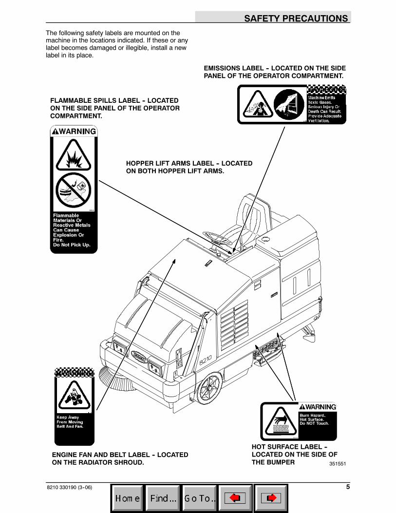
The following safety labels are mounted on themachine in the locations indicated. If these or anylabel becomes damaged or illegible, install a newlabel in its place.
ENGINE FAN AND BELT LABEL -- LOCATEDON THE RADIATOR SHROUD.
EMISSIONS LABEL -- LOCATED ON THE SIDEPANEL OF THE OPERATOR COMPARTMENT.
FLAMMABLE SPILLS LABEL -- LOCATEDON THE SIDE PANEL OF THE OPERATORCOMPARTMENT.
351551
HOPPER LIFT ARMS LABEL -- LOCATEDON BOTH HOPPER LIFT ARMS.
HOT SURFACE LABEL --LOCATED ON THE SIDE OFTHE BUMPER
SAFETY PRECAUTIONS
8210 330190 (9--05)6
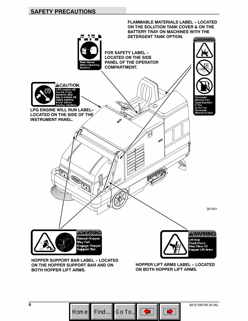
HOPPER LIFT ARMS LABEL -- LOCATEDON BOTH HOPPER LIFT ARMS.
HOPPER SUPPORT BAR LABEL -- LOCATEDON THE HOPPER SUPPORT BAR AND ONBOTH HOPPER LIFT ARMS.
351551
FLAMMABLE MATERIALS LABEL -- LOCATEDON THE SOLUTION TANK COVER & ON THEBATTERY TRAY ON MACHINES WITH THEDETERGENT TANK OPTION.
FOR SAFETY LABEL --LOCATED ON THE SIDEPANEL OF THE OPERATORCOMPARTMENT.
LPG ENGINE WILL RUN LABEL--LOCATED ON THE SIDE OF THEINSTRUMENT PANEL.

OPERATION
78210 330190 (1--98)
OPERATION
OPERATOR RESPONSIBILITY
- The operator’s responsibility is to take careof the daily maintenance and checkups ofthe machine to keep it in good workingcondition. The operator must inform theservice mechanic or supervisor when therequired maintenance intervals occur asstated in the MAINTENANCE section of thismanual.
- Read this manual carefully before operatingthis machine.
FOR SAFETY: Do not operate machine,unless operation manual is read andunderstood.
- Check the machine for shipping damage.Check to make sure machine is completeper shipping instructions.
- Keep your machine regularly maintained byfollowing the maintenance information in thismanual. We recommend taking advantageof a regularly scheduled service contractfrom your Tennant representative.
- Order parts and supplies directly from yourauthorized Tennant representative. Use theparts manual provided when ordering parts.
- After the first 50 hours of operation, followthe recommended procedures stated in theMAINTENANCE CHART.
07324

OPERATION
8210 330190 (6--04)8
MACHINE COMPONENTS
AB
C
D
E
F
H
JI
K
L
M
N
O
P
Q
G
351551A. Control panelB. Steering wheelC. Operator seatD. Engine coverE. Engine side doorF. Rear squeegeeG. Side squeegeeH. Sweeping brush access doorI. Hopper coverJ. Hopper dust filterK. Solution tankL. Recovery tankM. Main sweeping brushN. Side brushO. Scrub brushesP. Detergent tank (option)Q. Scrub head
OPERATION
98210 330190 (6--04)
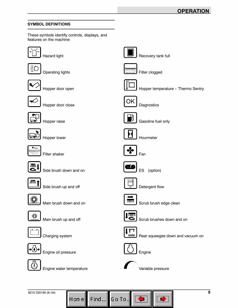
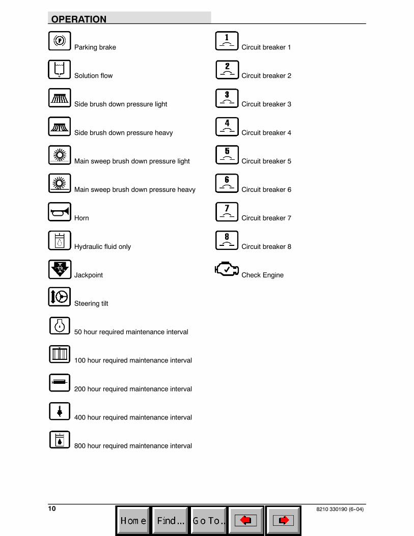
SYMBOL DEFINITIONS
These symbols identify controls, displays, andfeatures on the machine:
Hazard light Recovery tank full
Operating lights Filter clogged
Hopper door open Hopper temperature -- Thermo Sentry
Hopper door close Diagnostics
Hopper raise Gasoline fuel only
Hopper lower Hourmeter
Filter shaker Fan
Side brush down and on ES (option)
Side brush up and off Detergent flow
Main brush down and on Scrub brush edge clean
Main brush up and off Scrub brushes down and on
Charging system Rear squeegee down and vacuum on
Engine oil pressure Engine
Engine water temperature Variable pressure
OPERATION
8210 330190 (6--04)10
Parking brake Circuit breaker 1
Solution flow Circuit breaker 2
Side brush down pressure light Circuit breaker 3
Side brush down pressure heavy Circuit breaker 4
Main sweep brush down pressure light Circuit breaker 5
Main sweep brush down pressure heavy Circuit breaker 6
Horn Circuit breaker 7
Hydraulic fluid only Circuit breaker 8
Jackpoint Check Engine
Steering tilt
50 hour required maintenance interval
100 hour required maintenance interval
200 hour required maintenance interval
400 hour required maintenance interval
800 hour required maintenance interval
OPERATION
118210 330190 (3--06)
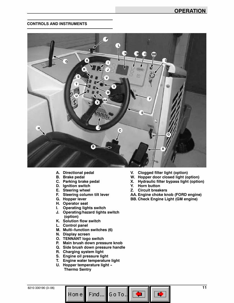
CONTROLS AND INSTRUMENTS
A
AA
Q
B
C
E
F
ZH
G
P
L
N M O
D
X
W
Y
V
J
IK
R
S
T
U
BB
A. Directional pedal V. Clogged filter light (option)B. Brake pedal W. Hopper door closed light (option)C. Parking brake pedal X. Hydraulic filter bypass light (option)D. Ignition switch Y. Horn buttonE. Steering wheel Z. Circuit breakersF. Steering column tilt lever AA. Engine choke knob (FORD engine)G. Hopper lever BB. Check Engine Light (GM engine)H. Operator seatI. Operating lights switchJ. Operating/hazard lights switch
(option)K. Solution flow switchL. Control panelM. Multi--function switches (6)N. Display screenO. TENNANT logo switchP. Main brush down pressure knobQ. Side brush down pressure handleR. Charging system lightS. Engine oil pressure lightT. Engine water temperature lightU. Hopper temperature light --
Thermo Sentry
OPERATION
8210 330190 (1--98)12
OPERATION OF CONTROLS
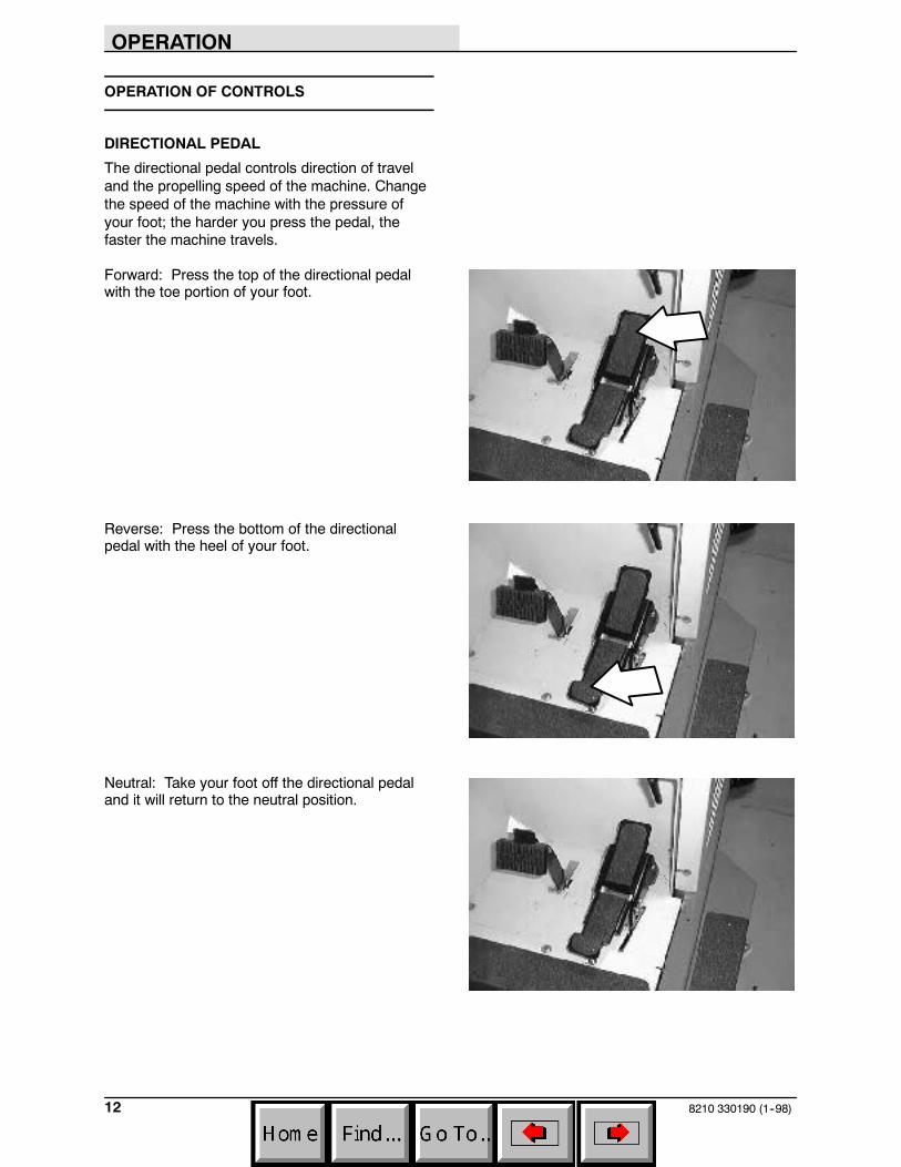
DIRECTIONAL PEDAL
The directional pedal controls direction of traveland the propelling speed of the machine. Changethe speed of the machine with the pressure ofyour foot; the harder you press the pedal, thefaster the machine travels.
Forward: Press the top of the directional pedalwith the toe portion of your foot.
Reverse: Press the bottom of the directionalpedal with the heel of your foot.
Neutral: Take your foot off the directional pedaland it will return to the neutral position.
OPERATION
138210 330190 (1--98)
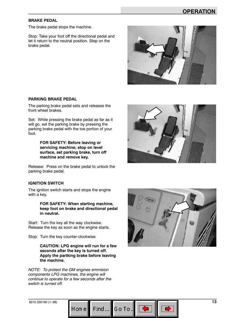
BRAKE PEDAL
The brake pedal stops the machine.
Stop: Take your foot off the directional pedal andlet it return to the neutral position. Step on thebrake pedal.
PARKING BRAKE PEDAL
The parking brake pedal sets and releases thefront wheel brakes.
Set: While pressing the brake pedal as far as itwill go, set the parking brake by pressing theparking brake pedal with the toe portion of yourfoot.
FOR SAFETY: Before leaving orservicing machine; stop on levelsurface, set parking brake, turn offmachine and remove key.
Release: Press on the brake pedal to unlock theparking brake pedal.
IGNITION SWITCH
The ignition switch starts and stops the enginewith a key.
FOR SAFETY: When starting machine,keep foot on brake and directional pedalin neutral.
Start: Turn the key all the way clockwise.Release the key as soon as the engine starts.
Stop: Turn the key counter-clockwise.
CAUTION: LPG engine will run for a fewseconds after the key is turned off.Apply the partking brake before leavingthe machine.
NOTE: To protect the GM engines emmisioncomponents LPG machines, the engine willcontinue to operate for a few seconds after theswitch is turned off.
OPERATION
8210 330190 (6--04)14
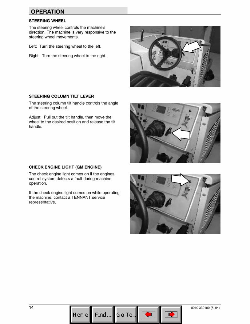
STEERING WHEEL
The steering wheel controls the machine’sdirection. The machine is very responsive to thesteering wheel movements.
Left: Turn the steering wheel to the left.
Right: Turn the steering wheel to the right.
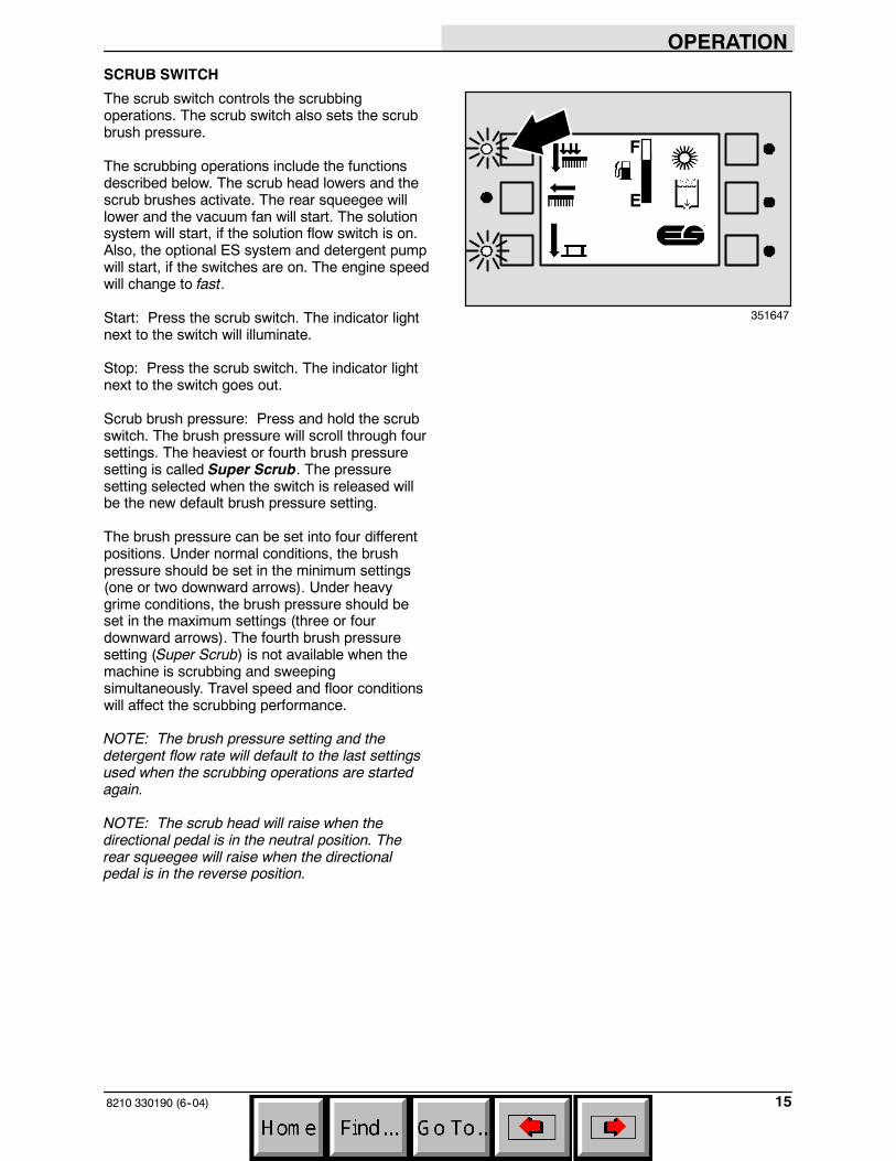
STEERING COLUMN TILT LEVER
The steering column tilt handle controls the angleof the steering wheel.
Adjust: Pull out the tilt handle, then move thewheel to the desired position and release the tilthandle.
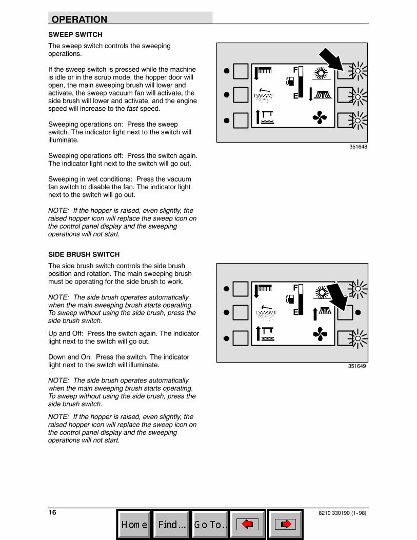
CHECK ENGINE LIGHT (GM ENGINE)
The check engine light comes on if the enginescontrol system detects a fault during machineoperation.
If the check engine light comes on while operatingthe machine, contact a TENNANT servicerepresentative.
OPERATION
158210 330190 (6--04)
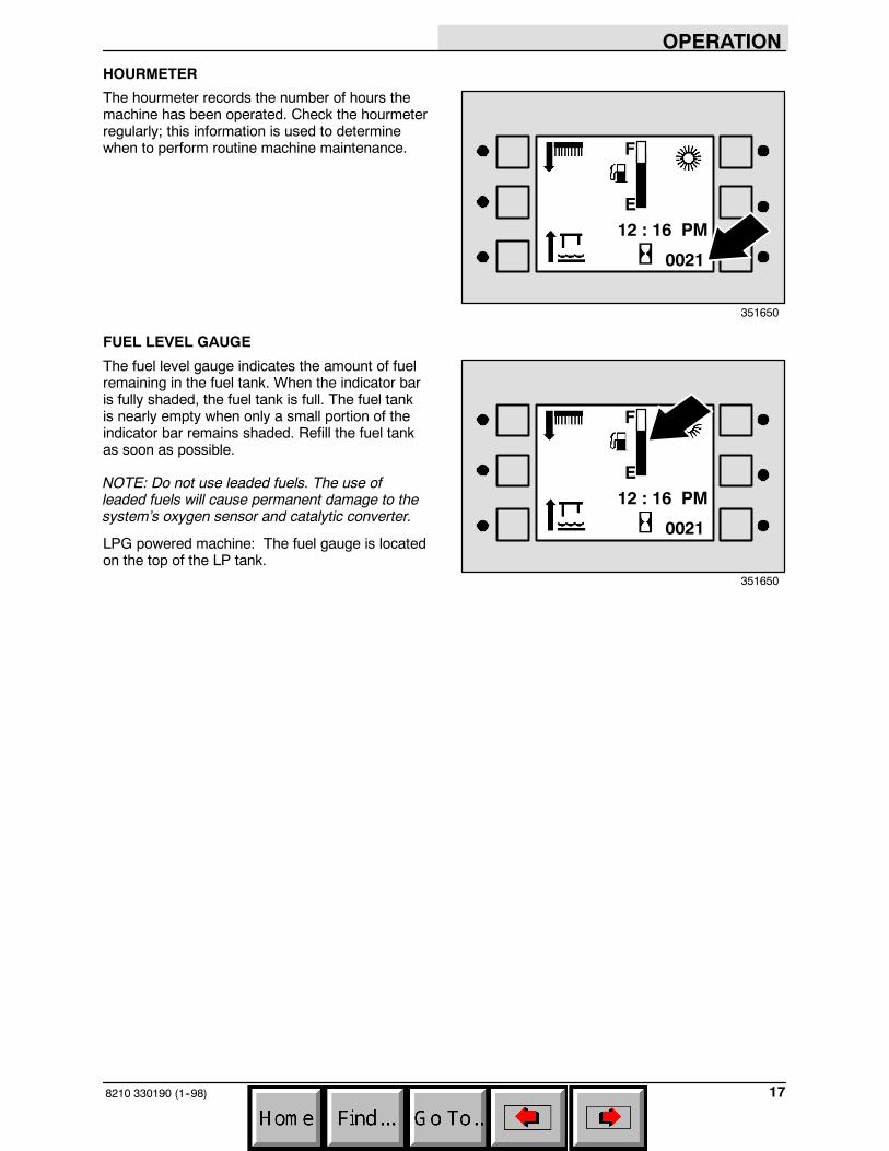
SCRUB SWITCH
The scrub switch controls the scrubbingoperations. The scrub switch also sets the scrubbrush pressure.
The scrubbing operations include the functionsdescribed below. The scrub head lowers and thescrub brushes activate. The rear squeegee willlower and the vacuum fan will start. The solutionsystem will start, if the solution flow switch is on.Also, the optional ES system and detergent pumpwill start, if the switches are on. The engine speedwill change to fast.
Start: Press the scrub switch. The indicator lightnext to the switch will illuminate.
Stop: Press the scrub switch. The indicator lightnext to the switch goes out.
Scrub brush pressure: Press and hold the scrubswitch. The brush pressure will scroll through foursettings. The heaviest or fourth brush pressuresetting is called Super Scrub. The pressuresetting selected when the switch is released willbe the new default brush pressure setting.
The brush pressure can be set into four differentpositions. Under normal conditions, the brushpressure should be set in the minimum settings(one or two downward arrows). Under heavygrime conditions, the brush pressure should beset in the maximum settings (three or fourdownward arrows). The fourth brush pressuresetting (Super Scrub) is not available when themachine is scrubbing and sweepingsimultaneously. Travel speed and floor conditionswill affect the scrubbing performance.
NOTE: The brush pressure setting and thedetergent flow rate will default to the last settingsused when the scrubbing operations are startedagain.
NOTE: The scrub head will raise when thedirectional pedal is in the neutral position. Therear squeegee will raise when the directionalpedal is in the reverse position.
F
E
351647
OPERATION
8210 330190 (1--98)16
SWEEP SWITCH
The sweep switch controls the sweepingoperations.
If the sweep switch is pressed while the machineis idle or in the scrub mode, the hopper door willopen, the main sweeping brush will lower andactivate, the sweep vacuum fan will activate, theside brush will lower and activate, and the enginespeed will increase to the fast speed.
Sweeping operations on: Press the sweepswitch. The indicator light next to the switch willilluminate.
Sweeping operations off: Press the switch again.The indicator light next to the switch will go out.
Sweeping in wet conditions: Press the vacuumfan switch to disable the fan. The indicator lightnext to the switch will go out.
NOTE: If the hopper is raised, even slightly, theraised hopper icon will replace the sweep icon onthe control panel display and the sweepingoperations will not start.
SIDE BRUSH SWITCH
The side brush switch controls the side brushposition and rotation. The main sweeping brushmust be operating for the side brush to work.
NOTE: The side brush operates automaticallywhen the main sweeping brush starts operating.To sweep without using the side brush, press theside brush switch.
Up and Off: Press the switch again. The indicatorlight next to the switch will go out.
Down and On: Press the switch. The indicatorlight next to the switch will illuminate.
NOTE: The side brush operates automaticallywhen the main sweeping brush starts operating.To sweep without using the side brush, press theside brush switch.
NOTE: If the hopper is raised, even slightly, theraised hopper icon will replace the sweep icon onthe control panel display and the sweepingoperations will not start.
F
E
351648
F
E
351649
OPERATION
178210 330190 (1--98)
HOURMETER
The hourmeter records the number of hours themachine has been operated. Check the hourmeterregularly; this information is used to determinewhen to perform routine machine maintenance.
FUEL LEVEL GAUGE
The fuel level gauge indicates the amount of fuelremaining in the fuel tank. When the indicator baris fully shaded, the fuel tank is full. The fuel tankis nearly empty when only a small portion of theindicator bar remains shaded. Refill the fuel tankas soon as possible.
NOTE: Do not use leaded fuels. The use ofleaded fuels will cause permanent damage to thesystem’s oxygen sensor and catalytic converter.
LPG powered machine: The fuel gauge is locatedon the top of the LP tank.
F
E12 : 16 PM
0021
351650
F
E12 : 16 PM
0021
351650
OPERATION
8210 330190 (1--98)18
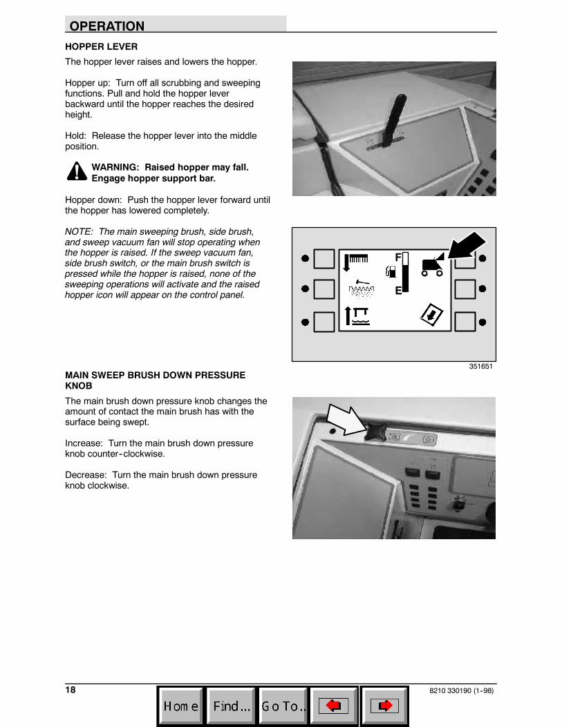
HOPPER LEVER
The hopper lever raises and lowers the hopper.
Hopper up: Turn off all scrubbing and sweepingfunctions. Pull and hold the hopper leverbackward until the hopper reaches the desiredheight.
Hold: Release the hopper lever into the middleposition.
WARNING: Raised hopper may fall.Engage hopper support bar.
Hopper down: Push the hopper lever forward untilthe hopper has lowered completely.
NOTE: The main sweeping brush, side brush,and sweep vacuum fan will stop operating whenthe hopper is raised. If the sweep vacuum fan,side brush switch, or the main brush switch ispressed while the hopper is raised, none of thesweeping operations will activate and the raisedhopper icon will appear on the control panel.
MAIN SWEEP BRUSH DOWN PRESSUREKNOB
The main brush down pressure knob changes theamount of contact the main brush has with thesurface being swept.
Increase: Turn the main brush down pressureknob counter--clockwise.
Decrease: Turn the main brush down pressureknob clockwise.
F
E
351651
OPERATION
198210 330190 (6--04)
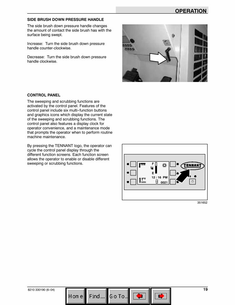
SIDE BRUSH DOWN PRESSURE HANDLE
The side brush down pressure handle changesthe amount of contact the side brush has with thesurface being swept.
Increase: Turn the side brush down pressurehandle counter-clockwise.
Decrease: Turn the side brush down pressurehandle clockwise.
CONTROL PANEL
The sweeping and scrubbing functions areactivated by the control panel. Features of thecontrol panel include six multi--function buttonsand graphics icons which display the current stateof the sweeping and scrubbing functions. Thecontrol panel also features a display clock foroperator convenience, and a maintenance modethat prompts the operator when to perform routinemachine maintenance.
By pressing the TENNANT logo, the operator cancycle the control panel display through thedifferent function screens. Each function screenallows the operator to enable or disable differentsweeping or scrubbing functions. F
E12 : 16 PM
0021
351652
OPERATION
8210 330190 (1--98)20
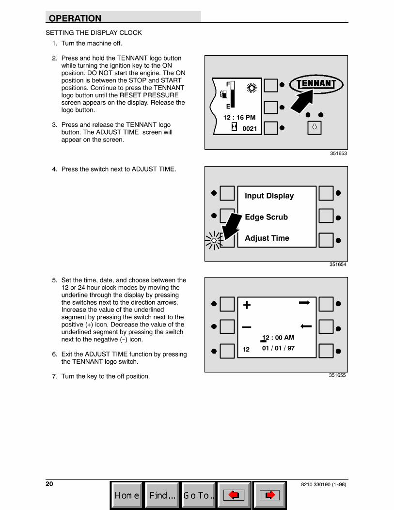
SETTING THE DISPLAY CLOCK
1. Turn the machine off.
2. Press and hold the TENNANT logo buttonwhile turning the ignition key to the ONposition. DO NOT start the engine. The ONposition is between the STOP and STARTpositions. Continue to press the TENNANTlogo button until the RESET PRESSUREscreen appears on the display. Release thelogo button.
3. Press and release the TENNANT logobutton. The ADJUST TIME screen willappear on the screen.
4. Press the switch next to ADJUST TIME.
5. Set the time, date, and choose between the12 or 24 hour clock modes by moving theunderline through the display by pressingthe switches next to the direction arrows.Increase the value of the underlinedsegment by pressing the switch next to thepositive (+) icon. Decrease the value of theunderlined segment by pressing the switchnext to the negative (--) icon.
6. Exit the ADJUST TIME function by pressingthe TENNANT logo switch.
7. Turn the key to the off position.
F
E
12 : 16 PM
0021
351653
Input Display
Adjust Time
Edge Scrub
351654
12 01 / 01 / 97
12 : 00 AM--
+_
351655
OPERATION
218210 330190 (1--98)
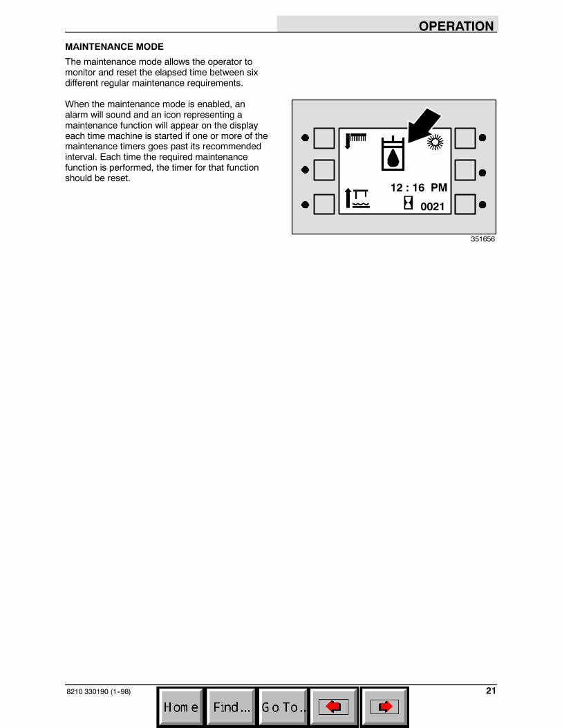
MAINTENANCE MODE
The maintenance mode allows the operator tomonitor and reset the elapsed time between sixdifferent regular maintenance requirements.
When the maintenance mode is enabled, analarm will sound and an icon representing amaintenance function will appear on the displayeach time machine is started if one or more of themaintenance timers goes past its recommendedinterval. Each time the required maintenancefunction is performed, the timer for that functionshould be reset.
12 : 16 PM
0021
351656
OPERATION
8210 330190 (1--98)22
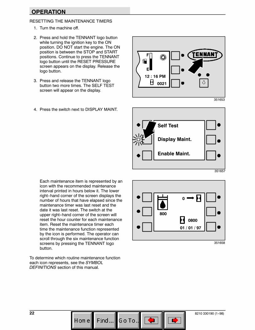
RESETTING THE MAINTENANCE TIMERS
1. Turn the machine off.
2. Press and hold the TENNANT logo buttonwhile turning the ignition key to the ONposition. DO NOT start the engine. The ONposition is between the STOP and STARTpositions. Continue to press the TENNANTlogo button until the RESET PRESSUREscreen appears on the display. Release thelogo button.
3. Press and release the TENNANT logobutton two more times. The SELF TESTscreen will appear on the display.
4. Press the switch next to DISPLAY MAINT.
Each maintenance item is represented by anicon with the recommended maintenanceinterval printed in hours below it. The lowerright--hand corner of the screen displays thenumber of hours that have elapsed since themaintenance timer was last reset and thedate it was last reset. The switch at theupper right--hand corner of the screen willreset the hour counter for each maintenanceitem. Reset the maintenance timer eachtime the maintenance function representedby the icon is performed. The operator canscroll through the six maintenance functionscreens by pressing the TENNANT logobutton.
To determine which routine maintenance functioneach icon represents, see the SYMBOLDEFINITIONS section of this manual.
F
E
12 : 16 PM
0021
351653
Self Test
Display Maint.
Enable Maint.
351657
01 / 01 / 97
800
0
0800
351658
OPERATION
238210 330190 (1--98)
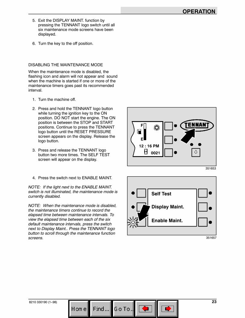
5. Exit the DISPLAY MAINT. function bypressing the TENNANT logo switch until allsix maintenance mode screens have beendisplayed.
6. Turn the key to the off position.
DISABLING THE MAINTENANCE MODE
When the maintenance mode is disabled, theflashing icon and alarm will not appear and soundwhen the machine is started if one or more of themaintenance timers goes past its recommendedinterval.
1. Turn the machine off.
2. Press and hold the TENNANT logo buttonwhile turning the ignition key to the ONposition. DO NOT start the engine. The ONposition is between the STOP and STARTpositions. Continue to press the TENNANTlogo button until the RESET PRESSUREscreen appears on the display. Release thelogo button.
3. Press and release the TENNANT logobutton two more times. The SELF TESTscreen will appear on the display.
4. Press the switch next to ENABLE MAINT.
NOTE: If the light next to the ENABLE MAINT.switch is not illuminated, the maintenance mode iscurrently disabled.
NOTE: When the maintenance mode is disabled,the maintenance timers continue to record theelapsed time between maintenance intervals. Toview the elapsed time between each of the sixdefault maintenance intervals, press the switchnext to Display Maint.. Press the TENNANT logobutton to scroll through the maintenance functionscreens.
F
E
12 : 16 PM
0021
351653
Self Test
Display Maint.
Enable Maint.
351657
OPERATION
8210 330190 (1--98)24
OPERATING LIGHTS SWITCH
The operating lights switch powers the headlightsand taillights on and off.
On: Press the top of the operating lights switch.
Off: Press the bottom of the operating lightsswitch.
OPERATING/HAZARD LIGHT SWITCH(OPTION)
The operating/hazard light switch powers theheadlights and taillights, and the revolving hazardlight (option) on and off.
Operating lights on: Press the top of the hazardlight switch.
Operating lights/Hazard light (option) on: Pressthe bottom of the hazard light switch.
All lights off: Set the the hazard light switch in themiddle position.
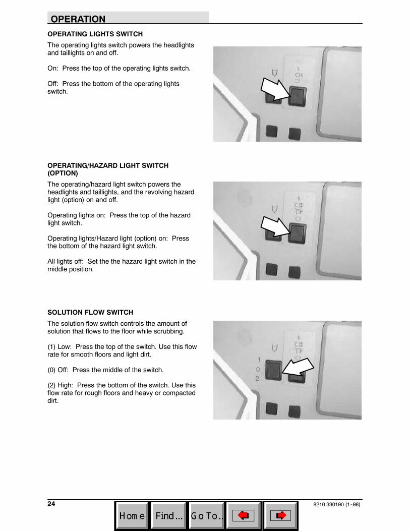
SOLUTION FLOW SWITCH
The solution flow switch controls the amount ofsolution that flows to the floor while scrubbing.
(1) Low: Press the top of the switch. Use this flowrate for smooth floors and light dirt.
(0) Off: Press the middle of the switch.
(2) High: Press the bottom of the switch. Use thisflow rate for rough floors and heavy or compacteddirt.
102

OPERATION
258210 330190 (6--04)
MANUAL FLOW VALVE
The machine is equipped with a manuallyadjustable solution flow valve that is located onthe right side of the scrubhead. The valve can beadjusted to dispense either more or less solution.Contact your TENNANT representative withsolution flow rate questions.
Maximum flow: Turn the flow lever to thehorizontal position.
Minimum flow: Turn the flow lever to the verticalposition.
ENGINE CHOKE KNOB (FORD ENGINE)
The engine choke knob controls the engine chokeon FORD gasoline powered machines.
On: For cold starting, pull the engine choke knobout.
Off: Push the engine choke knob in.
SWEEP VACUUM FAN SWITCH
The sweep vacuum fan switch starts and stopsthe sweep vacuum fan. Do not operate thevacuum fan when sweeping in wet conditions.
Start: Press the switch. The indicator next to theswitch will illuminate.
Stop: Press the switch. The indicator light next tothe switch will go out.
NOTE: The sweep vacuum fan activatesautomatically when the main sweeping brushstarts operating. The sweep vacuum fan will notactivate unless the main sweeping brush isoperating.
NOTE: The sweep vacuum fan will not start if thehopper is raised, even slightly. If the sweepvacuum fan switch is pressed while the hopper israised, the sweep vacuum will not start and theraised hopper icon will appear on the controlpanel.
F
E
351648
OPERATION
8210 330190 (1--98)26
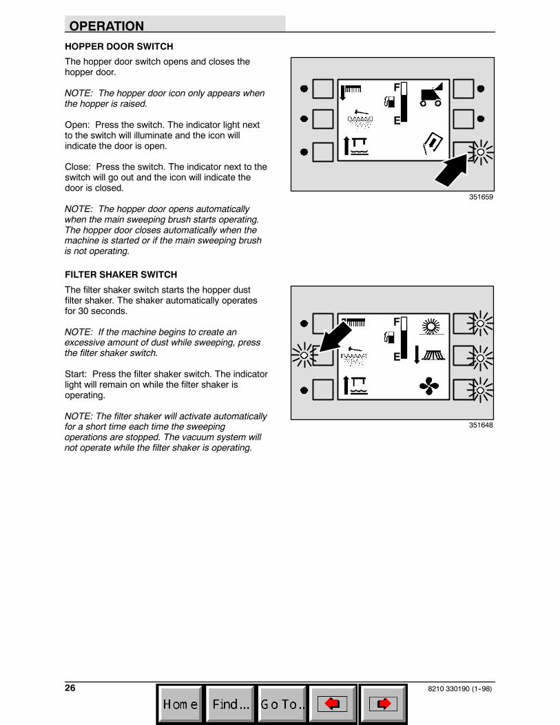
HOPPER DOOR SWITCH
The hopper door switch opens and closes thehopper door.
NOTE: The hopper door icon only appears whenthe hopper is raised.
Open: Press the switch. The indicator light nextto the switch will illuminate and the icon willindicate the door is open.
Close: Press the switch. The indicator next to theswitch will go out and the icon will indicate thedoor is closed.
NOTE: The hopper door opens automaticallywhen the main sweeping brush starts operating.The hopper door closes automatically when themachine is started or if the main sweeping brushis not operating.
FILTER SHAKER SWITCH
The filter shaker switch starts the hopper dustfilter shaker. The shaker automatically operatesfor 30 seconds.
NOTE: If the machine begins to create anexcessive amount of dust while sweeping, pressthe filter shaker switch.
Start: Press the filter shaker switch. The indicatorlight will remain on while the filter shaker isoperating.
NOTE: The filter shaker will activate automaticallyfor a short time each time the sweepingoperations are stopped. The vacuum system willnot operate while the filter shaker is operating.
F
E
351659
F
E
351648
OPERATION
278210 330190 (1--98)
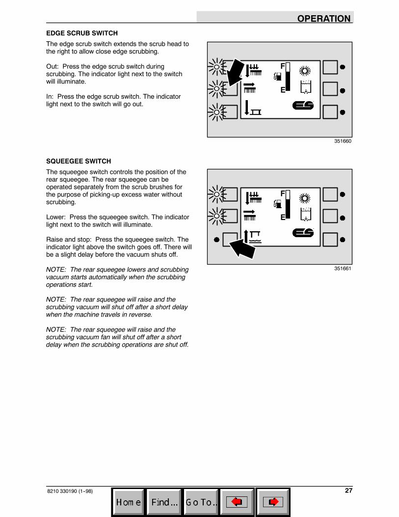
EDGE SCRUB SWITCH
The edge scrub switch extends the scrub head tothe right to allow close edge scrubbing.
Out: Press the edge scrub switch duringscrubbing. The indicator light next to the switchwill illuminate.
In: Press the edge scrub switch. The indicatorlight next to the switch will go out.
SQUEEGEE SWITCH
The squeegee switch controls the position of therear squeegee. The rear squeegee can beoperated separately from the scrub brushes forthe purpose of picking-up excess water withoutscrubbing.
Lower: Press the squeegee switch. The indicatorlight next to the switch will illuminate.
Raise and stop: Press the squeegee switch. Theindicator light above the switch goes off. There willbe a slight delay before the vacuum shuts off.
NOTE: The rear squeegee lowers and scrubbingvacuum starts automatically when the scrubbingoperations start.
NOTE: The rear squeegee will raise and thescrubbing vacuum will shut off after a short delaywhen the machine travels in reverse.
NOTE: The rear squeegee will raise and thescrubbing vacuum fan will shut off after a shortdelay when the scrubbing operations are shut off.
F
E
351660
F
E
351661
OPERATION
8210 330190 (6--04)28
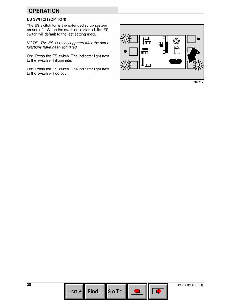
ES SWITCH (OPTION)
The ES switch turns the extended scrub systemon and off . When the machine is started, the ESswitch will default to the last setting used.
NOTE: The ES icon only appears after the scrubfunctions have been activated.
On: Press the ES switch. The indicator light nextto the switch will illuminate.
Off: Press the ES switch. The indicator light nextto the switch will go out.
F
E
351647

OPERATION
298210 330190 (1--98)
DETERGENT PUMP SWITCH (OPTION)
The detergent switch controls the amount ofdetergent that flows to the floor while scrubbing.When the machine is started, the detergent pumpswitch will default to the last setting used.
NOTE: The detergent icon only appears after thescrub functions have been activated.
NOTE: The detergent pump switch will notactivate unless the main scrub brushes are activeand the solution switch is in the high or lowposition.
High: Press and hold the detergent pump switchuntil two downward pointing arrows appear on theicon next to the switch. Release the switch.
Low: Press and hold the detergent pump switchuntil one downward pointing arrow appears on theicon next to the switch. Release the switch.
Off: Press and release the detergent pumpswitch.
ENGINE SPEED SWITCH
The engine speed switch controls the enginegoverned speed. When one indicator light abovethe switch is illuminated, the engine is in idlespeed. When two indicator lights above the switchare illuminated, the engine is in fast speed.
NOTE: The engine will run automatically in fastspeed while scrubbing or sweeping, or bothsimultaneously.
Idle speed (one indicator lit): The engine willautomatically start in idle speed. To switch to fastengine speed, press the engine speed switch.
Fast speed (two indicators lit): Press the enginespeed switch until both indicators are lit. Use thisspeed is for transporting, sweeping, andscrubbing. To return the engine to idle speed fromthe fast engine speed, press the engine speedswitch.
NOTE: All sweeping and scrubbing functionswhile stop automatically if idle speed is selectedwhile in fast engine speed.
F
E
351647
F
E
12 : 16 PM
0021
351653
OPERATION
8210 330190 (11--98)30
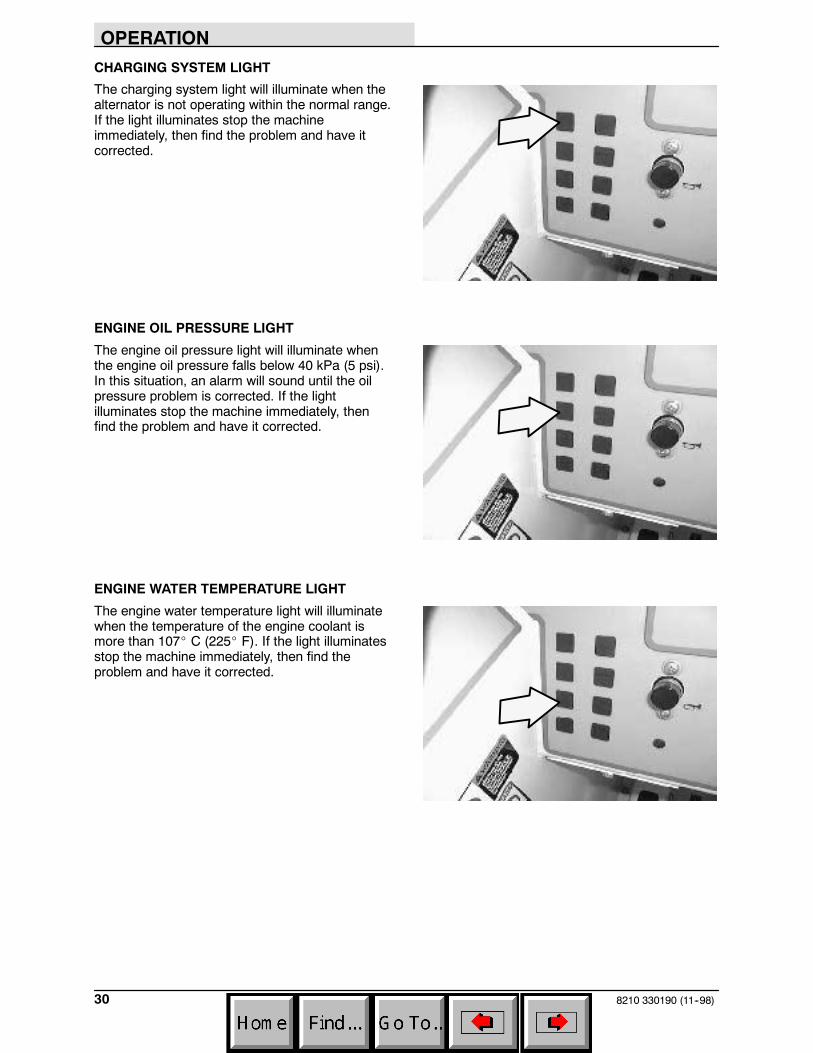
CHARGING SYSTEM LIGHT
The charging system light will illuminate when thealternator is not operating within the normal range.If the light illuminates stop the machineimmediately, then find the problem and have itcorrected.
ENGINE OIL PRESSURE LIGHT
The engine oil pressure light will illuminate whenthe engine oil pressure falls below 40 kPa (5 psi).In this situation, an alarm will sound until the oilpressure problem is corrected. If the lightilluminates stop the machine immediately, thenfind the problem and have it corrected.
ENGINE WATER TEMPERATURE LIGHT
The engine water temperature light will illuminatewhen the temperature of the engine coolant ismore than 107_ C (225_ F). If the light illuminatesstop the machine immediately, then find theproblem and have it corrected.
OPERATION
318210 330190 (6--04)
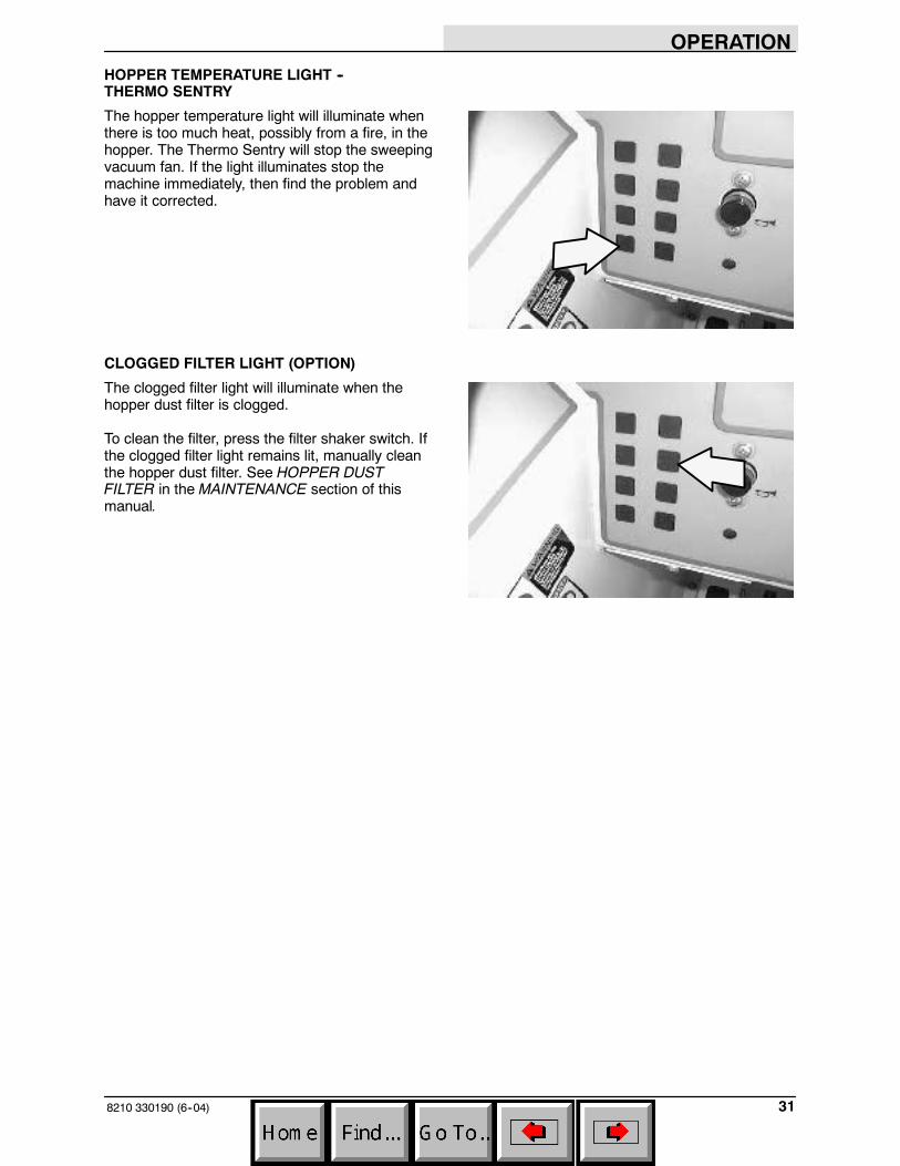
HOPPER TEMPERATURE LIGHT --THERMO SENTRY
The hopper temperature light will illuminate whenthere is too much heat, possibly from a fire, in thehopper. The Thermo Sentry will stop the sweepingvacuum fan. If the light illuminates stop themachine immediately, then find the problem andhave it corrected.
CLOGGED FILTER LIGHT (OPTION)
The clogged filter light will illuminate when thehopper dust filter is clogged.
To clean the filter, press the filter shaker switch. Ifthe clogged filter light remains lit, manually cleanthe hopper dust filter. See HOPPER DUSTFILTER in the MAINTENANCE section of thismanual.

OPERATION
8210 330190 (1--98)32
HOPPER DOOR CLOSED LIGHT (OPTION)
The hopper door closed light will illuminate whenthe hopper door is closed.
Make sure the the hooper door is open (the lightwill be out), while sweeping.
HYDRAULIC FILTER BYPASS LIGHT (OPTION)
The hydraulic filter bypass light will illuminatewhen the hydraulic filter becomes clogged. If thelight illuminates stop the machine immediately,then change the hydraulic filter and hydraulic fluidas soon as possible.
HORN BUTTON
The horn button operates the horn.
Sound: Press the button.
OPERATION
338210 330190 (6--04)
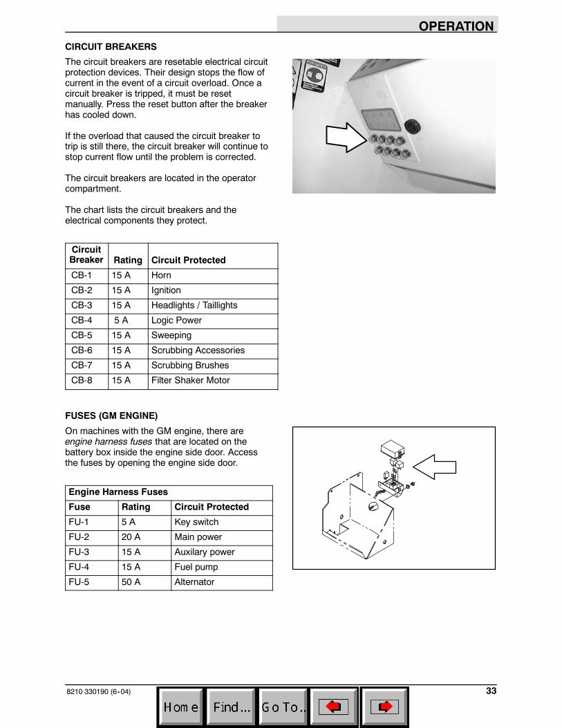
CIRCUIT BREAKERS
The circuit breakers are resetable electrical circuitprotection devices. Their design stops the flow ofcurrent in the event of a circuit overload. Once acircuit breaker is tripped, it must be resetmanually. Press the reset button after the breakerhas cooled down.
If the overload that caused the circuit breaker totrip is still there, the circuit breaker will continue tostop current flow until the problem is corrected.
The circuit breakers are located in the operatorcompartment.
The chart lists the circuit breakers and theelectrical components they protect.
CircuitBreaker Rating Circuit Protected
CB-1 15 A Horn
CB-2 15 A Ignition
CB-3 15 A Headlights / Taillights
CB-4 5 A Logic Power
CB-5 15 A Sweeping
CB-6 15 A Scrubbing Accessories
CB-7 15 A Scrubbing Brushes
CB-8 15 A Filter Shaker Motor
FUSES (GM ENGINE)
On machines with the GM engine, there areengine harness fuses that are located on thebattery box inside the engine side door. Accessthe fuses by opening the engine side door.
Engine Harness Fuses
Fuse Rating Circuit Protected
FU-1 5 A Key switch
FU-2 20 A Main power
FU-3 15 A Auxilary power
FU-4 15 A Fuel pump
FU-5 50 A Alternator
OPERATION
8210 330190 (1--98)34
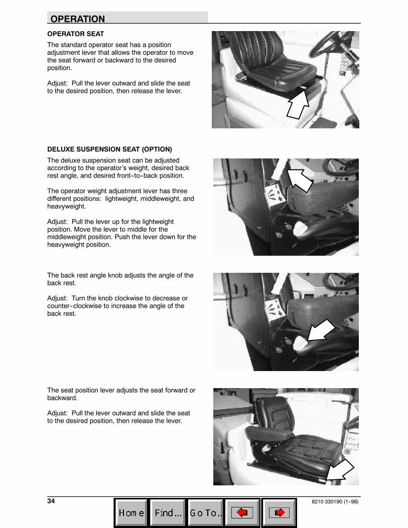
OPERATOR SEAT
The standard operator seat has a positionadjustment lever that allows the operator to movethe seat forward or backward to the desiredposition.
Adjust: Pull the lever outward and slide the seatto the desired position, then release the lever.
DELUXE SUSPENSION SEAT (OPTION)
The deluxe suspension seat can be adjustedaccording to the operator’s weight, desired backrest angle, and desired front--to--back position.
The operator weight adjustment lever has threedifferent positions: lightweight, middleweight, andheavyweight.
Adjust: Pull the lever up for the lightweightposition. Move the lever to middle for themiddleweight position. Push the lever down for theheavyweight position.
The back rest angle knob adjusts the angle of theback rest.
Adjust: Turn the knob clockwise to decrease orcounter--clockwise to increase the angle of theback rest.
The seat position lever adjusts the seat forward orbackward.
Adjust: Pull the lever outward and slide the seatto the desired position, then release the lever.

OPERATION
358210 330190 (1--98)
HOPPER SUPPORT BAR
The hopper support bar is located on theoperator’s side of the hopper. The hopper supportbar holds the hopper in the raised position to allowwork under the hopper. DO NOT rely on themachine hydraulic system to keep the hopperraised.
WARNING: Raised hopper may fall.Engage hopper support bar.
ENGINE COVER GAS SPRING
The engine cover gas spring is locatedunderneath the engine cover. The gas springholds the engine cover in the raised position toallow work on the engine.
To close the engine cover, push the lower portionof the gas spring in line with the top portion, andpush the engine cover downward.
LATCHES
The solution tank cover and the side and topengine doors are secured with latches.
Open: Press the raised part of the latch.
Close: Press the flat part of the latch.
OPERATION
8210 330190 (6--04)36
HOW THE MACHINE WORKS
The steering wheel controls the direction ofmachine travel. The directional pedal controls thespeed and forward/reverse direction. The brakepedal slows and stops the machine.
The side brush sweeps debris into the path of themain sweeping brush. The main brush sweepsdebris from the floor into the hopper. The vacuumsystem pulls dust and air through the hopper andthe hopper dust filter.
Water and detergent from the solution tank flow tothe floor through a solution valve to the scrubbrushes. The brushes scrub the floor. As themachine is moved forward the squeegee wipesthe dirty solution off the floor, which is then pickedup and drawn into the recovery tank.
When using the ES mode, the dirty solution in therecovery tank is filtered and returned to thesolution tank to be reused.
When sweeping and scrubbing is finished, cleanthe hopper dust filter, empty the hopper, and drainand clean the recovery tank. If using the ESsystem, drain and clean the solution tank, andclean the ES filter.

OPERATION
378210 330190 (6--03)
PRE-OPERATION CHECKLIST
- Check the engine oil level.
- Check the engine coolant level.
- Check the radiator and hydraulic cooler finsfor debris.
- Check the hydraulic fluid level
- Check the air filter indicator.
- Check the skirts and seals for damage andwear.
- Check the condition of the sweeping andscrubbing brushes. Remove any string,banding, plastic wrap, or other debriswrapped around them.
- Check the sweeping brush patterns foradjustment.
- Check the condition of the hopper dust filterand seals. Clean as required.
- Check the tank cover seals for damage andwear.
- Clean the vacuum fan inlet filter.
- Check the squeegees for damage, wear andfor deflection adjustment.
- Check the vacuum hose for debris orblockage.
- ES machines; check the detergent tanklevel.
- Drain and clean the recovery tank.
- ES machines; drain and clean the solutiontank and ES filter. Rinse level sensors.
- Check the brakes and steering for properoperation.
- Check the fuel level
- Empty the debris hopper.
- Check the service records to determinemaintenance requirements.
OPERATION
8210 330190 (1--98)38
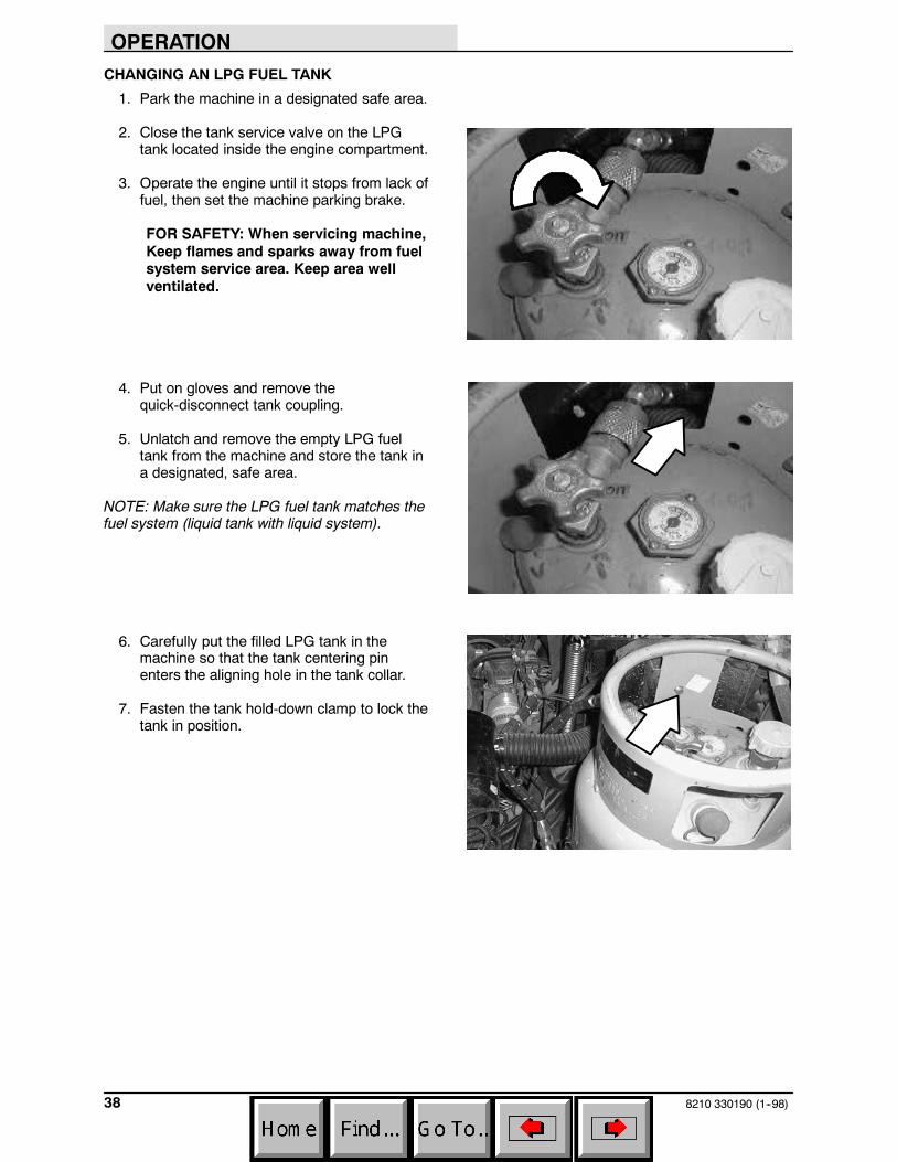
CHANGING AN LPG FUEL TANK
1. Park the machine in a designated safe area.
2. Close the tank service valve on the LPGtank located inside the engine compartment.
3. Operate the engine until it stops from lack offuel, then set the machine parking brake.
FOR SAFETY: When servicing machine,Keep flames and sparks away from fuelsystem service area. Keep area wellventilated.
4. Put on gloves and remove thequick-disconnect tank coupling.
5. Unlatch and remove the empty LPG fueltank from the machine and store the tank ina designated, safe area.
NOTE: Make sure the LPG fuel tank matches thefuel system (liquid tank with liquid system).
6. Carefully put the filled LPG tank in themachine so that the tank centering pinenters the aligning hole in the tank collar.
7. Fasten the tank hold-down clamp to lock thetank in position.
OPERATION
398210 330190 (1--98)
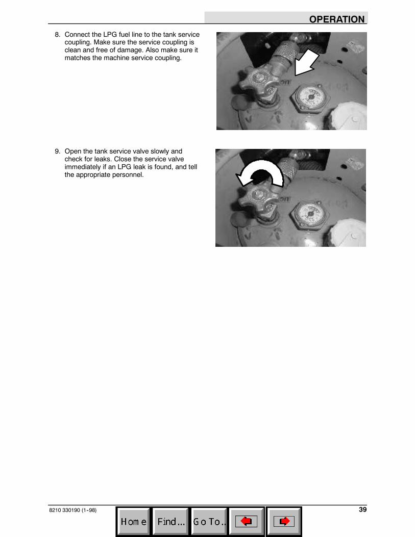
8. Connect the LPG fuel line to the tank servicecoupling. Make sure the service coupling isclean and free of damage. Also make sure itmatches the machine service coupling.
9. Open the tank service valve slowly andcheck for leaks. Close the service valveimmediately if an LPG leak is found, and tellthe appropriate personnel.

OPERATION
8210 330190 (1--98)40
STARTING THE MACHINE
1. LPG powered machines: Open the liquidservice valve slowly.
NOTE: Opening the service valve too quickly maycause the service check valve to stop the flow ofLPG fuel. If the check valve stops the fuel flow,close the service valve, wait a few seconds andopen the valve slowly again.
2. You must be in the operator’s seat with thedirectional pedal in neutral, and your foot onthe brake pedal or with the parking brakeset.
FOR SAFETY: When starting machine,keep foot on brake and directional pedalin neutral.
3. Ford gasoline powered machines: Pull outthe choke knob when the engine is cold.Push in the choke knob after the engine isrunning smoothly.

OPERATION
418210 330190 (1--98)
4. Turn the ignition switch key clockwise untilthe engine starts.
NOTE: Do not operate the starter motor for morethan 10 seconds at a time or after the engine hasstarted. Allow the starter to cool between startingattempts or damage to the starter motor mayoccur.
5. Allow the engine and hydraulic system towarm up three to five minutes.
WARNING: Engine emits toxic gases.Severe respiratory damage orasphyxiation can result. Provideadequate ventilation. Consult with yourregulatory authorities for exposurelimits. Keep engine properly tuned.
6. Release the machine parking brake.
7. Drive the machine to the area to be cleaned.

OPERATION
8210 330190 (1--98)42
SWEEPING, SCRUBBING, AND BRUSHINFORMATION
Pick up oversized debris before sweeping. Flattenor remove bulky cartons from aisles beforesweeping. Pick up pieces of wire, twine, string, oranything that could become entangled in thebrush or brush plugs.
Plan the sweeping and scrubbing in advance. Tryto arrange long runs with minimum stopping andstarting. Sweep debris from very narrow aislesinto main aisles ahead of time. Do an entire flooror section at one time. Drive as straight aspossible. Overlap the brush paths. Avoid bumpinginto posts or scraping the sides of the machine.
Avoid turning the steering wheel abruptly, exceptin emergencies. The machine is very responsiveto the movement of the steering wheel.
Adjust the machine speed, scrub brush pressure,and detergent and solution flow as required whenscrubbing. Use the minimum scrub brushpressure and solution flow for the best scrubbingresults. Machines with the edge clean option havethe ability to scrub against walls and edges.
When the recovery tank is almost full, therecovery tank full indicator will appear on thedisplay screen and blink for almost a minutebefore the scrubbing system shuts off. Therecovery tank will have to be drained and cleaned.Refill the solution tank with clean water anddetergent and continue cleaning.
For best results, use the correct brush type foryour sweeping and scrubbing application. Thefollowing are recommendations for mainsweeping, scrubbing, and side brush applications.
Polypropylene 8-double row main sweepbrush -- Superior pick-up of sand, gravel, andpaper litter. Polypropylene retains its stiffnesswhen wet, and can be used indoors or out withequal performance. Not recommended forhigh-temperature debris.
Polypropylene and Wire 8-double row mainsweep brush -- The wire bristles loosen slightlypacked soilage and heavier debris. Thepolypropylene bristles sweep up the debris withexcellent hopper loading.
OPERATION
438210 330190 (1--98)
Polyester 8-double row main sweep brush --Polyester combines the durability of nylon with themoisture resistance of polypropylene.
Polyester 24-row main sweep brush --Polyester combines the durability of nylon with themoisture resistance of polypropylene. This highdensity brush is recommended for applicationsthat sweep heavy accumulations of fine dust,sand, or other similar material.
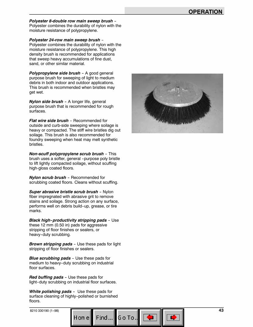
Polypropylene side brush -- A good generalpurpose brush for sweeping of light to mediumdebris in both indoor and outdoor applications.This brush is recommended when bristles mayget wet.
Nylon side brush -- A longer life, generalpurpose brush that is recommended for roughsurfaces.
Flat wire side brush -- Recommended foroutside and curb-side sweeping where soilage isheavy or compacted. The stiff wire bristles dig outsoilage. This brush is also recommended forfoundry sweeping when heat may melt syntheticbristles.
Non-scuff polypropylene scrub brush -- Thisbrush uses a softer, general --purpose poly bristleto lift lightly compacted soilage, without scuffinghigh-gloss coated floors.
Nylon scrub brush -- Recommended forscrubbing coated floors. Cleans without scuffing.
Super abrasive bristle scrub brush -- Nylonfiber impregnated with abrasive grit to removestains and soilage. Strong action on any surface,performs well on debris build--up, grease, or tiremarks.
Black high-productivity stripping pads -- Usethese 12 mm (0.50 in) pads for aggressivestripping of floor finishes or sealers, orheavy--duty scrubbing.
Brown stripping pads -- Use these pads for lightstripping of floor finishes or sealers.
Blue scrubbing pads -- Use these pads formedium to heavy--duty scrubbing on industrialfloor surfaces.
Red buffing pads -- Use these pads forlight--duty scrubbing on industrial floor surfaces.
White polishing pads -- Use these pads forsurface cleaning of highly--polished or burnishedfloors.

OPERATION
8210 330190 (1--98)44
SWEEPING
1. Start the engine.
2. Press the sweep switch.
NOTE: The hopper door will open, the mainsweeping brush will lower and activate, the sweepvacuum fan will activate, the side brush will lowerand activate, and the engine speed will increaseto the fast speed.
3. Sweep as needed.
F
E
351648
OPERATION
458210 330190 (1--98)
STOP SWEEPING
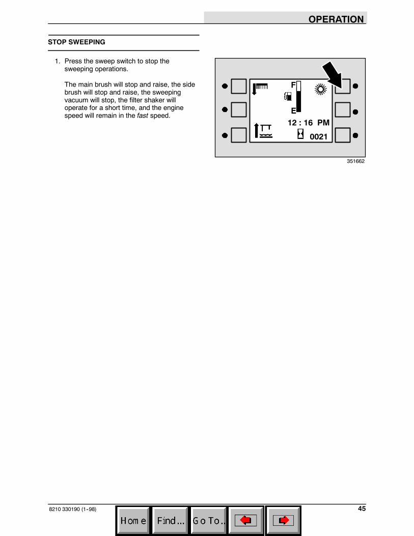
1. Press the sweep switch to stop thesweeping operations.
The main brush will stop and raise, the sidebrush will stop and raise, the sweepingvacuum will stop, the filter shaker willoperate for a short time, and the enginespeed will remain in the fast speed.
F
E12 : 16 PM
0021
351662
OPERATION
8210 330190 (1--98)46
EMPTYING THE HOPPER
1. Stop sweeping.
NOTE: The filter shaker will operate automaticallyand the hopper door will close automatically whensweeping functions are deactivated.
2. Slowly drive the machine to the debris siteor debris container.
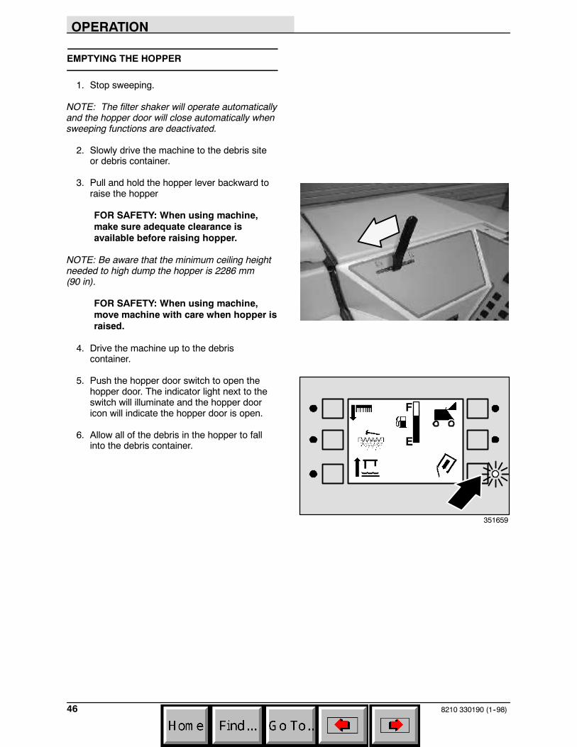
3. Pull and hold the hopper lever backward toraise the hopper
FOR SAFETY: When using machine,make sure adequate clearance isavailable before raising hopper.
NOTE: Be aware that the minimum ceiling heightneeded to high dump the hopper is 2286 mm(90 in).
FOR SAFETY: When using machine,move machine with care when hopper israised.
4. Drive the machine up to the debriscontainer.
5. Push the hopper door switch to open thehopper door. The indicator light next to theswitch will illuminate and the hopper dooricon will indicate the hopper door is open.
6. Allow all of the debris in the hopper to fallinto the debris container.
F
E
351659

OPERATION
478210 330190 (1--98)
7. Push the hopper door switch to close thehopper door. The indicator light next to theswitch will go out and the hopper door iconwill indicate the hopper door is closed.
8. Slowly back the machine away from thedebris site or debris container when all of thedebris has fallen out of the hopper.
FOR SAFETY: When using machine, usecare when reversing machine.
9. Push the hopper lever forward to lower thehopper.
???????
F
E
351663
OPERATION
8210 330190 (12--00)48
FILLING THE TANKS
1. Start the machine.
FOR SAFETY: When starting machine,keep foot on brake and directional pedalin neutral.
2. Drive the machine to the filling site.
3. Shut the engine off.
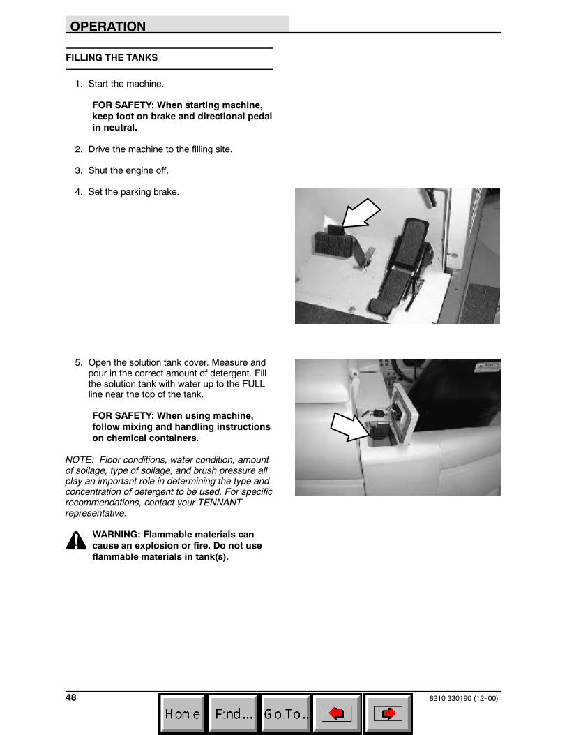
4. Set the parking brake.
5. Open the solution tank cover. Measure andpour in the correct amount of detergent. Fillthe solution tank with water up to the FULLline near the top of the tank.
FOR SAFETY: When using machine,follow mixing and handling instructionson chemical containers.
NOTE: Floor conditions, water condition, amountof soilage, type of soilage, and brush pressure allplay an important role in determining the type andconcentration of detergent to be used. For specificrecommendations, contact your TENNANTrepresentative.
WARNING: Flammable materials cancause an explosion or fire. Do not useflammable materials in tank(s).

OPERATION
498210 330190 (1--98)
6. Remove the detergent tank (option) lid. Fillthe tank to just below the top. Be sure to useonly the proper detergent for your scrubbingapplication. Put the lid back on the detergenttank.
WARNING: Flammable materials cancause an explosion or fire. Do not useflammable materials in tank(s).
NOTE: Floor conditions, water condition, amountof soilage, type of soilage, and brush action allplay an important role in determining the type andconcentration of detergent used. For specificrecommendations, contact your TENNANTrepresentative.
ES mode with auto-fill: Connect the hosefrom the water source to the auto-fillconnection on the machine. Turn the ignitionkey to the on position and turn on the watersource. The auto-fill will automatically fill thetanks to the proper level for ES operationand automatically shut-off.
NOTE: An alarm will sound when the solutiontank is full.
ES mode without auto-fill: Fill the solutiontank to the FULL line.
ES mode without auto-fill: Fill the recoverytank half full of water (to the top of the ESfilter).
NOTE: If you DO NOT want to use the ESsystem, DO NOT put water in the recovery tank.Turn the ES switch OFF.
7. Close the tank cover.
OPERATION
8210 330190 (1--98)50
SCRUBBING
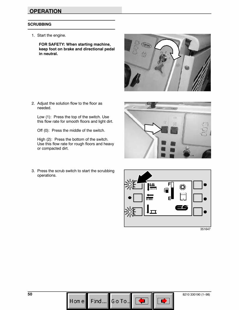
1. Start the engine.
FOR SAFETY: When starting machine,keep foot on brake and directional pedalin neutral.
2. Adjust the solution flow to the floor asneeded.
Low (1): Press the top of the switch. Usethis flow rate for smooth floors and light dirt.
Off (0): Press the middle of the switch.
High (2): Press the bottom of the switch.Use this flow rate for rough floors and heavyor compacted dirt.
3. Press the scrub switch to start the scrubbingoperations.
F
E
351647
OPERATION
518210 330190 (9--99)
As long as the machine is moving forwardthe scrub head will lower and the scrubbrushes will start. The rear squeegee willalso lower and the scrubbing vacuum willstart. The solution flow will start when themachine first begins to move forward, butonly if the solution flow switch is on. Also theoptional ES system and detergent pump willstart, if the switches are on. The enginespeed will change to Fast.
NOTE: The scrub head will raise when thedirectional pedal is in the neutral position. Therear squeegee will raise when the directionalpedal is in the reverse position.
NOTE: If an excess of water in the recovery tankcauses the recovery tank float to rise, an overflowalarm will sound for ten seconds and an overflowicon will appear on the control panel. All scrubbingfunctions will be canceled. To make the overflowicon disappear, drain the recovery tank, thenpress the scrub and squeegee switches.
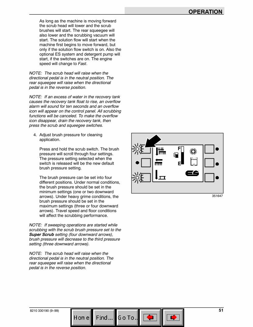
4. Adjust brush pressure for cleaningapplication.
Press and hold the scrub switch. The brushpressure will scroll through four settings.The pressure setting selected when theswitch is released will be the new defaultbrush pressure setting.
The brush pressure can be set into fourdifferent positions. Under normal conditions,the brush pressure should be set in theminimum settings (one or two downwardarrows). Under heavy grime conditions, thebrush pressure should be set in themaximum settings (three or four downwardarrows). Travel speed and floor conditionswill affect the scrubbing performance.
NOTE: If sweeping operations are started whilescrubbing with the scrub brush pressure set to theSuper Scrub setting (four downward arrows),brush pressure will decrease to the third pressuresetting (three downward arrows).
NOTE: The scrub head will raise when thedirectional pedal is in the neutral position. Therear squeegee will raise when the directionalpedal is in the reverse position.
F
E
351647
OPERATION
8210 330190 (12--00)52
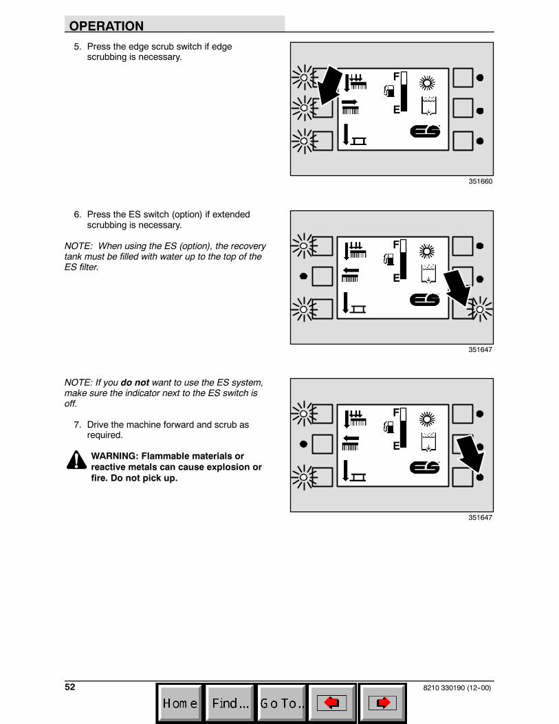
5. Press the edge scrub switch if edgescrubbing is necessary.
6. Press the ES switch (option) if extendedscrubbing is necessary.
NOTE: When using the ES (option), the recoverytank must be filled with water up to the top of theES filter.
NOTE: If you do not want to use the ES system,make sure the indicator next to the ES switch isoff.
7. Drive the machine forward and scrub asrequired.
WARNING: Flammable materials orreactive metals can cause explosion orfire. Do not pick up.
F
E
351660
F
E
351647
F
E
351647
OPERATION
538210 330190 (1--98)
DOUBLE SCRUBBING
Double scrubbing is the process of making two ormore passes over a heavily soiled area. The firstpass is made with the rear squeegee raised toallow the solution to soak into the floor.
Use the maximum solution and detergent flowsettings. Use a higher brush pressure setting. Letthe solution remain on the floor for 5 to 15minutes, then make a second scrubbing passwith the rear squeegee down.
FOR SAFETY: When using machine, goslow on inclines and slippery surfaces.
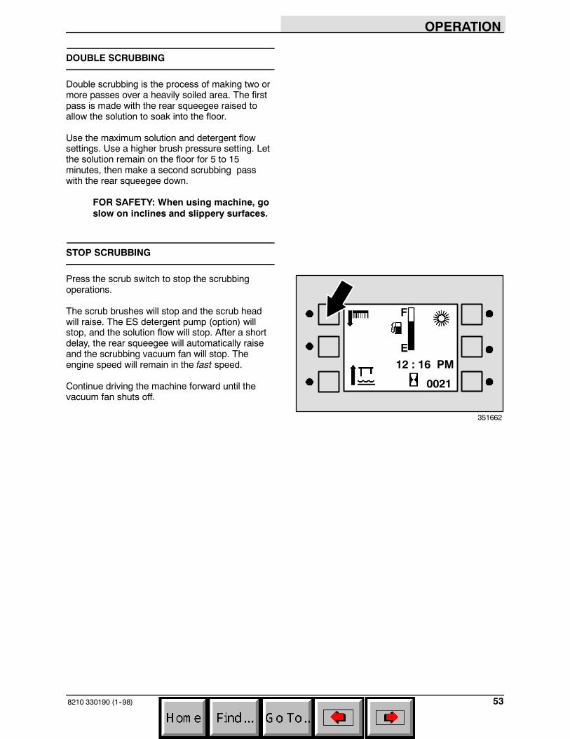
STOP SCRUBBING
Press the scrub switch to stop the scrubbingoperations.
The scrub brushes will stop and the scrub headwill raise. The ES detergent pump (option) willstop, and the solution flow will stop. After a shortdelay, the rear squeegee will automatically raiseand the scrubbing vacuum fan will stop. Theengine speed will remain in the fast speed.
Continue driving the machine forward until thevacuum fan shuts off.
F
E12 : 16 PM
0021
351662
OPERATION
8210 330190 (1--98)54
DRAINING AND CLEANING THE TANKS
When you are finished scrubbing or you hear thevacuum fan shut off and the machine startstrailing water, the recovery tank should be drainedand cleaned. The solution tank then can be filledagain for additional scrubbing.
If you used the machine in ES mode, the solutiontank should also be drained and cleaned whenyou are finished scrubbing.
1. Stop scrubbing.
2. Drive the machine next to an appropriatedisposal site.
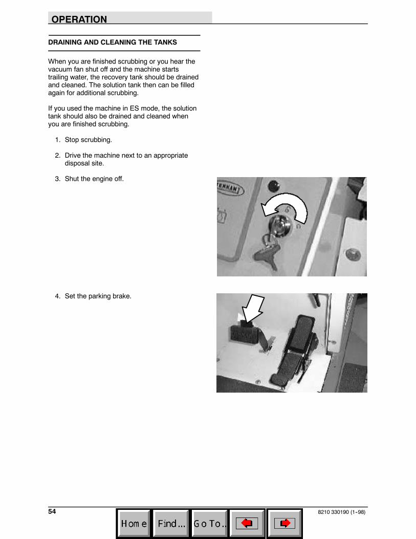
3. Shut the engine off.
4. Set the parking brake.
OPERATION
558210 330190 (1--98)
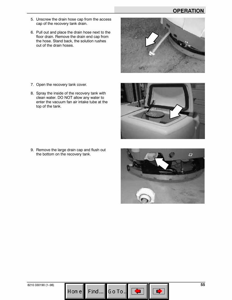
5. Unscrew the drain hose cap from the accesscap of the recovery tank drain.
6. Pull out and place the drain hose next to thefloor drain. Remove the drain end cap fromthe hose. Stand back, the solution rushesout of the drain hoses.
7. Open the recovery tank cover.
8. Spray the inside of the recovery tank withclean water. DO NOT allow any water toenter the vacuum fan air intake tube at thetop of the tank.
9. Remove the large drain cap and flush outthe bottom on the recovery tank.
OPERATION
8210 330190 (1--98)56
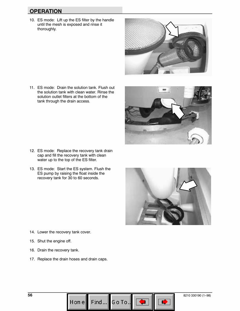
10. ES mode: Lift up the ES filter by the handleuntil the mesh is exposed and rinse itthoroughly.
11. ES mode: Drain the solution tank. Flush outthe solution tank with clean water. Rinse thesolution outlet filters at the bottom of thetank through the drain access.
12. ES mode: Replace the recovery tank draincap and fill the recovery tank with cleanwater up to the top of the ES filter.
13. ES mode: Start the ES system. Flush theES pump by raising the float inside therecovery tank for 30 to 60 seconds.
14. Lower the recovery tank cover.
15. Shut the engine off.
16. Drain the recovery tank.
17. Replace the drain hoses and drain caps.

OPERATION
578210 330190 (6--04)
STOP THE MACHINE
1. Stop sweeping and scrubbing.
2. Take your foot off the directional pedal. Stepon the brake pedal.
3. Shut the engine off. Remove the switch key.
4. Set the machine parking brake.
OPERATION
8210 330190 (1--98)58
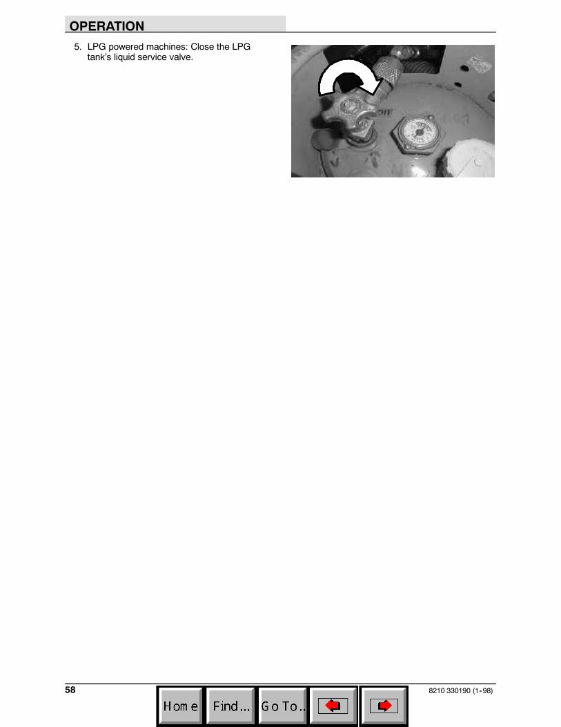
5. LPG powered machines: Close the LPGtank’s liquid service valve.
OPERATION
598210 330190 (6--03)
POST-OPERATION CHECKLIST
- Check the engine oil level.
- Check the engine coolant level.
- Check the radiator and hydraulic cooler finsfor debris.
- Check the hydraulic fluid level
- Check the air filter indicator.
- Check the skirts and seals for damage andwear.
- Check the condition of the sweeping andscrubbing brushes. Remove any string,banding, plastic wrap, or other debriswrapped around them.
- Check the sweeping brush patterns foradjustment.
- Check the condition of the hopper dust filterand seals. Clean as required.
- Check the tank cover seals for damage andwear.
- Clean the vacuum fan inlet filter.
- Check the squeegees for damage, wear andfor deflection adjustment.
- Check the vacuum hose for debris orblockage.
- ES machines; check the detergent tanklevel.
- Drain and clean the recovery tank.
- ES machines; drain and clean the solutiontank and ES filter. Rinse level sensors.
- Check the brakes and steering for properoperation.
- Check the fuel level
- Empty the debris hopper.
- Check the service records to determinemaintenance requirements.
OPERATION
8210 330190 (1--98)60
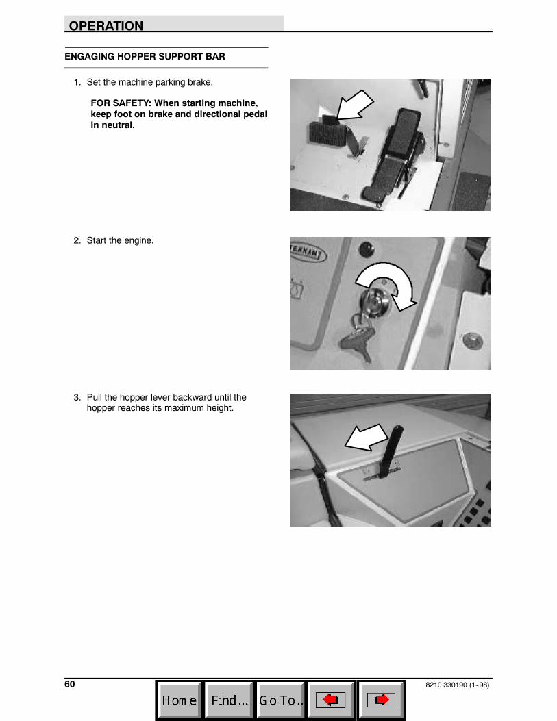
ENGAGING HOPPER SUPPORT BAR
1. Set the machine parking brake.
FOR SAFETY: When starting machine,keep foot on brake and directional pedalin neutral.
2. Start the engine.
3. Pull the hopper lever backward until thehopper reaches its maximum height.
OPERATION
618210 330190 (11--98)
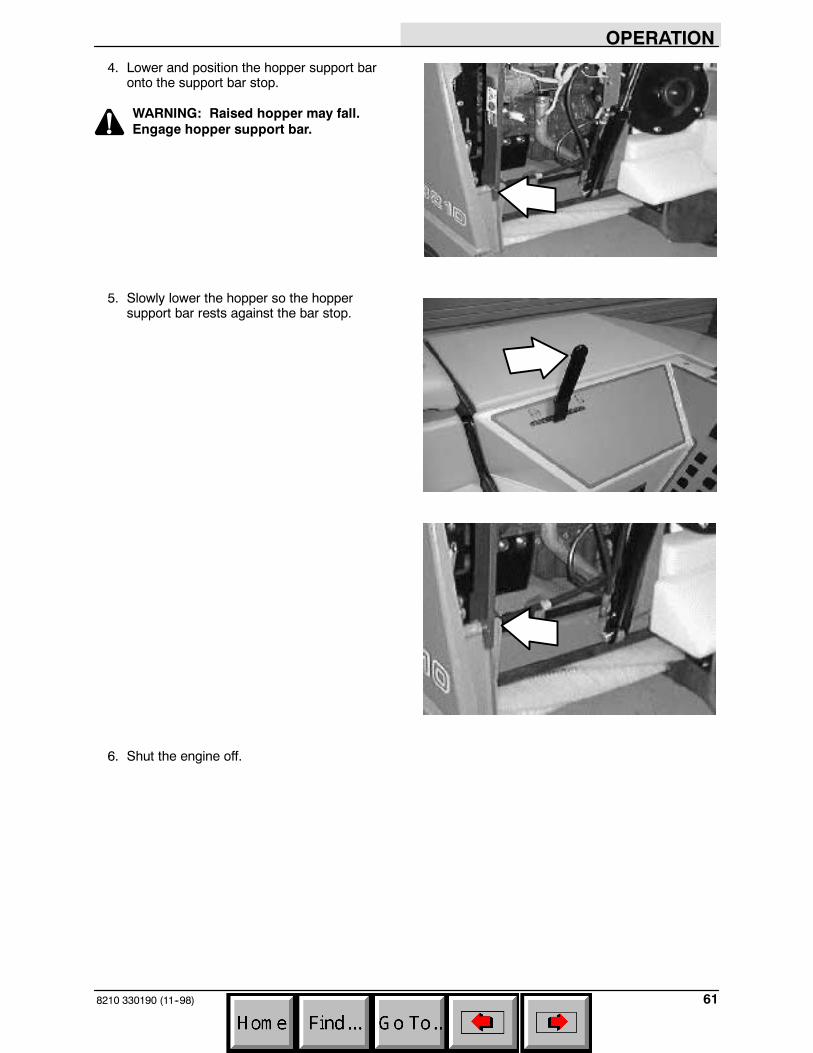
4. Lower and position the hopper support baronto the support bar stop.
WARNING: Raised hopper may fall.Engage hopper support bar.
5. Slowly lower the hopper so the hoppersupport bar rests against the bar stop.
6. Shut the engine off.
OPERATION
8210 330190 (1--98)62
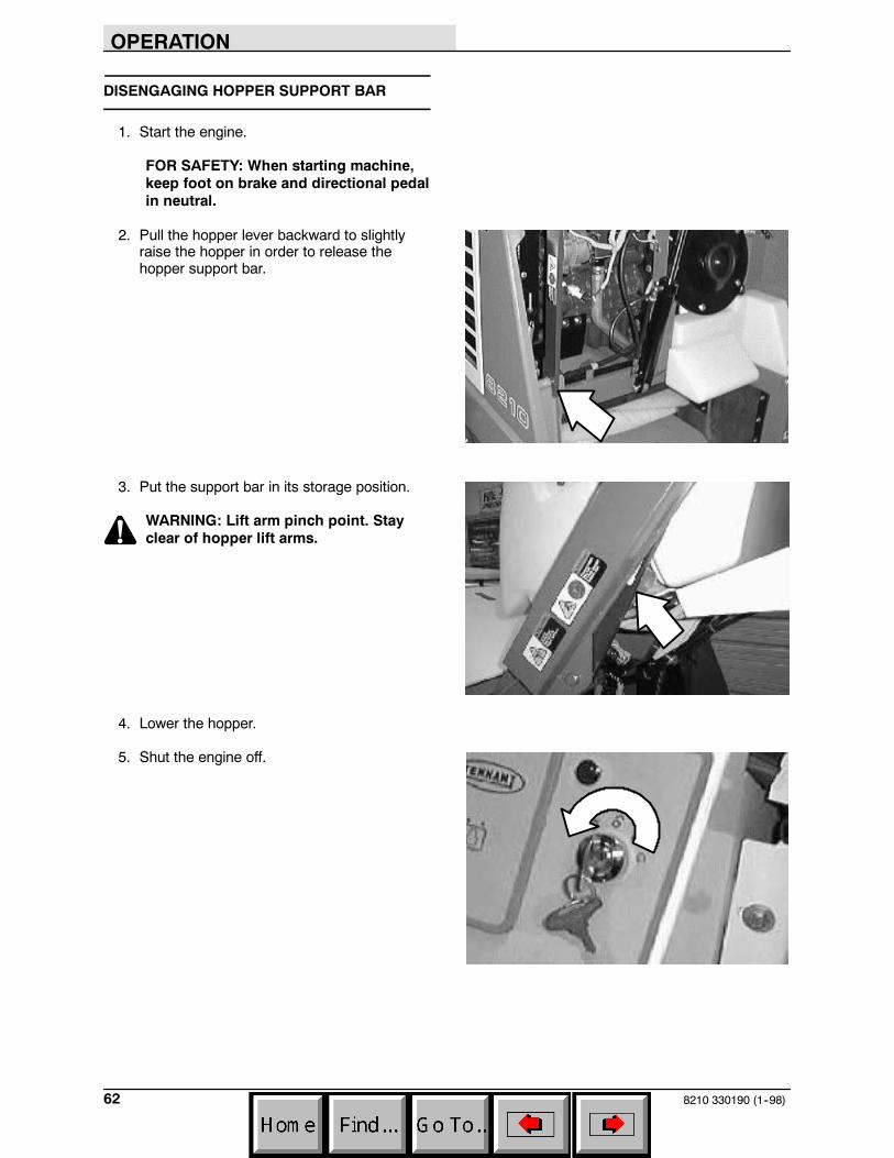
DISENGAGING HOPPER SUPPORT BAR
1. Start the engine.
FOR SAFETY: When starting machine,keep foot on brake and directional pedalin neutral.
2. Pull the hopper lever backward to slightlyraise the hopper in order to release thehopper support bar.
3. Put the support bar in its storage position.
WARNING: Lift arm pinch point. Stayclear of hopper lift arms.
4. Lower the hopper.
5. Shut the engine off.
OPERATION
638210 330190 (1--98)
OPERATION ON INCLINES
Drive the machine slowly on inclines. Use thebrake pedal to control machine speed ondescending inclines. DO NOT turn the machineon an incline; drive straight up or down.
The maximum rated incline for sweeping andscrubbing with the machine is 6_. The maximumrated incline during transport of the machine is 8_.
FOR SAFETY: When using machine, goslow on inclines and slippery surfaces.
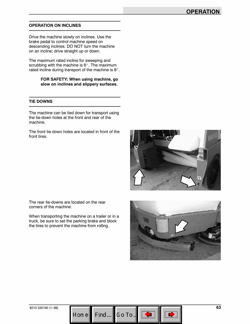
TIE DOWNS
The machine can be tied down for transport usingthe tie-down holes at the front and rear of themachine.
The front tie-down holes are located in front of thefront tires.
The rear tie-downs are located on the rearcorners of the machine.
When transporting the machine on a trailer or in atruck, be sure to set the parking brake and blockthe tires to prevent the machine from rolling.
OPERATION
8210 330190 (1--98)64
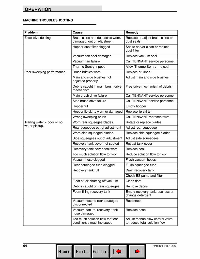
MACHINE TROUBLESHOOTING
Problem Cause Remedy
Excessive dusting Brush skirts and dust seals worn,damaged, out of adjustment
Replace or adjust brush skirts ordust seals
Hopper dust filter clogged Shake and/or clean or replacedust filter
Vacuum fan seal damaged Replace vacuum seal
Vacuum fan failure Call TENNANT service personnel
Thermo Sentry tripped Allow Thermo Sentry to cool
Poor sweeping performance Brush bristles worn Replace brushes
Main and side brushes notadjusted properly
Adjust main and side brushes
Debris caught in main brush drivemechanism
Free drive mechanism of debris
Main brush drive failure Call TENNANT service personnel
Side brush drive failure Call TENNANT service personnel
Hopper full Empty hopper
Hopper lip skirts worn or damaged Replace lip skirts
Wrong sweeping brush Call TENNANT representative
Trailing water -- poor or not i k
Worn rear squeegee blades. Rotate or replace bladeswater pickup. Rear squeegee out of adjustment Adjust rear squeegee
Worn side squeegee blades. Replace side squeegee blades
Side squeegees out of adjustment Adjust side squeegees
Recovery tank cover not seated Reseat tank cover
Recovery tank cover seal worn Replace seal
Too much solution flow to floor Reduce solution flow to floor
Vacuum hose clogged Flush vacuum hoses
Rear squeegee tube clogged Flush squeegee tube
Recovery tank full Drain recovery tank
Check ES pump and filter
Float stuck shutting off vacuum Clean float
Debris caught on rear squeegee Remove debris
Foam filling recovery tank Empty recovery tank; use less orchange detergent
Vacuum hose to rear squeegeedisconnected
Reconnect
Vacuum--fan--to--recovery--tank--hose damaged
Replace hose
Too much solution flow for floorconditions / machine speed
Adjust manual flow control valveto reduce total solution flow
OPERATION
658210 330190 (1--98)
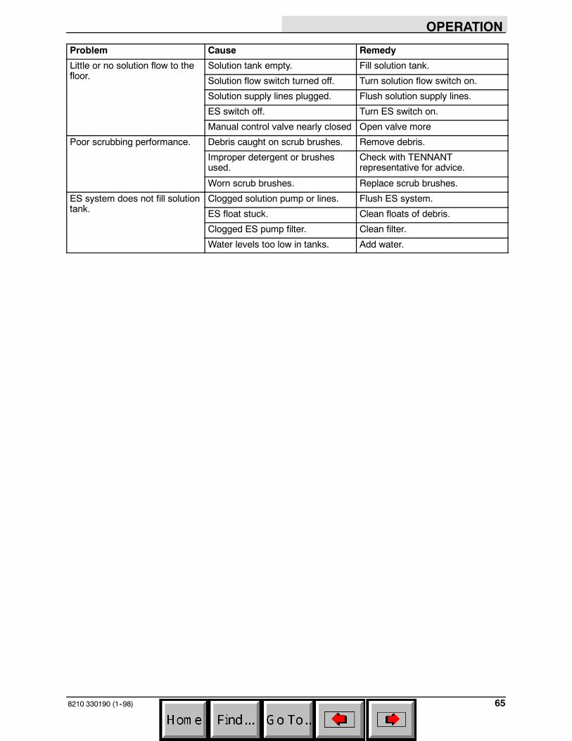
Problem Cause Remedy
Little or no solution flow to thefl
Solution tank empty. Fill solution tank.floor. Solution flow switch turned off. Turn solution flow switch on.
Solution supply lines plugged. Flush solution supply lines.
ES switch off. Turn ES switch on.
Manual control valve nearly closed Open valve more
Poor scrubbing performance. Debris caught on scrub brushes. Remove debris.
Improper detergent or brushesused.
Check with TENNANTrepresentative for advice.
Worn scrub brushes. Replace scrub brushes.
ES system does not fill solutiont k
Clogged solution pump or lines. Flush ES system.tank. ES float stuck. Clean floats of debris.
Clogged ES pump filter. Clean filter.
Water levels too low in tanks. Add water.

MAINTENANCE
8210 330190 (6--04)66
MAINTENANCE
12
3
58
1011
94
7
6
12
13
14
15
16
1718
351551
MAINTENANCE CHART
NOTE: Check procedures indicted (H) after the first 50-hours of operation.
Interval Key Description ProcedureLubricant/
Fluid
No. ofServicePoints
Daily 1 Engine air filter Check indicator -- 1Daily 1 Engine air filterEmpty dust cap -- 1Clean / change filter element asnecessary
-- 1
1 Engine crankcase Check oil level EO 12 Brush compartment skirts Check for damage, wear and
adjustment-- 5
3 Hopper lip skirts Check for damage, wear andadjustment
-- 3
4 Main sweep brush Check for damage, wear, andadjustment
-- 1
Check brush pattern -- 15 Side brush Check for damage, wear, and
adjustment-- 1
Check brush pattern -- 16 Hopper dust filter Shake to clean -- 27 Rear Squeegee Check for damage and wear -- 17 Rear Squeegee
Check deflection -- 18 Side Squeegees Check for damage and wear -- 29 Scrub brushes Check for damage and wear -- 110 Recovery tank Clean -- 110 Recovery tank, ES mode Clean ES filter -- 111 Solution tank, ES mode Clean -- 1
50 Hours 1 Engine crankcase Change oil and filter element EO 14 Main sweep brush Rotate end-for-end -- 1
100 hours 13 Radiator Clean core exterior -- 1100 hours 13 RadiatorCheck coolant level WG 1
1 Engine belts Check belt tension -- 16 Hopper dust filter Check for damage, clean or
replace-- 1
MAINTENANCE
678210 330190 (6--04)
Interval Key Description ProcedureLubricant/
Fluid
No. ofServicePoints
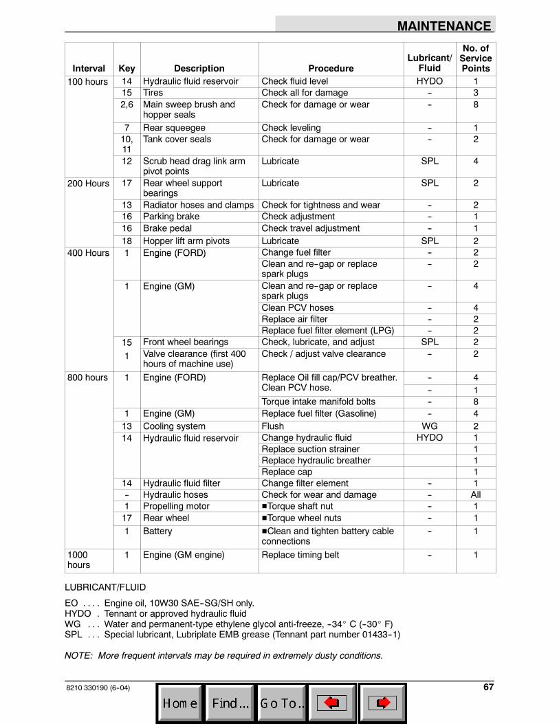
100 hours 14 Hydraulic fluid reservoir Check fluid level HYDO 1100 hours15 Tires Check all for damage -- 32,6 Main sweep brush and
hopper sealsCheck for damage or wear -- 8
7 Rear squeegee Check leveling -- 110,11
Tank cover seals Check for damage or wear -- 2
12 Scrub head drag link armpivot points
Lubricate SPL 4
200 Hours 17 Rear wheel supportbearings
Lubricate SPL 2
13 Radiator hoses and clamps Check for tightness and wear -- 216 Parking brake Check adjustment -- 116 Brake pedal Check travel adjustment -- 118 Hopper lift arm pivots Lubricate SPL 2
400 Hours 1 Engine (FORD) Change fuel filter -- 2400 Hours 1 Engine (FORD)Clean and re--gap or replacespark plugs
-- 2
1 Engine (GM) Clean and re--gap or replacespark plugs
-- 4
Clean PCV hoses -- 4Replace air filter -- 2Replace fuel filter element (LPG) -- 2
15 Front wheel bearings Check, lubricate, and adjust SPL 2151 Valve clearance (first 400
hours of machine use)Check / adjust valve clearance -- 2
800 hours 1 Engine (FORD) Replace Oil fill cap/PCV breather.Cl PCV h
-- 4g ( ) p pClean PCV hose. -- 1Torque intake manifold bolts -- 8
1 Engine (GM) Replace fuel filter (Gasoline) -- 413 Cooling system Flush WG 214 Hydraulic fluid reservoir Change hydraulic fluid HYDO 114 Hydraulic fluid reservoir
Replace suction strainer 1Replace hydraulic breather 1Replace cap 1
14 Hydraulic fluid filter Change filter element -- 1-- Hydraulic hoses Check for wear and damage -- All1 Propelling motor HTorque shaft nut -- 117 Rear wheel HTorque wheel nuts -- 11 Battery HClean and tighten battery cable
connections-- 1
1000hours
1 Engine (GM engine) Replace timing belt -- 1
LUBRICANT/FLUID
EO Engine oil, 10W30 SAE--SG/SH only.. . . .HYDO Tennant or approved hydraulic fluid.WG Water and permanent-type ethylene glycol anti-freeze, --34_ C (--30_ F). . .SPL Special lubricant, Lubriplate EMB grease (Tennant part number 01433--1). . .
NOTE: More frequent intervals may be required in extremely dusty conditions.
MAINTENANCE
8210 330190 (9--99)68
LUBRICATION
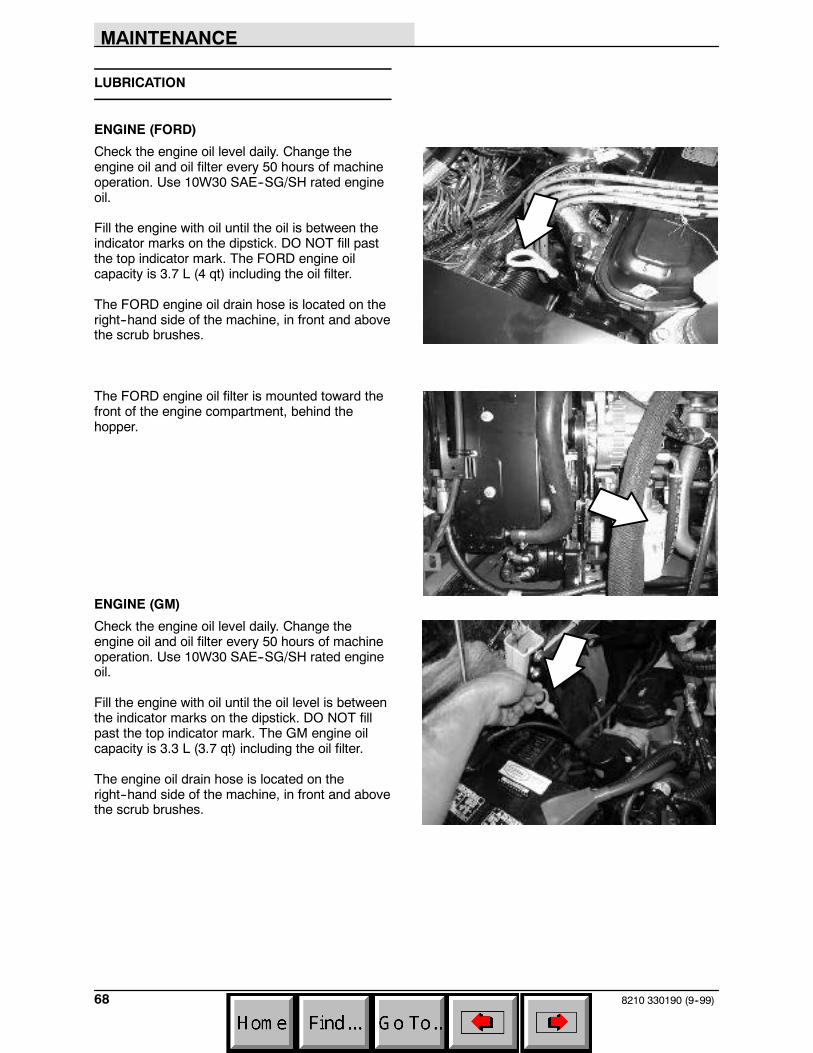
ENGINE (FORD)
Check the engine oil level daily. Change theengine oil and oil filter every 50 hours of machineoperation. Use 10W30 SAE--SG/SH rated engineoil.
Fill the engine with oil until the oil is between theindicator marks on the dipstick. DO NOT fill pastthe top indicator mark. The FORD engine oilcapacity is 3.7 L (4 qt) including the oil filter.
The FORD engine oil drain hose is located on theright--hand side of the machine, in front and abovethe scrub brushes.
The FORD engine oil filter is mounted toward thefront of the engine compartment, behind thehopper.
ENGINE (GM)
Check the engine oil level daily. Change theengine oil and oil filter every 50 hours of machineoperation. Use 10W30 SAE--SG/SH rated engineoil.
Fill the engine with oil until the oil level is betweenthe indicator marks on the dipstick. DO NOT fillpast the top indicator mark. The GM engine oilcapacity is 3.3 L (3.7 qt) including the oil filter.
The engine oil drain hose is located on theright--hand side of the machine, in front and abovethe scrub brushes.
MAINTENANCE
698210 330190 (6--04)
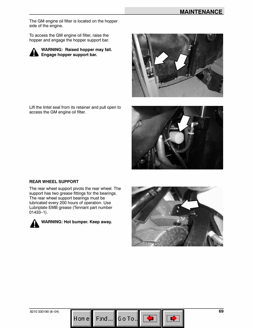
The GM engine oil filter is located on the hopperside of the engine.
To access the GM engine oil filter, raise thehopper and engage the hopper support bar.
WARNING: Raised hopper may fall.Engage hopper support bar.
Lift the lintel seal from its retainer and pull open toaccess the GM engine oil filter.
REAR WHEEL SUPPORT
The rear wheel support pivots the rear wheel. Thesupport has two grease fittings for the bearings.The rear wheel support bearings must belubricated every 200 hours of operation. UseLubriplate EMB grease (Tennant part number01433--1).
WARNING: Hot bumper. Keep away.
MAINTENANCE
8210 330190 (3--06)70
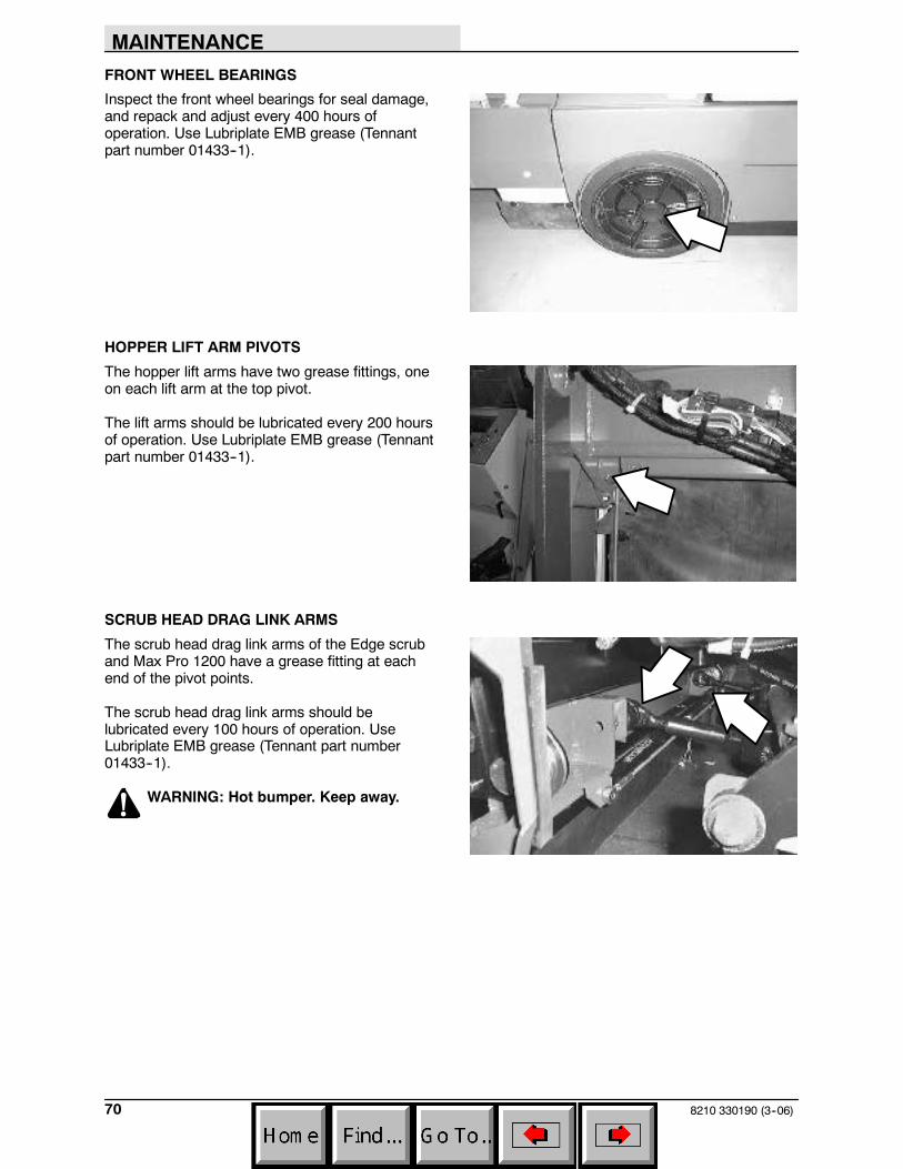
FRONT WHEEL BEARINGS
Inspect the front wheel bearings for seal damage,and repack and adjust every 400 hours ofoperation. Use Lubriplate EMB grease (Tennantpart number 01433--1).
HOPPER LIFT ARM PIVOTS
The hopper lift arms have two grease fittings, oneon each lift arm at the top pivot.
The lift arms should be lubricated every 200 hoursof operation. Use Lubriplate EMB grease (Tennantpart number 01433--1).
SCRUB HEAD DRAG LINK ARMS
The scrub head drag link arms of the Edge scruband Max Pro 1200 have a grease fitting at eachend of the pivot points.
The scrub head drag link arms should belubricated every 100 hours of operation. UseLubriplate EMB grease (Tennant part number01433--1).
WARNING: Hot bumper. Keep away.
MAINTENANCE
718210 330190 (9--05)
HYDRAULICS
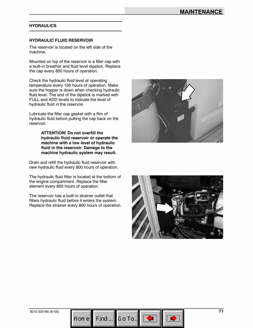
HYDRAULIC FLUID RESERVOIR
The reservoir is located on the left side of themachine.
Mounted on top of the reservoir is a filler cap witha built-in breather and fluid level dipstick. Replacethe cap every 800 hours of operation.
Check the hydraulic fluid level at operatingtemperature every 100 hours of operation. Makesure the hopper is down when checking hydraulicfluid level. The end of the dipstick is marked withFULL and ADD levels to indicate the level ofhydraulic fluid in the reservoir.
Lubricate the filler cap gasket with a film ofhydraulic fluid before putting the cap back on thereservoir.
ATTENTION! Do not overfill thehydraulic fluid reservoir or operate themachine with a low level of hydraulicfluid in the reservoir. Damage to themachine hydraulic system may result.
Drain and refill the hydraulic fluid reservoir withnew hydraulic fluid every 800 hours of operation.
The hydraulic fluid filter is located at the bottom ofthe engine compartment. Replace the filterelement every 800 hours of operation.
The reservoir has a built-in strainer outlet thatfilters hydraulic fluid before it enters the system.Replace the strainer every 800 hours of operation.
MAINTENANCE
8210 330190 (1--98)72
HYDRAULIC FLUID
The quality and condition of the hydraulic fluidplay a very important role in how well the machineoperates. Tennant’s hydraulic fluid is speciallyselected to meet the needs of Tennant machines.
Tennant’s hydraulic fluids provide a longer life forthe hydraulic components. There are two fluidsavailable for different temperature ranges:
Tennant part no. Ambient Temperature
65869 above 7_ C (45_ F)
65870 below 7_ C (45_ F)
The higher temperature fluid has a higherviscosity and should not be used at the lowertemperatures. Damage to the hydraulic pumpsmay occur because of improper lubrication.
The lower temperature fluid is a thinner fluid forcolder temperatures.
If a locally-available hydraulic fluid is used, makesure the specifications match Tennant hydraulicfluid specifications. Using substitute fluids cancause premature failure of hydraulic components.
ATTENTION! Hydraulic componentsdepend on system hydraulic fluid forinternal lubrication. Malfunctions,accelerated wear, and damage will resultif dirt or other contaminants enter thehydraulic system.
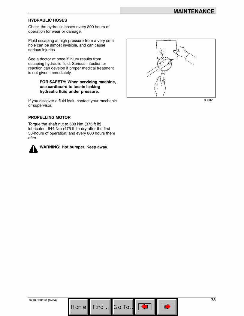
MAINTENANCE
738210 330190 (6--04)
HYDRAULIC HOSES
Check the hydraulic hoses every 800 hours ofoperation for wear or damage.
Fluid escaping at high pressure from a very smallhole can be almost invisible, and can causeserious injuries.
See a doctor at once if injury results fromescaping hydraulic fluid. Serious infection orreaction can develop if proper medical treatmentis not given immediately.
FOR SAFETY: When servicing machine,use cardboard to locate leakinghydraulic fluid under pressure.
If you discover a fluid leak, contact your mechanicor supervisor.
PROPELLING MOTOR
Torque the shaft nut to 508 Nm (375 ft lb)lubricated, 644 Nm (475 ft lb) dry after the first50-hours of operation, and every 800 hours thereafter.
WARNING: Hot bumper. Keep away.
00002
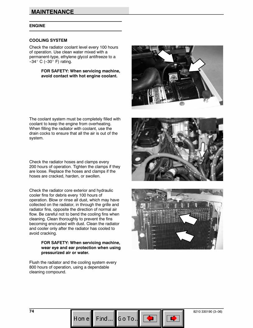
MAINTENANCE
8210 330190 (3--06)74
ENGINE
COOLING SYSTEM
Check the radiator coolant level every 100 hoursof operation. Use clean water mixed with apermanent-type, ethylene glycol antifreeze to a--34_ C (--30_ F) rating.
FOR SAFETY: When servicing machine,avoid contact with hot engine coolant.
The coolant system must be completely filled withcoolant to keep the engine from overheating.When filling the radiator with coolant, use thedrain cocks to ensure that all the air is out of thesystem.
Check the radiator hoses and clamps every200 hours of operation. Tighten the clamps if theyare loose. Replace the hoses and clamps if thehoses are cracked, harden, or swollen.
Check the radiator core exterior and hydrauliccooler fins for debris every 100 hours ofoperation. Blow or rinse all dust, which may havecollected on the radiator, in through the grille andradiator fins, opposite the direction of normal airflow. Be careful not to bend the cooling fins whencleaning. Clean thoroughly to prevent the finsbecoming encrusted with dust. Clean the radiatorand cooler only after the radiator has cooled toavoid cracking.
FOR SAFETY: When servicing machine,wear eye and ear protection when usingpressurized air or water.
Flush the radiator and the cooling system every800 hours of operation, using a dependablecleaning compound.

MAINTENANCE
758210 330190 (6--04)
AIR FILTER INDICATOR (OPTIONAL)
The air filter indicator shows when to replace theair filter element. Check the indicator daily. Theindicator’s red line will move as the air filterelement fills with dirt. Do not replace the air filterelement until the red line reaches5 kPa (20 in H2O) and the “SERVICE WHENRED” window is filled with red. The indicator’s redline may return to a lower reading on the scalewhen the engine shuts off. The red line will returnto a correct reading after the engine runs for awhile.
Reset the air filter indicator by pushing the resetbutton on the end of the indicator after replacingthe air filter element.
AIR FILTER
The engine air filter housing has a dust cap and adry cartridge-type air filter element. Empty thedust cap daily. The air filter must be replacedwhenever the filter element is damaged or whenthe optional air filter indicator shows a restriction.The air filters cannot be cleaned.
Machines with the heavy duty air filter (option)have a safety element inside the the standardelement. Replace the inner element after theregular element becomes damaged or has beenchanged three times.
Install the dust cap on the air filter housing withthe arrows pointing up.
Replace the air filter element only when the airfilter indicator shows restriction in the air intakesystem. Do not remove the air filter element fromthe housing unless it is restricting air flow.
02492
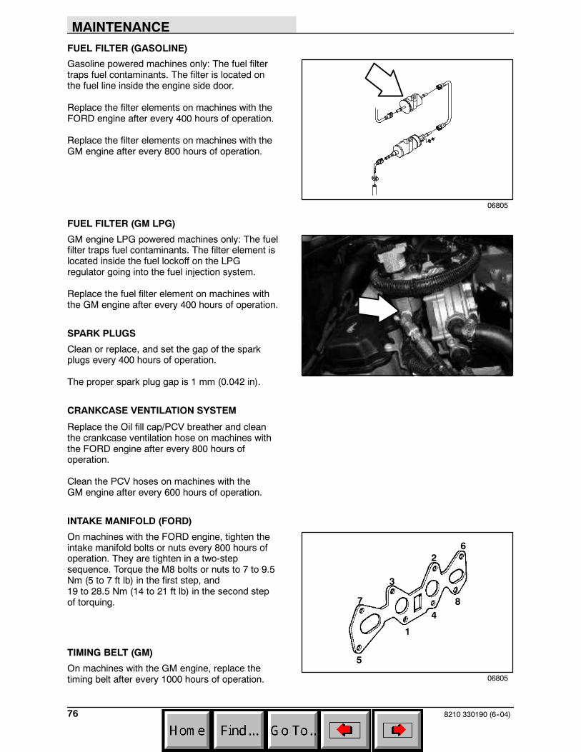
MAINTENANCE
8210 330190 (6--04)76
FUEL FILTER (GASOLINE)
Gasoline powered machines only: The fuel filtertraps fuel contaminants. The filter is located onthe fuel line inside the engine side door.
Replace the filter elements on machines with theFORD engine after every 400 hours of operation.
Replace the filter elements on machines with theGM engine after every 800 hours of operation.
FUEL FILTER (GM LPG)
GM engine LPG powered machines only: The fuelfilter traps fuel contaminants. The filter element islocated inside the fuel lockoff on the LPGregulator going into the fuel injection system.
Replace the fuel filter element on machines withthe GM engine after every 400 hours of operation.
SPARK PLUGS
Clean or replace, and set the gap of the sparkplugs every 400 hours of operation.
The proper spark plug gap is 1 mm (0.042 in).
CRANKCASE VENTILATION SYSTEM
Replace the Oil fill cap/PCV breather and cleanthe crankcase ventilation hose on machines withthe FORD engine after every 800 hours ofoperation.
Clean the PCV hoses on machines with theGM engine after every 600 hours of operation.
INTAKE MANIFOLD (FORD)
On machines with the FORD engine, tighten theintake manifold bolts or nuts every 800 hours ofoperation. They are tighten in a two-stepsequence. Torque the M8 bolts or nuts to 7 to 9.5Nm (5 to 7 ft lb) in the first step, and19 to 28.5 Nm (14 to 21 ft lb) in the second stepof torquing.
TIMING BELT (GM)
On machines with the GM engine, replace thetiming belt after every 1000 hours of operation.
06805
06805
1
2
3
4
5
6
7 8
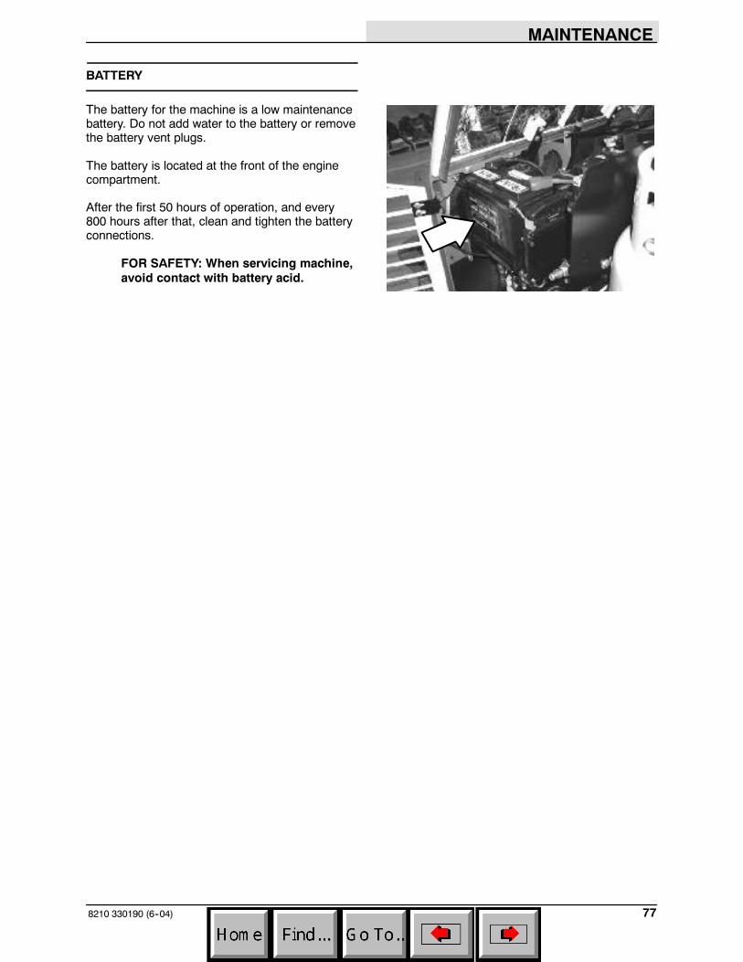
MAINTENANCE
778210 330190 (6--04)
BATTERY
The battery for the machine is a low maintenancebattery. Do not add water to the battery or removethe battery vent plugs.
The battery is located at the front of the enginecompartment.
After the first 50 hours of operation, and every800 hours after that, clean and tighten the batteryconnections.
FOR SAFETY: When servicing machine,avoid contact with battery acid.
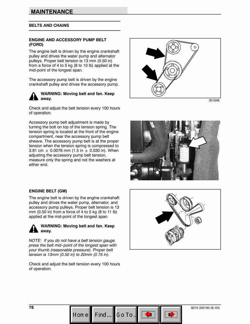
MAINTENANCE
8210 330190 (6--04)78
BELTS AND CHAINS
ENGINE AND ACCESSORY PUMP BELT(FORD)
The engine belt is driven by the engine crankshaftpulley and drives the water pump and alternatorpulleys. Proper belt tension is 13 mm (0.50 in)from a force of 4 to 5 kg (8 to 10 lb) applied at themid-point of the longest span.
The accessory pump belt is driven by the enginecrankshaft pulley and drives the accessory pump.
WARNING: Moving belt and fan. Keepaway.
Check and adjust the belt tension every 100 hoursof operation.
Accessory pump belt adjustment is made byturning the bolt on top of the tension spring. Thetension spring is located at the front of the enginecompartment, near the accessory pump beltsheave. The accessory pump belt is at the propertension when the tension spring is compressed to3.81 cm 0.0076 mm (1.5 in 0.030 in). Whenadjusting the accessory pump belt tension,measure only the spring and not the washers ateither end.
ENGINE BELT (GM)
The engine belt is driven by the engine crankshaftpulley and drives the water pump, alternator, andaccessory pump pulleys. Proper belt tension is 13mm (0.50 in) from a force of 4 to 5 kg (8 to 11 lb)applied at the mid-point of the longest span.
WARNING: Moving belt and fan. Keepaway.
NOTE: If you do not have a belt tension gauge,press the belt mid--point of the longest span withyour thumb (reasonable pressure). Proper belttension is 13mm (0.50 in) to 20mm (0.75 in).
Check and adjust the belt tension every 100 hoursof operation.
351646
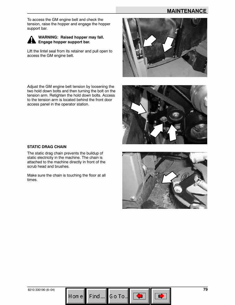
MAINTENANCE
798210 330190 (6--04)
To access the GM engine belt and check thetension, raise the hopper and engage the hoppersupport bar.
WARNING: Raised hopper may fall.Engage hopper support bar.
Lift the lintel seal from its retainer and pull open toaccess the GM engine belt.
Adjust the GM engine belt tension by loosening thetwo hold down bolts and then turning the bolt on thetension arm. Retighten the hold down bolts. Accessto the tension arm is located behind the front dooraccess panel in the operator station.
STATIC DRAG CHAIN
The static drag chain prevents the buildup ofstatic electricity in the machine. The chain isattached to the machine directly in front of thescrub head and brushes.
Make sure the chain is touching the floor at alltimes.
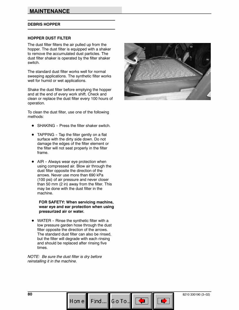
MAINTENANCE
8210 330190 (3--02)80
DEBRIS HOPPER
HOPPER DUST FILTER
The dust filter filters the air pulled up from thehopper. The dust filter is equipped with a shakerto remove the accumulated dust particles. Thedust filter shaker is operated by the filter shakerswitch.
The standard dust filter works well for normalsweeping applications. The synthetic filter workswell for humid or wet applications.
Shake the dust filter before emptying the hopperand at the end of every work shift. Check andclean or replace the dust filter every 100 hours ofoperation.
To clean the dust filter, use one of the followingmethods:
D SHAKING -- Press the filter shaker switch.
D TAPPING -- Tap the filter gently on a flatsurface with the dirty side down. Do notdamage the edges of the filter element orthe filter will not seat properly in the filterframe.
D AIR -- Always wear eye protection whenusing compressed air. Blow air through thedust filter opposite the direction of thearrows. Never use more than 690 kPa(100 psi) of air pressure and never closerthan 50 mm (2 in) away from the filter. Thismay be done with the dust filter in themachine.
FOR SAFETY: When servicing machine,wear eye and ear protection when usingpressurized air or water.
D WATER -- Rinse the synthetic filter with alow pressure garden hose through the dustfilter opposite the direction of the arrows.The standard dust filter can also be rinsed,but the filter will degrade with each rinsingand should be replaced after rinsing fivetimes.
NOTE: Be sure the dust filter is dry beforereinstalling it in the machine.
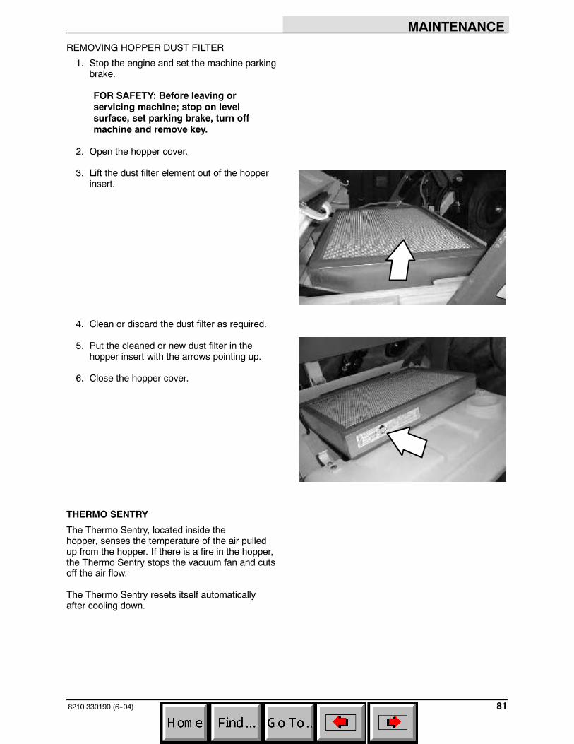
MAINTENANCE
818210 330190 (6--04)
REMOVING HOPPER DUST FILTER
1. Stop the engine and set the machine parkingbrake.
FOR SAFETY: Before leaving orservicing machine; stop on levelsurface, set parking brake, turn offmachine and remove key.
2. Open the hopper cover.
3. Lift the dust filter element out of the hopperinsert.
4. Clean or discard the dust filter as required.
5. Put the cleaned or new dust filter in thehopper insert with the arrows pointing up.
6. Close the hopper cover.
THERMO SENTRY
The Thermo Sentry, located inside thehopper, senses the temperature of the air pulledup from the hopper. If there is a fire in the hopper,the Thermo Sentry stops the vacuum fan and cutsoff the air flow.
The Thermo Sentry resets itself automaticallyafter cooling down.
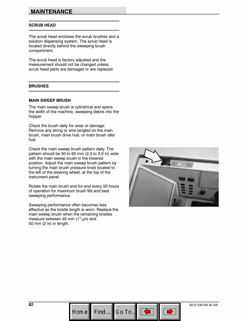
MAINTENANCE
8210 330190 (6--03)82
SCRUB HEAD
The scrub head encloses the scrub brushes and asolution dispensing system. The scrub head islocated directly behind the sweeping brushcompartment.
The scrub head is factory adjusted and themeasurement should not be changed unlessscrub head parts are damaged or are replaced.
BRUSHES
MAIN SWEEP BRUSH
The main sweep brush is cylindrical and spansthe width of the machine, sweeping debris into thehopper.
Check the brush daily for wear or damage.Remove any string or wire tangled on the mainbrush, main brush drive hub, or main brush idlerhub.
Check the main sweep brush pattern daily. Thepattern should be 50 to 65 mm (2.0 to 3.0 in) widewith the main sweep brush in the loweredposition. Adjust the main sweep brush pattern byturning the main brush pressure knob located tothe left of the steering wheel, at the top of theinstrument panel.
Rotate the main brush end-for-end every 50 hoursof operation for maximum brush life and bestsweeping performance.
Sweeping performance often becomes lesseffective as the bristle length is worn. Replace themain sweep brush when the remaining bristlesmeasure between 40 mm (11/2in) and50 mm (2 in) in length.
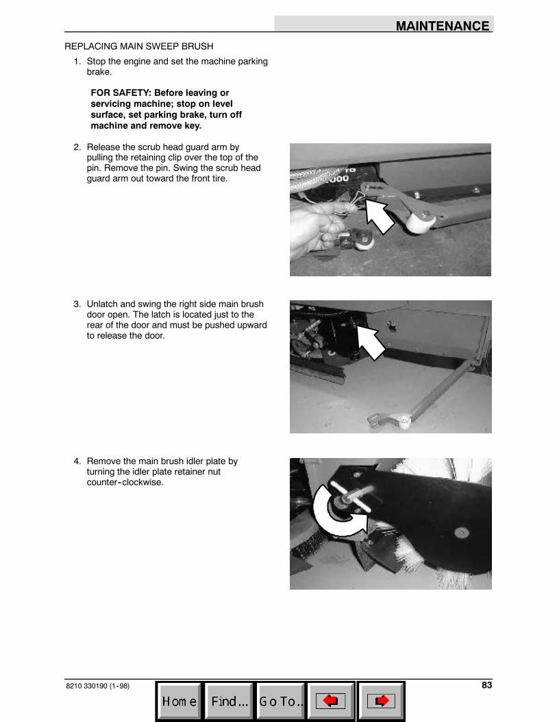
MAINTENANCE
838210 330190 (1--98)
REPLACING MAIN SWEEP BRUSH
1. Stop the engine and set the machine parkingbrake.
FOR SAFETY: Before leaving orservicing machine; stop on levelsurface, set parking brake, turn offmachine and remove key.
2. Release the scrub head guard arm bypulling the retaining clip over the top of thepin. Remove the pin. Swing the scrub headguard arm out toward the front tire.
3. Unlatch and swing the right side main brushdoor open. The latch is located just to therear of the door and must be pushed upwardto release the door.
4. Remove the main brush idler plate byturning the idler plate retainer nutcounter--clockwise.

MAINTENANCE
8210 330190 (1--98)84
5. Pull the main sweep brush off the brushdrive plug and out of the main brushcompartment.
6. Rotate the main brush end for end or, ifnecessary, install a new main brush.
7. Slide the main sweep brush onto the driveplug. Rotate the brush until it engages thedrive plug. Push it all the way onto the plug.
8. Replace the main brush idler plate andsecure it by turning the idler plate retainernut clockwise.
9. Close and latch the main brush door, thenswing the scrub head guard arm back inplace and replace the pin. Install the pinfrom the bottom up.

MAINTENANCE
858210 330190 (1--98)
CHECKING AND ADJUSTING MAIN SWEEPBRUSH PATTERN
1. Apply chalk, or some other material that willnot easily blow away to a smooth and levelsection of the floor.
NOTE: If chalk or other material is not available,in Step 4 allow the sweep brush to spin on thefloor for two minutes. A polish mark will remain onthe floor.
2. Position the main sweep brush over thechalked area.
3. Start the main sweep brush.
4. Allow the main brush to sweep for 15 to 20seconds while keeping a foot on the brakesto keep the machine from moving.
NOTE: If chalk or other material is not available,allow the sweep brush to spin on the floor for twominutes. A polish mark will remain on the floor.
5. Stop the main sweep brush.
6. Drive the machine off the test area.
7. Observe the width of the brush pattern. Theproper brush pattern width is 50 to 65 mm(2.0 to 3.0 in).
00582
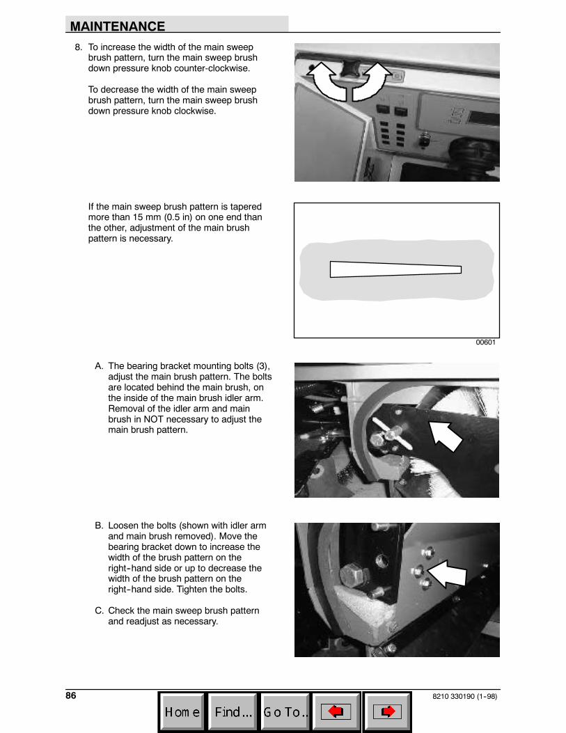
MAINTENANCE
8210 330190 (1--98)86
8. To increase the width of the main sweepbrush pattern, turn the main sweep brushdown pressure knob counter-clockwise.
To decrease the width of the main sweepbrush pattern, turn the main sweep brushdown pressure knob clockwise.
If the main sweep brush pattern is taperedmore than 15 mm (0.5 in) on one end thanthe other, adjustment of the main brushpattern is necessary.
A. The bearing bracket mounting bolts (3),adjust the main brush pattern. The boltsare located behind the main brush, onthe inside of the main brush idler arm.Removal of the idler arm and mainbrush in NOT necessary to adjust themain brush pattern.
B. Loosen the bolts (shown with idler armand main brush removed). Move thebearing bracket down to increase thewidth of the brush pattern on theright--hand side or up to decrease thewidth of the brush pattern on theright--hand side. Tighten the bolts.
C. Check the main sweep brush patternand readjust as necessary.
00601
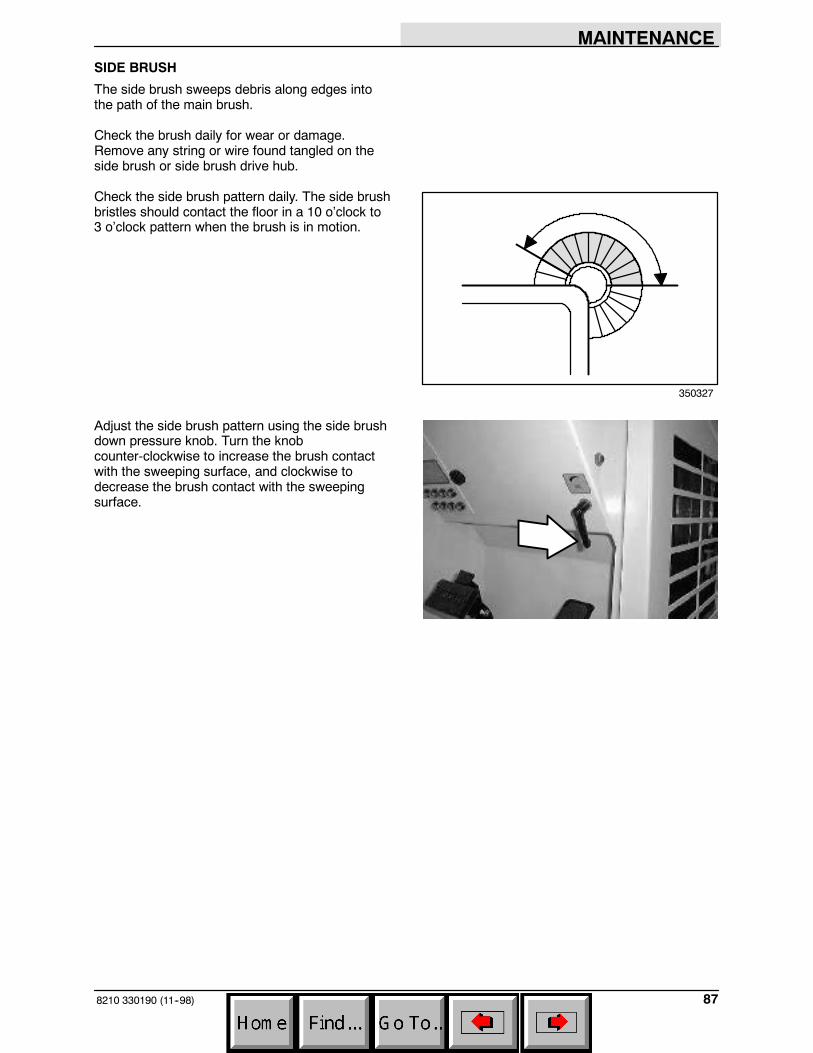
MAINTENANCE
878210 330190 (11--98)
SIDE BRUSH
The side brush sweeps debris along edges intothe path of the main brush.
Check the brush daily for wear or damage.Remove any string or wire found tangled on theside brush or side brush drive hub.
Check the side brush pattern daily. The side brushbristles should contact the floor in a 10 o’clock to3 o’clock pattern when the brush is in motion.
Adjust the side brush pattern using the side brushdown pressure knob. Turn the knobcounter-clockwise to increase the brush contactwith the sweeping surface, and clockwise todecrease the brush contact with the sweepingsurface.
350327
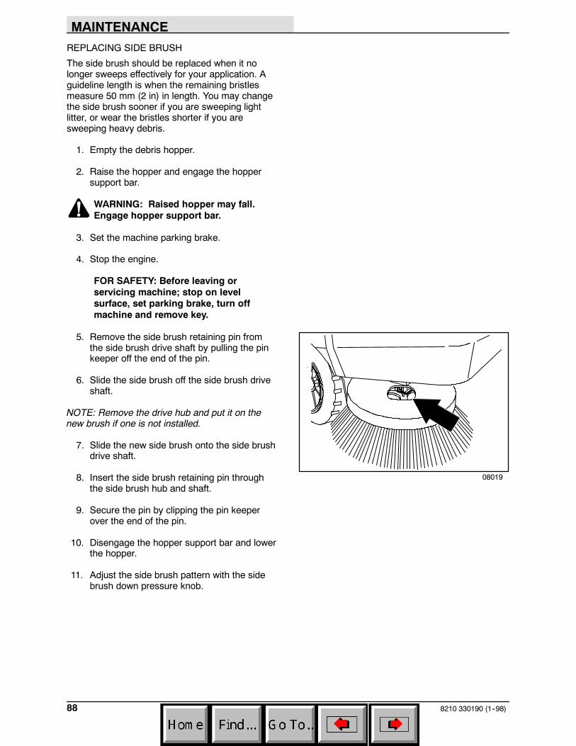
MAINTENANCE
8210 330190 (1--98)88
REPLACING SIDE BRUSH
The side brush should be replaced when it nolonger sweeps effectively for your application. Aguideline length is when the remaining bristlesmeasure 50 mm (2 in) in length. You may changethe side brush sooner if you are sweeping lightlitter, or wear the bristles shorter if you aresweeping heavy debris.
1. Empty the debris hopper.
2. Raise the hopper and engage the hoppersupport bar.
WARNING: Raised hopper may fall.Engage hopper support bar.
3. Set the machine parking brake.
4. Stop the engine.
FOR SAFETY: Before leaving orservicing machine; stop on levelsurface, set parking brake, turn offmachine and remove key.
5. Remove the side brush retaining pin fromthe side brush drive shaft by pulling the pinkeeper off the end of the pin.
6. Slide the side brush off the side brush driveshaft.
NOTE: Remove the drive hub and put it on thenew brush if one is not installed.
7. Slide the new side brush onto the side brushdrive shaft.
8. Insert the side brush retaining pin throughthe side brush hub and shaft.
9. Secure the pin by clipping the pin keeperover the end of the pin.
10. Disengage the hopper support bar and lowerthe hopper.
11. Adjust the side brush pattern with the sidebrush down pressure knob.
08019

MAINTENANCE
898210 330190 (1--98)
SCRUB BRUSHES
Two disc-type scrub brushes scrub the floor.Optional three brush scrub heads are available. Aspring lock clip holds the scrub brushes onto thedrive hubs.
The scrub brushes should be checked daily fortangled wire or string, wear, and damage. Thebrushes should be replaced if large portions of thebrush bristles are missing or if the remainingbrush bristle measure 0.50 in (12 mm) or less inlength.
NOTE: Replace all scrub brushes at the sametime to ensure equal scrubbing performance.
To use the stripping, scrubbing, buffing, orpolishing pads, install the pads onto brush drivers.Secure each pad onto the driver with a padretaining plug. Install the brush drivers in place ofthe normal scrubbing brushes. Use the normalamount of detergent and water.
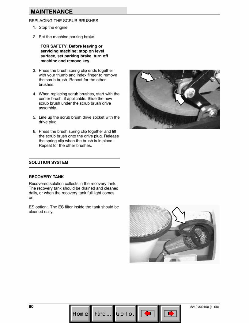
MAINTENANCE
8210 330190 (1--98)90
REPLACING THE SCRUB BRUSHES
1. Stop the engine.
2. Set the machine parking brake.
FOR SAFETY: Before leaving orservicing machine; stop on levelsurface, set parking brake, turn offmachine and remove key.
3. Press the brush spring clip ends togetherwith your thumb and index finger to removethe scrub brush. Repeat for the otherbrushes.
4. When replacing scrub brushes, start with thecenter brush, if applicable. Slide the newscrub brush under the scrub brush driveassembly.
5. Line up the scrub brush drive socket with thedrive plug.
6. Press the brush spring clip together and liftthe scrub brush onto the drive plug. Releasethe spring clip when the brush is in place.Repeat for the other brushes.
SOLUTION SYSTEM
RECOVERY TANK
Recovered solution collects in the recovery tank.The recovery tank should be drained and cleaneddaily, or when the recovery tank full light comeson.
ES option: The ES filter inside the tank should becleaned daily.

MAINTENANCE
918210 330190 (12--00)
The vacuum fan air intake screen should bechecked daily and cleaned as necessary. To cleanthe screen, remove it and spray it off with a hose.DO NOT allow any water to enter the vacuum fanair intake tube.
SOLUTION TANK
The solution tank contains the cleaning solution.
The solution tank does not require regularmaintenance. If deposits form on the bottom ofthe tank, rinse the tank with a strong blast ofwarm water. The tank can be flushed through thedrain opening. Drain the tank with the solutiontank drain hose.
The solution tank on machines with the ES optionshould be drained and cleaned daily. Rinse thesolution outlet filters at the bottom of the tankthrough the drain access.
SQUEEGEES
The rear squeegee channels water into thevacuum fan suction. The front blade channels thewater, and the rear blade wipes the floor.
The side squeegees control water spray andchannel water into the path of the rear squeegee.
REAR SQUEEGEE
Check the squeegee blades for damage and weardaily. Rotate or replace either of the squeegeeblades if the leading edge is torn or worn half-waythrough the thickness of the blade.
The squeegee can be adjusted for leveling anddeflection. The deflection of the squeegee bladesshould be checked daily, or when scrubbing adifferent type of floor. The leveling of thesqueegee should be checked every 100 hours ofmachine operation.
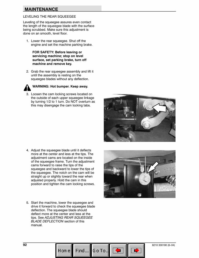
MAINTENANCE
8210 330190 (6--04)92
LEVELING THE REAR SQUEEGEE
Leveling of the squeegee assures even contactthe length of the squeegee blade with the surfacebeing scrubbed. Make sure this adjustment isdone on an smooth, level floor.
1. Lower the rear squeegee. Shut off theengine and set the machine parking brake.
FOR SAFETY: Before leaving orservicing machine; stop on levelsurface, set parking brake, turn offmachine and remove key.
2. Grab the rear squeegee assembly and lift ituntil the assembly is resting on thesqueegee blades without any deflection.
WARNING: Hot bumper. Keep away.
3. Loosen the cam locking screws located onthe outside of each upper squeegee linkageby turning 1/2 to 1 turn. Do NOT overturn asthis may disengage the cam locking tabs.
4. Adjust the squeegee blade until it deflectsmore at the center and less at the tips. Theadjustment cams are located on the insideof the squeegee frame. Turn the adjustmentcams forward to raise the tips of thesqueegee and backward to lower the tips ofthe squeegee. The notch on the cam will bestraight up or slightly toward the rear whenadjusted properly. Hold the cam in thisposition and tighten the cam locking screws.
5. Start the machine, lower the squeegee anddrive it forward to check the squeegee bladedeflection. The squeegee blade shoulddeflect more at the center and less at thetips. See ADJUSTING REAR SQUEEGEEBLADE DEFLECTION section of thismanual.
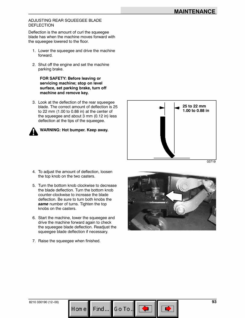
MAINTENANCE
938210 330190 (12--00)
ADJUSTING REAR SQUEEGEE BLADEDEFLECTION
Deflection is the amount of curl the squeegeeblade has when the machine moves forward withthe squeegee lowered to the floor.
1. Lower the squeegee and drive the machineforward.
2. Shut off the engine and set the machineparking brake.
FOR SAFETY: Before leaving orservicing machine; stop on levelsurface, set parking brake, turn offmachine and remove key.
3. Look at the deflection of the rear squeegeeblade. The correct amount of deflection is 25to 22 mm (1.00 to 0.88 in) at the center ofthe squeegee and about 3 mm (0.12 in) lessdeflection at the tips of the squeegee.
WARNING: Hot bumper. Keep away.
4. To adjust the amount of deflection, loosenthe top knob on the two casters.
5. Turn the bottom knob clockwise to decreasethe blade deflection. Turn the bottom knobcounter-clockwise to increase the bladedeflection. Be sure to turn both knobs thesame number of turns. Tighten the topknobs on the casters.
6. Start the machine, lower the squeegee anddrive the machine forward again to checkthe squeegee blade deflection. Readjust thesqueegee blade deflection if necessary.
7. Raise the squeegee when finished.
03719
25 to 22 mm1.00 to 0.88 in

MAINTENANCE
8210 330190 (12--00)94
SIDE SQUEEGEES
ADJUSTING THE SIDE SQUEEGEES
The side squeegee has one adjustment; height.To change the height adjustment, disconnect thesqueegee spring from the clevis pin and move theclevis pin to a different hole location.
WARNING: Hot bumper. Keep away.
SQUEEGEE BLADES
REAR SQUEEGEE
The rear squeegee has two squeegee blades.Each blade has four wiping edges. To use themall, start with one wiping edge. To use the nextwiping edge, rotate the blade end-for-end. To usethe next wiping edge, rotate the top edges down,bottom edges up. To use the last edge, rotate theblade end-for-end.
Replace any worn or damaged squeegee blades.
REPLACING OR ROTATING REAR SQUEEGEEBLADES
1. Make sure the squeegee is raised off thefloor.
2. Shut the engine off and set the parkingbrake.
FOR SAFETY: Before leaving orservicing machine; stop on levelsurface, set parking brake, turn offmachine and remove key.
3. Open the retaining band clamp and removethe squeegee blade.
4. Replace or rotate the squeegee blade toallow a new edge to face the front of themachine.
5. Place the squeegee blade over theprotrusions of the squeegee frame.
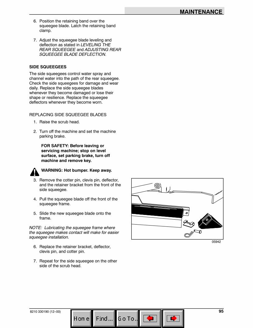
MAINTENANCE
958210 330190 (12--00)
6. Position the retaining band over thesqueegee blade. Latch the retaining bandclamp.
7. Adjust the squeegee blade leveling anddeflection as stated in LEVELING THEREAR SQUEEGEE and ADJUSTING REARSQUEEGEE BLADE DEFLECTION.
SIDE SQUEEGEES
The side squeegees control water spray andchannel water into the path of the rear squeegee.Check the side squeegees for damage and weardaily. Replace the side squeegee bladeswhenever they become damaged or lose theirshape or resilience. Replace the squeegeedeflectors whenever they become worn.
REPLACING SIDE SQUEEGEE BLADES
1. Raise the scrub head.
2. Turn off the machine and set the machineparking brake.
FOR SAFETY: Before leaving orservicing machine; stop on levelsurface, set parking brake, turn offmachine and remove key.
WARNING: Hot bumper. Keep away.
3. Remove the cotter pin, clevis pin, deflector,and the retainer bracket from the front of theside squeegee.
4. Pull the squeegee blade off the front of thesqueegee frame.
5. Slide the new squeegee blade onto theframe.
NOTE: Lubricating the squeegee frame wherethe squeegee makes contact will make for easiersqueegee installation.
6. Replace the retainer bracket, deflector,clevis pin, and cotter pin.
7. Repeat for the side squeegee on the otherside of the scrub head.
05942
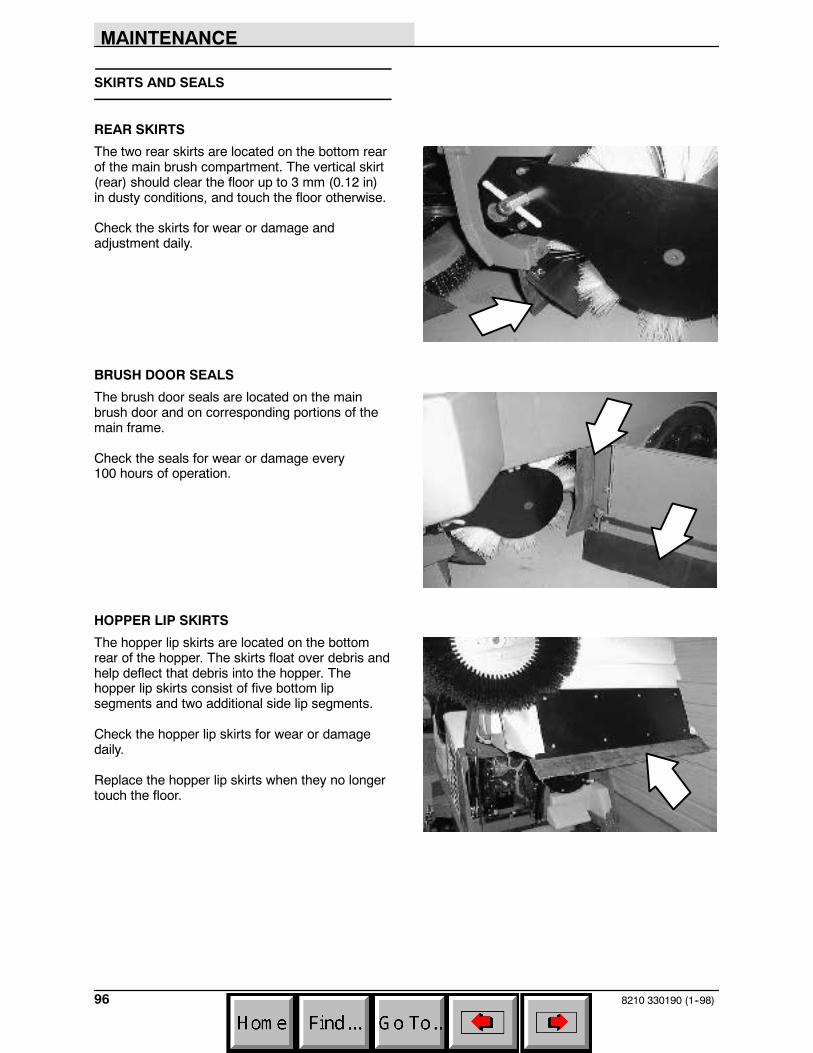
MAINTENANCE
8210 330190 (1--98)96
SKIRTS AND SEALS
REAR SKIRTS
The two rear skirts are located on the bottom rearof the main brush compartment. The vertical skirt(rear) should clear the floor up to 3 mm (0.12 in)in dusty conditions, and touch the floor otherwise.
Check the skirts for wear or damage andadjustment daily.
BRUSH DOOR SEALS
The brush door seals are located on the mainbrush door and on corresponding portions of themain frame.
Check the seals for wear or damage every100 hours of operation.
HOPPER LIP SKIRTS
The hopper lip skirts are located on the bottomrear of the hopper. The skirts float over debris andhelp deflect that debris into the hopper. Thehopper lip skirts consist of five bottom lipsegments and two additional side lip segments.
Check the hopper lip skirts for wear or damagedaily.
Replace the hopper lip skirts when they no longertouch the floor.

MAINTENANCE
978210 330190 (1--98)
HOPPER SEALS
The hopper seals are located on the top and sideportions of the machine frame that contact thehopper.
Check the seals for wear or damage every100 hours of operation.
WARNING: Raised hopper may fall.Engage hopper support bar.
HOPPER DOOR SEALS
There are hopper door seals located on threesides of the hopper door. They seal the hopperwhen the hopper door is closed.
Check the seals for wear or damage every100 hours of operation.
HOPPER FILTER SEALS
The filter seals are located on both sides of thedust filter. They seal the hopper filter to the coverand hopper.
Check the seal for wear or damage every100 hours of operation.
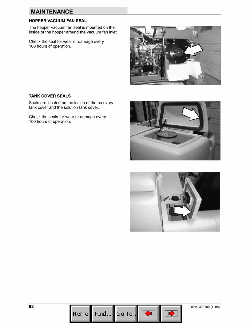
MAINTENANCE
8210 330190 (1--98)98
HOPPER VACUUM FAN SEAL
The hopper vacuum fan seal is mounted on theinside of the hopper around the vacuum fan inlet.
Check the seal for wear or damage every100 hours of operation.
TANK COVER SEALS
Seals are located on the inside of the recoverytank cover and the solution tank cover.
Check the seals for wear or damage every100 hours of operation.

MAINTENANCE
998210 330190 (3--02)
BRAKES AND TIRES
SERVICE BRAKES
The mechanical service brakes are located on thefront wheels. The brakes are operated by the footbrake pedal and connecting cables.
Check the brake adjustment every 200 hours ofoperation.
PARKING BRAKE
The parking brake is set with a parking brakepedal that locks the brake pedal.
TIRES
The machine tires are solid. Check the tires every100 hours of operation for damage and wear.
REAR WHEEL
Torque the rear wheel nuts twice in the patternshown to 142 to 156 Nm (105 to 115 ft lb) afterthe first 50-hours of operation, and every800 hours there after.
2
3
4
1
5
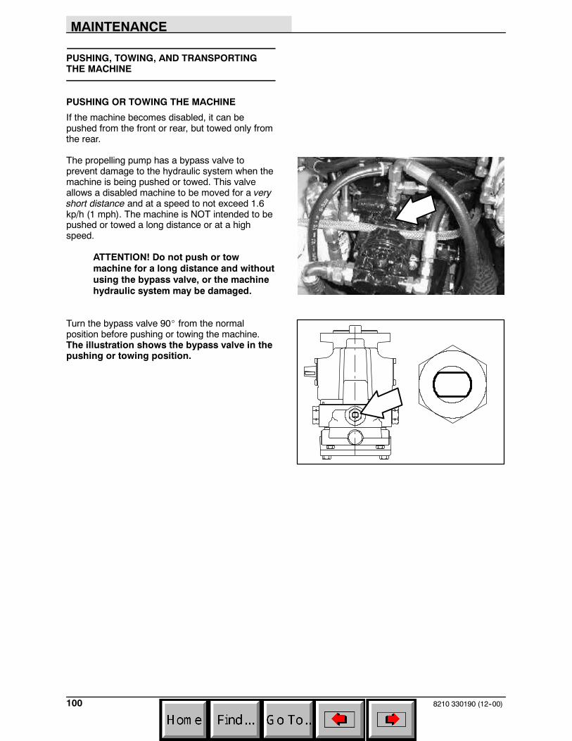
MAINTENANCE
8210 330190 (12--00)100
PUSHING, TOWING, AND TRANSPORTINGTHE MACHINE
PUSHING OR TOWING THE MACHINE
If the machine becomes disabled, it can bepushed from the front or rear, but towed only fromthe rear.
The propelling pump has a bypass valve toprevent damage to the hydraulic system when themachine is being pushed or towed. This valveallows a disabled machine to be moved for a veryshort distance and at a speed to not exceed 1.6kp/h (1 mph). The machine is NOT intended to bepushed or towed a long distance or at a highspeed.
ATTENTION! Do not push or towmachine for a long distance and withoutusing the bypass valve, or the machinehydraulic system may be damaged.
Turn the bypass valve 90_ from the normalposition before pushing or towing the machine.The illustration shows the bypass valve in thepushing or towing position.

MAINTENANCE
1018210 330190 (12--00)
TRANSPORTING THE MACHINE
1. Position the rear of the machine at theloading edge of the truck or trailer.
FOR SAFETY: Use truck or trailer thatwill support the weight of the machine.
NOTE: Empty the hopper, recovery tank, andsolution tank before transporting the machine.
2. If the loading surface is not horizontal or ishigher than 380 mm (15 in) from the ground,use a winch to load machine.
If the loading surface is horizontal AND is380 mm (15 in) or less from the ground, themachine may be driven onto the truck ortrailer.
3. To winch the machine onto the truck ortrailer, attach the winching chains to the reartie down locations. The rear tie-downlocations are the bottom lips at each cornerof the rear bumper.
4. Turn the bypass valve 90_ from the normalposition before winching the machine ontothe truck or trailer. See PUSHING ORTOWING THE MACHINE section of thismanual. Make sure the machine is centered.
FOR SAFETY: When loading machineonto truck or trailer, use winch. Do notdrive the machine onto the truck ortrailer unless the loading surface ishorizontal AND is 380 mm (15 in) or lessfrom the ground.
5. Position the machine onto the truck or traileras far as possible. If the machine starts toveer off the centerline of the truck or trailer,stop and turn the steering wheel to centerthe machine.

MAINTENANCE
8210 330190 (12--00)102
6. Set the parking brake, lower the scrub headand block the machine tires. Tie down themachine to the truck or trailer beforetransporting.
The front tie-down locations are the holes inthe wheel pockets at the front of themachine frame.
The rear tie-down locations are the bottomlips at each corner of the rear bumper.
7. If the loading surface is not horizontal or ishigher than 380 mm (15 in) from the ground,use a winch to unload machine.
If the loading surface is horizontal AND is380 mm (15 in) or less from the ground, themachine may be driven off the truck ortrailer.
FOR SAFETY: When unloading machineoff truck or trailer, use winch. Do notdrive the machine off the truck or trailerunless the loading surface is horizontalAND 380 mm (15 in) or less from theground.
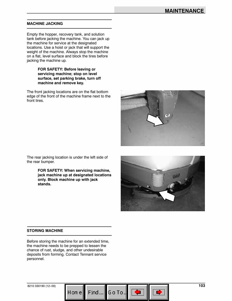
MAINTENANCE
1038210 330190 (12--00)
MACHINE JACKING
Empty the hopper, recovery tank, and solutiontank before jacking the machine. You can jack upthe machine for service at the designatedlocations. Use a hoist or jack that will support theweight of the machine. Always stop the machineon a flat, level surface and block the tires beforejacking the machine up.
FOR SAFETY: Before leaving orservicing machine; stop on levelsurface, set parking brake, turn offmachine and remove key.
The front jacking locations are on the flat bottomedge of the front of the machine frame next to thefront tires.
The rear jacking location is under the left side ofthe rear bumper.
FOR SAFETY: When servicing machine,jack machine up at designated locationsonly. Block machine up with jackstands.
STORING MACHINE
Before storing the machine for an extended time,the machine needs to be prepped to lessen thechance of rust, sludge, and other undesirabledeposits from forming. Contact Tennant servicepersonnel.
SPECIFICATIONS
8210 330190 (3--06)104
SPECIFICATIONS
GENERAL MACHINE DIMENSIONS/CAPACITIES
Item Dimension/capacity
Length 2550 mm (100.5 in)
Width with side brush 1395 mm (55 in)
Width with Maxpath side brush 1475 mm (58 in)
Height 1475 mm (58 in)
Height with overhead guard 2080 mm (82 in)
Track 1083 mm (42.6 in)
Wheelbase 1511 mm (59.5 in)
Main sweeping brush diameter 355 mm (14 in)
Main sweeping brush length 915 mm (36 in)
Scrub brush diameter -- 2 brushes 510 mm x 2 brushes (20 in x 2 brushes)
Scrub brush diameter -- 3 brushes (option) 410 mm x 3 brushes (16 in x 3 brushes) (option)
Side brush diameter 585 mm (23 in)
Sweeping path width 915 mm (36 in)
Sweeping path width with side brush 1270 mm (50 in)
Squeegee width 1219 mm (48 in)
Scrubbing path width -- two scrub brushes 1015 mm (40 in)
Scrubbing path width -- three scrub brushes(option)
1220 mm (48 in)
Main sweeping brush pattern width 64 mm (2.5 in) -- adjustable
Hopper weight capacity 160 kg (350 lb)
Hopper volume capacity 220 L (7.8 ft3)
Dust filter area 6 m2 (63 sq ft)
Solution tank 197 L (52 gal)
Recovery tank 265 L (70 gal)
Detergent tank 17.8 L (4.7 gal)
Total capacity with ES (option) 300 L (80 gal)
GVWR 1935 kg (4270 lb)
Ceiling height minimum dumping clearance 2286 mm (90 in )
GENERAL MACHINE PERFORMANCE
Item MeasureMaximum forward speed 10.0 kmh (6 mph)Maximum reverse speed 4.8 kmh (3 mph)Minimum aisle turn width, left 3.01 m (9 ft 9 in)Minimum aisle turn width, right 4.3 m (14 ft 10 in)Minimum turning radius, left 0.98 m (38.75 in)Minimum turning radius, right 1.91 m (75.25 in)Maximum rated incline for transport of machine (8_ -- 14%)Maximum rated incline for scrubbing/sweeping (6_ -- 10.5%)
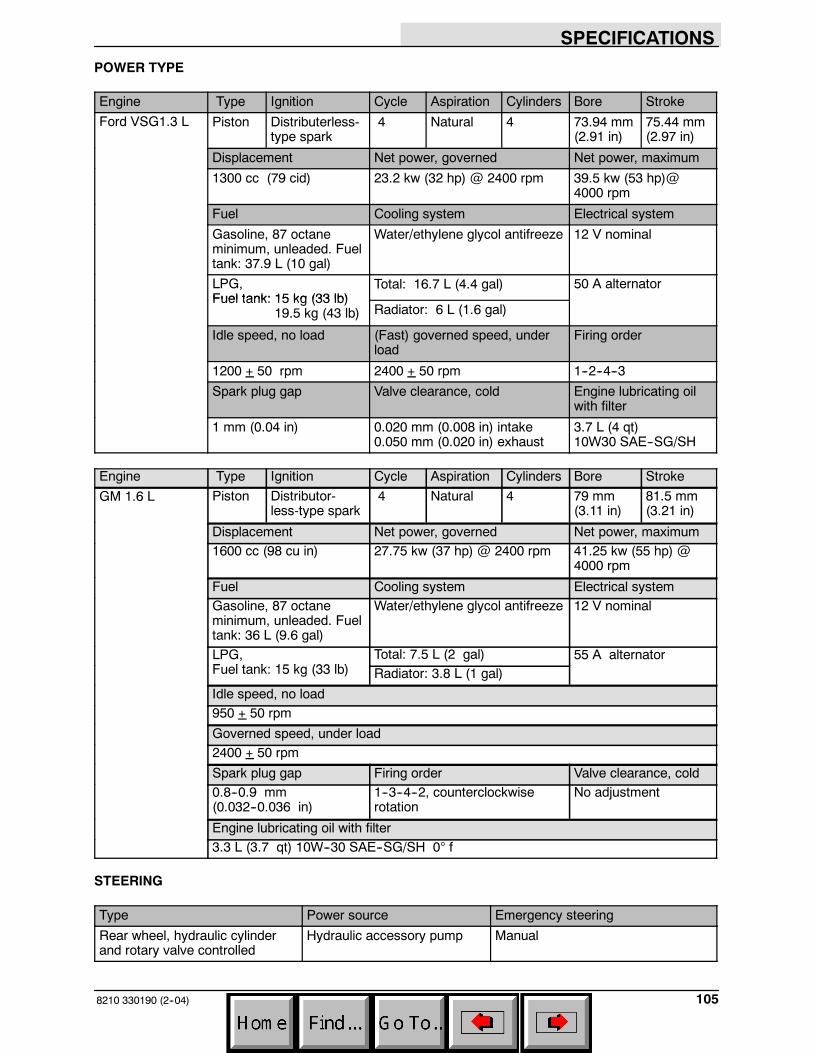
SPECIFICATIONS
1058210 330190 (2--04)
POWER TYPE
Engine Type Ignition Cycle Aspiration Cylinders Bore StrokeFord VSG1.3 L Piston Distributerless-
type spark4 Natural 4 73.94 mm
(2.91 in)75.44 mm(2.97 in)
Displacement Net power, governed Net power, maximum
1300 cc (79 cid) 23.2 kw (32 hp) @ 2400 rpm 39.5 kw (53 hp)@4000 rpm
Fuel Cooling system Electrical system
Gasoline, 87 octaneminimum, unleaded. Fueltank: 37.9 L (10 gal)
Water/ethylene glycol antifreeze 12 V nominal
LPG,Fuel tank: 15 kg (33 lb)
Total: 16.7 L (4.4 gal) 50 A alternatorFuel tank: 15 kg (33 lb)
19.5 kg (43 lb) Radiator: 6 L (1.6 gal)
Idle speed, no load (Fast) governed speed, underload
Firing order
1200 + 50 rpm 2400 + 50 rpm 1--2--4--3
Spark plug gap Valve clearance, cold Engine lubricating oilwith filter
1 mm (0.04 in) 0.020 mm (0.008 in) intake0.050 mm (0.020 in) exhaust
3.7 L (4 qt)10W30 SAE--SG/SH
Engine Type Ignition Cycle Aspiration Cylinders Bore StrokeGM 1.6 L Piston Distributor-
less-type spark4 Natural 4 79 mm
(3.11 in)81.5 mm(3.21 in)
Displacement Net power, governed Net power, maximum1600 cc (98 cu in) 27.75 kw (37 hp) @ 2400 rpm 41.25 kw (55 hp) @
4000 rpm
Fuel Cooling system Electrical systemGasoline, 87 octaneminimum, unleaded. Fueltank: 36 L (9.6 gal)
Water/ethylene glycol antifreeze 12 V nominal
LPG,F l t k 15 k (33 lb)
Total: 7.5 L (2 gal) 55 A alternator,Fuel tank: 15 kg (33 lb) Radiator: 3.8 L (1 gal)
Idle speed, no load950 + 50 rpm
Governed speed, under load2400 + 50 rpm
Spark plug gap Firing order Valve clearance, cold0.8--0.9 mm(0.032--0.036 in)
1--3--4--2, counterclockwiserotation
No adjustment
Engine lubricating oil with filter3.3 L (3.7 qt) 10W--30 SAE--SG/SH 0° f
STEERING
Type Power source Emergency steering
Rear wheel, hydraulic cylinderand rotary valve controlled
Hydraulic accessory pump Manual
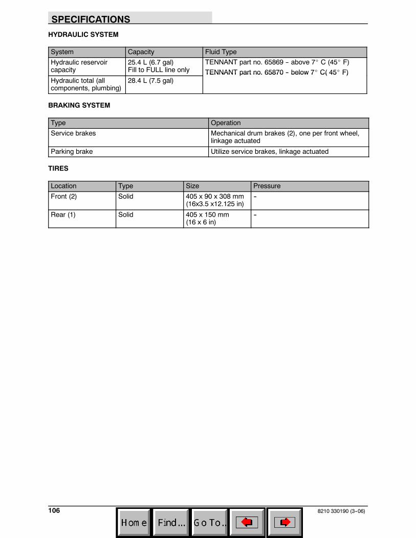
SPECIFICATIONS
8210 330190 (3--06)106
HYDRAULIC SYSTEM
System Capacity Fluid Type
Hydraulic reservoircapacity
25.4 L (6.7 gal)Fill to FULL line only
TENNANT part no. 65869 -- above 7_ C (45_ F)TENNANT part no. 65870 -- below 7_ C( 45_ F)
Hydraulic total (allcomponents, plumbing)
28.4 L (7.5 gal)TENNANT part no. 65870 below 7 C( 45 F)
BRAKING SYSTEM
Type Operation
Service brakes Mechanical drum brakes (2), one per front wheel,linkage actuated
Parking brake Utilize service brakes, linkage actuated
TIRES
Location Type Size Pressure
Front (2) Solid 405 x 90 x 308 mm(16x3.5 x12.125 in)
--
Rear (1) Solid 405 x 150 mm(16 x 6 in)
--

SPECIFICATIONS
1078210 330190 (3--06)
TOP VIEW
SIDE VIEW
2080 mm82 in
1395 mm55 in
2550 mm100.5 in
1083 mm42.6 in
351664MACHINE DIMENSIONS
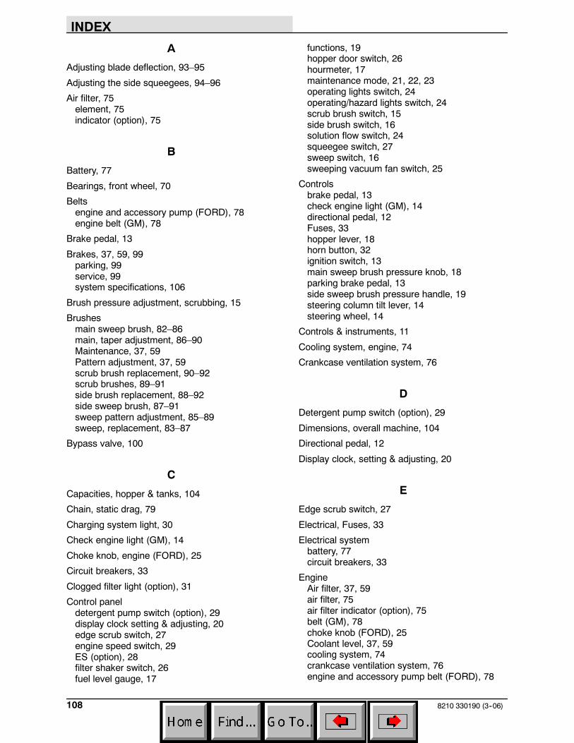
INDEX
8210 330190 (3--06)108
A
Adjusting blade deflection, 93–95
Adjusting the side squeegees, 94–96
Air filter, 75element, 75indicator (option), 75
B
Battery, 77
Bearings, front wheel, 70
Beltsengine and accessory pump (FORD), 78engine belt (GM), 78
Brake pedal, 13
Brakes, 37, 59, 99parking, 99service, 99system specifications, 106
Brush pressure adjustment, scrubbing, 15
Brushesmain sweep brush, 82–86main, taper adjustment, 86–90Maintenance, 37, 59Pattern adjustment, 37, 59scrub brush replacement, 90–92scrub brushes, 89–91side brush replacement, 88–92side sweep brush, 87–91sweep pattern adjustment, 85–89sweep, replacement, 83–87
Bypass valve, 100
C
Capacities, hopper & tanks, 104
Chain, static drag, 79
Charging system light, 30
Check engine light (GM), 14
Choke knob, engine (FORD), 25
Circuit breakers, 33
Clogged filter light (option), 31
Control paneldetergent pump switch (option), 29display clock setting & adjusting, 20edge scrub switch, 27engine speed switch, 29ES (option), 28filter shaker switch, 26fuel level gauge, 17
functions, 19hopper door switch, 26hourmeter, 17maintenance mode, 21, 22, 23operating lights switch, 24operating/hazard lights switch, 24scrub brush switch, 15side brush switch, 16solution flow switch, 24squeegee switch, 27sweep switch, 16sweeping vacuum fan switch, 25
Controlsbrake pedal, 13check engine light (GM), 14directional pedal, 12Fuses, 33hopper lever, 18horn button, 32ignition switch, 13main sweep brush pressure knob, 18parking brake pedal, 13side sweep brush pressure handle, 19steering column tilt lever, 14steering wheel, 14
Controls & instruments, 11
Cooling system, engine, 74
Crankcase ventilation system, 76
D
Detergent pump switch (option), 29
Dimensions, overall machine, 104
Directional pedal, 12
Display clock, setting & adjusting, 20
E
Edge scrub switch, 27
Electrical, Fuses, 33
Electrical systembattery, 77circuit breakers, 33
EngineAir filter, 37, 59air filter, 75air filter indicator (option), 75belt (GM), 78choke knob (FORD), 25Coolant level, 37, 59cooling system, 74crankcase ventilation system, 76engine and accessory pump belt (FORD), 78
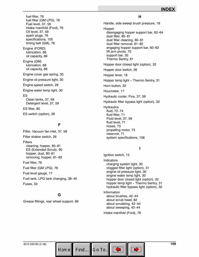
INDEX
1098210 330190 (3--06)
fuel filter, 76fuel filter (GM LPG), 76Fuel level, 37, 59intake manifold (Ford), 76Oil level, 37, 59spark plugs, 76specifications, 105timing belt (GM), 76
Engine (FORD)lubrication, 68oil capacity, 68
Engine (GM)lubrication, 68oil capacity, 68
Engine cover gas spring, 35
Engine oil pressure light, 30
Engine speed switch, 29
Engine water temp light, 30
ESClean tanks, 37, 59Detergent level, 37, 59
ES filter, 90
ES switch (option), 28
F
Filter, Vacuum fan inlet, 37, 59
Filter shaker switch, 26
Filterscleaning, hopper, 80–81ES (Extended Scrub), 90hopper, dust, 80–81removing, hopper, 81–82
Fuel filter, 76
Fuel filter (GM LPG), 76
Fuel level gauge, 17
Fuel tank, LPG tank changing, 38–40
Fuses, 33
G
Grease fittings, rear wheel support, 69
H
Handle, side sweep brush pressure, 19
Hopperdisengaging hopper support bar, 62–64dust filter, 80–81dust filter cleaning, 80–81dust filter removal, 81–82engaging hopper support bar, 60–62lift arm pivots, 70support bar, 35Thermo Sentry, 81
Hopper door closed light (option), 32
Hopper door switch, 26
Hopper lever, 18
Hopper temp light -- Thermo Sentry, 31
Horn button, 32
Hourmeter, 17
Hydraulic cooler, Fins, 37, 59
Hydraulic filter bypass light (option), 32
Hydraulicsfluid, 72–74fluid filter, 71Fluid level, 37, 59fluid level, 71hoses, 73propelling motor, 73reservoir, 71system specifications, 106
I
Ignition switch, 13
Indicatorscharging system light, 30clogged filter light (option), 31engine oil pressure light, 30engine water temp light, 30hopper door closed light (option), 32hopper temp light -- Thermo Sentry, 31hydraulic filter bypass light (option), 32
Informationabout brushes, 42–44about scrub head, 82about scrubbing, 42–44about sweeping, 42–44
Intake manifold (Ford), 76
INDEX
8210 330190 (3--06)110
J
Jack points, 103–105
K
Knob, main sweep brush pressure, 18
L
Latches, 35
Leveling rear squeegee, 92–94
Levershopper, 18steering column tilt, 14
Lightscharging system, 30check engine light (GM), 14clogged filter (option), 31engine oil pressure, 30engine water temperature, 30hopper door closed (option), 32hopper temperature -- Thermo Sentry, 31hydraulic filter bypass (option), 32
Lights switchoperating, 24operating/hazard, 24
LPG fuel system, tank changing, 38–40
Lubricationengine (FORD), 68engine (GM), 68front wheel bearings, 70rear wheel support, 69scrub head drag link arms, 70
M
Machine capabilitiesaisle turn dimensions, 104operating incline rate, 104travelling speeds, 104
Machine components, 8
Machine dimensions, illustrations, 107
Machine jacking, 103–105
Machine storage, 103
Machine tie down location, 102
Machine transport, tie downs, 63
Machine troubleshooting, 64–66
Main sweep brush, 82–86pattern, checking & adjustment, 85–89replacement, 83–87taper adjustment, 86–90
Main sweep brush pressure knob, 18
Maintenance, intervals chart, 66–68
Maintenance modedefinition, 21disabling, 23resetting timers, 22
Motors, propelling, hydraulic, 73
O
Operationscontrol panel functions, 19disengaging hopper support bar, 62–64double--scrubbing, 53–55draining & cleaning tanks, 54–56emptying the hopper, 46–48engaging hopper support bar, 60–62filling the tanks, 48–50how the machine works, 36LPG tank changing, 38–40on inclines, 63post--operation checklist, 59–61pre--operation checklist, 37–39scrubbing, 50–52starting the machine, 40–42stop scrubbing, 53–55stop sweeping, 45–47stopping the machine, 57–59sweeping, 44–46sweeping, scrubbing & brush info, 42–44
Operator responsibility, 7–8
Operator seat, 34suspension (option), 34
P
Parking brake pedal, 13
Pedalsbrake, 13directional, 12parking brake, 13
Pushing machine, 100
Pushing or towing the machine, 100
Pushing, towing, and transporting machine, 100
R
Radiator, Fins, 37, 59
Rear squeegee, 91–93adjusting blade deflection, 93–95blades, 94–96blades, rotation & replacement, 94–96leveling, 92–94
INDEX
1118210 330190 (3--06)
Rear wheel, 99
Recoevery tank, Drain and clean, 37, 59
Recovery tank, 90
S
Safetyengine cover gas spring, 35hopper support bar, 35labels, 5–7precautions, 3–5
Scrub brush pressure adjustment, 15
Scrub brush switch, 15
Scrub brushes, 89–91replacement, 90–92
Scrub functionsdouble--scrubbing, 53–55draining & cleaning tanks, 54–56filling the tanks, 48–50scrubbing, 50–52stop scrubbing, 53–55
Scrub head, 82
Scrub head drag link arms, 70
Seals, 96–100brush door, 96–100hopper, 97–101hopper door, 97–101hopper filter, 97–101hopper vacuum fan, 98–102Tank Cover, 37, 59tank covers, 98–102
Seat, suspension, (option), 34
Seat,, operator, 34
Service records, 37, 59
Side brush switch, 16
Side Squeegees, 94–98
Side squeegees, 95–97Adjusting the side squeegees, 94–96blade replacement, 95–97
Side sweep brush, 87–91replacement, 88–92
Side sweep brush pressure handle, 19
Skirts, 96–98hopper lip, 96rear, 96
Skirts and seals, 37, 59
Solution flow switch, 24
Solution flow valve, manual, 25
Solution tank, 91
Spark plugs, 76
Specificationsbraking system, 106engine power type, 105hydraulic system, 106machine capacities, 104machine dimensions, 104machine performance, 104machine weight, 104steering, 105tires, 106
Squeegee, Adjustment, 37, 59
Squeegee switch, 27
Squeegees, 91–93leveling, 92–94rear squeegee, 91–93rear, blade deflection, 93–95rear, blade rotation, 94–96rear, blades, 94–96side, 95–97Side Squeegees, 94side, blade replacement, 95–97
Static drag chain, 79
Steering, 37, 59specifications, 105
Steering column tilt lever, 14
Steering wheel, 14
Storing machine, 103
Super Scrub, 15, 51
Sweep brush, main, 82–86pattern, checking & adjustment, 85–89replacement, 83–87taper adjustment, 86–90
Sweep brush, side, 87–91replacement, 88–92
Sweep functionsemptying the hopper, 46–48stop sweeping, 45–47sweeping, 44–46
Sweep switch, 16
Switchdetergent pump (option), 29engine speed, 29filter shaker, 26hopper door, 26operating lights, 24operating/hazard lights, 24solution flow, 24vacuum fan, sweeping, 25
INDEX
8210 330190 (3--06)112
Switchesedge scrub, 27ES (option), 28ignition, 13scrub brush, 15side brush, 16squeegee, 27sweeping, 16
Symbol definitions, 9–11
T
Tanksrecovery tank, 90solution, 91
Thermo Sentry, 81
Tie down location, 102
Tie downs, 63
Timing Belt (GM), 76
Tires, 99rear wheel torque nuts, 99specifications, 106
Towing machine, 100
Transporting machine, 100
Transporting the machine, 101
Troubleshooting, 64–66
V
Vacuum fan switch, sweeping, 25
Valve, solution flow, 25