9/1/98 ac 150/5340-28 appendix 2 appendix 2. drawings. · 9/1/98 ac 150/5340-28 appendix 2 appendix...
TRANSCRIPT

9/1/98 AC 150/5340-28Appendix 2
APPENDIX 2. DRAWINGS.
1 (and 2)
FIGURE 1. TYPICAL TAXIWAY CENTERLINE LIGHTING CONFIGURATION FOR NON-STANDARD FILLETS.(Centerline light spacing for operations above 1,200 feet (365 m) RVR)

9/1/98 AC 150/5340-28Appendix 2
3
FIG
UR
E 2
. C
OL
OR
-CO
DIN
G O
F E
XIT
TA
XIW
AY
CE
NT
ER
LIN
E L
IGH
TS
AC 150/5340-28 9/1/98Appendix 2
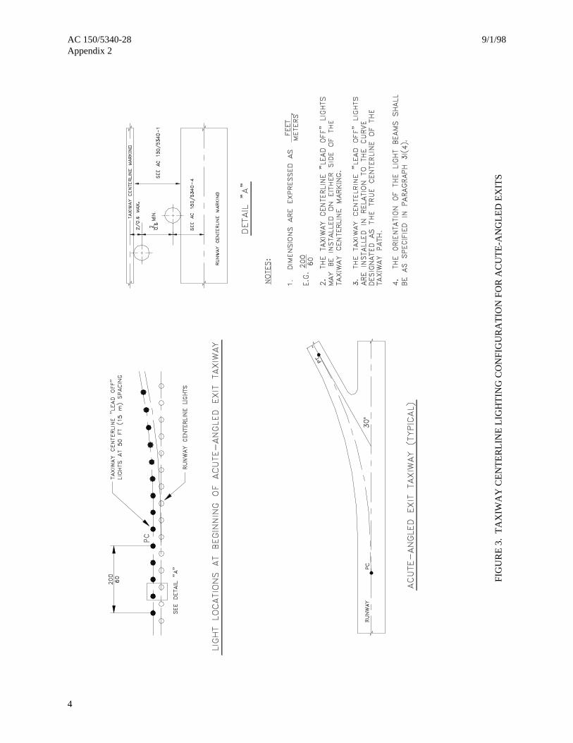
4
FIG
UR
E 3
. T
AX
IWA
Y C
EN
TE
RL
INE
LIG
HT
ING
CO
NFI
GU
RA
TIO
N F
OR
AC
UT
E-A
NG
LE
D E
XIT
S

9/1/98 AC 150/5340-28Appendix 2
5
FIG
UR
E 4
a. C
ON
TR
OL
LE
D S
TO
P B
AR
DE
SIG
N A
ND
OPE
RA
TIO
N

AC 150/5340-28 9/1/98Appendix 2
6
FIG
UR
E 4
b. C
ON
TR
OL
LE
D S
TO
P B
AR
DE
SIG
N A
ND
OPE
RA
TIO
N

9/1/98 AC 150/5340-28Appendix 2
7
FIG
UR
E 4
c. C
ON
TR
OL
LE
D S
TO
P B
AR
DE
SIG
N A
ND
OPE
RA
TIO
N
AC 150/5340-28 9/1/98Appendix 2
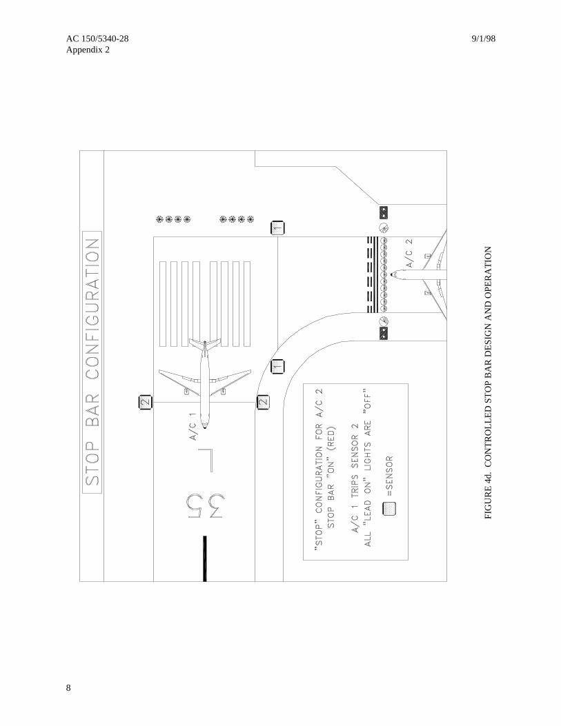
8
FIG
UR
E 4
d. C
ON
TR
OL
LE
D S
TO
P B
AR
DE
SIG
N A
ND
OPE
RA
TIO
N
9/1/98 AC 150/5340-28Appendix 2
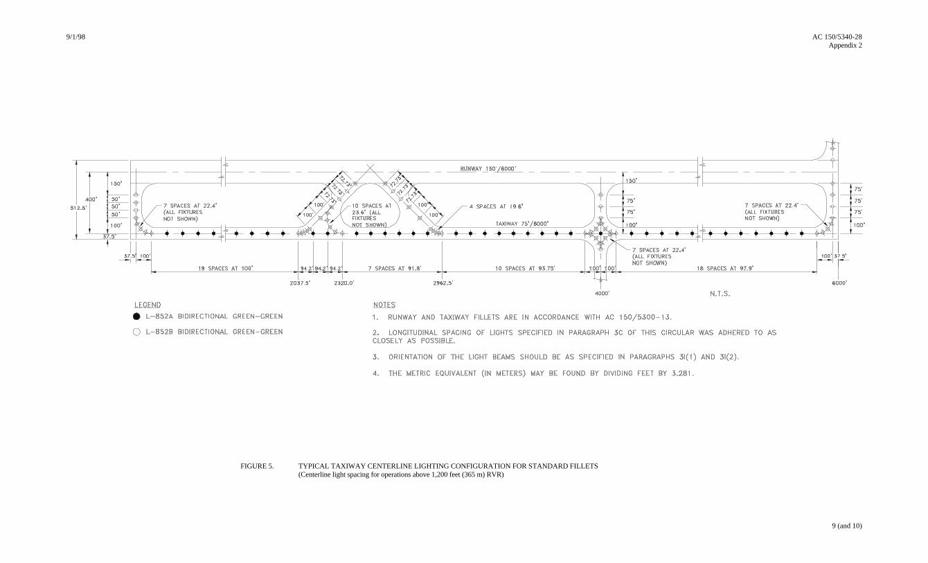
9 (and 10)
FIGURE 5. TYPICAL TAXIWAY CENTERLINE LIGHTING CONFIGURATION FOR STANDARD FILLETS(Centerline light spacing for operations above 1,200 feet (365 m) RVR)

9/1/98 AC 150/5340-28Appendix 2
11
FIG
UR
E 6
. T
AX
IWA
Y C
EN
TE
RL
INE
LIG
HT
BE
AM
OR
IEN
TA
TIO
N
AC 150/5340-28 9/1/98Appendix 2
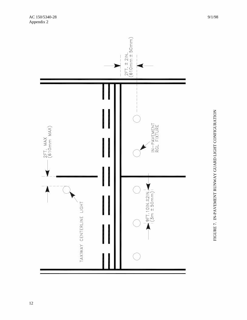
12
FIG
UR
E 7
. IN
-PA
VE
ME
NT
RU
NW
AY
GU
AR
D L
IGH
T C
ON
FIG
UR
AT
ION
9/1/98 AC 150/5340-28Appendix 2
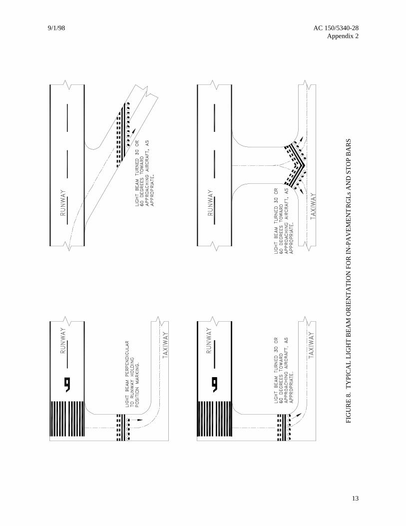
13
FIG
UR
E 8
. T
YPI
CA
L L
IGH
T B
EA
M O
RIE
NT
AT
ION
FO
R I
N-P
AV
EM
EN
T R
GL
s A
ND
ST
OP
BA
RS

AC 150/5340-28 9/1/98Appendix 2
14
FIG
UR
E 9
. E
LE
VA
TE
D R
GL
AN
D S
TO
P B
AR
LIG
HT
CO
NFI
GU
RA
TIO
N

9/1/98 AC 150/5340-28Appendix 2
15
FIGURE 10. CLEARANCE BAR CONFIGURATION AT A LOW VISIBILITY HOLD POINT

AC 150/5340-28 9/1/98Appendix 2
16
FIGURE 11. SAWING AND DRILLING DETAILS FOR IN-PAVEMENT TAXIWAYCENTERLINE LIGHTS

9/1/98 AC 150/5340-28Appendix 2
FIGURE 12. CURVES FOR ESTIMATING PRIMARY LOAD FOR TAXIWAY CENTERLINE LIGHTING SYSTEMS17 (and 18)
HOW TO OBTAIN THE 6.6 AMPERE PRIMARY KW LOADSAMPLE CALCULATIONS
1. Assumption. A taxiway centerline lighting configuration composed of 22 stations of four lights perstation spaced longitudinally at 100 feet as shown in Station “A” Flexible Pavement. Ten stations of 65Wwide-beam fixtures and twelve stations of 45W narrow-beam fixtures with a cable home-run separationdistance of 2,500 feet.
a. Total Lamp Secondary Watts.
10 stations x 4 lights/station x 65 watts/fixture = 2,600 watts12 stations x 4 lights/station x 45 watts/fixture = 2,160 watts
Total Lamp Secondary Watts = 4,760 watts
b. Total Lamp Primary Watts.
From Graph “A”, 4,760 watts total lamp secondary load equals 5.355 KW total lamp primary load.
c. Total Number feet of 10 AWG Secondary Cable.
From the configuration shown in Station “A” Flexible Pavement, we have a 300 foot longitudinal sawkerf, four vertical saw kerfs of 1 foot, one vertical saw kerf edge of taxiway pavement to the 300foot longitudinal saw kerf of 33.5 feet, and a distance of 10 feet from taxiway edge to the L-867 base(transformer housing).
300 foot longitudinal saw kerf x 2 (number of cables) = 600 feet1 foot vertical saw kerf x 4 (number of saw kerfs) x 2 (number of cables) = 8 feet33.5 foot vertical saw kerf x 1 (number of saw kerfs) x 2 (number of cables) = 67 feet10 feet taxiway edge to L-867 base x 1 (number of runs) x 2 (number of cables) = 20 feet
Total number of feet of Number 10 AWG cable used per station = 695 feet
695 feet Number 10 AWG cable per station x 22 stations = 15,290 feet total secondary cable.
d. Total Number 10 AWG Cable Primary KW Load.
From Graph “B”, 15,290 feet of Number 10 AWG secondary cable equals 0.677 KW primary load.
e. Total Number Feet Number 8 AWG Primary Cable.
22 stations, as show in Station “A” Flexible Pavement, has 21 spaces of 400 feet (separation betweenL-867 bases). Also, we have 2,500 feet home-run separation.
21 spaces x 400 feet separation x 2 (number of cables) = 16,800 feet2,500 feet (home-run separation) x 2 (number of cables) = 5,000 feet
Total number feet of Number 8 AWG primary cable = 21,800 feet
f. Total Number 8 AWG Cable Primary KW Load.
From Graph “B”, 21,800 feet Number 8 AWG primary cable equals 0.608 KW primary load.
g. Total 6.6 Ampere Primary KW Load.
Add total KW loads obtained in paragraphs b, d, and f above.
Paragraph b. = 5.355 KWParagraph d. = 0.677 KWParagraph f. = 0.608 KW
Total Primary KW load = 6.640 KW

9/1/98 AC 150/5340-28Appendix 2
19
FIG
UR
E 1
3.C
UR
VE
S FO
R D
ET
ER
MIN
ING
MA
XIM
UM
SE
PAR
AT
ION
BE
TW
EE
N V
AU
LT
AN
DC
ON
TR
OL
PA
NE
L W
ITH
120
-VO
LT
AC
CO
NT
RO
L

AC 150/5340-28 9/1/98Appendix 2
20
FIGURE 14. TYPICAL BASIC 120 VAC REMOTE CONTROL SYSTEM
9/1/98 AC 150/5340-28Appendix 2
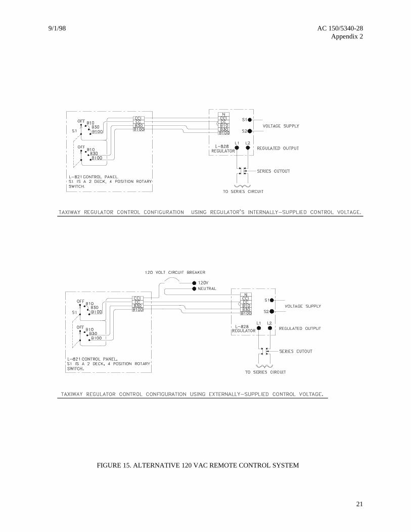
21
FIGURE 15. ALTERNATIVE 120 VAC REMOTE CONTROL SYSTEM