ac 150/5340-30a 11 april 2005 appendix 1 · ac 150/5340-30a 11 april 2005 appendix 1 100 100 4 m...
TRANSCRIPT
AC 150/5340-30A 11 April 2005 Appendix 1
100
100
4 mile radius
50 feet (+10, -0)
20 to30 feet
300 feetObstacle Clearance Surface (OCS) *
Lowest on-courseaiming angle *
Threshold CrossingHeight (TCH)Table 1.
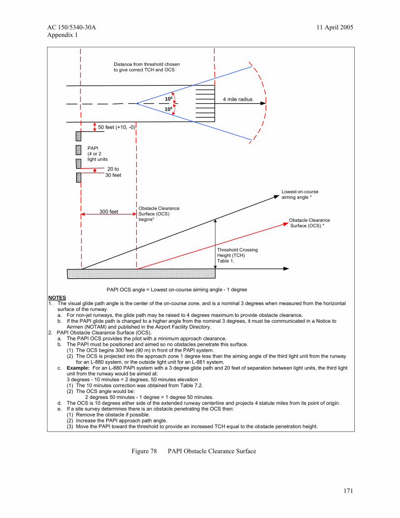
Distance from threshold chosento give correct TCH and OCS
PAPI(4 or 2light units
Obstacle ClearanceSurface (OCS)begins*
PAPI OCS angle = Lowest on-course aiming angle - 1 degreeNOTES 1. The visual glide path angle is the center of the on-course zone, and is a nominal 3 degrees when measured from the horizontal
surface of the runway. a. For non-jet runways, the glide path may be raised to 4 degrees maximum to provide obstacle clearance. b. If the PAPI glide path is changed to a higher angle from the nominal 3 degrees, it must be communicated in a Notice to
Airmen (NOTAM) and published in the Airport Facility Directory. 2. PAPI Obstacle Clearance Surface (OCS).
a. The PAPI OCS provides the pilot with a minimum approach clearance. b. The PAPI must be positioned and aimed so no obstacles penetrate this surface.
(1) The OCS begins 300 feet (90 m) in front of the PAPI system. (2) The OCS is projected into the approach zone 1 degree less than the aiming angle of the third light unit from the runway
for an L-880 system, or the outside light unit for an L-881 system. c. Example: For an L-880 PAPI system with a 3 degree glide path and 20 feet of separation between light units, the third light
unit from the runway would be aimed at: 3 degrees - 10 minutes = 2 degrees, 50 minutes elevation (1) The 10 minutes correction was obtained from Table 7.2. (2) The OCS angle would be:
2 degrees 50 minutes - 1 degree = 1 degree 50 minutes. d. The OCS is 10 degrees either side of the extended runway centerline and projects 4 statute miles from its point of origin. e. If a site survey determines there is an obstacle penetrating the OCS then:
(1) Remove the obstacle if possible. (2) Increase the PAPI approach path angle. (3) Move the PAPI toward the threshold to provide an increased TCH equal to the obstacle penetration height.
Figure 78 PAPI Obstacle Clearance Surface
171
11 April 2005 AC 150/5340-30A Appendix 1
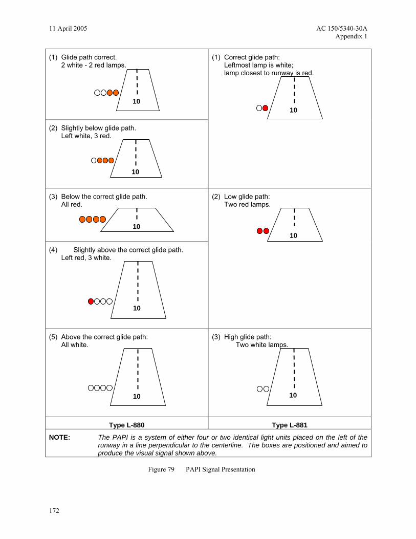
(1) Glide path correct. 2 white - 2 red lamps.
(2) Slightly below glide path. Left white, 3 red.
(1) Correct glide path: Leftmost lamp is white; lamp closest to runway is red.
(3) Below the correct glide path. All red.
(4) Slightly above the correct glide path. Left red, 3 white.
(2) Low glide path: Two red lamps.
(5) Above the correct glide path: All white.
(3) High glide path: Two white lamps.
Type L-880 Type L-881
NOTE: The PAPI is a system of either four or two identical light units placed on the left of the runway in a line perpendicular to the centerline. The boxes are positioned and aimed to produce the visual signal shown above.
Figure 79 PAPI Signal Presentation
10
10
10
10 10
10
10 10
172
AC 150/5340-30A 11 April 2005 Appendix 1
Reference Plane
RRP
RWY TCH
T d
D1 Ideal RRP
e
θ
Aiming angle or visual approach path
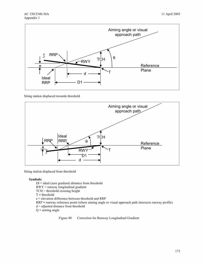
Siting station displaced towards threshold
e
Ideal RRP Reference
Plane
RRP
RWY
TCH
T D1
d
θ
Aiming angle or visual approach path
Siting station displaced from threshold
Symbols: Dl = ideal (zero gradient) distance from threshold RWY = runway longitudinal gradient TCH = threshold crossing height T = threshold e = elevation difference between threshold and RRP RRP = runway reference point (where aiming angle or visual approach path intersects runway profile) d = adjusted distance from threshold Q = aiming angle
Figure 80 Correction for Runway Longitudinal Gradient
173
11 April 2005 AC 150/5340-30A Appendix 1
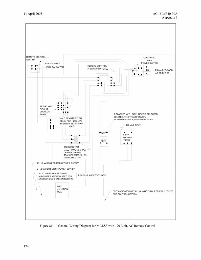
Figure 81 General Wiring Diagram for MALSF with 120-Volt, AC Remote Control
174

AC 150/5340-30A 11 April 2005 Appendix 1
Figure 82 Typical Wiring Diagram for MALSF Controlled from Runway Lighting Circuit
175

11 April 2005 AC 150/5340-30A Appendix 1
Figure 83 Typical Field Wiring Circuits for MALSF
176

AC 150/5340-30A 11 April 2005 Appendix 1
Figure 84 Typical Installation Details for Frangible MALS Structures – 6 foot Maximum
177

11 April 2005 AC 150/5340-30A Appendix 1
Figure 85 Typical Wiring for REILs Multiple Operation
178

AC 150/5340-30A 11 April 2005 Appendix 1
Figure 86 Typical Wiring for REILs Series Operation
179

11 April 2005 AC 150/5340-30A Appendix 1
Figure 87 FAA L-880 Style B (Constant Current) System Wiring Diagram
180

AC 150/5340-30A 11 April 2005 Appendix 1
Figure 88 FAA L-880 Style A (Constant Voltage) System Wiring Diagram
181
11 April 2005 AC 150/5340-30A Appendix 1
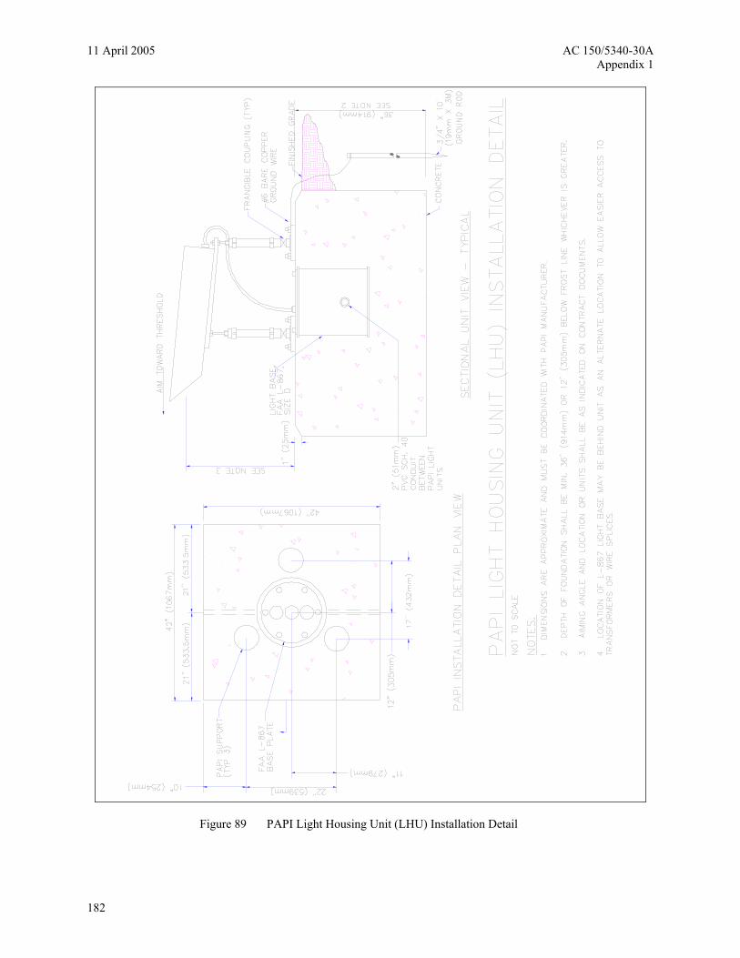
Figure 89 PAPI Light Housing Unit (LHU) Installation Detail
182
AC 150/5340-30A 11 April 2005 Appendix 1
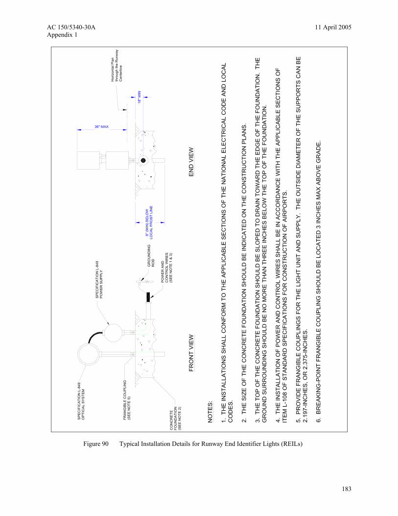
Figure 90 Typical Installation Details for Runway End Identifier Lights (REILs)
183

11 April 2005 AC 150/5340-30A Appendix 1
Figure 91 Configuration “A” Electrical Power
184

AC 150/5340-30A 11 April 2005 Appendix 1
Figure 92 Typical KVA Input Requirements
185

11 April 2005 AC 150/5340-30A Appendix 1
Figure 93 Typical Wiring Diagram for Configuration “A” Electrical Power
186

AC 150/5340-30A 11 April 2005 Appendix 1
Figure 94 Typical Equipment Layout for Configuration “A” Electrical Power
187

11 April 2005 AC 150/5340-30A Appendix 1
Figure 95 Configuration “B” Electrical Power
188

AC 150/5340-30A 11 April 2005 Appendix 1
Figure 96 Typical Wiring Diagram for Configuration “B” Electrical Power
189
11 April 2005 AC 150/5340-30A Appendix 1
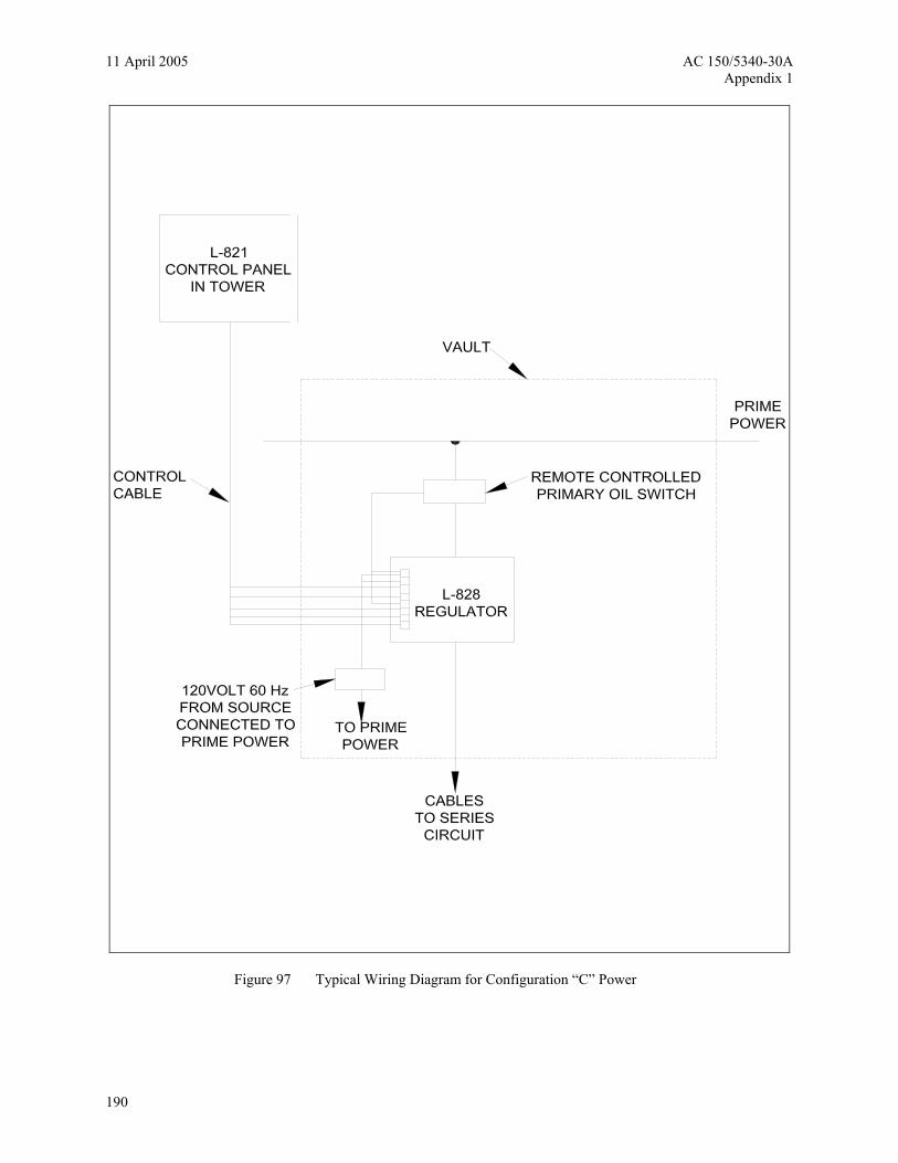
Figure 97 Typical Wiring Diagram for Configuration “C” Power
190

AC 150/5340-30A 11 April 2005 Appendix 1
Figure 98 Flexible Pavement or Overlay Installation
191

11 April 2005 AC 150/5340-30A Appendix 1
Not
es:
1. 2. 3.
Pos
ition
the
base
to p
erm
it pa
ssag
e of
pav
ing
mac
hine
an
d to
acc
omod
ate
flang
e rin
g an
d fix
ture
.
Thic
ker f
lang
e rin
gs o
r spa
cer r
ings
may
be
used
for
corre
ctin
g sp
acin
g. H
owev
er, p
ositi
onin
g th
e ba
se to
o hi
gh m
ay re
sult
in a
mor
e co
stly
cor
rect
ive
actio
n.
In s
ettin
g th
e ba
se e
leva
tion,
allo
w fo
r at l
east
1/2
inch
(1
3 m
m) v
aria
tion
in th
eore
tical
pav
emen
t sur
face
el
evat
ion
plus
1/4
inch
(6 m
m) a
dditi
onal
saf
ety
mar
gin.
Pave
men
t Sur
face
Bel
ow T
heor
etic
al3"
(76
mm
) (ap
prox
.)
N.T
.S.
Cov
er /
Spa
cers
(as
requ
ired)
(102
mm
)(1
52 m
m)
(305
mm
)
(76
mm
)3"
BAS
EL-
868
(see
not
es)
Ele
vatio
n is
crit
ical
Alig
nmen
t Jig
MIN
.
Con
duit
Ope
ning
Anc
hor R
ing
(Opt
iona
l)
Cag
e #4
Bar
s
VA
RIE
S
12" M
INIM
UM
6" M
INIM
UM
4"
Legs
Adj
ustm
ent
Sub
base
Com
pact
ed
Ste
el R
einf
orce
men
t
Figure 99 Use of Alignment Jig, No Reference Edge Available, Non-adjustable Base and Conduit System
192

AC 150/5340-30A 11 April 2005 Appendix 1
(see
not
es)
Ele
vatio
n is
crit
ical
Alig
nmen
t Jig
MIN
.
Con
duit
Ope
ning
Anch
or R
ing
(Opt
iona
l)
Cag
e #4
Bar
s
VAR
IES
12" M
INIM
UM
6" M
INIM
UM
4"
Pav
emen
tE
xist
ing
Sub
base
Com
pact
ed
Ste
el R
einf
orce
men
t
Not
es:
1. 2. 3.
Pos
ition
the
base
to p
erm
it pa
ssag
e of
pav
ing
mac
hine
an
d to
acc
omod
ate
flang
e rin
g an
d fix
ture
.
Thic
ker f
lang
e rin
gs o
r spa
cer r
ings
may
be
used
for
corre
ctin
g sp
acin
g. H
owev
er, p
ositi
onin
g th
e ba
se to
o hi
gh m
ay re
sult
in a
mor
e co
stly
cor
rect
ive
actio
n.
In s
ettin
g th
e ba
se e
leva
tion,
allo
w fo
r at l
east
1/2
inch
(1
3 m
m) v
aria
tion
in th
eore
tical
pav
emen
t sur
face
el
evat
ion
plus
1/4
inch
(6 m
m) a
dditi
onal
saf
ety
mar
gin.
Pav
emen
t Sur
face
Bel
ow T
heor
etic
al3"
(76
mm
) (ap
prox
.)
N.T
.S.
Cov
er /
Spa
cers
(as
requ
ired)
(102
mm
)(1
52 m
m)
(305
mm
)
(76
mm
)3"
BA
SE
L-86
8
Figure 100 Use of Alignment Jig, Reference Edge Available, Non-adjustable Base and Conduit System
193

11 April 2005 AC 150/5340-30A Appendix 1
Figure 101 In-pavement Shallow Base Runway Edge End or Threshold Light
194

AC 150/5340-30A 11 April 2005 Appendix 1
Figure 102 In-pavement Shallow Base Runway Centerline or TDZ Light
195
11 April 2005 AC 150/5340-30A Appendix 1
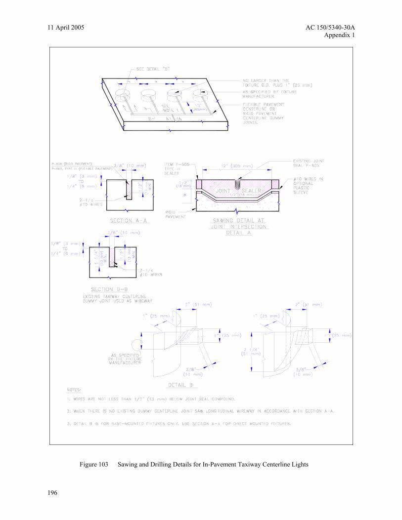
Figure 103 Sawing and Drilling Details for In-Pavement Taxiway Centerline Lights
196

AC 150/5340-30A 11 April 2005 Appendix 1
Figure 104 Wiring Details for Direct- and Base-Mounted Taxiway Centerline Lights
197
11 April 2005 AC 150/5340-30A Appendix 1
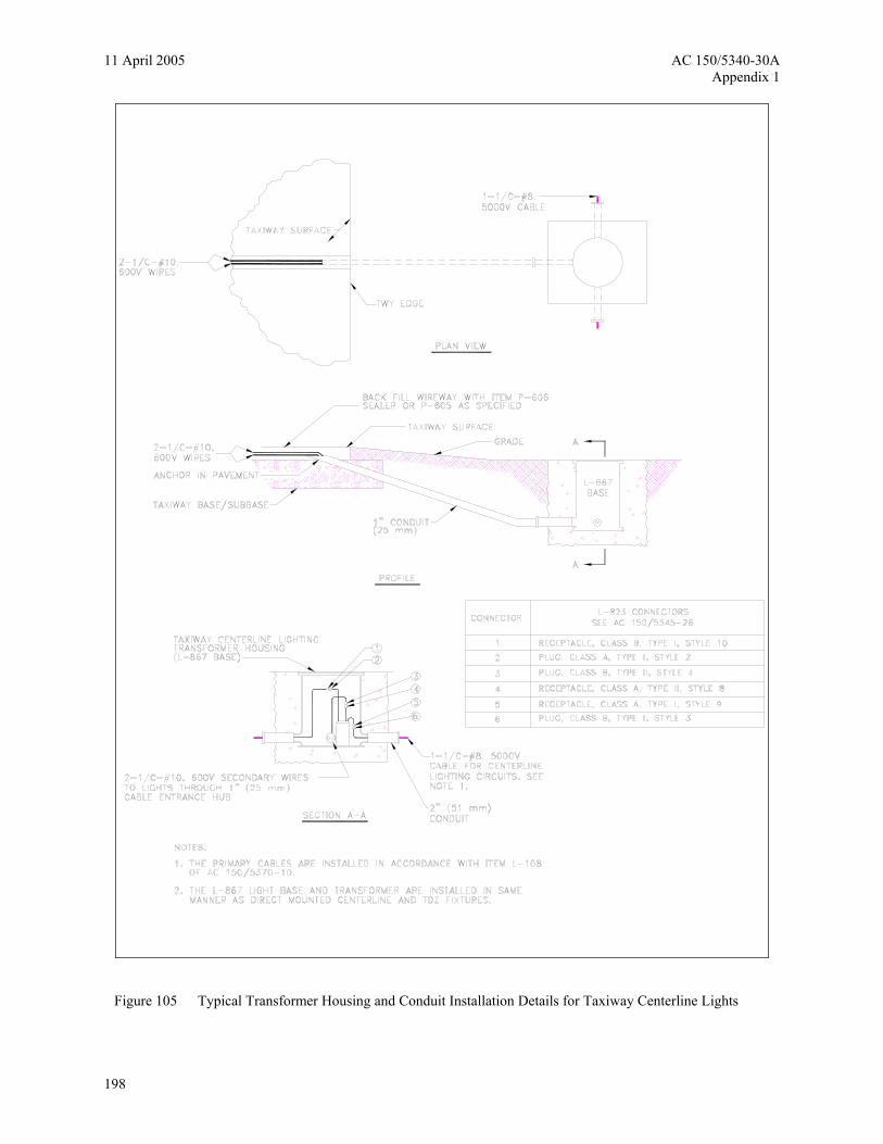
Figure 105 Typical Transformer Housing and Conduit Installation Details for Taxiway Centerline Lights
198

AC 150/5340-30A 11 April 2005 Appendix 1
Not
es:
Whe
n lig
hts
are
elev
ated
abo
ve 1
4 in
. (st
anda
rd),
a m
inim
um c
lear
ance
of 6
" (15
cm
) mus
t be
mai
ntai
ned
betw
een
the
fixtu
re a
nd a
ny o
verh
angi
ng p
art o
f an
airc
raft.
In th
is a
rea
the
max
imum
fix
ture
hei
ght i
s 14
inch
es.
5' (1
.5 m
)
Pav
emen
t Edg
e(o
r Def
ined
Run
way
Edg
e)
5'14" In
this
are
a, th
e fix
ture
hei
ght m
ay
be in
crea
sed
2 in
ches
per
foot
. Th
e m
axim
um fi
xtur
e he
ight
10
ft fro
m
the
taxi
way
edg
e is
30
inch
es a
bove
gr
ade.
10' (
3 m
)
7'6'
8'9'
10'
20"
18"
16"
22"
24"-
30"
Figure 106 Adjustment of Edge Light Elevation for High Snowfall Areas
199
11 April 2005 AC 150/5340-30A Appendix 1
NOT TO SCALE
ARROW TO INDICATEDIRECTION OF CABLE RUN
CABLE
1/2' STROKE LETTERS IMPRESSED1/4' INTO CONCRETE
CABLE AND DUCT MARKERS
NOTES:
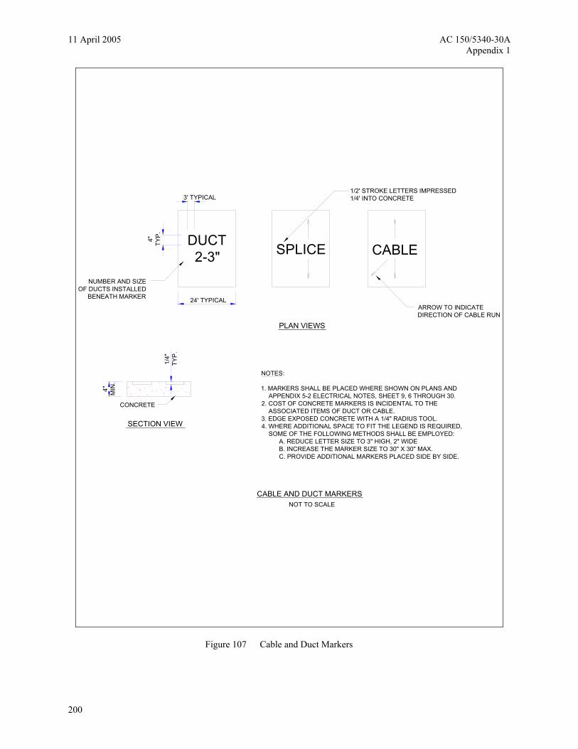
1. MARKERS SHALL BE PLACED WHERE SHOWN ON PLANS AND APPENDIX 5-2 ELECTRICAL NOTES, SHEET 9, 6 THROUGH 30.2. COST OF CONCRETE MARKERS IS INCIDENTAL TO THE ASSOCIATED ITEMS OF DUCT OR CABLE.3. EDGE EXPOSED CONCRETE WITH A 1/4" RADIUS TOOL.4. WHERE ADDITIONAL SPACE TO FIT THE LEGEND IS REQUIRED, SOME OF THE FOLLOWING METHODS SHALL BE EMPLOYED: A. REDUCE LETTER SIZE TO 3" HIGH, 2" WIDE B. INCREASE THE MARKER SIZE TO 30" X 30" MAX. C. PROVIDE ADDITIONAL MARKERS PLACED SIDE BY SIDE.
SPLICE
PLAN VIEWS
SECTION VIEW
CONCRETE
4" MIN
.
1/4"
TYP.
NUMBER AND SIZEOF DUCTS INSTALLED
BENEATH MARKER 24' TYPICAL
DUCT2-3"
4" TYP
.
3' TYPICAL
Figure 107 Cable and Duct Markers
200
AC 150/5340-30A 11 April 2005 Appendix 1
GROUND RODNOT TO SCALE
NOTES:
1- TYPE AND MINIMUM NUMBER OF GROUND RODS SHALL BE AS SPECIFIED ON THE PLAN.
2- THE RESISTANCE TO GROUND OF THE COUNTERPOISE GROUNDING SYSTEM SHALL NOT EXCEED 25 OHMS.
3- COST OF GROUND RODS IS INCIDENTAL TO THE ASSOCIATED ITEMS REQUIRING GROUNDING UNLESS OTHERWISE SPECIFIED.
5/8" X 8' MIN. GROUND RODCOPPERWELD OR EQUAL
#6, BARE, SOLID,COPPER COUNTERPOISE
EXOTHERMIC WELDED CONNECTION
FINSHED GRADE
8"
6"
LIGHT AND INSTALLATION DETAIL
FULL STRENGTHPAVEMENT EDGE
I/C,#8.5KV L-824TYPE C CABLE
PROFILE VIEW
8"
6' 4'
#6 BARE COUNTERPOISE WITH 5/8" X 8' GROUND ROD INSTALLED AT MAX. 500'SPACING. ALSO USE GROUND ROD TO TERMINATE THE COUNTERPOISE AT BOTHENDS OF DUCT
18"
TYPICAL ELEVATED LIGHT
2'
COUNTERPOISE
10'
1'
L-830 TRANSFORMER
3' OF SLACK MIN. IN EACHPRIMARY CABLE. BEND RADIUS10° MIN.
1'
COUNTERPOISE
GROUND ROD
2'
5'
5'DUCT
EDGE OF PAVEMENT
TYPICAL LIGHT
L-830 TRANSFORMER
I/C,#8.5KV L-824TYPE C CABLE
PLAN VIEW
COUNTERPOISE
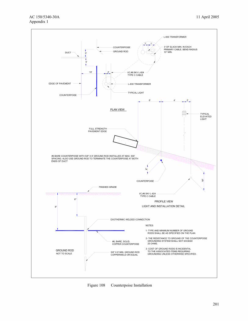
Figure 108 Counterpoise Installation
201
11 April 2005 AC 150/5340-30A Appendix 1
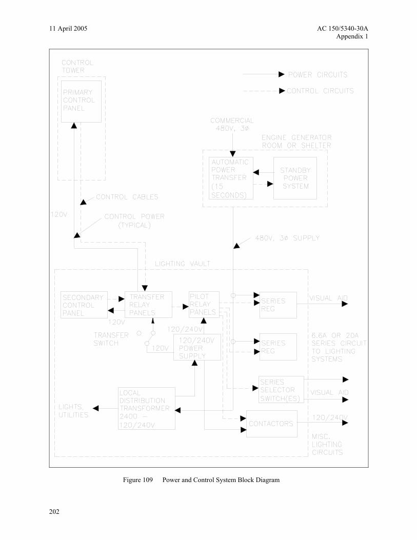
Figure 109 Power and Control System Block Diagram
202

AC 150/5340-30A 11 April 2005 Appendix 1
Figure 110 Typical PLC Control System Block Diagram
203
11 April 2005 AC 150/5340-30A Appendix 1
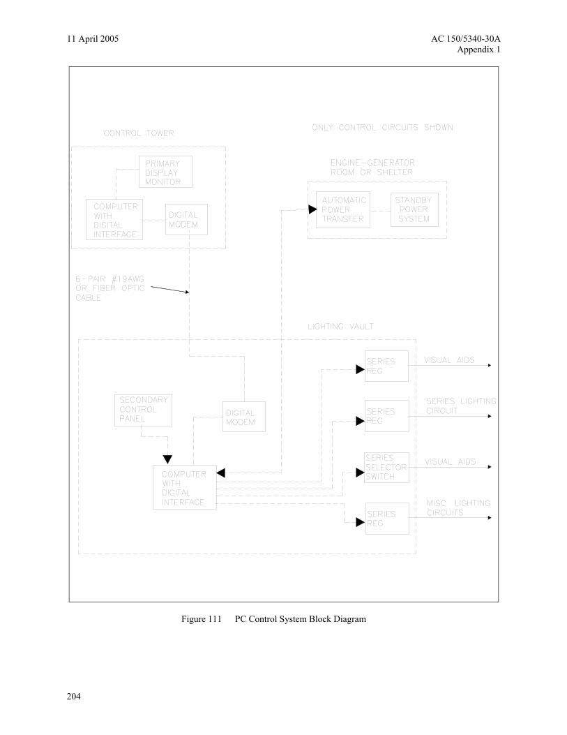
Figure 111 PC Control System Block Diagram
204
AC 150/5340-30 11 April 2005 Appendix 2
APPENDIX 2 – AIRPORT TECHNICAL ADVISORY
Subject: Electromagnetic interference (EMI) induced by L-828, SCR Type, Constant Current Regulators (CCRs).
Some airports have experienced excessive levels of EMI which degrades the performance of some of the airport’s air navigational systems, i.e. RVRs, glide slope localizers, ATCTS, etc., SCR type, L-828, CCRs, are the likely sources of EMI due to their inherent operating characteristics. The following are some of the cautionary steps that may help decrease EMI and/or its adverse effects in the airport environment.
1. Cables for airfield lighting circuits should not be installed in the same conduit, cable duct or duct bank as control and communication cables.
2. Cables for airfield lighting systems should not be installed such that they cross control and/or communications cables.
3. In some cases, harmonic filters may be installed at the regulator output to reduce the EMI emitted by the CCR. These filters are available from some CCR manufacturers.
4. Spare control and communications cables should be grounded.
5. Inform manufacturers, designers, engineers, etc., about the existing navigational equipment and the potential for interference.
6. Electromagnetic compatibility between new equipment and existing equipment should be a requirement in project contracts. Operational acceptance test(s) may be required to verify compliance.
The FAA is modifying AC 150/5345-10E, Specification for Constant Current Regulators and Regulator Monitors to decrease EMI in the airport environment.
For more information contact the FAA Office of Airport Safety and Standards, FAA Engineering, 800 Independence Avenue, S.W.,Washington D.C. 20591.
.
205

11 April 2005 AC 150/5340-30 Appendix 2
Intentionally left blank.
206

AC 150/5340-30 11 April 2005 Appendix 3
APPENDIX 3 - TERMS & ACRONYMS
AC Advisory Circular or Alternating Current
Accelerate-stop distance available
The runway plus stopway length declared available and suitable for the acceleration and deceleration of an airplane aborting a takeoff
AIP Airport Improvement Program
ALD Available Landing Distance
ALS Approach Lighting System
ALSF Approach Lighting System with Sequenced Flashing Lights
ANSI American National Standards Institute
ASDA Accelerated-stop distance available
ASTM American Society for Testing and Materials
ATC Air Traffic Control
ATCT Air Traffic Control Tower
CAN/CSA Canadian Standards Association
CAT I Facility providing operation down to 200 feet decision height and runway visual range not less than 2400 feet
CAT II Facility providing operation down to 100 feet decision height and runway visual range not less than 1200 feet
CAT III Facility providing operation with no decision height limit and along the surface of the runway with external visual reference during final phase of landing and with a runway and runway visual range not less than 600 feet, down to 0.
CCR Constant Current Regulator
Cd Candela (a unit of luminous intensity)
CL Center Line
CTAF Common Traffic Advisory Frequency
DC Direct Current
DEB Direct Earth Burial
Declared Distances The distances declared available and suitable for satisfying the airplane takeoff run, takeoff distance, accelerate-stop distances, and landing distance requirements. The distances are ASDA, LDA, TORA and TODA.
207

11 April 2005 AC 150/5340-30 Appendix 3
Displaced Threshold A threshold that is located at a point on the runway other than the designated beginning of the runway.
DWG Drawing
E-982 Steady-burning Approach Lights
EMI Electromagnetic Interference
EMT Electro-Mechanical Tubing
FAA Federal Aviation Administration
HIRL High Intensity Runway Edge Lights
I/O Input/Output
ICEA Insulated Cable Engineers Association
IEEE Institute of Electrical and Electronics Engineers
IFR Instrument Flight Rules
ILS Instrument Landing System
ISO International Standards Organization
KV Kilovolt
KVA Kilovolt Ampere
KW Kilowatt
L-850C Style 3 Flush in-pavement light fixture
L-852D Taxiway centerline for CAT III
L-852E, F Runway Guard Light in-pavement
L-852G Combination Runway Guard
L-852G/S Combination Runway Guard/Stop Bar Light in-pavement
L-852S Stop Bar Light in-pavement
L-853 Reflective Markers
L-854 Radio Controller (Pilot Controlled Lights)
L-858R, Y, L, B Guidance Signs
L-860 Low-Intensity Elevated Light
L-861 Medium-Intensity Elevated Runway/Taxiway Light
208

AC 150/5340-30 11 April 2005 Appendix 3
L-862 High-Intensity Elevated Runway Edge Light
L-867 Non-load Bearing Base Cans
L-868 Load Bearing Base Cans
L-880/ L-881 Precision Approach Path Indicators (PAPI)
L-884 Land and Hold Short Operations (LAHSO) Power Control Unit (PCU)
LAHSO Land and Hold Short Operations
Landing Distance Available
The runway length declared available and suitable for a landing aircraft.
LDA Landing Distance Available
LDIN Lead-In Lighting System
LHU Light Housing Unit
LIRL Low Intensity Runway Edge Lights
MALS Medium-intensity Approach Lighting System
MALSF Medium-intensity Approach Lighting System with Sequenced Flashers
MALSR Medium-intensity Approach Lighting System with Runway Alignment Indicator Lights
MIRL Medium Intensity Runway Edge Lights
MITL Medium Intensity Taxiway Lights
MLS Microwave Landing System
NAS National Airspace System
NEC National Electrical Code
NEMA National Electrical Manufacturers Association
NFPA National Fire Protection Association
Non-precision Approach Runway
Runway with only horizontal guidance available
Non-precision Instrument Runway
A runway having an existing instrument approach procedure utilizing air navigation facilities with only horizontal guidance for which a straight-in or side-step non-precision approach procedure has been approved.
NOTAM Notice To Airmen
NRTL Nationally Recognized Testing Laboratory
209

11 April 2005 AC 150/5340-30 Appendix 3
OCS Obstacle Clear Surface
OFZ Obstacle Free Zone
OSHA Occupational Safety and Health Administration
PAPI Precision Approach Path Indicator
PAR Precision Approach Radar
PC Point of Curvature
PCU Power and Control Unit
PLC Programmable Logic Controllers
Precision Approach Runway
Full instrument approach procedure and equipment available (ILS or MLS)
Precision Instrument Runway
A runway having an existing instrument approach procedure utilizing air navigation facilities with both horizontal and vertical guidance for which a precision approach procedure has been approved.
PT Point of Tangency
RCL Runway Centerline Lighting
REIL Runway End Identifier Lights
RGL Runway Guard Lights
ROFA Runway Object Free Area
RPZ Runway Protection Zone
RSA Runway Safety Area
RSAT Runway Safety Action Team
Runway Object Free Area An area on the ground centered on a runway provided to enhance the safety of aircraft operations by having the area free of objects, except for objects that need to be located in the OFA for air navigation or aircraft ground maneuvering purposes.
Runway Protection Zone An area off the runway end used to enhance the protection of people and property on the ground.
Runway Safety Area A defined surface surrounding the runway prepared or suitable for reducing the risk of damage to airplanes in the event of an undershoot, overshoot, or threshold.
RVR Runway Visual Range
SCR Silicon Controlled Rectifier
SMGCS Surface Movement Guidance and Control System
210
AC 150/5340-30 11 April 2005 Appendix 3
SPDT Single Pole Double Throw
Takeoff distance available The TORA plus the length of any remaining runway and/or clearway beyond the far end of the TORA.
Takeoff runway available The runway length declared available and suitable for the ground run of an airplane taking off.
TDZ Touchdown Zone
Threshold A line perpendicular to the runway centerline marking the beginning of the runway surface available for a landing.
TODA Takeoff distance available
TORA Takeoff run available
UL Underwriter’s Laboratory
UPS Uninterruptible Power Supply
VAC Voltage Alternating Current
VDC Voltage Direct Current
VFR Visual Flight Rules
Visual Runway Runway with no instrument approach procedure/equipment
VMC Visual Meteorological Conditions
211

11 April 2005 AC 150/5340-30 Appendix 3
Intentionally left blank.
212
AC 150/5340-30 11 April 2005 Appendix 4
APPENDIX 4 - BIBLIOGRAPHY
1. AC 00-2, Federal Register, Advisory Circular Checklist and Status of Federal Aviation Regulations (FAR), updated triannually, contains the listing of all current issuances of ACs and changes thereto. It explains the circular numbering system and gives instructions for ordering ACs that are for sale as well as those distributed free of charge. AC 00-2 also gives instructions for ordering the Federal Aviation Regulations.
a. FAA Advisory Circulars. Copies of the current edition of the AC may be obtained at no charge from the FAA Website at: http://www2.faa.gov/arp/150acs.cfm
Department of Transportation General Services Paragraph M443.2 Washington, DC 20590
(1) AC 70/7460-1, Obstruction Marking and Lighting.
(2) AC 120-28, Criteria for Approval of Category III Landing Weather Minima
(3) AC 120-29, Criteria for Approval of Category I and Category II Landing Minima for Approach.
(4) AC 120-57, Surface Movement Guidance and Control System (SMGCS).
(5) AC 150/5000-3, Address List for Regional Airports Divisions and Airports District Offices.
(6) AC 150/5000-13, Announcement of Availability--RTCA Inc., Document RTCA-221, Guidance and Recommended Requirements for Airport Surface Movement Sensors.
(7) AC 150/5200-30, Airport Winter Safety and Operations.
(8) AC 150/5300-13, Airport Design
(9) AC 150/5340-1, Standards for Airport Markings
(10) AC 150/5340-9, Standard Specification for Construction of Airports
(11) AC 150/5340-26, Maintenance of Airport Visual Aid Facilities
(12) AC 150/5345-3, Specification for L-821 Airport Lighting Panel for Control of Airport Lighting.
(13) AC 150/5345-5, Circuit Selector Switch.
(14) AC 150/5345-7, Specification for L-824 Underground Electrical Cable for Airport Lighting Circuits.
(15) AC 150/5345-10, Specification for Constant Current Regulators Regulator Monitors.
(16) AC 150/5345-12, Specification for Airport and Heliport Beacons.
(17) AC 150/5345-13, Specification for L-841 Auxiliary Relay Cabinet Assembly for Pilot Control of Airport Lighting Circuits.
(18) AC 150/5345-26, Specification for L-823 Plug and Receptacle, Cable Connectors.
213

11 April 2005 AC 150/5340-30 Appendix 4
(19) AC 150/5345-27, Specification for Wind Cone Assemblies.
(20) AC 150/5345-28, Precision Approach Path Indicator (PAPI) Systems
(21) AC 150/5345-39, FAA Specification L-853, Runway and Taxiway Retroreflective Markers.
(22) AC 150/5345-42, FAA Specification L-867, L-868, Airport Light Bases, Transformer Housing, Junction Boxes, and Accessories.
(23) AC 150/5345-43, Specification for Obstruction Lighting Equipment.
(24) AC 150/5345-46, Specification for Runway and Taxiway Light Fixtures.
(25) AC 150/5345-47, Isolation Transformers for Airport Lighting Systems.
(26) AC 150/5345-49, Specification L-854, Radio Control Equipment.
(27) AC 150/5345-50, Specification for Portable Runway Lights
(28) AC 150/5345-51, Specification for Discharge-Type Flasher Equipment.
(29) AC 150/5345-53, Airport Lighting Equipment Certification Program.
(30) AC 150/5345-54, Specification for L-884 Power and Control Unit for Land and Hold Short Lighting Systems.
(31) AC 150/5345-XX, Specification for L-890 Airport Lighting Control and Monitoring Systems (ALCMs)
(32) AC 150/5370-2, Operational Safety on Airports During Construction.
(33) AC 150/5370-10, Standards for Specifying Construction of Airports.
b. Electronic copies of FAA Standards may be obtained from: http://204.108.10.116/nasiHTML/FAAStandards/
(1) FAA Order 7110.118, Land and Hold Short Operations (LAHSO).
(2) FAA Order 6030.20A, Electrical Power Policy
(3) FAA Order 6850.2, Visual Guidance Lighting Systems
(4) FAA Order 6950.11, Reduced Electrical Power Interruptions at FAA Facilities
(5) FAA Order 6950.27, Short Circuit Analysis and Protective Device Case Study
c. FAA drawings may be obtained from:
FAA William J. Hughes Technical Center NAS Documentation Facility, ACK-1 Atlantic City International Airport New Jersey, 08405
214

AC 150/5340-30 11 April 2005 Appendix 4
(1) FAA DWG C-6046, Frangible Coupling Type I and Type IA, Details.
(2) Engineering Brief #61, Installation Procedures for Adjustable Light Bases and Extensions
(3) FAA-C-1391, Installation and Splicing of Underground Cable
(4) FAA-E-2083, Bypass Switch, Engine Generator
(5) FAA-E-2204, Diesel Engine Generator Sets, 10kw to 750kw
(6) FAA-E-2325, Medium Intensity Approach Lighting System with Runway Alignment Indicator Lights
(7) 14 CFR part 77, Objects Affecting Navigable Airspace
(8) 14 CFR part 139, Certifications and Operations; Land Airports Serving Certain Air Carriers
d. Electronic copy of the Aeronautical Information Manual (AIM) may be obtained from: http://www.faa.gov/Atpubs/AIM/index.htm
2. Federal Specifications. Copies of Federal specifications may be obtained at no charge from: General Services Administration Offices in Washington, DC, and other cities. For access to Federal Specifications go to: http://www.gsa.gov/Portal/gsa/ep/contentView.do?contentId=10766&contentType=GSA_BASIC
U.S. General Services Administration 1800 F Street, NW Washington, DC 20405
a. Federal Specification J-C-145, Cable, Power, Electrical and Wire, Electrical (Weather-Resistant)
b. Federal Specification TT-P-28, Paint, Aluminum, Heat Resisting (1200 Deg. F.)
c. FED-STD-595, Colors Used in Government Procurement
3. American Society for Testing and Materials (ASTM) Specifications, Test Methods, Standard Practices, and Recommended Practices. Copies of ASTM specifications, test methods, and recommended practices may be obtained from: American Society for Testing and Materials. Contact them at: http://www.astm.org
American Society for Testing and Materials 1916 Race Street Philadelphia, PA 19103
a. ASTM C-892, Standard Specification for High Temperature Fiber Blanket Thermal Insulation
b. ASTM D-3407, Standard Test Method for Joint Sealants, Hot Poured, for Concrete and Asphalt Pavements
c. ASTM Specification A-53, Standard Specification for Pipe, Steel, Black and Hot-Dipped, Zinc-coated, Welded and Seamless
d. ASTM-A184, Standard Specification for Fabricated Deformed Steel Bar Mats for Concrete Reinforcement
e. ASTM-A704, Standard Specification for Welded Steel Plain Bar or Rod Mats for Concrete Reinforcement
215
11 April 2005 AC 150/5340-30 Appendix 4
4. National Fire Protection Association: Copies of the National Electrical Code (NFPA 70) can be obtained:
http://www.nfpa.org/Codes/index.asp .
NFPA 1 Batterymarch Park Quincy, Massachusetts USA 02169-7471
5. American National Standards Institute (ANSI). Copies of ANSI standards may be obtained from the National Standards Institute. Contact them at: http://www.ansi.org
ANSI 1819 L Street, NW, 6th floor Washington, DC 20036
a. ANSI/ICEA S-85-625, Telecommunications Cable Air Core, Polyolefin Insulated, Copper Conductor, Technical Requirements
216
AC 150/5340-30 11 April 2005 Appendix 5
APPENDIX 5 – TYPICAL INSTALLATION DRAWINGS FOR AIRPORT LIGHTING EQUIPMENT
The following drawings depict typical installation methods for various types of airport lighting equipment and are acceptable for use on projects funded under the AIP. However, the drawings may need to be revised to accommodate local site conditions and/or special requirements. Figures are typical non-proprietary equipment. Other equipment, such as adjustable cans, is acceptable. Details of equipment and installation methods will be provided by manufacturers.
217

11 April 2005 AC 150/5340-30 Appendix 5
FRANGIBLE COUPLING
COVER BOLTS (TYP.)
FINISHED GRADE
COLOR CODED TAPE FOR WIRE IDENTIFICATION
LOCATED WITHIN 6" OF L-823 CONNECTOR
PVC CONDUIT FROM CAN TOLIGHT CAN (IN & OUT) 2"
LD. MIN. CONDUIT SHALL BECROWNED TO A NOMINAL 1%
SLOPE FOR DRAINAGE 2.5"
L-830 TRANSFORMER, SIZE AS REQUIREDTO SERVE FIXTURE
L-867 BASE, 24" DEEP ON 6" MIN. SAND BACKFILL
PROVIDE 3 FEET MIN. OF SLACK IN EACHPRIMARY CABLE
BRICK
6" MIN. SAND BACKFILL
3/4" DIA. WEEP HOLE
NOT TO SCALE
HIGH INTENSITY LIGHT - BASE MOUNTED(WHEN CONDUIT IS USED BETWEEN CANS)
VIEW IS PERPENDICULAR TO RWY. EDGE
I/C, #8.5KV L-824 TYPE C
CABLE
L-861 OR L-862 AS SHOWN ONLIGHTING LAYOUT SHEET(S)
I.D. TAG
SECONDARY LEAD WITHCONNECTOR
SLOPE TO DRAIN AWAY FROM LIGHT
L-823 CONNECTOR
30" CONCRETE BACKFILL, 4" MIN.
Figure 112 Typical Standard Details for Runway & Taxiway Edge Lights –High Intensity Light – Non-adjustable Base-mounted
218

AC 150/5340-30 11 April 2005 Appendix 5
FRANGIBIE COUPLING
COVER BOLTS (TYP.)
FINISHED GRADE
L-861 OR L-862 AS SHOWN ONLIGHTING LAYOUT SHEET(S)
I.D. TAG
PAVEMENT EDGE
L-823 CONNECTOR
L-830 TRANSFORMER, SIZE AS REQUIREDTO SERVE FIXTURE
PROVIDE 3 FEET MIN. OF SLACK IN EACHPRIMARY CABLE
MIN.
BRICK
3/4" DIA. WEEP HOLE
6" MIN. SAND BACKFILL
I/C, #8.5KV L-824 TYPE CCABLE 18" BELOW GRADE
VIEW IS PARALLEL TO RUNWAY EDGENOT TO SCALE
MEDIUM / HIGH INTENSITY LIGHT - BASE MOUNTED
COLOR CODED TAPE FOR WIRE IDENTIFICATIONLOCATED WITHIN 6" OF L-823 CONNECTOR
L-867 BASE
4"
TO
CONCRETE BACKFILL, 4" MIN.
SLOPE TO DRAIN AWAY FROM LIGHT
SECONDARY LEAD WITHCONNECTOR
Figure 113 Typical Standard Details for Runway & Taxiway Edge Lights –Medium / High Intensity Light – Non-adjustable Base-mounted
219

11 April 2005 AC 150/5340-30 Appendix 5
I.D. TAG
30° SECONDARY LEAD WITH
CONNECTOR
CLIP (DO NOT USE)
L-823 CONNECTORS
30° ANGLE IRON STAKE
10"
18"
I/C, #8.5KV L-824TYPE C CABLE
ENCASE TRANSFORMER, CONNECTORSAND CABLE SLACK IN SAND
FRANGIBLE COUPLING
COLOR CODED TAPE FOR WIRE IDENTIFICATIONLOCATED WITHIN 6" OF L-823 CONNECTOR
MEDIUM INTENSITY LIGHT - STAKE MOUNTED
PAVEMENT EDGE
TO
FINISHED GRADE
L-861 OR L-862 AS SHOWN ONLIGHTING LAYOUT SHEET(S)
12"
FRANGIBLE COUPLING
L-830 TRANSFORMER SIZE AS REQUIREDTO SERVE THE FIXTURE LOCATED 12'
OUTBOARD OF LIGHT
Figure 114 Typical Standard Details for Runway & Taxiway Edge Lights –Medium Intensity Light – Stake-mounted
220

AC 150/5340-30 11 April 2005 Appendix 5
GROUND RODNOT TO SCALE
NOTES:
1- TYPE AND MINIMUM NUMBER OF GROUND RODS MUST BE AS SPECIFIED ON THE PLAN.
2- THE RESISTANCE TO GROUND OF THE COUNTERPOISE GROUNDING SYSTEM MUST NOT EXCEED 25 OHMS.
3- COST OF GROUND RODS IS INCIDENTAL TO THE ASSOCIATED ITEMS REQUIRING GROUNDING UNLESS OTHERWISE SPECIFIED.
5/8" X 8' MIN. GROUND RODCOPPERWELD OR EQUAL
#6, BARE, SOLID,COPPER COUNTERPOISE
EXOTHERMIC WELDED CONNECTION
FINISHED GRADE
8"
6"
Figure 115 Typical Standard Details for Runway and Taxiway Edge Lights –Ground Rod
221
11 April 2005 AC 150/5340-30 Appendix 5
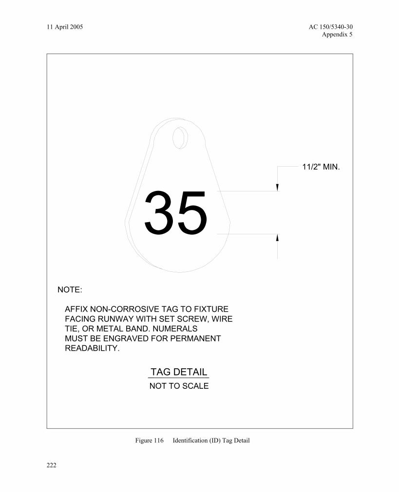
NOTE:
AFFIX NON-CORROSIVE TAG TO FIXTURE FACING RUNWAY WITH SET SCREW, WIRE TIE, OR METAL BAND. NUMERALS MUST BE ENGRAVED FOR PERMANENT READABILITY.
NOT TO SCALETAG DETAIL
3511/2" MIN.
Figure 116 Identification (ID) Tag Detail
222

AC 150/5340-30 11 April 2005 Appendix 5
TYPICAL ELEVATED LIGHT
4'
COUNTERPOISE
GROUND ROD
2'
5'
5'DUCT
EDGE OF PAVEMENT
FULL STRENGTHPAVEMENT EDGE
TYPICAL LIGHT
L-830 TRANSFORMER
I/C,#8.5KV L-824TYPE C CABLE
PLAN VIEW
18"
#6 BARE COUNTERPOISE WITH 5/8" X 8' GROUND ROD INSTALLED AT MAX. 500'SPACING. ALSO USE GROUND ROD TO TERMINATE THE COUNTERPOISE AT BOTHENDS OF DUCT
8"
I/C,#8.5KV L-824TYPE C CABLE
PROFILE VIEW
LIGHT AND INSTALLATION DETAIL
GENERAL NOTES
1. SEE LIGHTING LAYOUT SHEET FOR LIGHT LOCATIONS
2. SEE APPENDIX 5-2 FOR ELECTRICAL NOTES
COUNTERPOISE
2'6'
10'
1'
L-830 TRANSFORMER
3' OF SLACK MIN. IN EACHPRIMARY CABLE. BEND RADIUS10° MIN.
1'
Figure 117 Tyical Standard Details for Runway and Taxiway Edge Lights –Light & Installation Detail
223

11 April 2005 AC 150/5340-30 Appendix 5
COMPACTED SAND BACKFILLBETWEEN DUCT BANKS
TYPICAL MULTIPLE BANK LAYOUT
3" TYP.
3" TYP.
NOTES:
1- DUCTS MUST BE CROWNED TO A NORMAL 1% SLOPE FOR DRAINAGE.
2- DUCTS ARE 3" UNLESS OTHERWISE SPECIFIED
3- NUMBER OF BANKS AND CONFIGURATION AS SPECIFIED ON THE PLANS.
3" SAND BED
6" COMPACTED COVER
DUCT
COMPACTEDBACKFILL
SPACERS WIRED IN PLACE HORIZONTALLY TOMAINTAIN 3 INCH SPACING.
Figure 118 Standard Details for Underground Cable Installation –Typical Multiple Bank Layout
224
AC 150/5340-30 11 April 2005 Appendix 5
24" MIN.N
OT
TO S
CA
LEU
ND
ER
GR
OU
ND
ELE
CTR
ICA
L D
UC
T
BA
CK
FILL
CO
MP
AC
TED
TO M
AIN
TAIN
3"
VE
RTI
CA
L S
EP
AR
ATI
ON
SPA
CE
RS
6"MIN.
#10
DR
AG W
IRE.
CO
IL A
MIN
IMU
M O
F 3'
AT
DU
CT
EN
DS
. IN
STA
LL W
OO
DE
NP
LUG
S IN
EN
DS
OF
DU
CTS
NO
T U
SED
6"
PA
VE
ME
NT
ED
GE
SUR
FAC
E C
OU
RSE
DU
CT
MA
RKE
R
SUB-
BASE
BASE
CO
UR
SE
2'-6
"
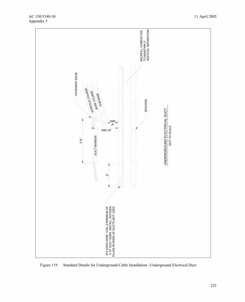
Figure 119 Standard Details for Underground Cable Installation –Underground Electrical Duct
225

11 April 2005 AC 150/5340-30 Appendix 5
FOR
SP
LIC
ES
IN H
OM
ER
UN
S A
ND
FO
R E
XTEN
SIO
NS
T
O E
XIS
TIN
G C
AB
LE O
NLY
TYPE
A
CO
MPR
ES
SIO
N T
YP
E S
LEEV
EC
ON
NEC
TOR
. CR
IMP
WIT
H T
OO
LR
EC
OM
ME
ND
ED
BY
MA
NU
FAC
TUR
ER
RE
SIN
SE
AL
EN
DS
OF
MO
LDW
ITH
TA
PE
PR
OV
IDE
DIN
SP
LIC
E K
IT
PO
UR
ING
SP
OU
TP
LAS
TIC
BOD
Y M
OLD
CA
BLE
JA
CK
ET R
EMO
VE
D,
"PE
NC
IL" I
NS
ULA
TIO
N
Figure 120 Standard Details for Underground Cable Installation –Type A
226

AC 150/5340-30 11 April 2005 Appendix 5
HEA
T S
HR
INK
ABLE
TU
BIN
GW
ITH
INTE
RN
AL
ADH
ES
IVE
UN
DE
RG
RO
UN
D C
AB
LES
PEC
. L-8
24, T
YP
ICA
L
FOR
SPL
ICE
S F
OR
US
E A
T JU
NC
TIO
N O
F
HO
ME
RU
N W
ITH
LO
OP
CIR
CU
IT
TYP
E B
RE
CE
PTA
CLE
EN
DP
LUG
EN
D
HE
AT S
HR
INK
ABLE
TU
BIN
GW
ITH
INTE
RN
AL
AD
HE
SIV
EA
DD
ITIO
NAL
AD
HE
SIV
EC
OM
PO
UN
D F
ILLE
R
WR
AP W
ITH
AT
LEA
ST
ON
E L
AY
ER O
F R
UBB
ER
OR
SYN
THE
TIC
RU
BB
ERTA
PE
AN
D O
NE
LAY
ER
OF
PLA
STI
C T
APE
, ON
E-H
ALF
LAP
PPE
D,
EX
TEN
DIN
G A
T LE
AS
T 1
1/2
INC
HES
ON
EAC
H S
IDE
OF
JOIN
T.
TYP.
2" A
FTE
R S
HR
INK
ING
Figure 121 Standard Details for Underground Cable Installation –Type B
227

11 April 2005 AC 150/5340-30 Appendix 5
HE
AT S
HR
INK
ABLE
TU
BIN
GW
ITH
INTE
RN
AL
ADH
ESIV
E
WR
AP
WIT
H A
T LE
AS
T O
NE
LAY
ER
OF
RU
BBE
R O
R S
YNTH
ETIC
RU
BBE
RTA
PE
AN
D O
NE
LAY
ER
OF
PLA
STI
C T
APE
, ON
E-H
ALF
LA
PPE
D,
EX
TEN
DIN
G A
T LE
AS
T 1
1/2
INC
HE
S O
N E
AC
H S
IDE
OF
JOIN
T.
AD
DIT
ION
AL
AD
HE
SIVE
CO
MPO
UN
D F
ILLE
R
WR
AP
WIT
H A
T LE
AS
T O
NE
LA
YE
R O
F R
UB
BER
OR
SY
NTH
ETI
C R
UB
BER
TAP
E A
ND
ON
E L
AYE
R O
F P
LAS
TIC
TA
PE,
ON
E-H
ALF
LAP
PPE
D,
EX
TEN
DIN
G A
T LE
AS
T 1
1/2
INC
HE
S O
N E
ACH
SID
E O
F JO
INT.
L-82
3 P
LUG
EN
D
NO
TES
:
1. S
EE
LIG
HTI
NG
LA
YOU
T S
HE
ET(
S) F
OR
SP
LIC
E TY
PE
2. IN
SID
E D
IAM
ETE
R O
F C
ON
NE
CTO
R S
HA
LL P
RO
PER
LYM
ATC
H T
HE
OU
TSID
E D
IAM
ETE
R O
F C
ABL
E
CAB
LE S
PLIC
ES
FOR
SP
LIC
ES
AT
RU
NW
AY
LIG
HTS
TYP
E C
AD
DIT
ION
AL
ADH
ESIV
EC
OM
PO
UN
D F
ILLE
RR
EC
EP
TAC
LE E
ND
FAC
TOR
Y M
OLD
ED
TRA
NS
FOR
MER
LEA
DS
FAC
TOR
Y M
OLD
ED
TRA
NS
FOR
ME
R L
EA
DS
RE
CE
PTA
CLE
EN
D
HE
AT
SH
RIN
KA
BLE
TU
BIN
GW
ITH
INTE
RN
AL A
DH
ESI
VE
PLU
G E
ND
NO
T TO
SC
ALE
Figure 122 Standard Details for Underground Cable Installation –Type C
228

AC 150/5340-30 11 April 2005 Appendix 5
Figure 123 Standard Details for Underground Cable Installation –Plowed Cable
229

11 April 2005 AC 150/5340-30 Appendix 5
PLOWED CABLE
6. THE COUNTERPOISE TO BE ABOVE CABLES ONLY WHERE
5. ALL DISTURBED SURFACES MUST BE RESTORED TO THEIR
4. SAND BACKFILL MAY BE WAIVED BY THE ENGINEER
EARTH BACKFILL
1' MAX SIZE
SAND BACKFILL100% PASSINGNO. 8 SIEVE
EARTH BACKFILL
1' MAX SIZEPARTICLES
UNLESS OTHERWISE SPECIFIED ON THE PLANS. 3. DEPTH OF TRENCHES SHALL BE SHOWN ABOVE
TWO PARALLEL TRENCHES MAY BE CONSTRUCTED. ADDITIONAL CABLE. IF SPECIFIED ON PLANS. INCREASED 3" IN WIDTH FOR EACH
2. TRENCHES MORE THAN 7 CABLES MUST BE
1. DETAIL NUMBERS INDICATE NO. OF CABLES.
5
18' 6'
18"
6
SAND BACKFILL100% PASSING
NO. 8 SIEVE
(TY
P.)
4" TOP SOL.SEED & MULCH
18" 6" 4"
TY
PIC
AL
FOR
1 A
ND
2 C
ABL
ES
SAND
1 2
CO
UN
TER
PO
ISE
3" (TYP.)
OF COUNTERPOISE RUN PAVEMENT SEE FIGURE 117. THE CABLES ARE NOT ADJACENT TO PAVEMENT. FOR LOCATION
MATERIALS AND RATES MAY BE SHOWN ON THE PLAN. ORIGINAL CONDITION. COST IS INCIDENTAL TO TRENCH RETURFING
IF THE EXISTING SOIL MEETS THE BACKFILL REQUIREMENTS.
7
CO
UN
TER
PO
ISE
CABLES
3 4
6" T
YP
ICA
L FO
R 3
AN
D M
OR
E C
AB
LES
21" 24"
15"12"9"6"
3" (TYP.)3" (TYP.)
3" (TYP.)3" (TYP.)
(TY
P.)
(TY
P.)
(TY
P.)
3" (TYP.)
Figure 124 Standard Details for Underground Cable Installation –Plowed Cable
230

AC 150/5340-30 11 April 2005 Appendix 5
NO
T TO
SC
ALE
SIG
N -
SIN
GLE
PE
DE
STA
L
3/4"
DIA
. WEE
P H
OLE
CO
LOR
CO
DE
D T
AP
E F
OR
WIR
E ID
EN
TIFI
CA
TIO
NLO
CA
TED
WIT
HIN
6" O
F L-
823
CO
NN
EC
TOR
I/C,#
8.5K
V L-
824
TYPE
CC
AB
LE 1
8' B
ELO
W G
RA
DE
FIN
ISH
ED
GR
AD
E
L-82
3 C
ON
NE
CTO
RS
L-86
7 B
AS
E O
N 6
" MIN
. SA
ND
BA
CK
FILL
L-83
0 TR
AN
SFO
RM
ER
, SIZ
E A
S R
EQ
UIR
ED
BY
SIG
N M
AN
UFA
CTU
RE
R
CO
NC
RE
TE B
AC
KFI
LL, 4
" MIN
.
SLO
PE
TO
DR
AIN
AW
AY
FR
OM
SIG
N
PR
OV
IDE
3 F
EE
T M
IN. O
F S
LAC
K IN
EA
CH
PR
IMA
RY
CA
BLE
BR
ICK
L-86
7 ST
EE
L C
OVE
R
FRA
NG
IBLE
CO
UP
LIN
G
CO
VE
R B
OLT
SL-
858-
SIG
N
Figure 125 Standard Details for Taxiway Hold and Guidance Sign –Sign – Single Pedestal
231

11 April 2005 AC 150/5340-30 Appendix 5
SEE
DET
AIL
AFI
GU
RE
130
12"
L-85
8 S
IGN
12"
3" T
YP.
NO
TES:
1. S
EE
LIG
HTI
NG
LA
YOU
T SH
EET(
S) F
OR
SIG
N L
EGEN
D,
LO
CA
TIO
N, T
YPE
, SIZ
E, S
TYLE
AN
D C
LAS
S
2. N
UM
BER
AN
D S
PAC
ING
OF
LEG
S A
S P
ER
M
AN
UFA
CTU
RE
R'S
RE
QU
IREM
ENTS
12"
12"
STA
INLE
SS S
TEE
L H
OO
K TY
PE
B
OLT
S EM
BED
DED
MIN
IMU
M
OF
6" IN
CO
NC
RET
E
AN
D S
TAIN
LESS
STE
EL
NU
TS (T
YP.
)
L-86
7 B
ASE
FIN
ISH
ED G
RAD
E
MET
HO
D A
, SEE
AP
PEN
DIX
5-2
, SH
EET
10,
NO
TE 3
2.
2/C
CAB
LE W
ITH
CLA
SS
A PL
UG
L-86
7 S
OLI
D S
TEEL
CO
VER
MET
HO
D B
, APP
END
IX 5
-2, S
HE
ET 9
, NO
TE 3
0
SPE
CIA
L O
RD
ER L
EN
GTH
SEC
ON
DAR
YE
XTEN
SIO
N W
ITH
CLA
SS
A C
ON
NEC
TOR
(MAL
E &
FEM
ALE)
2" C
ON
DU
IT (N
O E
XPO
SED
WIR
ES
ABO
VE O
R B
ELO
W G
RAD
E)
FLEX
IBLE
, WAT
ERTI
GH
T C
ON
DU
IT A
ND
FR
ANG
IBLE
CO
UPL
ING
SIZ
E PE
R M
ANU
FAC
TUR
ER
CO
VER
BO
LTS
PRO
VID
E 3
FEE
T M
IN. O
F SL
AC
K IN
EAC
H P
RIM
ARY
CA
BLE
AN
D S
ECO
ND
AR
Y E
XTE
NSI
ON
CO
NC
RET
E B
ACKF
ILL
4' M
IN.
L-83
0 TR
AN
SFO
RM
ER, S
IZE
AS
RE
QU
IRED
BY
SIG
N M
ANU
FATU
RE
R
L-82
3 C
ON
NEC
TOR
S
6' M
IN. S
AND
BA
CK
FILL
I/C,#
8,5K
V,L-
824
TYPE
C C
ABLE
SLO
PE T
O D
RA
IN A
WA
Y FR
OM
L-8
67 B
ASE
GE
NE
RA
L N
OTE
S
1. S
EE
LIG
HTI
NG
LAY
OU
T SH
EET
FO
R
SIG
N L
EGEN
D, L
OC
ATIO
N, T
YPE
, SIZ
E,
STYL
E, A
ND
CLA
SS.
2. S
EE
APPE
ND
IX 5
-2, S
HEE
TS 8
TH
RO
UG
H 1
0 FO
R E
LEC
TRIC
AL N
OTE
S.
3/4'
DIA
. WEE
P H
OLE
CO
NC
RE
TE P
AD
1/2"
EXP
ANSI
ON
JO
INT
FILL
ER M
ATE
RIA
L
CO
MPA
CT
CO
NU
IT T
REN
CH
TO O
RIG
INAL
CO
ND
ITIO
N
SIG
N -
MU
LTIP
LE P
EDES
TAL
NO
T TO
SC
ALE
CO
LOR
CO
DED
TAP
E FO
R W
IRE
IDE
NTI
FIC
ATIO
NLO
CAT
ED
WIT
HIN
6" O
F L-
823
CO
NN
ECTO
R
3" T
YP.
8" M
IN.
3" T
YP.
WIR
E M
ESH
, 6" X
6",
NO
.6
1/4"
/FT.
BEV
EL
Figure 126 Standard Details for Taxiway Hold & Guidance Sign –Sign – Multiple Pedestal
232
AC 150/5340-30 11 April 2005 Appendix 5
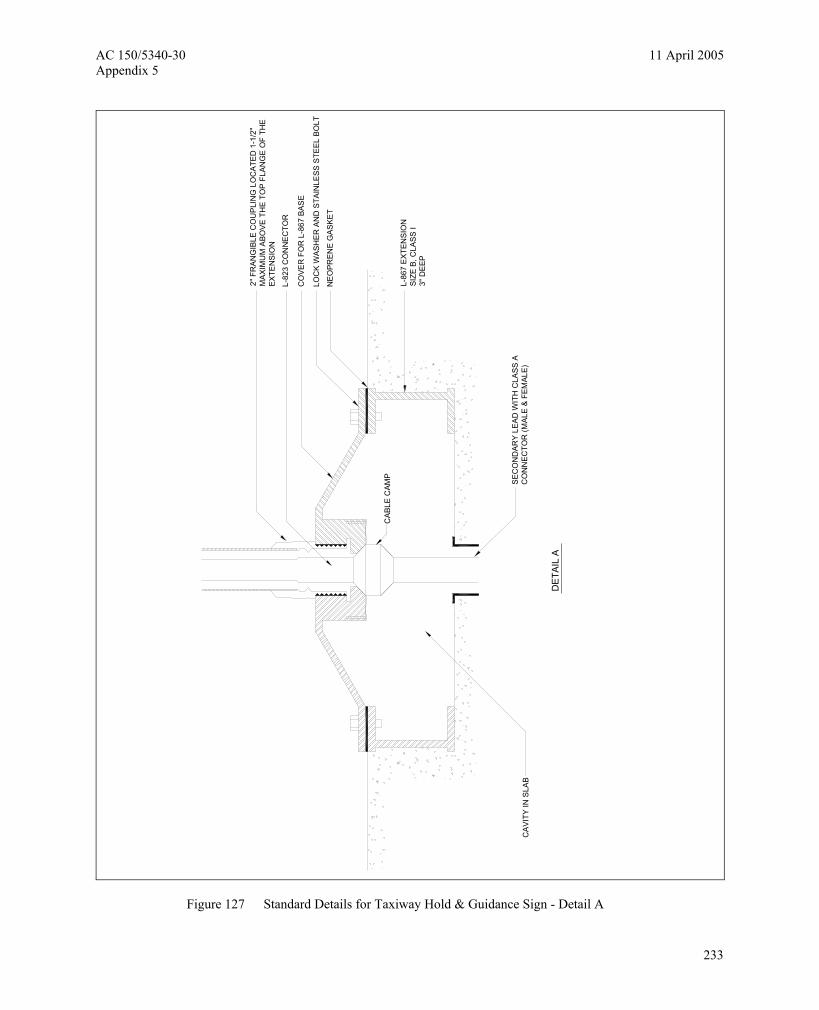
CAB
LE C
AMP
DE
TAIL
A
SEC
ON
DAR
Y LE
AD W
ITH
CLA
SS A
CO
NN
ECTO
R (M
ALE
& F
EMAL
E)C
AVI
TY IN
SLA
B
2" F
RAN
GIB
LE C
OU
PLI
NG
LO
CAT
ED
1-1
/2"
MAX
IMU
M A
BOVE
TH
E TO
P F
LAN
GE
OF
THE
EX
TEN
SIO
N
NE
OPR
ENE
GAS
KET
LOC
K W
ASH
ER A
ND
STA
INLE
SS S
TEEL
BO
LT
CO
VER
FO
R L
-867
BAS
E
L-82
3 C
ON
NE
CTO
R
L-86
7 E
XTEN
SIO
NSI
ZE B
, CLA
SS I
3" D
EEP
Figure 127 Standard Details for Taxiway Hold & Guidance Sign - Detail A
233
11 April 2005 AC 150/5340-30 Appendix 5
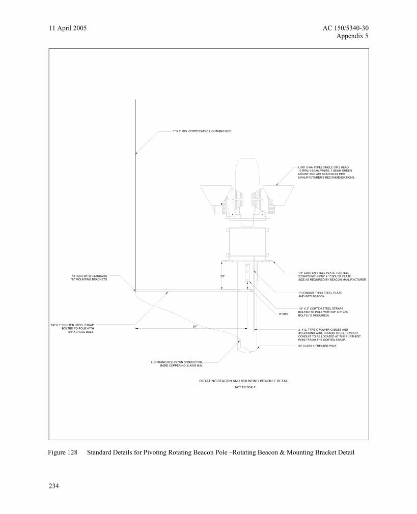
20"
8" MIN.
LIGHTNING ROD DOWN CONDUCTOR,BARE COPPER NO. 6 AWG MIN.
24"
NOT TO SCALE
ROTATING BEACON AND MOUNTING BRACKET DETAIL
ATTACH WITH STANDARD"U" MOUNTING BRACKETS
1/4" X 1" CORTEN STEEL STRAPBOLTED TO POLE WITH
5/8' X 3" LAG BOLT.
L-801 (FAA TYPE) SINGLE OR 2 HEAD12 RPM 1 BEAM WHITE, 1 BEAM GREENMOUNT AND AIM BEACON AS PERMANUFACTURER'S RECOMMENDATIONS.
1/4" CORTEN STEEL PLATE TO STEELSTRAPS WITH 5/16" X 1" BOLTS. PLATESIZE AS REQUIRED BY BEACON MANUFACTURER.
1" CONDUIT THRU STEEL PLATEAND INTO BEACON.
1/4" X 2" CORTEN STEEL STRAPSBOLTED TO POLE WITH 5/8" X 3" LAGBOLTS (12 REQUIRED)
2- #12, TYPE C POWER CABLES AND#8 GROUND WIRE IN RIGID STEEL CONDUIT.CONDUIT TO BE LOCATED AT THE FURTHESTPOINT FROM THE CORTEN STRAP.
50' CLASS 3 TREATED POLE
1" X 6' MIN. COPPERWELD LIGHTNING ROD
Figure 128 Standard Details for Pivoting Rotating Beacon Pole –Rotating Beacon & Mounting Bracket Detail
234

AC 150/5340-30 11 April 2005 Appendix 5
1/2" DIA. EYE BOLT THRU POLE WITH DOUBLE WASHERSAND NUTS. USED TO RAISE / LOWER POLE.CONTRACTOR TO PROVIDE 1/2' X 50' NYLON ROPEWITH STRAP SWIVEL ATTACHED TO ONE END.OTHER END TO BE NON RAVELING
DRILL HOLE THRU GALVANIZED THREADEDEND AND INSERT KEYED PADLOCK
1" RIGID STEEL CONDUIT
LOCKING DEVICE DETAILNOT TO SCALE
1/4" X 4" DIA. STEELGALV. PLATE WELDED
TO ANCHOR BOLT
1-1/4" ANCHOR BOLT WITH4" EYE ON ONE END AND
10" GALVANIZED THREADSON THE OTHER END
#6, BARE STRANDED COPPERDOWN CONDUCTOR
Figure 129 Standard Details for Pivoting Rotating Beacon Pole –Locking Device Detail
235
11 April 2005 AC 150/5340-30 Appendix 5
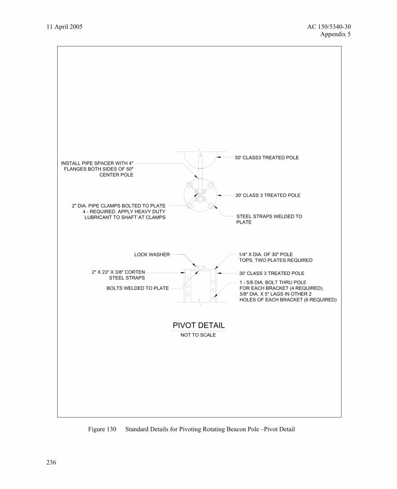
PIVOT DETAIL
BOLTS WELDED TO PLATE
2" X 23" X 3/8" CORTENSTEEL STRAPS
NOT TO SCALE
LOCK WASHER
2" DIA. PIPE CLAMPS BOLTED TO PLATE4 - REQUIRED. APPLY HEAVY DUTY LUBRICANT TO SHAFT AT CLAMPS
INSTALL PIPE SPACER WITH 4"FLANGES BOTH SIDES OF 50"
CENTER POLE
1 - 5/8 DIA. BOLT THRU POLEFOR EACH BRACKET (4 REQUIRED).5/8" DIA. X 5" LAGS IN OTHER 2HOLES OF EACH BRACKET (6 REQUIRED)
30' CLASS 3 TREATED POLE
1/4" X DIA. OF 30" POLE TOPS. TWO PLATES REQUIRED
STEEL STRAPS WELDED TO PLATE
30' CLASS 3 TREATED POLE
50' CLASS3 TREATED POLE
Figure 130 Standard Details for Pivoting Rotating Beacon Pole –Pivot Detail
236
AC 150/5340-30 11 April 2005 Appendix 5
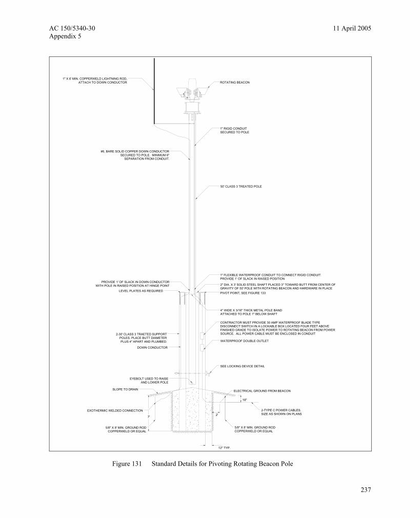
2-TYPE C POWER CABLES.SIZE AS SHOWN ON PLANS
CONTRACTOR MUST PROVIDE 30 AMP WATERPROOF BLADE TYPE DISCONNECT SWITCH IN A LOCKABLE BOX LOCATED FOUR FEET ABOVE FINISHED GRADE TO ISOLATE POWER TO ROTATING BEACON FROM POWER SOURCE. ALL POWER CABLE MUST BE ENCLOSED IN CONDUIT
2" DIA. X 3' SOLID STEEL SHAFT PLACED 3" TOWARD BUTT FROM CENTER OF GRAVITY OF 50' POLE WITH ROTATING BEACON AND HARDWARE IN PLACE
1" FLEXIBLE WATERPROOF CONDUIT TO CONNECT RIGID CONDUIT.PROVIDE 1' OF SLACK IN RAISED POSITION
EYEBOLT USED TO RAISEAND LOWER POLE
DOWN CONDUCTOR
2-30' CLASS 3 TRAETED SUPPORTPOLES. PLACE BUTT DIAMETERPLUS 4" APART AND PLUMBED.
LEVEL PLATES AS REQUIRED
PROVIDE 1' OF SLACK IN DOWN CONDUCTORWITH POLE IN RAISED POSITION AT HINGE POINT
SLOPE TO DRAIN
EXOTHERMIC WELDED CONNECTION
5/8" X 8' MIN. GROUND RODCOPPERWELD OR EQUAL
7'
12" TYP.
5/8" X 8' MIN. GROUND RODCOPPERWELD OR EQUAL
ELECTRICAL GROUND FROM BEACON
18"
SEE LOCKING DEVICE DETAIL
WATERPROOF DOUBLE OUTLET
4" WIDE X 3/16" THICK METAL POLE BANDATTACHED TO POLE 1" BELOW SHAFT
PIVOT POINT, SEE FIGURE 133
#6, BARE SOLID COPPER DOWN CONDUCTORSECURED TO POLE. MINIMUM 6"
SEPARATION FROM CONDUIT.
1" X 6' MIN. COPPERWELD LIGHTNING ROD,ATTACH TO DOWN CONDUCTOR
50' CLASS 3 TREATED POLE
1" RIGID CONDUITSECURED TO POLE
ROTATING BEACON
2'
Figure 131 Standard Details for Pivoting Rotating Beacon Pole
237

11 April 2005 AC 150/5340-30 Appendix 5
NOT TO SCALE
FOUNDATION DETAILWIND CONE
7'-0
" MIN
.
4 - 1/2" DIA. REINFORCING BARSWITH 3" COVER EQUALLY SPACED
IN FOUNDATION CONCRETE.3"
FINISHED GRADE
ANCHOR BOLTS
1-1/
4"
16" MIN.
18"
GROUND ROD 5/8" x 8'
2' CONDUIT
GROUNDING BUSHING
3"
2-1/
2"
TYPE C POWER CABLES1'-6
"1'
-6"
TYPE C POWER CABLES
GROUND ROD
#6 BARE
CYLINDRICAL FOUNDATION
NUMBER, SIZE, AND LOCATIONOF ANCHOR BOLTS PER MANUFACTURER
GROUNDING BUSHING - CONNECT TOGROUNDING LUG IN STEEL BASE
Figure 132 Standard Details for Wind Cone Foundation (L-807)
238

AC 150/5340-30 11 April 2005 Appendix 5
12' WIND CONE
3'-0"16
'-0"
FINISHED GRADE
NOT TO SCALE
1'-6
"
SEALED BEARING
4'-6
"
3'-0
"
POLE AND HINGE ARRANGEMENTPER MANUFACTURER SPECIFICATION.CONTRACTOR MUST PROVIDE 30 AMPWEATHERPROOF BLADE TYPE DISCONNECT SWITCHIN A LOCKABLE BOX LOCATED FOUR FEETABOVE FINISH GRADE TO ISOLATEPOWER TO WIND CONE LIGHTS FROMPOWER SOURCE. INSTALL WEATHERPROOF OUTLETON POWER SIDE OF BLADE SWITCHALL POWER CABLE MUST BE ENCLOSED RIGID STEEL CONDUIT.
CONCRETE FOUNDATION(SEE FIGURE 135)
FABRIC WIND CONE12'-0" LONG
TUBULAR ALUMINUM WIND-CONE SUPPORT4'-4" LONG
SHIELDED FACE FLOODLIGHTS (4-200 WATT)SPACED 90° APART
3/4" ALUMINUM CONDUIT EXTENSION
L-810 OBSTRUCTION LIGHT
Figure 133 Standard Details for Wind Cone –12’ Wind Cone
239

11 April 2005 AC 150/5340-30 Appendix 5
2' STEEL CONDUIT(TYP.)
CONCRETEFOOTING
NOT TO SCALEPLAN VIEW
L-880LIGHTUNIT
BASEL-867
CONCRETEENVELOPE
WOOD FRAMEOF TREATED2 X 4'S
4" MIN.(TYP.)
INSULATED BUSHING (TYP.)
24"
24"
24"
24"
6" (TYP.)
Figure 134 Standard Details for Precision Approach Path Indicators (PAPIs) –Plan View
240
AC 150/5340-30 11 April 2005 Appendix 5
L-86
7 B
ASE
(TY
P.)
LIG
HT
UN
IT L
OC
ATI
ON
S
PO
WE
R A
DA
PTE
R U
NIT
D
UN
IT 4
C
BB
PA
PI
UN
IT 3
C
A
UN
IT 2
A
C
A
UN
IT 1
B
RUNWAY CL
L-88
0 LA
MP
HO
US
ING
(TY
P.)
THR
ES
HO
LD
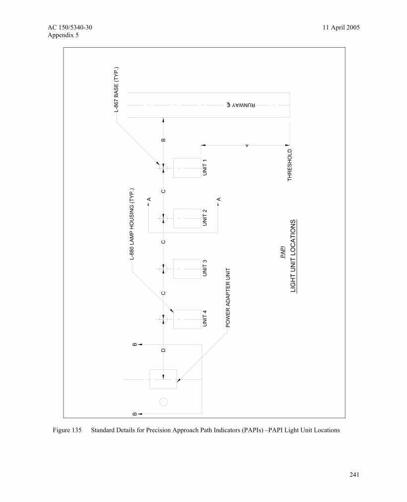
Figure 135 Standard Details for Precision Approach Path Indicators (PAPIs) –PAPI Light Unit Locations
241

11 April 2005 AC 150/5340-30 Appendix 5
TYPE
AN
D S
IZE
MA
NU
FAC
TUR
ER
WIR
E M
ESH
6" X
6" N
O.6
FRA
NG
IBLE
CO
UPL
ING
(TYP
.)
POW
ER
AD
APTE
RM
AY B
E IN
STAL
LH
OR
IZO
NTA
LLY
L-82
4,TY
PE
C #
8,6
00V
2" E
LBO
W
#6 B
ARE
3" T
YP.
18"
2'M
IN.
1' MIN.
2'M
IN. 8"
INS
ULA
TED
GR
OU
ND
ING
BU
SH
ING
(TY
P.)
L-82
4 TY
PE
C 6
00V
CAB
LES
TOL-
867
HO
USI
NG
, NU
MB
ER &
SIZ
EP
ER M
ANU
FAC
TUR
ER
EXO
THE
RM
IC W
ELD
CO
NN
EC
TIO
N
10"
NU
MB
ER P
ER
MA
NU
FAC
TUR
ER
240V
OR
120
V P
OW
ER S
UPP
LY
Figure 136 Standard Details for Precision Approach Path Indicators (PAPIs)
242

AC 150/5340-30 11 April 2005 Appendix 5
SO
NO
TUB
E F
OR
MED
TO
OBT
AIN
SM
OO
TH S
IDE
S (T
YP.
)
3" C
OVE
R O
N A
LL R
EIN
F. R
OD
SB
OTT
OM
, TO
P &
SID
ES
STA
INLE
SS
STE
EL H
OO
K B
OLT
W/N
UTS
(TYP
.)EM
BE
DD
ED M
INIM
UM
OF
8" IN
CO
NC
RET
E
7 FT.
36" D
IA. M
INIM
UM
CO
NC
RE
TE F
OO
TIN
G
1 1/
2" M
AX.
FRA
NG
IBLE
CO
UP
LIN
G
(TY
P.)
4" T
YP.
NO
T TO
SC
ALE
SE
CTI
ON
A-A
SID
E V
IEW
WA
TER
TIG
HT
FLE
XIBL
E C
ON
DU
IT
SIZE
PE
R M
ANU
FAC
TUR
ER
SLO
PE
TO D
RAI
N
FRAN
GIB
LE C
OU
PLI
NG
& 4
P, 1
0 A
WG
,60
0V Q
UIC
K D
ISC
ON
NEC
T P
ER
MAN
UFA
CTU
RER
DO
NO
T TA
PE
L-86
7 B
ASE
WE
EP H
OLE
SAN
D B
EDD
ING
1/2"
JO
INT
MA
TER
IAL
NO
TES
:
1. P
RO
VID
E F
RA
NG
IBLE
MO
UN
TS F
OR
ALL
LE
GS
OF
LIG
HT
UN
ITS
A
ND
PO
WE
R A
DA
PTER
S.
2. N
UM
BER
AN
D C
ON
FIG
UR
ATIO
N O
F LE
GS
PER
MAN
UFA
CTU
RER
.
3. Q
UIC
K D
ISC
ON
NEC
TS A
RE
NO
T R
EQ
UIR
ED
IN C
ABLE
S
EN
TER
ING
/LE
AVI
NG
TH
E PO
WER
AD
APTE
R.
4. G
RO
UN
D E
AC
H L
AMP
HO
USI
NG
AN
D P
OW
ER A
DAP
TER
P
ER
MA
NU
FAC
TUR
ER.
NO
. 4 B
AR
S S
PAC
ED
AR
OU
ND
WIR
E M
ES
H, 6
" X 6
" NO
.6
24"
1/2"
WA
SH
ED S
TON
E
FIN
ISH
ED
GR
ADE
6 M
IL B
LAC
K P
OLY
ETH
YLE
NE
L-88
0 LA
MP
HO
US
ING
4"
3"
Figure 137 Standard Details for Precision Approach Path Indicators (PAPIs) - Section A-A
243
11 April 2005 AC 150/5340-30 Appendix 5
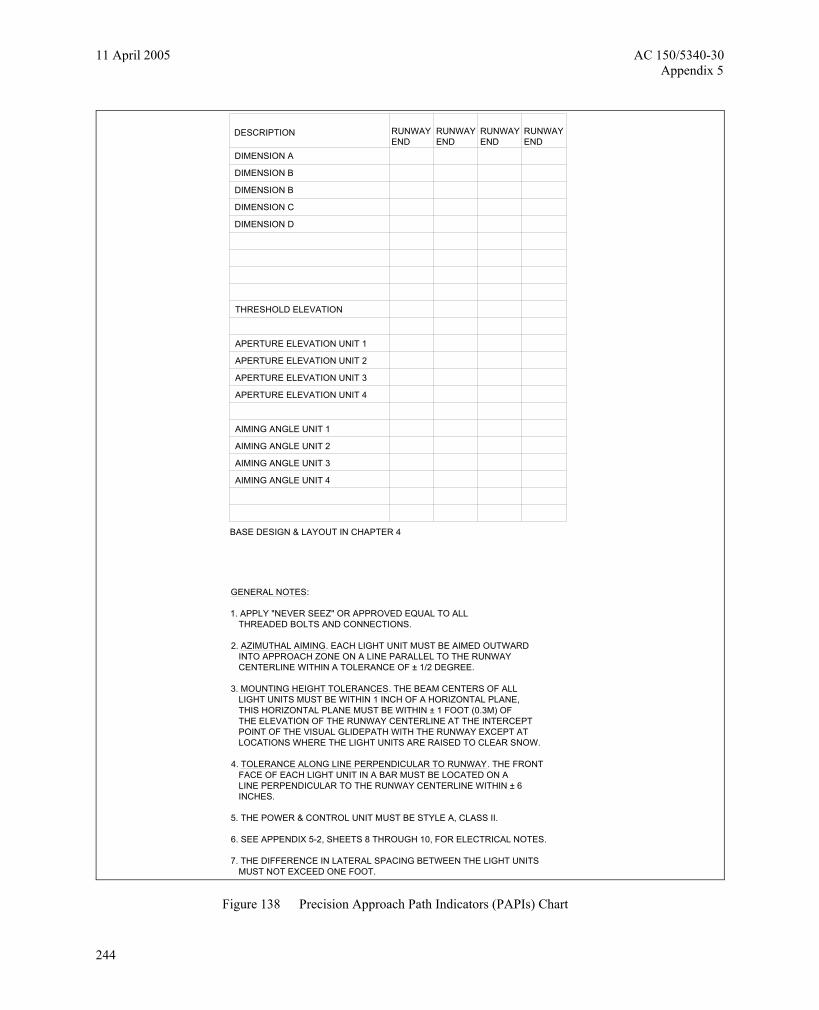
GENERAL NOTES:
1. APPLY "NEVER SEEZ" OR APPROVED EQUAL TO ALL THREADED BOLTS AND CONNECTIONS.
2. AZIMUTHAL AIMING. EACH LIGHT UNIT MUST BE AIMED OUTWARD INTO APPROACH ZONE ON A LINE PARALLEL TO THE RUNWAY CENTERLINE WITHIN A TOLERANCE OF ± 1/2 DEGREE.
3. MOUNTING HEIGHT TOLERANCES. THE BEAM CENTERS OF ALL LIGHT UNITS MUST BE WITHIN 1 INCH OF A HORIZONTAL PLANE, THIS HORIZONTAL PLANE MUST BE WITHIN ± 1 FOOT (0.3M) OF THE ELEVATION OF THE RUNWAY CENTERLINE AT THE INTERCEPT POINT OF THE VISUAL GLIDEPATH WITH THE RUNWAY EXCEPT AT LOCATIONS WHERE THE LIGHT UNITS ARE RAISED TO CLEAR SNOW.
4. TOLERANCE ALONG LINE PERPENDICULAR TO RUNWAY. THE FRONT FACE OF EACH LIGHT UNIT IN A BAR MUST BE LOCATED ON A LINE PERPENDICULAR TO THE RUNWAY CENTERLINE WITHIN ± 6 INCHES.
5. THE POWER & CONTROL UNIT MUST BE STYLE A, CLASS II.
6. SEE APPENDIX 5-2, SHEETS 8 THROUGH 10, FOR ELECTRICAL NOTES.
7. THE DIFFERENCE IN LATERAL SPACING BETWEEN THE LIGHT UNITS MUST NOT EXCEED ONE FOOT.
BASE DESIGN & LAYOUT IN CHAPTER 4
RUNWAYEND
DESCRIPTION
AIMING ANGLE UNIT 4
AIMING ANGLE UNIT 3
AIMING ANGLE UNIT 2
AIMING ANGLE UNIT 1
APERTURE ELEVATION UNIT 4
APERTURE ELEVATION UNIT 3
APERTURE ELEVATION UNIT 2
APERTURE ELEVATION UNIT 1
THRESHOLD ELEVATION
DIMENSION D
DIMENSION C
DIMENSION B
DIMENSION B
DIMENSION A
RUNWAYEND
RUNWAYEND
RUNWAYEND
Figure 138 Precision Approach Path Indicators (PAPIs) Chart
244
AC 150/5340-30 11 April 2005 Appendix 5
3/4"
DIA
. WEE
P H
OLE
2" R
IGID
GAL
V. S
TEEL
CO
ND
UIT
(NO
EXP
OSE
D W
IRES
)
PRO
FILE
VIE
W
FRA
NG
IBLE
CO
UPL
ING
(TYP
.)
4- 1
/2" D
IA. R
EIN
FOR
CIN
GB
ARS
CO
VER
ING
EQ
UAL
LY S
PAC
EDIN
FO
UN
DA
TIO
N C
ON
CR
ETE
SLO
PE
TO D
RAI
N
CO
NC
RE
TE F
OU
ND
ATI
ON
CA
ST S
PLIC
E
FRAN
GIB
LE C
OU
PLIN
G (T
YP.
)
SEE
NO
TE 1
L-84
9, S
TYLE
A O
PTIC
AL H
EAD
SEE
NO
TE 2
6" M
IN. S
AN
D B
AC
KFI
LL (T
YP.)
I/C, #
8.5K
V, L
-824
TYP
E C
CAB
LE
TRA
NSF
OR
MER
(IS
OLA
TIO
N, I
NTE
RFA
CE,
CO
NTR
OL)
AS
RE
QU
IRED
BY
TH
E R
EIL
MAN
UFA
CTU
RE
R
L-86
7 BA
SE S
IZE
D, 2
4" D
EEP
, CLA
SS I
CO
NC
RE
TE B
ACKF
ILL
4" (T
YP.)
FIN
ISH
ED G
RAD
E
SLO
PE T
O D
RAI
N A
WAY
FR
OM
L-8
67 B
ASE
STAI
NLE
SS
STE
EL
CO
VER
BO
LTS
L-86
7 S
OLI
D S
TEEL
CO
VER
PR
OVI
DE
3 F
EET
MIN
. OF
SLA
CK
IN E
ACH
PR
IMAR
Y C
ABLE
AN
D S
ECO
ND
AR
Y EX
TEN
SIO
N
CO
LOR
CO
DE
D T
APE
FO
R W
IRE
IDEN
TIFI
CAT
ION
LOC
ATE
D W
ITH
IN 6
" OF
L-82
3 C
ON
NEC
TOR
PLU
G IN
SID
E E
NTR
Y W
ITH
DU
CT
SEA
L (T
YP.)
SPE
CIA
L O
RD
ER L
EN
GTH
SEC
ON
DAR
Y E
XTEN
SIO
NW
ITH
CLA
SS A
CO
NN
ECTO
R (M
ALE
& FE
MAL
E)
SEE
NO
TE 4
MAS
TER
/SLA
VE
INTE
RFA
CE
SEE
NO
TE 4
L-82
3C
ON
NEC
TOR
7' MIN.
16"
GE
NE
RAL
NO
TES
1. N
UM
BER
OF
MO
UN
TS P
ER M
ANU
FAC
TUR
ER.
ON
E O
F TH
E LE
GS
MU
ST B
E U
SED
AS
WIR
EWA
Y.2.
OPT
ICA
L H
EAD
MAY
ALS
O B
E M
OU
NTE
D O
N F
RO
NT
OR
SID
E O
F TH
E PO
WER
& C
ON
TRO
L U
NIT
.3.
AD
JUS
TAB
LE C
UR
RE
NT
SEN
SIN
G O
N/O
FF C
ON
TRO
L C
IRC
UIT
MU
ST B
E PR
OV
IDE
D.
4. N
UM
BER
, SIZ
E A
ND
TY
PE O
F C
ON
DU
CTO
RS
BET
WEE
N T
HE
POW
ER S
UP
PLY/
CO
NTR
OL
TRA
NS
FOR
MER
S,
AND
TH
E M
AST
ER P
OW
ER
AN
D C
ON
TRO
L U
NIT
MU
ST B
E PE
R M
ANU
FAC
TUR
ER.
SAM
E M
US
T AP
PLY
TO
W
IRIN
G
BET
WEE
N T
HE
MA
STE
R A
ND
TH
E S
LAV
E U
NIT
S, E
XCE
PT T
HA
T TH
E C
ABL
E M
US
T BE
L-8
24, T
YPE
C.
5. C
OLO
R C
OD
ED W
IRE
IDEN
TIFI
CAT
ION
TAP
E AS
FO
LLO
WS:
WH
EN F
ACIN
G L
IGH
T W
ITH
BAC
K TO
P
AVEM
ENT,
C
ABLE
TO
LEF
T IS
CO
DED
RE
D A
ND
CA
BLE
TO T
HE
RIG
HT
IS C
OD
ED B
LUE.
6. S
EE A
PPE
ND
IX 5
-2, S
HE
ETS
8 T
HR
OU
GH
10,
FO
R E
LEC
TRIC
AL N
OTE
S.
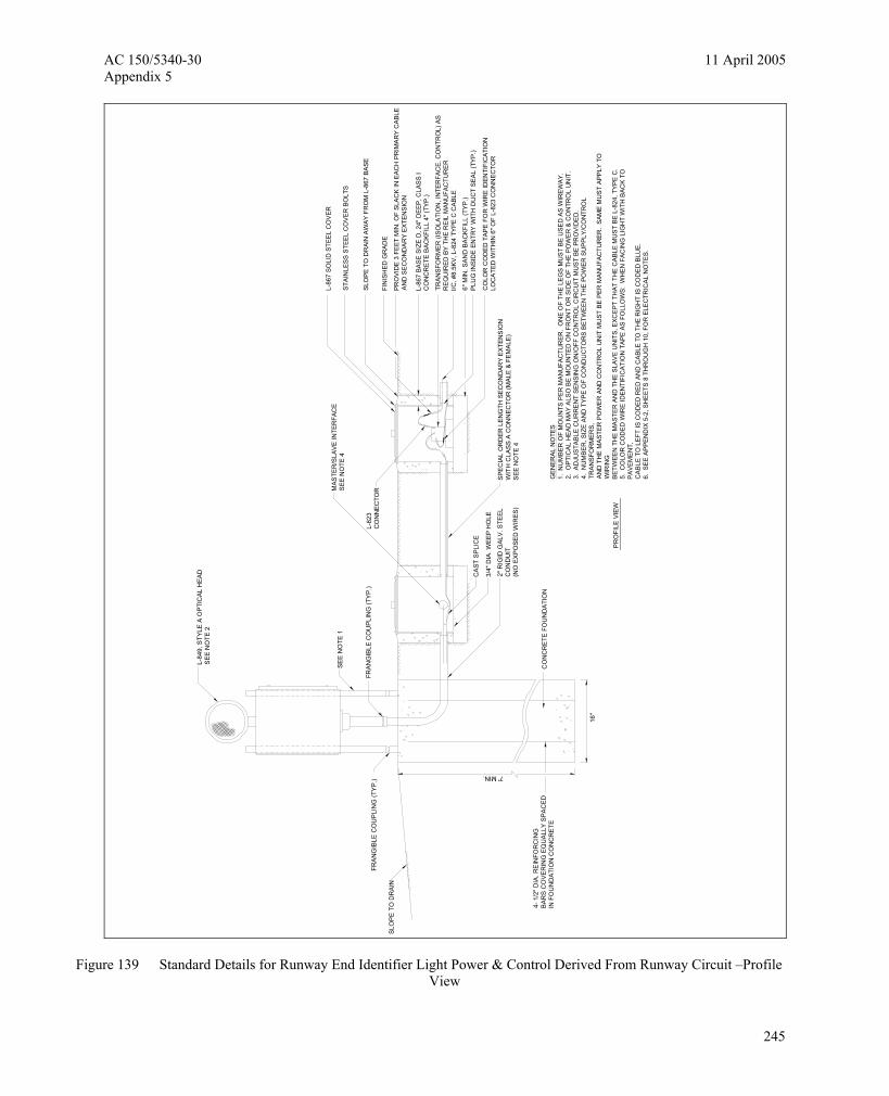
Figure 139 Standard Details for Runway End Identifier Light Power & Control Derived From Runway Circuit –Profile View
245
11 April 2005 AC 150/5340-30 Appendix 5
TRANSFORMERSMASTER/SLAVE INTERFACE
CONNECTED TO EDGELIGHTING CIRCUIT
PLAN VIEW
L-867 BASE
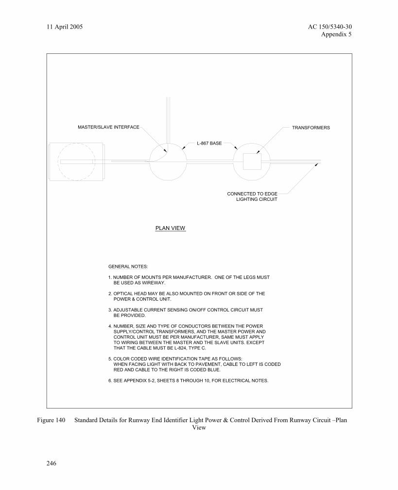
GENERAL NOTES:
1. NUMBER OF MOUNTS PER MANUFACTURER. ONE OF THE LEGS MUST BE USED AS WIREWAY.
2. OPTICAL HEAD MAY BE ALSO MOUNTED ON FRONT OR SIDE OF THE POWER & CONTROL UNIT.
3. ADJUSTABLE CURRENT SENSING ON/OFF CONTROL CIRCUIT MUST BE PROVIDED.
4. NUMBER, SIZE AND TYPE OF CONDUCTORS BETWEEN THE POWER SUPPLY/CONTROL TRANSFORMERS, AND THE MASTER POWER AND CONTROL UNIT MUST BE PER MANUFACTURER, SAME MUST APPLY TO WIRING BETWEEN THE MASTER AND THE SLAVE UNITS. EXCEPT THAT THE CABLE MUST BE L-824, TYPE C.
5. COLOR CODED WIRE IDENTIFICATION TAPE AS FOLLOWS: WHEN FACING LIGHT WITH BACK TO PAVEMENT, CABLE TO LEFT IS CODED RED AND CABLE TO THE RIGHT IS CODED BLUE.
6. SEE APPENDIX 5-2, SHEETS 8 THROUGH 10, FOR ELECTRICAL NOTES.
Figure 140 Standard Details for Runway End Identifier Light Power & Control Derived From Runway Circuit –Plan View
246
AC 150/5340-30 11 April 2005 Appendix 5
A5-1. Electrical Notes
a. General
(1) The electrical installation, as a minimum, must meet the NEC and local regulations.
(2) The contractor must ascertain that all lighting system components furnished by him (included FAA approved equipment) are compatible in all respects with each other and the remainder of the new/existing system. Any non-compatible components furnished by this contractor must be replaced by the contractor at no additional cost to the airport sponsor with a similar unit, approved by the engineer (different model or different manufacturer), that is compatible with the remainder of the airport lighting system.
(3) In case the contractor selects to furnish and install airport lighting equipment requiring additional wiring, transformers, adapters, mountings, etc., to those shown on the drawings and/or listed in the specifications, any cost for these items must be incidental to the equipment cost.
(4) The contractor-installed equipment (including FAA approved) must not generate any electromagnetic interference in the existing and/or new communications, weather, air navigation, and air traffic control equipment. Any equipment generating such interference must be replaced by the contractor at no additional cost with equipment meeting the applicable specifications and not generating any interference.
(5) When a specific type, style, class, etc., of FAA approved equipment is specified only that type, style, class, etc., will be acceptable, even though equipment of other types, style, class, etc., may be FAA approved.
(6) Any and all instructions from the engineer to the contractor regarding changes in, or deviations from, the plans and specifications must be in writing with copies sent to the airport sponsor and the FAA field office (ADO/AFO). The contractor must not accept any verbal instructions from the engineer regarding any changes from the plans and specifications.
(7) A minimum of three copies of instruction book must be supplied with each different type of equipment. The books describing a more sophisticated type of equipment, such as regulators, PAPI, REIL, etc., at a minimum must contain the following:
(a) A detailed description of the overall equipment and its individual components.
(b) Theory of operation including the function of each component.
(c) Installation instructions.
(d) Start-up instructions.
(e) Preventative maintenance requirements.
(f) Chart for troubleshooting.
(g) Complete power and control detailed wiring diagram(s), showing each conductor/connection/component "black" boxes are not acceptable. The diagram or the narrative must show voltages/currents/wave shapes at strategic locations to be used when
247

11 April 2005 AC 150/5340-30 Appendix 5
checking and/or troubleshooting the equipment. When the equipment has several brightness steps, these parameters must be indicated for all the different modes.
(h) Parts list will include all major and minor components, such as resistors, diodes, etc. It must include a complete nomenclature of each component and, if applicable, the name of its manufacturer and the catalog number.
(i) Safety instructions.
b. Power and control
(1) Stencil all electrical equipment to identify function, circuit voltage and phase. Where the equipment contains fuses, also stencil the fuse or fuse link ampere rating. Where the equipment does not have sufficient stenciling area, the stenciling must be done on the wall next to the unit. The letters must be one inch high and painted in white or black paint to provide the highest contrast with the background.
(2) Color code all phase wiring by the use of colored wire insulation and/or colored tape. Where tape is used, the wire insulation must be black. Black and red must be used for single-phase, three wire systems and black, red and blue must be used for three-phase systems. Neutral conductors, size no. 6 AWG or smaller, must be identified by a continuous white or natural conductors larger than no. 6 AWG must be identified either by a continuous white or natural gray outer finish along its entire length or by the use of white tape at its terminations and inside accessible wireways.
(3) All branch circuit conductors connected to a particular phase must be identified with the same color. The color coding must extended to the point of utilization.
(4) In control wiring the same color must be used throughout the system for the same function, such as 10%, 30%, 100% brightness control, etc.
(5) All power and control circuit conductors must be copper; aluminum must not be accepted. This includes wire, cable, busses, terminals, switch/panel components, etc.
(6) Low voltage (600 v.) and high voltage (5000 v.) conductors must be installed in separate wireways.
(7) Neatly lace wiring in distribution panels, wireways, switches and pull/junction boxes.
(8) The minimum size of pull/junction boxes, regardless of the quantity and the size of the conductors shown, must be as follows:
(a) In straight pulls the length of the box must not be less than eight times the trade diameter of the larger conduit. The total area (including the conduit cross-sectional area) of a box end must be at least 3 times greater than the total trade cross-sectional area of the conduits terminating at the end.
(b) In angle or u-pulls the distance between each conduit entry inside the box and the opposite wall of the box must not be less than six times the trade diameter of the largest conduit. This distance must be increased for additional entries by the amount of the sum of the diameters of all other conduit entries on the same wall of the box. The distance between conduit entries enclosing the same conductor must of not be less than six times the trade diameter of the largest conduit.
248
AC 150/5340-30 11 April 2005 Appendix 5
(9) A run of conduit between terminations at equipment enclosures, square ducts and pull/junction boxes, must not contain more than the equivalent of four quarter bends (360 degrees total), including those bends located immediately at the terminations. Cast, conduit type outlets must not be treated as pull/junction boxes.
(10) Equipment cabinets must not be used as pull/junction boxes. Only wiring terminating at the equipment must be brought into these enclosures.
(11) Splices and junction points must be permitted only in junction boxes, ducts equipped with removable covers, and at easily accessible locations.
(12) Circuit breakers in power distribution panel(s) must be thermal-magnetic, molded case, permanent trip with 100-ampere, minimum, frame.
(13) Dual lugs must be used where two wires, size no. 6 or larger, are to be connected to the same terminal.
(14) All wall mounted equipment enclosures must be mounted on wooden mounting boards.
(15) Wooden equipment mounting boards must be plywood, exterior type, 3/4 inch minimum thickness, both sides painted with one coat of primer and two coats of gray, oil-based paint.
(16) Rigid steel conduit must be used throughout the installation unless otherwise specified. The minimum trade size must be 3/4 inch.
(17) All rigid conduit must be terminated at constant current regulators with a section (10" minimum) of flexible conduit.
(18) Unless otherwise shown all exposed conduits must be run parallel to, or at right angles with, the lines of the structure.
(19) All steel conduits, fittings, nuts, bolts, etc., must be galvanized.
(20) Use conduit bushings at each conduit termination. Where no. 4 AWG or larger ungrounded wire is installed, use insulated bushings.
(21) Use double lock nuts at each conduit termination.
(22) Wrap all primary and secondary power transformer connections with sufficient layers of insulating tape and cover with insulating varnish for full value of cable insulation voltage.
(23) Unless otherwise noted, all indoor single conductor control wiring must be no. 12 AWG.
(24) Both ends of each control conductor must be terminated at a terminal block. The terminal block must be of proper rating and size for the function intended and they must be located in equipment enclosures or special terminal cabinets.
(25) All control conductor terminators must be of the open-eye connector/screw type. Soldered, closed-eyed terminators, or terminators without connectors are not acceptable.
(26) In terminal block cabinets the minimum spacing between parallel terminal blocks must be 6 inches. The minimum spacing between terminal block sides/ends and cabinet sides/bottom/top must be 5
249

11 April 2005 AC 150/5340-30 Appendix 5
inches. The minimum spacing will be increased as required by the number of conductors. Additional spacing must be provided at conductor entrances.
(27) Both ends of all control conductors must be identified as to the circuit, terminal, block, and terminal number. Only stick-on labels must be used.
(28) A separate and continuous neutral conductor must be installed and connected for each breaker circuit in the power panel(s) from the neutral bar to each power/control circuit.
(29) The following must apply to relay/contactor panel/enclosures:
(a) All components must be mounted in dust proof enclosures with vertically hinged covers.
(b) The enclosures must have ample space for the circuit components, terminal blocks, and incoming internal wiring.
(c) All incoming/outgoing wiring must be terminated at terminal blocks.
(d) Each terminal on terminal blocks and on circuit components must be clearly identified.
(e) All control conductor terminations must be of the open-eye connector/screw type. Soldered, closed-eye connectors, or terminations without connectors are not acceptable.
(f) When the enclosure cover is opened, all circuit components, wiring, and terminals must be exposed and accessible without any removal of any panels, covers, etc., except those covering high voltage components.
(g) Access to, or removal of, a circuit component or terminal block will not require the removal of any other circuit component or terminal block.
(h) Each circuit component must be clearly identified indicating its corresponding number shown on the drawing and its function.
(i) A complete wiring diagram (not a schematic diagram) must be mounted on the inside of the cover. The diagram must represent each conductor by a separate line.
(j) The diagram must identify each circuit component and numbering and color of each internal conductor and terminal.
(k) All wiring must be neatly trained and laced.
(l) Minimum wire size must be no. 12 AWG.
c. Field lighting
(1) Unless otherwise notified all underground field power multiple and series circuit conductors whether direct earth burial (DEB) or in duct/conduit must be FAA approved L-824 type. Insulation voltage and size must be as specified.
(2) No components of primary circuit such as cable, connectors and transformers must be brought above ground at edge lights, signs, REIL, etc.
250

AC 150/5340-30 11 April 2005 Appendix 5
(3) There must be no exposed power/control cables between the point where they leave the underground (DEB or L-867 bases) and where they enter the equipment (such as taxiway signs, PAPI, REIL, etc.). Enclosures. These cables must be enclosed in rigid conduit or in flexible water-tight conduit with frangible coupling(s) at the grade or the housing cover, as shown in applicable details.
(4) The joints of the L-823 primary connectors must be wrapped with one layer of rubber or synthetic rubber tape and one layer of plastic tape, one half lapped, extending at least 1-1/2 inches on each side of the joint, as shown in Figure 122.
(5) The cable entrance into the field attached L-823 connectors must be enclosed by a heat-shrinkable tubing with continuous internal adhesive as shown in Figure 122.
(6) The ID of the primary L-823 field attached connectors must match the cable ID to provide a watertight cable entrance. This entrance must be encapsulated in a heat shrinkable tubing with continuous factory applied internal adhesive, as shown in Figure 122.
(7) L-823 type 11, two-conductor secondary connector must be class "A" (factory molded).
(8) There must be no splices in the secondary cable(s) within the stems of a runway/taxiway edge/threshold lighting fixtures and the wireways leading to taxiway signs and PAPI/REIL equipment.
(9) Electrical insulating grease must be applied within the L-823, secondary, two conductor connectors to prevent water entrance. These connectors must not be taped.
(10) Deb isolation transformers must be buried at a depth of 10 inches on a line crossing the light and perpendicular to the runway/taxiway centerline at a location 12 inches from the light opposite from the runway/taxiway.
(11) Deb primary connectors must be buried at a depth of 10 inches near the isolation transformer. They must be orientated parallel with the runway/taxiway centerline. There must be no bends in the primary cable 6 inches, minimum, from the entrance into the field-attached primary connection.
(12) A slack of 3 feet, minimum, must be provided in the primary cable at each transformer/connector termination. At stake-mounted lights the slack must be loosely coiled immediately below the isolation transformer.
(13) Direction of primary cables must be identified by color coding as follows, when facing light with back facing pavement, cable to the left is coded red and cable to the right is coded blue, this applies to the stake-mounted lights and base-mounted lights where the base has only one entrance.
(14) L-867 bases must be size b, 24" deep class 1 unless otherwise noted.
(15) Base-mounted frangible couplings must not have weep holes to the outside. Plugged up holes must not be acceptable. It must have a 1/4" diameter minimum or equivalent opening for drainage from the space around the secondary connector into the L-867 base.
(16) The elevation of the frangible coupling groove must not exceed 1-1/2" above the edge of the cover in case of base-mounted couplings, or the top of the stake in case of stake-mounted couplings.
251

11 April 2005 AC 150/5340-30 Appendix 5
(17) Where the frangible coupling is not an integral part of the light fixture stem or mounting leg, a bead
of silicon seal must be applied completely around the light stem or wireway at frangible coupling to provide a watertight seal.
(18) Tops of the stakes supporting light fixtures must be flush with the surrounding grade.
(19) Plastic lighting fixture components, such as lamp heads, stems, frangible couplings, base covers, brackets, stakes, must not be acceptable. L-867 plastic transformer housings are acceptable. The metal threaded fitting must be set in flange during casting process. Base cover bolts must be fabricated from 18-8 stainless steel.
(20) The tolerance for the height of runway/taxiway edge lights must be ± one (1) inch. In case of stake-mounted lights, the specified lighting fixture height must be measured between the top of the stake and the top of the lens. In case of base-mounted lights. The specified lighting fixture height must be measured between the top of the base flange and the top of the lens, thus including the base cover. The frangible coupling, the stem, the lamp housing and the lens.
(21) The tolerance for the lateral spacing (light lane to runway/taxiway centerline) of runway/taxiway edge lights must be ± one (1) inch. This also applies at intersections to lateral spacing between lights of a runway/taxiway and the intersecting runway/taxiway.
(22) Soil permitting the L-867 bases must not be pre-cast in concrete. Concrete around the bases must be used as a backfill.
(23) Entrances into L-867 bases must be plugged from the inside with duct seal.
(24) Galvanized/painted equipment/component surfaces must not be damaged by drilling, filing, etc. Drain holes in metal transformer housings must be made before galvanized.
(25) Edge light numbering tags must be facing the pavement.
(26) Cable/splice/duct markers must be pre-cast concrete of the size shown. Letters/numbers/arrows for the legend to be impressed into the tops of the markers must be pre-assembled and secured in the mold before the concrete is poured. Legend inscribed by hand in wet concrete must not be acceptable.
(27) All underground cable runs must be identified by cable markers at 200 feet maximum spacing, with an additional marker at each change of direction of the cable run. Cable markers must be installed immediately above the cable.
(28) Locations of all DEB underground cable splice/connections, except those at isolation transformers, must be identified by splice markers. Splice markers must be placed immediately above the splice/connections.
(29) The cable and splice markers must identify the circuits which the cables belong to, such as RWY 4-22, PAPI-4, PAPI-22, etc.
(30) Locations of ends of all underground ducts must be identified by duct markers.
(31) The preferred mounting method of runway and taxiway signs is by the use of single row of legs. However, two rows will be acceptable.
252

AC 150/5340-30 11 April 2005 Appendix 5
(32) The preferred method to bring the power cable into an L-858 sign is method A, as shown in Figure 126, however, method B is also acceptable.
(33) Stencil horizontal and vertical aiming angles on each REIL flash head or equipment enclosure. The numerals must be black and one inch minimum height.
(34) Stencil vertical aiming angles on the outside of each PAPI lamp housing. The numerals must be black and one inch minimum height.
(35) All power and control cables in man/hand holes must be tagged. Use embossed copper strips attached at both ends to the cable by the use of plastic straps. Minimum of two tags must be provided on each cable in a man/hand hole - one at the cable entrance and one at the cable exit.
(36) Apply an oxide inhibiting, anti-seizing compound to all screws, nuts and frangible coupling threads.
(37) There must be no splices between the isolation transformers. L-823 connectors are allowed at transformer connections only, unless otherwise shown.
(38) Deb splices in home runs must be of the cast type, unless otherwise shown.
(39) Where a parallel, constant voltage PAPI system is provided, the "T" splices must be of the cast type.
(40) Concrete used for slabs, footing, backfill around transformer housings, markers, etc., must be 3000 PSI, min., air-entrained.
d. Grounding
(1) Ground all non-current-carrying metal parts of electrical equipment by using no. 6 AWG bare copper wire to be run inside cabinets and in conduits together with other wires. Where this is not feasible, run the exposed grounding wire parallel or at right angles to the building line and secure it at least every 24 inches and within 6 inches from bend or junction. The exposed wire may be no. 6 AWG if it is not subjected to physical abuse, otherwise no. 4 AWG must be used.
(2) All ground connections to ground rods, busses, panels, etc., must be made with pressure type solderless lugs and ground clamps. Soldered or bolt and washer type connections are not acceptable. Clean all metal surfaces before making ground connections.
(3) Tops of ground rods must be 10 inches below grade.
(4) The resistance to ground of the vault grounding system with the commercial power line neutral disconnected must not exceed 10 ohms.
(5) The resistance to ground of the counterpoise system, or at isolation locations, such as airport beacon must not exceed 25 ohms.
253

11 April 2005 AC 150/5340-30 Appendix 5
Intentionally left blank.
254