978-1-58503-427-7 -- civil 3d 2008 introduction - sdc publications
TRANSCRIPT

AutoCAD Civil 3D 2008
Introduction to Corridor Design Project Workbook
SDC
Schroff Development Corporation
www.schroff.com www.schroff-europe.com
PUBLICATIONS

Copyrighted Material
Copyrighted
Material
Copyrighted Material
Copyrighted
Material
5 - 1
Exercise 5:
Build and Edit Surfaces
Start a New Drawing
Import a Coordinate Point File
Update Point Groups
Create a New Surface
Add Point Groups
Create a Boundary
Create a Breakline
Editing Surfaces
Point Display
Surface Display
Add Contour Labels
Contour Label Style
Point Table
Object Viewer

Copyrighted Material
Copyrighted
Material
Copyrighted Material
Copyrighted
Material
Civil 3D 2008 Introduction to Corridor Design
5 - 2
Start a New Drawing
1. Close any open drawings.
2. Select File>New. In the Select Template dialog box, highlight the _0-C3D 2008 CLASS.dwt template you just created.
3. Click Open.
4. Select File>Save As.
5. Browse to C:\Civil 3D 2008 Intro to Corridor Design Exercise Files\Mackinaw Estates.
6. Save this drawing as Mackinaw Estates Site Plan 08.dwg.

Copyrighted Material
Copyrighted
Material
Copyrighted Material
Copyrighted
Material
Build and Edit Surfaces
5 - 3
Import a Coordinate Point File
The Mackinaw Estates project includes creating a road and lots on a 30 acre site. A survey team collected the existing conditions and you have been provided with a comma delimited ASCII coordinate file in a Point number, Northing, Easting, Elevation, Description format.
The first task is to create an existing conditions base map for this site.
1. Select Points>Create Points. Click (Import Points).
2. Set the Format as PNEZD (comma delimited).
3. Browse to C:\Civil 3D 2008 Intro to Corridor Design Exercise Files\Data directory and select ME Site Survey2008.txt. You might have to change the File Type to (.TXT).
4. Click Open.

Copyrighted Material
Copyrighted
Material
Copyrighted Material
Copyrighted
Material
Civil 3D 2008 Introduction to Corridor Design
5 - 4
5. Clear the options under the Advanced options area.
6. Click OK.
7. Zoom Extents.
The points are imported and the Description Keys provide symbols as required.

Copyrighted Material
Copyrighted
Material
Copyrighted Material
Copyrighted
Material
Build and Edit Surfaces
5 - 5
Note the existing dirt road. You would normally create breaklines along the road, but in this case, they are not required. There is also a stream running south to north on the site. The stream requires a breakline for the surface to generate properly.
Since the original ground survey there has been a change. A groundwater well has been drilled and installed. The surveyors returned to the site and gathered the information needed to locate the well. They set up from an existing control point and recorded the bearing, distance, and elevation for the well.
8. In the Prospector tab, select once on Points to highlight it.
9. In the Item View, right-click on point number 13 and select Zoom to. This was the point used to locate the well.

Copyrighted Material
Copyrighted
Material
Copyrighted Material
Copyrighted
Material
Civil 3D 2008 Introduction to Corridor Design
5 - 6
10. Use Zoom Center and a height of 300 to see the well point. You can also use the wheel on your mouse to zoom out. Your screen should look similar to the one displayed below.
11. Click on the Intersection drop-down menu and select Direction/Distance.
The figure below, taken from AutoCAD Civil 3D Help, explains the command prompts. It uses two points, one for the radial point and one for the direction point. You will use the same point for both.

Copyrighted Material
Copyrighted
Material
Copyrighted Material
Copyrighted
Material
Build and Edit Surfaces
5 - 7
12. Follow the command prompts:
>>Please specify a location for the radial point: pick _node of CTRL point# 13
>>Enter radius <0.0000>: 198.30
>>Specify start point: pick _node of CTRL point# 13
>>Specify direction at start point or [Bearing/aZimuth]: B
>>Quadrants - NE = 1, SE = 2, SW = 3, NW = 4
>>Specify quadrant (1-4) or [aZimuth/Angle]: enter a number or pick in a quadrant – 4 - NW
>>Specify bearing or [aZimuth/Angle]: 55.1106
>>Specify an offset <0.0000>: 0
>>Enter a point description <.>: WELL
>>Specify a point elevation <.>: 295.05
>>Please specify a location for the radial point: <Esc>
13. Close the Create Points toolbar. Your screen should look similar to that shown below.

Copyrighted Material
Copyrighted
Material
Copyrighted Material
Copyrighted
Material
Civil 3D 2008 Introduction to Corridor Design
5 - 8
Update Point Groups
You will use Point Groups EG TOPO and VEGETATION as part of the data for this surface. Therefore, the Point Groups must be updated to include the points permitted by their filters.
1. In the Prospector tab, select Point Groups to see its collection in the Item View or expand Point Groups to see its collection directly in the Tree View.
The symbol in front of each Point Group indicates that the Point Group is out of date. The Point Group _All Points has no symbol, because it automatically contains all of the points in the drawing regardless of any filters.

Copyrighted Material
Copyrighted
Material
Copyrighted Material
Copyrighted
Material
Build and Edit Surfaces
5 - 9
2. Right-click on Point Groups and select Update. The Point Groups are now current.
3. Zoom Extents.
Copyrighted Material
Copyrighted
Material
Copyrighted Material
Copyrighted
Material
Civil 3D 2008 Introduction to Corridor Design
5 - 10
Create a New Surface
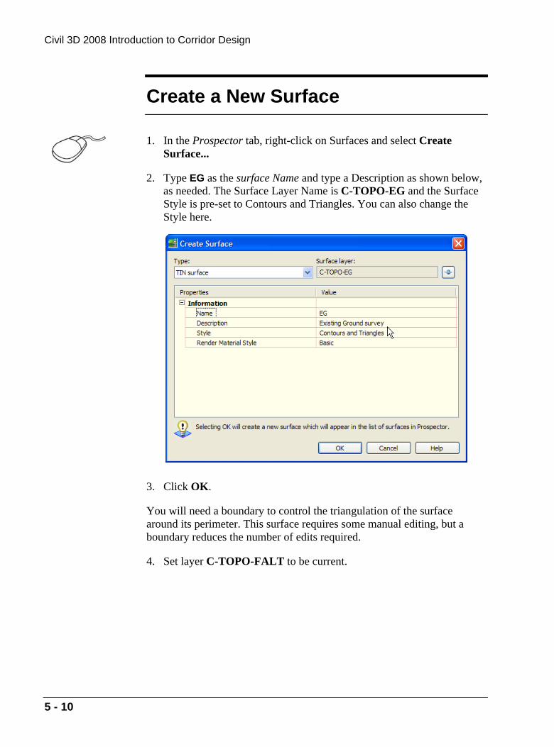
1. In the Prospector tab, right-click on Surfaces and select Create Surface...
2. Type EG as the surface Name and type a Description as shown below, as needed. The Surface Layer Name is C-TOPO-EG and the Surface Style is pre-set to Contours and Triangles. You can also change the Style here.
3. Click OK.
You will need a boundary to control the triangulation of the surface around its perimeter. This surface requires some manual editing, but a boundary reduces the number of edits required.
4. Set layer C-TOPO-FALT to be current.
Copyrighted Material
Copyrighted
Material
Copyrighted Material
Copyrighted
Material
Build and Edit Surfaces
5 - 11
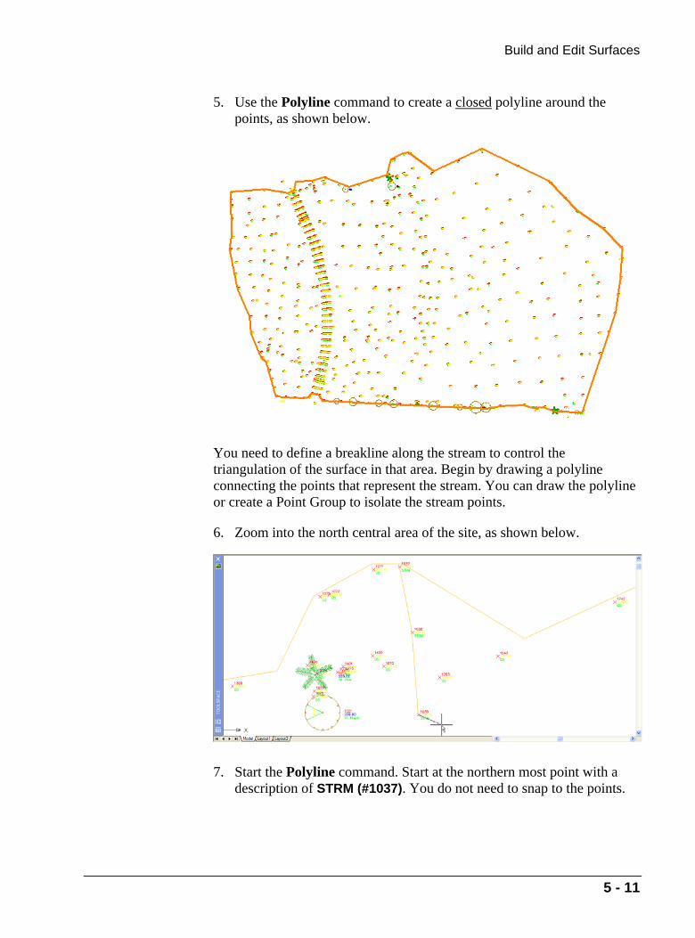
5. Use the Polyline command to create a closed polyline around the points, as shown below.
You need to define a breakline along the stream to control the triangulation of the surface in that area. Begin by drawing a polyline connecting the points that represent the stream. You can draw the polyline or create a Point Group to isolate the stream points.
6. Zoom into the north central area of the site, as shown below.
7. Start the Polyline command. Start at the northern most point with a description of STRM (#1037). You do not need to snap to the points.

Copyrighted Material
Copyrighted
Material
Copyrighted Material
Copyrighted
Material
Civil 3D 2008 Introduction to Corridor Design
5 - 12
8. Work south, picking near each STRM point. To make this process a little easier, the points are numbered sequentially from 1037 in the north to 1057 in the south. You now have the three components you will use to define the surface.

Copyrighted Material
Copyrighted
Material
Copyrighted Material
Copyrighted
Material
Build and Edit Surfaces
5 - 13
Add Point Groups
1. Expand Surfaces, EG, and Definition.
2. Right-click on EG and select Rebuild Automatic.
3. Right-click on Point Groups and select Add.
4. Select EG TOPO and click OK.
Copyrighted Material
Copyrighted
Material
Copyrighted Material
Copyrighted
Material
Civil 3D 2008 Introduction to Corridor Design
5 - 14
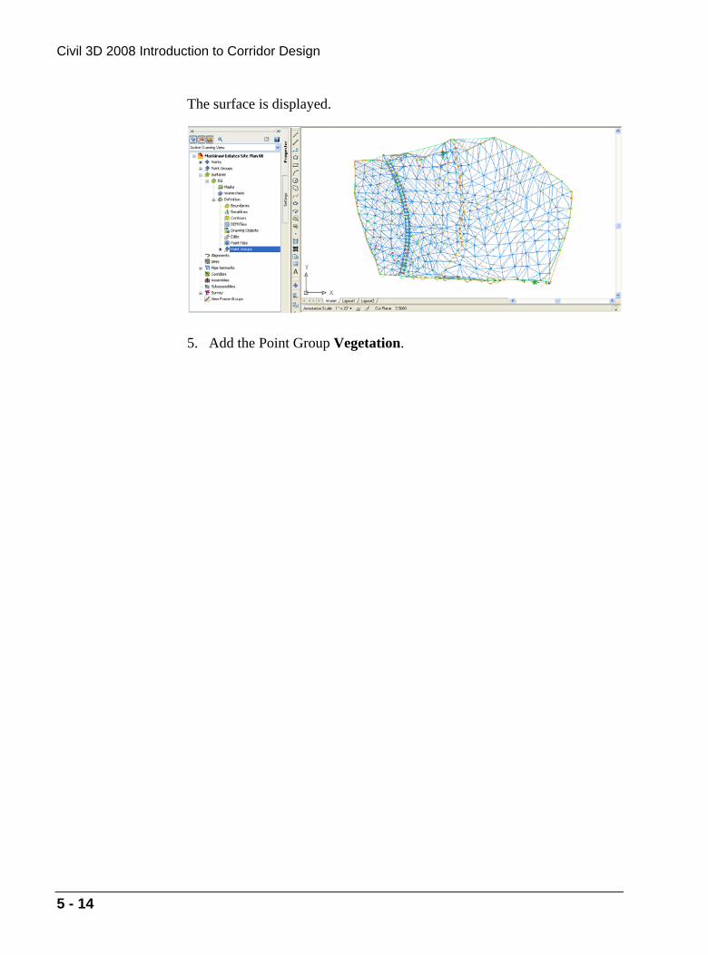
The surface is displayed.
5. Add the Point Group Vegetation.

Copyrighted Material
Copyrighted
Material
Copyrighted Material
Copyrighted
Material
Build and Edit Surfaces
5 - 15
Create a Boundary
The surface extends beyond the polyline for the boundary. You will now define the boundary.
1. Right-click on Boundaries and select Add.
2. Enter the Name EG Limits.
3. Select Outer for the Type.
4. Leave the Non-Destructive Breakline option cleared.
5. The Mid-ordinate distance value is irrelevant.
6. Click OK.
7. Select the polyline. Note how the surface border has changed.

Copyrighted Material
Copyrighted
Material
Copyrighted Material
Copyrighted
Material
Civil 3D 2008 Introduction to Corridor Design
5 - 16
8. Grip edit the boundary if you did not achieve the intended results.
Before
After

Copyrighted Material
Copyrighted
Material
Copyrighted Material
Copyrighted
Material
Build and Edit Surfaces
5 - 17
Create a Breakline
You will now add the breakline for the stream. The polylines for breaklines must be drawn before selecting this command.
1. Zoom to the northern half of the stream.
Some of the triangulation crossed the stream. This means a point on the top of one bank is interpolating to a point on the top of the other bank. You want the triangulation to follow the stream. A breakline resolves this.
2. Right-click on Breaklines and select Add.
3. Enter a Description of Trout Stream.
4. Set the Type to Proximity. The File link options and Mid-ordinate distance value are irrelevant. Click OK.

Copyrighted Material
Copyrighted
Material
Copyrighted Material
Copyrighted
Material
Civil 3D 2008 Introduction to Corridor Design
5 - 18
5. Select the polyline and press <Enter>.
The triangulation revises to follow the stream. The contours represent the stream more accurately.
Breaklines created by Proximity leave the original polylines in the drawing even though they are defined as a Standard breakline. This Standard definition can be inserted into the drawing and manipulated. The original line can be deleted.
A breakline created as a Standard breakline is linked to the original line in the drawing. If this line is deleted, the breakline definition is deleted. The different breakline definitions are described below.
Breakline Type Description Standard Creates a breakline that is defined by selecting 3D lines, grading
feature lines, and 3D polylines. Proximity Creates a breakline that is defined by drawing or selecting a
grading feature line or polyline within the extents of the surface boundary. The location and elevation of each vertex is determined by the nearest surface point.
Wall A wall breakline is stored as a standard breakline but is defined differently. You provide an offset side, elevation difference at a vertex or entire breakline.
Non-destructive Creates a breakline that is defined using grading feature lines and open or closed AutoCAD objects. A non-destructive breakline does not affect the original surface.