a adapters, planar dapters, planar & blind-mate& blind-mate … · 2005. 5. 18. · 5305...
TRANSCRIPT
197
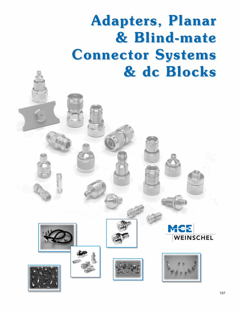
AAdapters, Planar dapters, Planar & Blind-mate& Blind-mate
Connector Systems Connector Systems & dc Blocks& dc Blocks

5305 Spectrum Drive, Frederick, MD 21703-7362 TEL: 301-846-9222, 800-638-2048 Fax: 301-846-9116web: www.weinschel.com email: [email protected]
4/30/02
MODEL CONNECTOR FREQUENCY SWR INSERTION REPEATABILITY PageNUMBER TYPE RANGE (MAXIMUM) LOSS No.
F1513 N female - N female dc - 18 1.10-1.15* <0.25 0.020 dB 203M1513 N male - N male
1548-13 SMA female - N female dc - 18 1.10 0.43 (maximum) Type N: 0.006-0.010* 2051548-14 SMA female - N male per mated pair SMA: 0.010-0.020*1548-23 SMA male - N female1548-24 SMA male - N male
1568 SMA (female-female) dc - 26.5 1.15-1.20* <0.30 - <0.50* 0.010-0.020* 201bulkhead (add -1 to modelnumber for stainless steel)
1587 SMA female - SMA female dc - 26.5 1.15-1.20* <0.30 - <0.50* 0.010-0.020* 2021588 SMA male - SMA female1589 SMA male - SMA male
7002-13 SMA female to N female dc - 18 1.12 <0.40 - <0.50* 0.010-0.020* 2047002-14 SMA female to N male7002-23 SMA male to N female7002-24 SMA male to N male
Model Connector Frequency Insertion Loss SWR PageNumber Type Type Range (GHz) Maximum (dB) (Maximum) No.
7003 Inside N 0.01 to 18 0.8 1.35-1.50* 2177006 SMA
7012 Inside/ SMA 0.5 to 8.6 0.4 1.25 218Outside
Express Shipment available. *Varies with frequency.
General InformationIn this section of the catalog, each product is outlined utilizing individual data sheets containing product features, spec-ifications, and outline drawings. These data sheets are preceded by a quick reference guide to help you select theproduct(s) that fits your needs. The page number for each product data sheet is given in the quick reference guide.
198
Precision Adapters...dc-26.5 GHz
Model Connector Frequency SWR Loss PageNumber Type Range (GHz) (Maximum) (Maximum dB) No.
7008 Pressurized SMA Female dc - 40.0 1.30-1.65* 0.3-1.5* 208
7034 2.92mm Female, dc - 40.0 1.35-1.55* 0.85 209Rear Lock, Floating
7034-1 2.92mm Female, dc - 40.0 1.35-1.55* 0.85 209Rear Lock, Fixed
7035 2.92mm Female, Front Locking dc - 40.0 1.35-1.55* 0.85 209Hex Nut, Floating
7035-1 2.92mm Female, Front Locking dc - 40.0 1.35-1.55* 0.85 209Hex Nut, Fixed
7035R 2.92mm Female, Front Locking, dc - 40.0 1.35-1.55* 0.85 209Floating, Round Nut
7035R-1 2.92mm Female, Front Locking, dc - 40.0 1.35-1.55* 0.85 209Fixed, Round Nut
Blind-Mate Connectors...dc-40.0 GHz
dc Blocks...dc to 18.0 GHz

5305 Spectrum Drive, Frederick, MD 21703-7362 TEL: 301-846-9222, 800-638-2048 Fax: 301-846-9116web: www.weinschel.com email: [email protected]
199
Model Number/ Frequency SWR* Insertion Loss * Electrical PagePrimary Conn. Range (GHz) (maximum) (dB maximum) Length No.
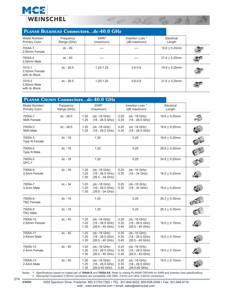
7004A-1 dc - 40 ---- ---- 19.9 + 0.25mm 2122.92mm Female
7004A-2 dc - 40 ---- ---- 21.6 + 0.25mm 2122.92mm Male
7010-1 dc - 26.5 1.20-1.25 0.6-0.9 19.9 + 0.25mm 2162.92mm Femalewith dc Block
7010-2 dc - 26.5 1.20-1.25 0.6-0.9 21.6 + 0.25mm 2162.92mm Malewith dc Block
PLANAR BULKHEAD Connectors...dc-40.0 GHz
Model Number/ Frequency SWR* Insertion Loss * Electrical PagePrimary Conn. Range (GHz) (maximum) (dB maximum) Length No.
7005A-1 dc - 26.5 1.20 (dc -18 GHz) 0.25 (dc -18 GHz) 18.6 + 0.25mm 212SMA Female 1.25 (18 - 26.5 GHz) 0.35 (18 - 26.5 GHz)
7005A-2 dc - 26.5 1.20 (dc -18 GHz) 0.25 (dc -18 GHz) 18.6 + 0.25mm 212SMA Male 1.25 (18 - 26.5 GHz) 0.35 (18 - 26.5 GHz)
7005A-3 dc - 18 1.20 0.25 18.6 + 0.25mm 212Type N Female
7005A-4 dc - 18 1.20 0.25 28.6 + 0.25mm 212Type N Male
7005A-5 dc - 18 1.20 0.25 34.8 + 0.25mm 212GPC-7
7005A-6 dc - 34 1.20 (dc -18 GHz) 0.25 (dc -18 GHz)3.5mm Female 1.25 (18 - 26.5 GHz) 0.35 (18 - 34 GHz) 18.0 + 0.20mm 212
1.30 (26.5 - 34 GHz)
7005A-7 dc - 34 1.20 (dc -18 GHz) 0.25 (dc -18 GHz)3.5mm Male 1.25 (18 - 26.5 GHz) 0.35 (18 - 34 GHz) 18.0 + 0.20mm 212
1.30 (26.5 - 34 GHz)
7005A-8 dc - 18 1.20 0.25 26.3 + 0.35mm 212TNC Female
7005A-9 dc - 18 1.20 0.25 28.6 + 0.35mm 212TNC Male
7005A-10 dc - 40 1.20 (dc -18 GHz) 0.25 (dc -18 GHz)2.92mm Female 1.25 (18 - 26.5 GHz) 0.35 (18 - 26.5 GHz) 18.0 + 0.15mm 212
1.35 (26.5 - 40 GHz) 0.45 (26.5 - 40 GHz)
7005A-11 dc - 40 1.20 (dc -18 GHz) 0.25 (dc -18 GHz)2.92mm Male 1.25 (18 - 26.5 GHz) 0.35 (18 - 26.5 GHz) 18.0 + 0.15mm 212
1.35 (26.5 - 40 GHz) 0.45 (26.5 - 40 GHz)
7005A-12 dc - 40 1.20 (dc -18 GHz) 0.25 (dc -18 GHz)2.4mm Female 1.25 (18 - 26.5 GHz) 0.35 (18 - 26.5 GHz) 18.0 + 0.15mm 212
1.35 (26.5 - 40 GHz) 0.45 (26.5 - 40 GHz)
7005A-13 dc - 40 1.20 (dc -18 GHz) 0.25 (dc -18 GHz) 18.0 + 0.15mm 2122.4mm Male 1.25 (18 - 26.5 GHz) 0.35 (18 - 26.5 GHz)
1.35 (26.5-40 GHz) 0.45 (26.5-40 GHz)
PLANAR CROWN Connectors...dc-40.0 GHz
4/30/02
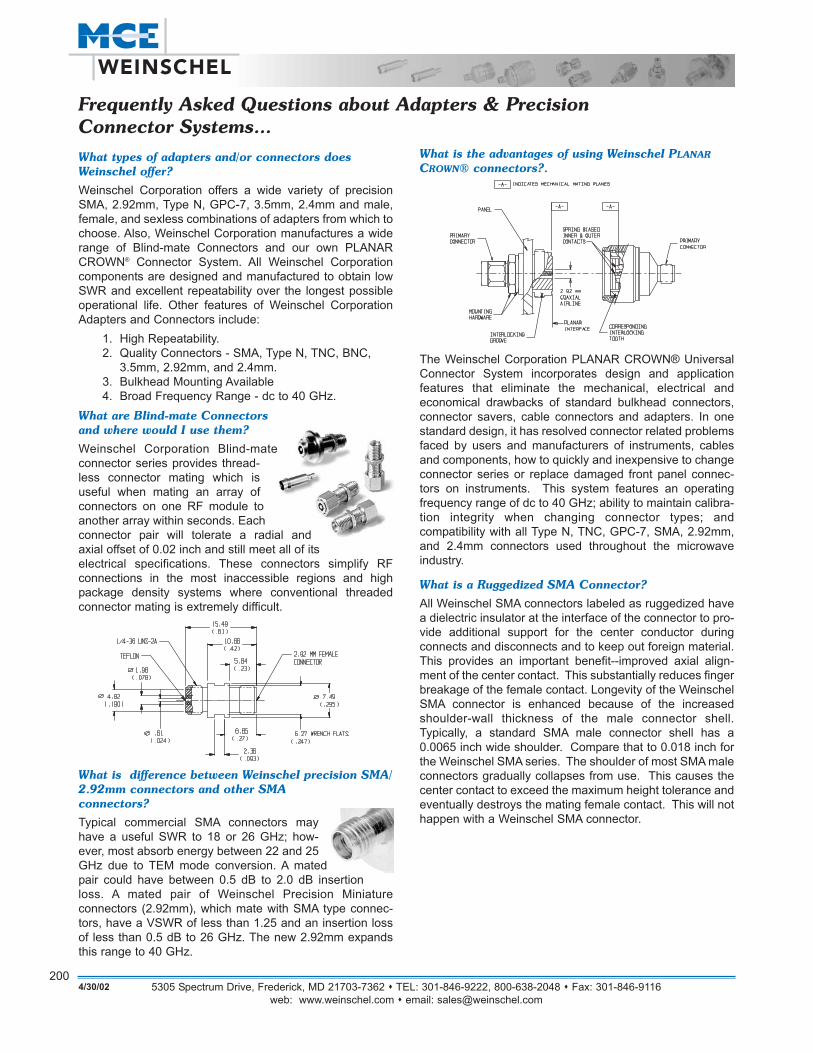
What is the advantages of using Weinschel PLANAR
CROWN® connectors?.
The Weinschel Corporation PLANAR CROWN® UniversalConnector System incorporates design and application features that eliminate the mechanical, electrical and economical drawbacks of standard bulkhead connectors,connector savers, cable connectors and adapters. In onestandard design, it has resolved connector related problemsfaced by users and manufacturers of instruments, cablesand components, how to quickly and inexpensive to changeconnector series or replace damaged front panel connec-tors on instruments. This system features an operatingfrequency range of dc to 40 GHz; ability to maintain calibra-tion integrity when changing connector types; andcompatibility with all Type N, TNC, GPC-7, SMA, 2.92mm,and 2.4mm connectors used throughout the microwaveindustry.
What is a Ruggedized SMA Connector?
All Weinschel SMA connectors labeled as ruggedized havea dielectric insulator at the interface of the connector to pro-vide additional support for the center conductor duringconnects and disconnects and to keep out foreign material.This provides an important benefit--improved axial align-ment of the center contact. This substantially reduces fingerbreakage of the female contact. Longevity of the WeinschelSMA connector is enhanced because of the increasedshoulder-wall thickness of the male connector shell.Typically, a standard SMA male connector shell has a0.0065 inch wide shoulder. Compare that to 0.018 inch forthe Weinschel SMA series. The shoulder of most SMA maleconnectors gradually collapses from use. This causes thecenter contact to exceed the maximum height tolerance andeventually destroys the mating female contact. This will nothappen with a Weinschel SMA connector.
5305 Spectrum Drive, Frederick, MD 21703-7362 TEL: 301-846-9222, 800-638-2048 Fax: 301-846-9116web: www.weinschel.com email: [email protected]
200
What types of adapters and/or connectors doesWeinschel offer?
Weinschel Corporation offers a wide variety of precisionSMA, 2.92mm, Type N, GPC-7, 3.5mm, 2.4mm and male,female, and sexless combinations of adapters from which tochoose. Also, Weinschel Corporation manufactures a widerange of Blind-mate Connectors and our own PLANARCROWN® Connector System. All Weinschel Corporationcomponents are designed and manufactured to obtain lowSWR and excellent repeatability over the longest possibleoperational life. Other features of Weinschel CorporationAdapters and Connectors include:
1. High Repeatability.2. Quality Connectors - SMA, Type N, TNC, BNC,
3.5mm, 2.92mm, and 2.4mm. 3. Bulkhead Mounting Available4. Broad Frequency Range - dc to 40 GHz.
What are Blind-mate Connectorsand where would I use them?
Weinschel Corporation Blind-mateconnector series provides thread-less connector mating which isuseful when mating an array ofconnectors on one RF module toanother array within seconds. Each connector pair will tolerate a radial and axial offset of 0.02 inch and still meet all of itselectrical specifications. These connectors simplify RF connections in the most inaccessible regions and highpackage density systems where conventional threaded connector mating is extremely difficult.
What is difference between Weinschel precision SMA/2.92mm connectors and other SMAconnectors?
Typical commercial SMA connectors mayhave a useful SWR to 18 or 26 GHz; how-ever, most absorb energy between 22 and 25GHz due to TEM mode conversion. A matedpair could have between 0.5 dB to 2.0 dB insertionloss. A mated pair of Weinschel Precision Miniature connectors (2.92mm), which mate with SMA type connec-tors, have a VSWR of less than 1.25 and an insertion lossof less than 0.5 dB to 26 GHz. The new 2.92mm expandsthis range to 40 GHz.
Frequently Asked Questions about Adapters & PrecisionConnector Systems...
4/30/02

Model 1568 & 1568-1 dc to 26.5 GHzOEM Precision Coaxial Panel Adapter
Ruggedized SMA Connectors (female to female)
Featureso High Repeatability.o Rugged Injection Molded Connectors.o Bulkhead Mounting - Conveniently mounts on any
panel using a D-hole shown below. Extra heavy construction for long life even with mistreatment makesthis adapter suitable for instrument and subsystem frontpanel applications.
SpecificationsNOMINAL IMPEDANCE: 50 ΩFREQUENCY RANGE: dc to 26.5 GHz
TEMPERATURE RANGE: -55°C to +125°CCONSTRUCTION: Inner and outer conductors: heat treatedberyllium copper, gold plated. Mounting hardware provided(Hex nut and lockwasher) Add -1 to model number for theoptional stainless steel body.CONNECTORS: SMA connectors per MIL-STD-348 inter-face dimensions - mate nondestructively with MIL-C-39012connectors.WEIGHT: 56.7 g (2 oz) maximumPHYSICAL DIMENSIONS:
MAXIMUM SWR:Frequency (GHz) SWRdc - 18 1.1518 - 26.5 1.20
Frequency (GHz) Ins Loss Repeatabilitydc - 12.4 < 0.30 0.0112.4 - 18 < 0.40 0.0218.0 to 26.5 < 0.50 0.02
INSERTION LOSS & REPEATABILITY (dB):
NOTE: All dimensions are given in mm (inches) and are maximum, unless otherwise specified.
5305 Spectrum Drive, Frederick, MD 21703-7362 TEL: 301-846-9222, 800-638-2048 Fax: 301-846-9116web: www.weinschel.com email: [email protected]
2014/30/02
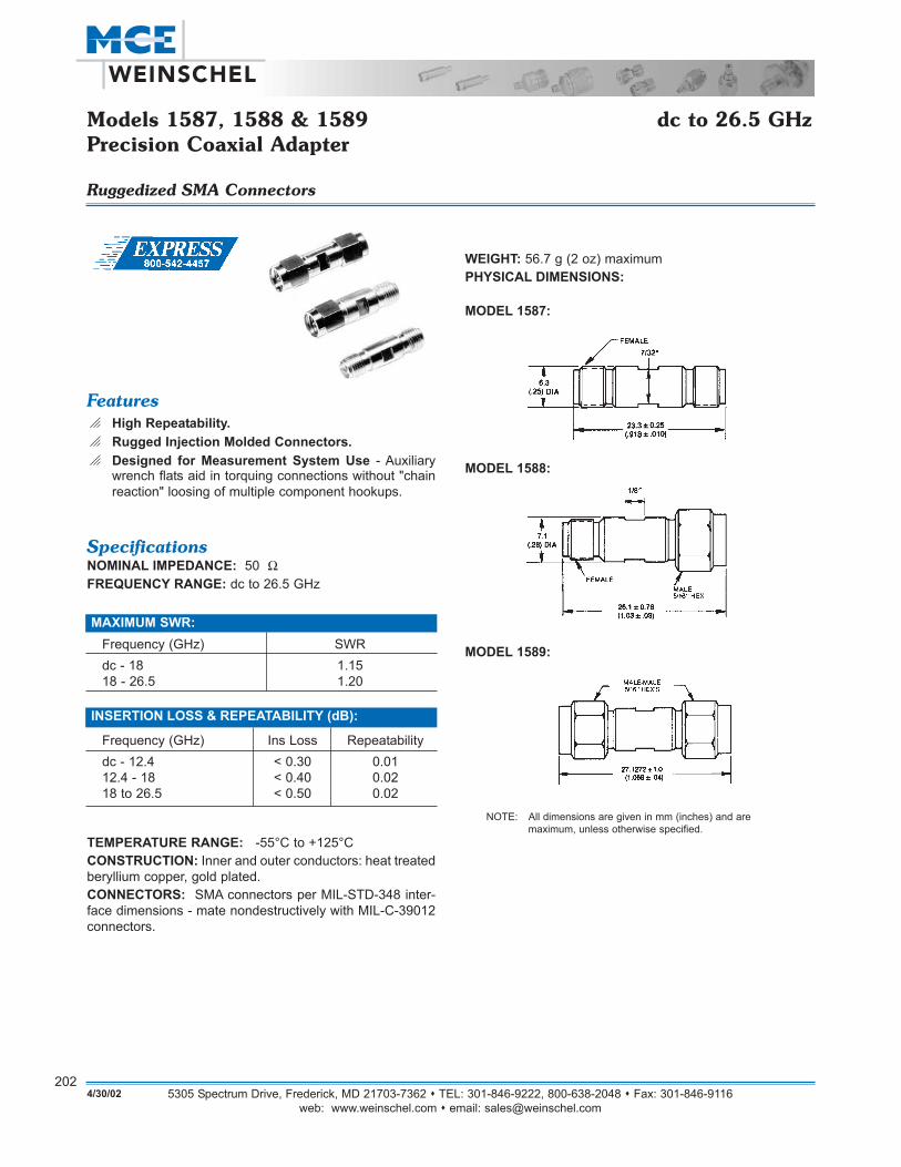
Models 1587, 1588 & 1589 dc to 26.5 GHzPrecision Coaxial Adapter
Ruggedized SMA Connectors
Featureso High Repeatability.o Rugged Injection Molded Connectors.o Designed for Measurement System Use - Auxiliary
wrench flats aid in torquing connections without "chainreaction" loosing of multiple component hookups.
SpecificationsNOMINAL IMPEDANCE: 50 ΩFREQUENCY RANGE: dc to 26.5 GHz
TEMPERATURE RANGE: -55°C to +125°CCONSTRUCTION: Inner and outer conductors: heat treatedberyllium copper, gold plated. CONNECTORS: SMA connectors per MIL-STD-348 inter-face dimensions - mate nondestructively with MIL-C-39012connectors.
MAXIMUM SWR:Frequency (GHz) SWRdc - 18 1.1518 - 26.5 1.20
Frequency (GHz) Ins Loss Repeatabilitydc - 12.4 < 0.30 0.0112.4 - 18 < 0.40 0.0218 to 26.5 < 0.50 0.02
INSERTION LOSS & REPEATABILITY (dB):
MODEL 1588:
MODEL 1589:
WEIGHT: 56.7 g (2 oz) maximumPHYSICAL DIMENSIONS:
MODEL 1587:
NOTE: All dimensions are given in mm (inches) and are maximum, unless otherwise specified.
5305 Spectrum Drive, Frederick, MD 21703-7362 TEL: 301-846-9222, 800-638-2048 Fax: 301-846-9116web: www.weinschel.com email: [email protected]
2024/30/02
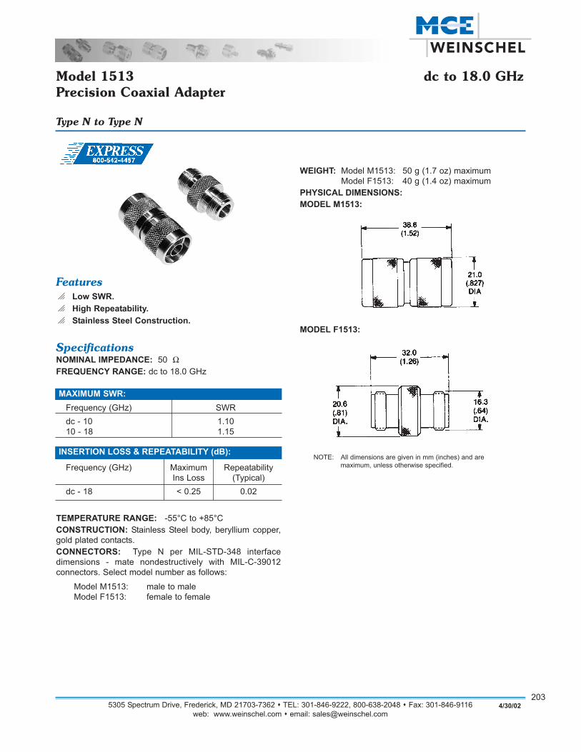
Model 1513 dc to 18.0 GHzPrecision Coaxial Adapter
Type N to Type N
Featureso Low SWR.o High Repeatability.o Stainless Steel Construction.
SpecificationsNOMINAL IMPEDANCE: 50 ΩFREQUENCY RANGE: dc to 18.0 GHz
TEMPERATURE RANGE: -55°C to +85°CCONSTRUCTION: Stainless Steel body, beryllium copper,gold plated contacts. CONNECTORS: Type N per MIL-STD-348 interfacedimensions - mate nondestructively with MIL-C-39012 connectors. Select model number as follows:
Model M1513: male to male Model F1513: female to female
MAXIMUM SWR:Frequency (GHz) SWRdc - 10 1.1010 - 18 1.15
MODEL F1513:
WEIGHT: Model M1513: 50 g (1.7 oz) maximumModel F1513: 40 g (1.4 oz) maximum
PHYSICAL DIMENSIONS:MODEL M1513:
Frequency (GHz) Maximum RepeatabilityIns Loss (Typical)
dc - 18 < 0.25 0.02
INSERTION LOSS & REPEATABILITY (dB):NOTE: All dimensions are given in mm (inches) and are
maximum, unless otherwise specified.
5305 Spectrum Drive, Frederick, MD 21703-7362 TEL: 301-846-9222, 800-638-2048 Fax: 301-846-9116web: www.weinschel.com email: [email protected]
2034/30/02
Model 7002 dc to 18.0 GHzHigh Performance Coaxial Adapter
Ruggedized SMA to Type N
Featureso High Repeatabilityo Rugged Injection Molded Connectorso Stainless Steel Construction
SpecificationsNOMINAL IMPEDANCE: 50 ΩFREQUENCY RANGE: dc to 18.0 GHz
ELECTRICAL LENGTH:Models 7002-14 & 7002-24: 33mmModels 7002-13 & 7002-23: 20mm
CONSTRUCTION: Gold plated beryllium copper centerconductors, injection molded into stainless steel outer bodies.CONNECTORS: Type N and SMA connectors per MIL-STD-348 interface dimensions - mate nondestructivelywith MIL-C-39012 connectors. WEIGHT: 30 g (1.1 oz) maximum
MAXIMUM SWR:Frequency (GHz) SWR (per adapter)dc - 18 1.12
Frequency (GHz) Ins Loss* Repeatability*dc - 12.4 < 0.40 0.0112.4 - 18 < 0.50 0.02
*Specification based on mated pair terminated in 50 Ω.
INSERTION LOSS & REPEATABILITY (dB):
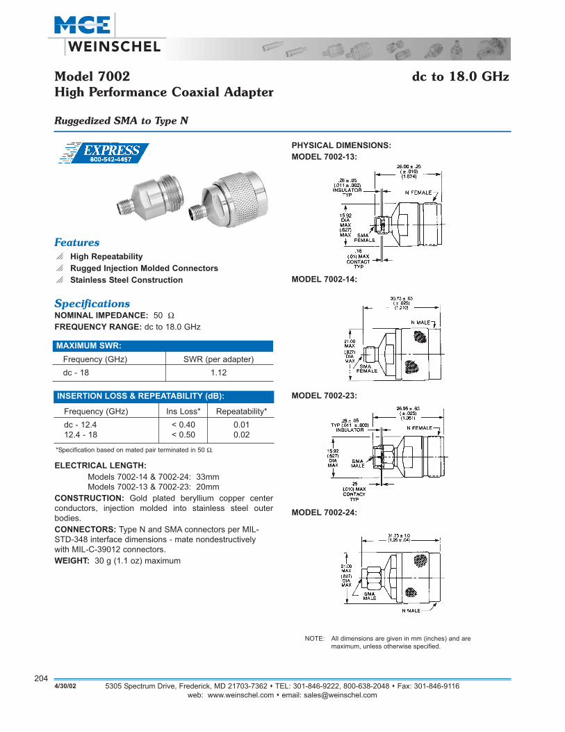
MODEL 7002-14:
PHYSICAL DIMENSIONS:MODEL 7002-13:
MODEL 7002-24:
MODEL 7002-23:
NOTE: All dimensions are given in mm (inches) and are maximum, unless otherwise specified.
5305 Spectrum Drive, Frederick, MD 21703-7362 TEL: 301-846-9222, 800-638-2048 Fax: 301-846-9116web: www.weinschel.com email: [email protected]
2044/30/02

Model 1548 dc to 18.0 GHzPrecision Coaxial Adapter
SMA to Type N
Featureso High Repeatabilityo Rugged Constructiono Stainless Steel Construction
SpecificationsNOMINAL IMPEDANCE: 50 ΩFREQUENCY RANGE: dc to 18.0 GHz
TEMPERATURE RANGE: -55°C to + 85°C CONSTRUCTION: Stainless steel body and coupling nuts.Gold plated beryllium copper center conductors and SMAbodies, injection molded insulators. Coupling Torque: 14 + 1inch pounds for Type N and 8+0.5 inch pounds for SMA. CONNECTORS: Type N and SMA connectors per MIL-STD-348 interface dimensions - mate nondestructively withMIL-C-39012 connectors. WEIGHT: 56.7 g (2 oz) maximum connectors only.
MAXIMUM SWR:Frequency (GHz) SWR*dc - 18 1.10
Frequency (GHz) Type N SMAdc - 12.4 < 0.006 0.0112.4 - 18 < 0.010 0.02
* Specification based on mated pair terminated in 50 Ω.
REPEATABILITY (dB):
MODEL 1548-24
PHYSICAL DIMENSIONS:
MODEL 1548-13MODEL 1548-23
INSERTION LOSS (dB):Frequency (GHz) Loss (maximum)*dc - 18 <0.43
MODEL 1548-14
NOTE: All dimensions are given in mm (inches) and are maximum, unless otherwise specified.
5305 Spectrum Drive, Frederick, MD 21703-7362 TEL: 301-846-9222, 800-638-2048 Fax: 301-846-9116web: www.weinschel.com email: [email protected]
2054/30/02
Models 7008, 7034, 7035 & 7035R dc to 40.0 GHzPlanar Blind-MateTM Connectors
Space Saving, Long Life, Threadless Connector Mating System
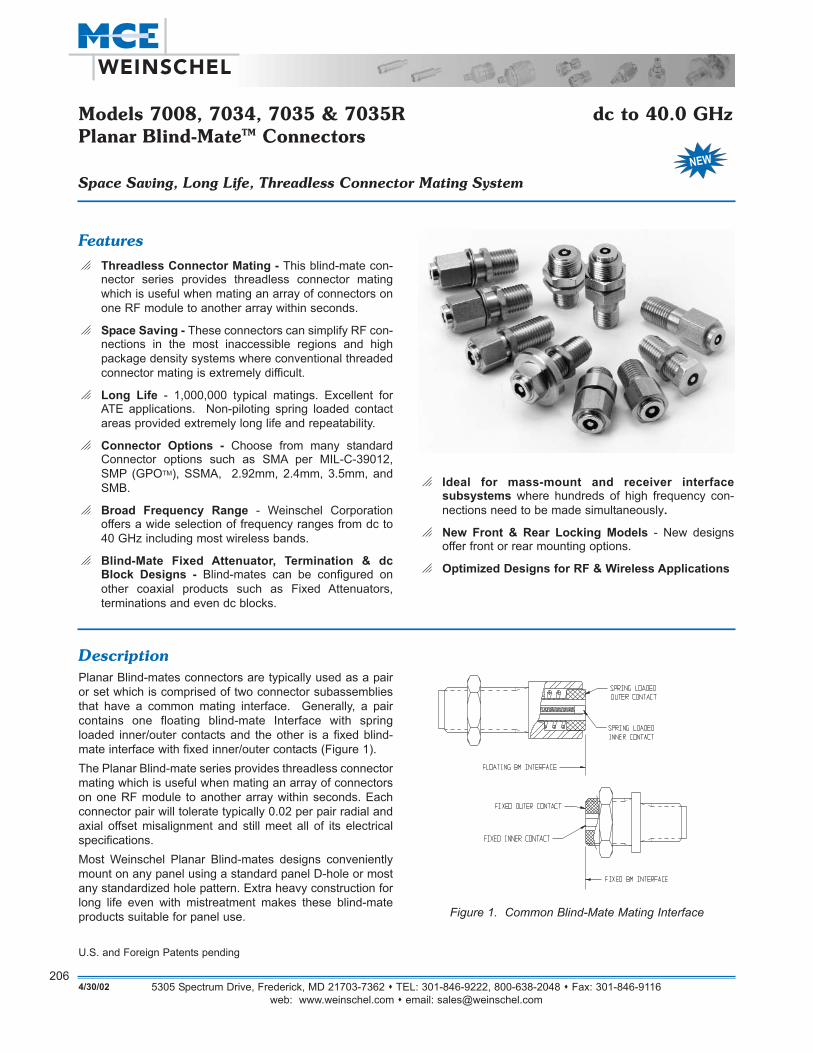
DescriptionPlanar Blind-mates connectors are typically used as a pairor set which is comprised of two connector subassembliesthat have a common mating interface. Generally, a paircontains one floating blind-mate Interface with springloaded inner/outer contacts and the other is a fixed blind-mate interface with fixed inner/outer contacts (Figure 1).The Planar Blind-mate series provides threadless connectormating which is useful when mating an array of connectorson one RF module to another array within seconds. Eachconnector pair will tolerate typically 0.02 per pair radial andaxial offset misalignment and still meet all of its electricalspecifications. Most Weinschel Planar Blind-mates designs convenientlymount on any panel using a standard panel D-hole or mostany standardized hole pattern. Extra heavy construction forlong life even with mistreatment makes these blind-mateproducts suitable for panel use.
5305 Spectrum Drive, Frederick, MD 21703-7362 TEL: 301-846-9222, 800-638-2048 Fax: 301-846-9116web: www.weinschel.com email: [email protected]
2064/30/02
Featureso Threadless Connector Mating - This blind-mate con-
nector series provides threadless connector matingwhich is useful when mating an array of connectors onone RF module to another array within seconds.
o Space Saving - These connectors can simplify RF con-nections in the most inaccessible regions and highpackage density systems where conventional threadedconnector mating is extremely difficult.
o Long Life - 1,000,000 typical matings. Excellent forATE applications. Non-piloting spring loaded contactareas provided extremely long life and repeatability.
o Connector Options - Choose from many standardConnector options such as SMA per MIL-C-39012,SMP (GPOTM), SSMA, 2.92mm, 2.4mm, 3.5mm, andSMB.
o Broad Frequency Range - Weinschel Corporationoffers a wide selection of frequency ranges from dc to40 GHz including most wireless bands.
o Blind-Mate Fixed Attenuator, Termination & dcBlock Designs - Blind-mates can be configured onother coaxial products such as Fixed Attenuators, terminations and even dc blocks.
o Ideal for mass-mount and receiver interface subsystems where hundreds of high frequency con-nections need to be made simultaneously.
o New Front & Rear Locking Models - New designsoffer front or rear mounting options.
o Optimized Designs for RF & Wireless Applications
Figure 1. Common Blind-Mate Mating Interface
U.S. and Foreign Patents pending

5305 Spectrum Drive, Frederick, MD 21703-7362 TEL: 301-846-9222, 800-638-2048 Fax: 301-846-9116web: www.weinschel.com email: [email protected]
2074/30/02
ApplicationsIdeal applications for these high quality/high frequency connectors range from mass-mount and receiver interface subsys-tems that house hundreds of high frequency connectors to single connector configurations. In either case these connectorsallow threadless connector mating which is very useful when mating an array of connectors on one RF module to anotherarray or connector within seconds.
Figure 2 shows a typical application where each connector half contains 7035R series connectors. These connectors con-tain spring loaded inner/outer contacts which allows for extremely long contact life as well as 0.02 per pair maximum radialand axial offset misalignment while still meeting all the specified electrical specifications.
Weinschel offers a variety of standard models which are designed to fit or be configured into a wide range of applications:
o Pressurized Designs - Model 7008 (page 208) is equipped with a flange arrangement designed to withstand 1000 PSIof hydrostatic pressure. This model can be mated with another 7008 or any 7034 or 7035 series Planar Blind-mate. Seepage 208 for mating applications.
o Rear Locking - Models 7034 & 7034-1 (page 209) are beneficial in applications where there is easy access to the frontof the connector for holding while the cable and connector is added or removed. Rotation is also prevented if the connector front is inserted in a slot which could allow for easier cable and connector assembly installation.
o Front Locking - Models 7035, 7035-1, 7035R & 7035R-1 (page 209) are beneficial in applications where the cable andconnector will be inserted as an assembly into a panel or connector module from the rear.
o Custom Configurations - Other types of Planar Blind-mate connectors such as SMA, SMB, 3.5mm, flange,microstrip/pc board mount launch, test probes, frequency specific, arrays or interface subsystems can be designed foryour particular application. Refer to page 210-211 for other examples.
Figure 2. Typical Application
5305 Spectrum Drive, Frederick, MD 21703-7362 TEL: 301-846-9222, 800-638-2048 Fax: 301-846-9116web: www.weinschel.com email: [email protected]
2084/30/02
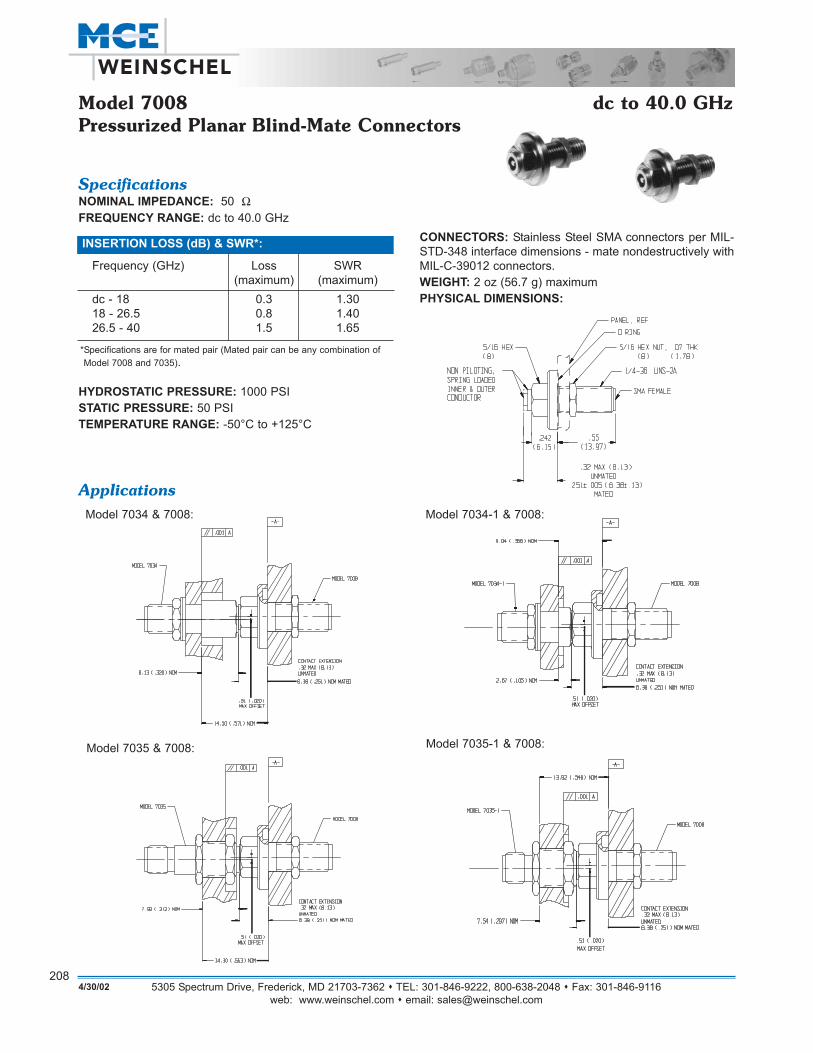
Model 7008 dc to 40.0 GHzPressurized Planar Blind-Mate Connectors
SpecificationsNOMINAL IMPEDANCE: 50 ΩFREQUENCY RANGE: dc to 40.0 GHz
Frequency (GHz) Loss SWR(maximum) (maximum)
dc - 18 0.3 1.3018 - 26.5 0.8 1.4026.5 - 40 1.5 1.65
*Specifications are for mated pair (Mated pair can be any combination ofModel 7008 and 7035).
INSERTION LOSS (dB) & SWR*:
HYDROSTATIC PRESSURE: 1000 PSI STATIC PRESSURE: 50 PSITEMPERATURE RANGE: -50°C to +125°C
CONNECTORS: Stainless Steel SMA connectors per MIL-STD-348 interface dimensions - mate nondestructively withMIL-C-39012 connectors.WEIGHT: 2 oz (56.7 g) maximumPHYSICAL DIMENSIONS:
ApplicationsModel 7034 & 7008:
Model 7035 & 7008:
Model 7034-1 & 7008:
Model 7035-1 & 7008:
5305 Spectrum Drive, Frederick, MD 21703-7362 TEL: 301-846-9222, 800-638-2048 Fax: 301-846-9116web: www.weinschel.com email: [email protected]
4/30/02209
SpecificationsNOMINAL IMPEDANCE: 50 ΩFREQUENCY RANGE: dc to 40.0 GHz
INSERTION LOSS REPEATABILITY: +0.1 dB typicalMECHANICAL LIFE: 25,000 matings minimumRADIAL OFFSET ALLOWED: +0.02 per pairTEMPERATURE RANGE: -50°C to +100°CCONNECTORS: Stainless Steel 2.92mm connector withgold plated contactsWEIGHT: 2 oz, (56.7 g) maximum
Frequency (GHz) Loss SWR(maximum) (maximum)
dc - 18 0.85 1.3518 - 40 0.85 1.55
INSERTION LOSS (dB) & SWR:
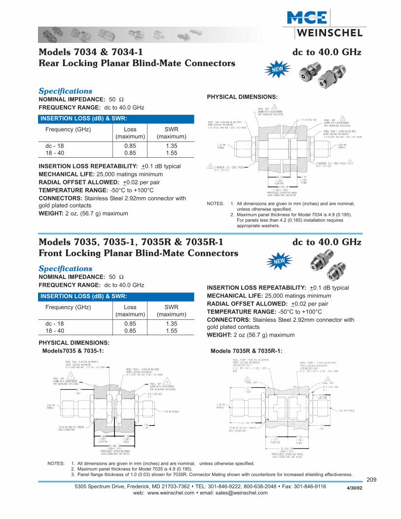
PHYSICAL DIMENSIONS:
Models 7034 & 7034-1 dc to 40.0 GHzRear Locking Planar Blind-Mate Connectors
NOTES: 1. All dimensions are given in mm (inches) and are nominal, unless otherwise specified.
2. Maximum panel thickness for Model 7034 is 4.9 (0.195). For panels less than 4.2 (0.165) installation requires appropriate washers.
SpecificationsNOMINAL IMPEDANCE: 50 ΩFREQUENCY RANGE: dc to 40.0 GHz INSERTION LOSS REPEATABILITY: +0.1 dB typical
MECHANICAL LIFE: 25,000 matings minimumRADIAL OFFSET ALLOWED: +0.02 per pairTEMPERATURE RANGE: -50°C to +100°CCONNECTORS: Stainless Steel 2.92mm connector withgold plated contactsWEIGHT: 2 oz (56.7 g) maximum
Models 7035R & 7035R-1:
Frequency (GHz) Loss SWR(maximum) (maximum)
dc - 18 0.85 1.3518 - 40 0.85 1.55
INSERTION LOSS (dB) & SWR:
PHYSICAL DIMENSIONS:Models7035 & 7035-1:
Models 7035, 7035-1, 7035R & 7035R-1 dc to 40.0 GHzFront Locking Planar Blind-Mate Connectors
NOTES: 1. All dimensions are given in mm (inches) and are nominal, unless otherwise specified.2. Maximum panel thickness for Model 7035 is 4.9 (0.195). 3. Panel flange thickness of 1.0 (0.03) shown for 7035R. Connector Mating shown with counterbore for increased shielding effectiveness.

Example 4:
This example illustrates shows a 6 dB blind-mate attenuatordesign that consists of two floating receivers with a com-pression spring and spring loaded contacts (inner and outerconductors). Designs can also be supplied with stationaryfixed surface connectors. Specifications for this unit includedc-32 GHz operation, 1.35 maximum SWR, and a radialalignment +0.02 offset.
Example 5:
This example illustrates a blind-mate to 2.92mm connectordesign that features a non-piloting, spring loaded inner andouter connector. Specifications included dc to 40 GHzfrequency operation, static pressure of 50 PSI, temperaturerange of -50°C to +125°C maximum insertion loss of 0.3 to1.5 and maximum SWR of 1.30-1.70.
Example 1:
This example shows a blind-mate to SMA flange connectorwhich includes a standard 4 hole mounting pattern andSMA connectors per MIL-C-39012 connectors. These con-nectors can be optimized to a specific frequency rangeand/or your defined specifications. Example 2:
Example 2 illustrates a blind-mate to a microstrip launchdesign that features a non-piloting (fixed), spring loadedinner connector. Specifications include dc to 4 GHz fre-quency operation, maximum insertion loss of 0.5 dB andmaximum SWR of 1.25. Example 3:
Example 3 illustrates a blind-mate to 2.92mm test probedesign that features wrench flats, dc to 18 GHz frequencyoperation, maximum insertion loss of 6 dB and maximumSWR of 1.25. This was specifically designed to interfacewith standard SMA, 3.5mm, and 2.92mm Bulkhead connectors.
Custom ExamplesThe following examples illustrate some typical Blind-mate designs that can be either modified or used as a basis for creating a specific blind-mate connector or system for your application:
5305 Spectrum Drive, Frederick, MD 21703-7362 TEL: 301-846-9222, 800-638-2048 Fax: 301-846-9116web: www.weinschel.com email: [email protected]
2104/30/02

Example 6:
A
B
C
Example 3 shows a blind-mate connector sys-tem that was designed to interface with manydifferent specified requirements.
Connector A is a 3.5mm to blind-mate inter-face which contains fixed inner and outercontacts; used for connection to other coaxialcomponents such as attenuators, terminationsand dc blocks.
Connector B is a blind-mate to 2.92mm paneladapter design with a spring loaded inner andouter contacts.
Connector C is a blind-mate interface connec-tor that can be easily installed to coaxialcables or printed circuit board assemblies.
NOTE: All dimensions are given in mm (inches) and are maximum, unless otherwise specified.
5305 Spectrum Drive, Frederick, MD 21703-7362 TEL: 301-846-9222, 800-638-2048 Fax: 301-846-9116web: www.weinschel.com email: [email protected]
2114/30/02
Example 7:
This example illustrates a low cost blind-mate to SMB con-figuration specifically designed and optimized for RF &wireless applications. These connectors offer not only allthe features of the Planar Blind-mate interface but the SMBconnector provides an additional quick disconnect for cableassemblies.
Specifications for this connector include dc to 2.0 GHz oper-ation, 50 Ω nominal impedance, insertion loss of 0.35 dB,SWR of 1.15-1.30, radial/axial misalignment of +0.020”OFFSET (blind-mate side), operating temperature of+10°C to +40°C, dielectric withstanding voltage of 1000 Vacand a insulation resistance of 1000 MΩΩ nominal.
These stainless steel connectors contain non-piloting con-tacts that provides long life (1,000,000 matings) and offersa repeatability of +0.05 dB typical.

Models 7004 & 7005 dc to 40.0 GHzPlanar Crown® Universal Connector System
SMA; Type N; TNC; GPC-7; 3.5mm; 2.92mm; 2.4mm
DescriptionThe PLANAR CROWN® Universal Connector System is comprised of two connector halves/subassemblies whichhave a common mating interface referred to as the PLANARINTERFACE. The first connector half is called the PLANARBULKHEAD which readily mounts into instrument front panels, components and cables. One end of this bulkheadhas a 2.92mm male/female primary connector. The otherend has a combination of grooves, external threads and acoaxial PLANAR INTERFACE with a 2.92mm airline geometry.The bulkhead operates mode free beyond 40 GHz. Thesecond connector half, called the PLANAR CROWN®, has asimilar 2.92mm PLANAR INTERFACE on one end, with springbiased inner and outer contacts. It has corresponding projections which interlock with slots on the bulkhead and acoupling nut which secures the two connector halves,resulting in a non-rotational, torque independent electricalconnection. The spring biased inner and outer contactseliminate the need for specifying proof torque and no toolsare required to make or break the connection. The primary
end of the PLANAR CROWN® is offered in a variety of primarycoaxial connector configurations such as SMA, Type N,GPC-7, TNC, 3.5mm, 2.92mm and 2.4mm (under develop-ment), thus providing an extremely versatile connectorsystem wherein a connector can be replaced in a matter ofseconds.
FeaturesThe use of PLANAR CROWN® connectors on instruments,cables, components/accessories offers the manufacturerand user the following benefits.Reduced Downtime - Damaged connectors can bereplaced in seconds without any tools. Repair cost is mini-mized to that of a single connector. Recalibration, in mostapplications, is virtually eliminated due to closely matchedphase, mechanical dimensions and insertion loss of thereplaceable PLANAR CROWN® assemblies.Versatility - Ability to select different connector types addsversatility to instruments, cables, systems and accessories.It offers the end user multiple connector options. Connectortype and sex can be readily interchanged as dictated by thesystem/DUT, eliminating the need for adapters.Superior Electrical Performance than would be obtainedby additional adapters.Simplified Network and Power Measurements on non-insertable devices.Non-rotational Interface - Since the PLANAR INTERFACE hasinterlocking teeth, it eliminates unthreading of the connec-tion when the Crown is subjected to a rotational torque. Thisfeature is especially useful on coaxial cables where one endunthreads so easily when the cable is subjected to twistingor flexing.Torque Independent Connection - A torque wrench is notrequired when mating the Crown to the bulkhead. Areasonable hand tightening of the coupling nut results in anexcellent RF connection. This is achieved by having springbiased inner and outer contacts in the Crown connectors.Spring biasing ensures an intimate electrical contact at thePLANAR INTERFACE. A pilot diameter on the bulkhead guarantees excellent concentricity.Axial Isolation of the Center Contact - Any excessiveaxial force on the Crown center contact is absorbed by thespring biasing at the Planar interface end.Standardized Mounting Holes - All instrument panels canbe fabricated with a standard 3/8" Dia. D-hole independentof the front panel connector type/sex. This eliminateschanges in sheet metal design when different connectoroptions are requested.
5305 Spectrum Drive, Frederick, MD 21703-7362 TEL: 301-846-9222, 800-638-2048 Fax: 301-846-9116web: www.weinschel.com email: [email protected]
2124/30/02

Specifications
U.S. Patent No. 4,836,801 (Other U.S. and Foreign Patents pending)
NOTES: 1. All dimensions are given in mm (inches) and are nominal, unless otherwise specified.2. K® is a registered trademark of the Wiltron 2.92mm connector
PLANAR BULKHEAD CONNECTORS
PLANAR CROWN CONNECTORS
5305 Spectrum Drive, Frederick, MD 21703-7362 TEL: 301-846-9222, 800-638-2048 Fax: 301-846-9116web: www.weinschel.com email: [email protected]
2134/30/02
Model Number/ Frequency SWR* Insertion Loss * ElectricalPrimary Conn. Range (GHz) (maximum) (dB maximum) Length
7004A-1 dc - 40 ---- ---- 19.9 + 0.25mm2.92mm Female
7004A-2 dc - 40 ---- ---- 21.6 + 0.25mm2.92mm Male
7010-1 dc - 26.5 1.20-1.25 0.6-0.9 19.9 + 0.25mm2.92mm Femalewith dc Block
7010-2 dc - 26.5 1.20-1.25 0.6-0.9 21.6 + 0.25mm2.92mm Malewith dc Block
PLANAR BULKHEAD Connectors...dc-40.0 GHz
Model Number/ Frequency SWR* Insertion Loss * ElectricalPrimary Conn. Range (GHz) (maximum) (dB maximum) Length
7005A-1 dc - 26.5 1.20 (dc -18 GHz) 0.25 (dc -18 GHz) 18.6 + 0.25mmSMA Female 1.25 (18 - 26.5 GHz) 0.35 (18 - 26.5 GHz)
7005A-2 dc - 26.5 1.20 (dc -18 GHz) 0.25 (dc -18 GHz) 18.6 + 0.25mmSMA Male 1.25 (18 - 26.5 GHz) 0.35 (18 - 26.5 GHz)
7005A-3 dc - 18 1.20 0.25 18.6 + 0.25mmType N Female
7005A-4 dc - 18 1.20 0.25 28.6 + 0.25mmType N Male
7005A-5 dc - 18 1.20 0.25 34.8 + 0.25mmGPC-7
7005A-6 dc - 34 1.20 (dc -18 GHz) 0.25 (dc -18 GHz)3.5mm Female 1.25 (18 - 26.5 GHz) 0.35 (18 - 34 GHz) 18.0 + 0.20mm
1.30 (26.5 - 34 GHz)
7005A-7 dc - 34 1.20 (dc -18 GHz) 0.25 (dc -18 GHz)3.5mm Male 1.25 (18 - 26.5 GHz) 0.35 (18 - 34 GHz) 18.0 + 0.20mm
1.30 (26.5 - 34 GHz)
7005A-8 dc - 18 1.20 0.25 26.3 + 0.35mmTNC Female
7005A-9 dc - 18 1.20 0.25 26.3 + 0.35mmTNC Male
7005A-10 dc - 40 1.20 (dc -18 GHz) 0.25 (dc -18 GHz)2.92mm Female 1.25 (18 - 26.5 GHz) 0.35 (18 - 26.5 GHz) 18.0 + 0.15mm
1.35 (26.5 - 40 GHz) 0.45 (26.5 - 40 GHz)
7005A-11 dc - 40 1.20 (dc -18 GHz) 0.25 (dc -18 GHz)2.92mm Male 1.25 (18 - 26.5 GHz) 0.35 (18 - 26.5 GHz) 18.0 + 0.15mm
1.35 (26.5 - 40 GHz) 0.45 (26.5 - 40 GHz)
7005A-12 dc - 40 1.20 (dc -18 GHz) 0.25 (dc -18 GHz)2.4mm Female 1.25 (18 - 26.5 GHz) 0.35 (18 - 26.5 GHz) 18.0 + 0.15mm
1.35 (26.5 - 40 GHz) 0.45 (26.5 - 40 GHz)
7005A-13 dc - 40 1.20 (dc -18 GHz) 0.25 (dc -18 GHz) 18.0 + 0.15mm2.4mm Male 1.25 (18 - 26.5 GHz) 0.35 (18 - 26.5 GHz)
1.35 (26.5-40 GHz) 0.45 (26.5-40 GHz)
PLANAR CROWN Connectors...dc-40.0 GHz
Notes: 1. Specifications based on mated pair of 7004A-X and 7005A-XX. Refer to mating PLANAR CROWN for SWR and Insertion loss specifications.2. Weinschel Corporation 2.92mm connectors are compatible with SMA, 3.5mm and other 2.92mm connectors.
5305 Spectrum Drive, Frederick, MD 21703-7362 TEL: 301-846-9222, 800-638-2048 Fax: 301-846-9116web: www.weinschel.com email: [email protected]
2144/30/02
PLANAR INTERFACE REPEATABILITY1:Reflection Coefficient (Magnitude):
60 dB (dc - 18 GHz)50 dB (18 - 26.5 GHz)45 dB (26.5 - 40 GHz)
Transmission (Magnitude)2:40 dB (dc - 18 GHz)35 dB (18 - 26.5 GHz)30 dB (26.5 - 40 GHz)
Transmission (phase)2: 0.5°1. The Repeatability specifications apply to ten consecutivedisconnections and reconnections of the PLANAR INTERFACE.2. Transmission repeatability includes the repeatability ofthe VNA test cable. OPERATING TEMPERATURE: 0°C to 85°CCONSTRUCTION: Passivated stainless steel bodies andcoupling nuts. Gold plated beryllium copper contacts.INTERFACE DIMENSIONS & ADDITIONAL FEATURESOF PRIMARY CONNECTORS:SMA (Models 7005A-1 and -2):Contact Pin Recession: 0 to 0.1mm (0 to 0.004 in)Front Insulator Recession: 0.23 to 0.33mm (0.009 to 0.013in)Weinschel Corporation high frequency SMA connectoroperates mode free beyond 26.5 GHz and is a superiorSMA connector. It incorporates a wider shoulder on themale and female mating planes (0.020" typical compared to0.007" on standard SMA connectors) and has a 3 slotfemale contact instead of the conventional four slot design.Both these features result in a more rugged connector withlonger life and improved repeatability. Unlike many com-mercial teflon loaded SMA connectors, these connectorswill not cause premature damage when mated with 3.5mm,2.92mm and K® connectors.Type N (Models 7005A-3 and -4):Contact Pin Protrusion (N female): 5.18 to 5.26mm (0.204to 0.207 in)Contact Pin Recession (N Male): 5.28 to 5.36mm (0.208 to0.211 in)The male and female Type N connectors are Precision Testconnectors per MIL-STD-348. They are usable to 22 GHz.GPC-7 (Model 7005A-5):Contact Pin Recession: 0 to 0.05mm (0 to 0.002 in)The GPC-7 connectors are designed per IEEE Std 287.3.5mm (Models 7005A-6 and -7):Contact Pin Recession: 0 to 0.08mm (0 to 0.003 in)
General Specifications
TNC (Models 7005A-8 and -9): Contact Pin and Insulator Protrusion (TNC Female): 5.03 to5.28mm (0.198 to 0.208 inch)Contact Pin and Insulator Recession: 5.28mm (0.208 in)minimumThese TNC male and female connectors are designed perMIL-STD-348 interface requirements for the NEW TNC con-nectors and operate mode free beyond 18 GHz.2.92mm (Models 7005A-10 and -11): Contact Pin Recession: 0 to 0.08mm (0 to 0.003 in)In addition to the many advantages of 2.92mm airline con-nectors the Weinschel Corporation version incorporates athree slot female contact design resulting in a more ruggedi-zed contact than the conventional four slot design on most2.92mm connectors.2.4mm (Models 7005A-12 and 7005A-13):Contact Pin Recession: 0 to 0.08mm (0 to 0.003 in)
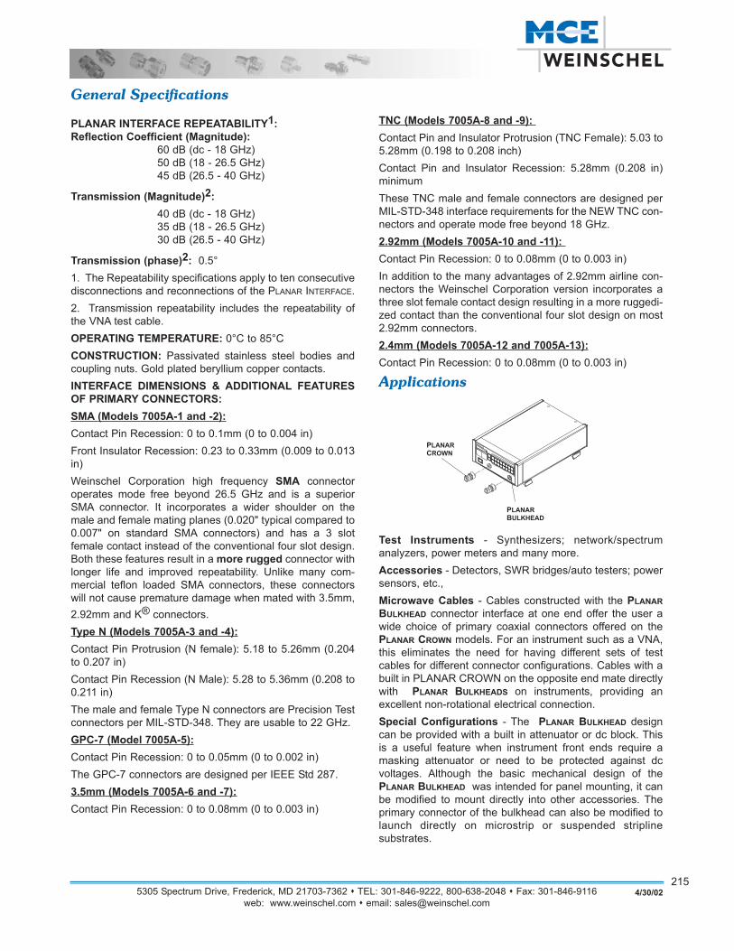
Applications
Test Instruments - Synthesizers; network/spectrum analyzers, power meters and many more.Accessories - Detectors, SWR bridges/auto testers; powersensors, etc.,Microwave Cables - Cables constructed with the PLANARBULKHEAD connector interface at one end offer the user awide choice of primary coaxial connectors offered on thePLANAR CROWN models. For an instrument such as a VNA,this eliminates the need for having different sets of testcables for different connector configurations. Cables with abuilt in PLANAR CROWN on the opposite end mate directlywith PLANAR BULKHEADS on instruments, providing an excellent non-rotational electrical connection.Special Configurations - The PLANAR BULKHEAD designcan be provided with a built in attenuator or dc block. Thisis a useful feature when instrument front ends require amasking attenuator or need to be protected against dc voltages. Although the basic mechanical design of thePLANAR BULKHEAD was intended for panel mounting, it canbe modified to mount directly into other accessories. Theprimary connector of the bulkhead can also be modified tolaunch directly on microstrip or suspended stripline substrates.
5305 Spectrum Drive, Frederick, MD 21703-7362 TEL: 301-846-9222, 800-638-2048 Fax: 301-846-9116web: www.weinschel.com email: [email protected]
2154/30/02
5305 Spectrum Drive, Frederick, MD 21703-7362 TEL: 301-846-9222, 800-638-2048 Fax: 301-846-9116web: www.weinschel.com email: [email protected]
216
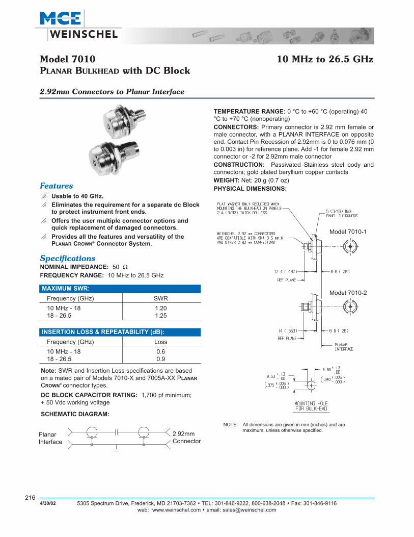
Model 7010 10 MHz to 26.5 GHzPLANAR BULKHEAD with DC Block
2.92mm Connectors to Planar Interface
NOTE: All dimensions are given in mm (inches) and are maximum, unless otherwise specified.
Featureso Usable to 40 GHz.o Eliminates the requirement for a separate dc Block
to protect instrument front ends.o Offers the user multiple connector options and
quick replacement of damaged connectors.o Provides all the features and versatility of the
PLANAR CROWN® Connector System.
SpecificationsNOMINAL IMPEDANCE: 50 ΩFREQUENCY RANGE: 10 MHz to 26.5 GHz
TEMPERATURE RANGE: 0 °C to +60 °C (operating)-40°C to +70 °C (nonoperating)CONNECTORS: Primary connector is 2.92 mm female ormale connector, with a PLANAR INTERFACE on oppositeend. Contact Pin Recession of 2.92mm is 0 to 0.076 mm (0to 0.003 in) for reference plane. Add -1 for female 2.92 mmconnector or -2 for 2.92mm male connectorCONSTRUCTION: Passivated Stainless steel body andconnectors; gold plated beryllium copper contactsWEIGHT: Net: 20 g (0.7 oz) PHYSICAL DIMENSIONS:
Note: SWR and Insertion Loss specifications are basedon a mated pair of Models 7010-X and 7005A-XX PLANARCROWN® connector types.DC BLOCK CAPACITOR RATING: 1,700 pf minimum; + 50 Vdc working voltage
SCHEMATIC DIAGRAM:
MAXIMUM SWR:Frequency (GHz) SWR10 MHz - 18 1.2018 - 26.5 1.25
INSERTION LOSS & REPEATABILITY (dB):Frequency (GHz) Loss10 MHz - 18 0.618 - 26.5 0.9
PlanarInterface
2.92mmConnector
Model 7010-1
Model 7010-2
4/30/02

5305 Spectrum Drive, Frederick, MD 21703-7362 TEL: 301-846-9222, 800-638-2048 Fax: 301-846-9116web: www.weinschel.com email: [email protected]
2174/30/02
Models 7003 & 7006 10 kHz to 18.0 GHzInside DC Block
Choice of Type N or SMA Connectors
33.84(1.38)
9.06(.38)
SCHEMATIC DIAGRAM:
FeaturesWeinschel Corporation Inside dc Block contains capaci-tance in-series with the center conductor to prevent the flowof dc current, while permitting RF power to flow withoutinterruption.o Low SWR - Maximum SWR remains low through full
frequency and power range.o Rugged Construction - Weinschel semi-precision
Type N and SMA stainless steel connectors. Moldedcaptive inner contact/bead assembly provides controlled and stable interface dimensions.
o Usable to 22 GHz.
SpecificationsNOMINAL IMPEDANCE: 50 ΩFREQUENCY RANGE: 10 kHz to 18.0 GHz
VOLTAGE RATING: + 50 Vdc maximum
CALIBRATION: Test data is available at additional cost.
CONNECTORS: Type N (Model 7003) or SMA (Model7006) connectors per MIL-STD-348 interface dimensions -mate nondestructively with MIL-C-39012 connectors.Standard unit has one male and one female connector. AddPrefix M for double male and F for double female connectors.
MAXIMUM SWR:Frequency (GHz) SWR*10 kHz - 14 1.3514 - 18 1.50
INSERTION LOSS & REPEATABILITY (dB):Frequency (GHz) Loss10 kHz - 18 0.8
* Source & load SWR of test system is <1.2.
CONSTRUCTION: Stainless steel body and connectors;gold plated beryllium copper contacts
WEIGHT: Model 7003: Net: 67 g (2.4 oz)Model 7006: Net:: 4g (0.14 oz)
PHYSICAL DIMENSIONS:
Model 7003:
Model 7006:
21(.84)
DIM "A" MAX
NOTE: All dimensions are given in mm (inches) and are maximum, unless otherwise specified.
Model # DIM A Connector Type
7003 54.61 (2.15) male-femaleF7003 50.80 (2.00) female-femaleM7003 58.67 (2.31) male-male
5305 Spectrum Drive, Frederick, MD 21703-7362 TEL: 301-846-9222, 800-638-2048 Fax: 301-846-9116web: www.weinschel.com email: [email protected]
2184/30/02
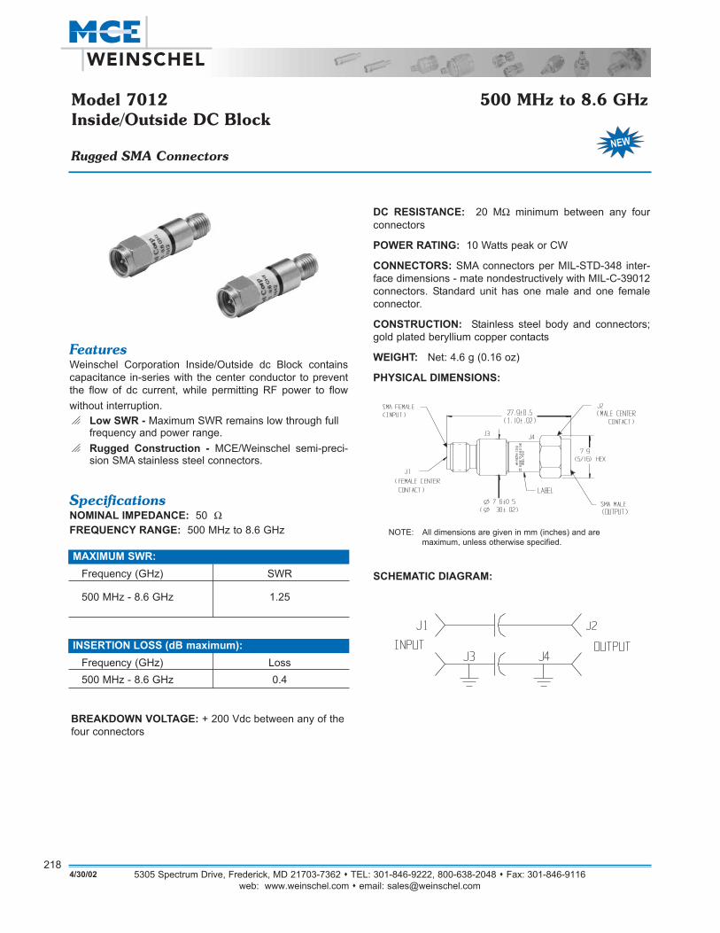
Model 7012 500 MHz to 8.6 GHzInside/Outside DC Block
Rugged SMA Connectors
SCHEMATIC DIAGRAM:
FeaturesWeinschel Corporation Inside/Outside dc Block containscapacitance in-series with the center conductor to preventthe flow of dc current, while permitting RF power to flowwithout interruption.o Low SWR - Maximum SWR remains low through full
frequency and power range.o Rugged Construction - MCE/Weinschel semi-preci-
sion SMA stainless steel connectors.
SpecificationsNOMINAL IMPEDANCE: 50 ΩFREQUENCY RANGE: 500 MHz to 8.6 GHz
BREAKDOWN VOLTAGE: + 200 Vdc between any of thefour connectors
MAXIMUM SWR:Frequency (GHz) SWR
500 MHz - 8.6 GHz 1.25
INSERTION LOSS (dB maximum):Frequency (GHz) Loss500 MHz - 8.6 GHz 0.4
DC RESISTANCE: 20 MΩ minimum between any four connectors
POWER RATING: 10 Watts peak or CW
CONNECTORS: SMA connectors per MIL-STD-348 inter-face dimensions - mate nondestructively with MIL-C-39012connectors. Standard unit has one male and one femaleconnector.
CONSTRUCTION: Stainless steel body and connectors;gold plated beryllium copper contacts
WEIGHT: Net: 4.6 g (0.16 oz)
PHYSICAL DIMENSIONS:
NOTE: All dimensions are given in mm (inches) and are maximum, unless otherwise specified.

Chandlers Way, Temple Farm Industrial Est., Southend on Sea, Essex, SS2 5SE England Tel: +44 (0)1702 463 440Fax: +44 (0)1702 463 670 web: www.dmlmicrowave.com email: [email protected]
2194/30/02
Models 7065, 7066 & 7067 100-200 WattsHigh Power Amplifiers for Intermodulation Testing
8,5 [.33]
432 [17.01]25
150,4 [5.92]
4 [.1
6]12
6 [4
.96]
19 [.
75]
57 [2
.244
]38
[1.5
0]
465 [18.31]
434 [17.90]
[19.00"]482
[5.0
0]13
3
M6 x 20 EARTH
FUSE HOLDERS
IEC 320
426 [16.77]28 [1.10]
12 [.47] TYP N TYPE (F)
N TYPE (F)
3 [.12]
40 [1.57]550 [21.65]
[.98]
SpecificationsOperating Frequency Ranges:
917 – 960 MHz (Model No. DMS 7065)1800 – 1990 MHz (Model No. DMS 7066)2110 – 2170 MHz (Model No. DMS 7067)
Small Signal Gain: 50 dB Min (52 dB typ.)Saturated Output Power: +50 dBm minNoise Figure: 10 dB maxNon Harmonics Spurious Outputs: - 60 dBc maxInput Return Loss: 17 dB minOutput Return Loss: 17 dB minSupply Voltage: 85-264 Volts AC (47-65Hz) with PowerFactor CorrectionTemperature Range: +10°C to +30°C (operating)
-25°C to +85°C (storage)Nominal RF Drive Level: 0 dBmGain Variation with Frequency: +1.0 dB max over 43 MHzGroup Delay Variation: 2.0 nS max. / 100 MHzRF Input Interface: N Type Female (Front Panel)RF output Interface: N Type Female (Front Panel)Power Consumption at rated Output: 850 Watts max(For 100W version)
General InformationThe new lower cost MCE / DML Microwave High PowerAmplifiers are specifically designed for intermodulation testing of Filters, Combiners and Connectors at 917-960MHz, 1800-1990 MHz and 2110-2170 MHZ frequencybands. The Amplifiers are available in Modular or RackMounted versions for field or production use.
Features• 100 / 150 / 200 Watt Output Power• Ideal for IMD Test Applications• High Reliability• Integral Output Protection• Rack Mounted or Modular• Integral Universal Voltage Power Supply
Physical Dimensions
Power Supply Connector: Filtered IEC 320 PlugCooling System: Integral Heatsink and FanDimensions: 19" wide, 3U Tall, Rack Mountingassembly with integral Power Supply, Fan, andOver-Temperature cut-out circuitry for Amplifiercase Temperatures of > +75°C
Notes:1. All dimension are in mm [inches] and are nominal.

5305 Spectrum Drive, Frederick, MD 21703-7362 TEL: 301-846-9222, 800-638-2048 Fax: 301-846-9116web: www.weinschel.com email: [email protected]
2204/30/02
For up to date sales & distributor listings & Information visit our website @ www.weinschel.com/rd1.cfm
US Sales Representatives....
. Berndt Associates, Inc., 1089 Third Avenue, SW, Carmel, IN46032, Tel: 317-844-0114, Fax: 317-574-9937, web: www.bai-rep.com 3115 - P North Wilke Road, Arlington Heights, IL 60004, Tel: 847-632-0900, Fax: 847-632-0993, email: [email protected] W Beloit Road, Suite 214, Milwaukee, WI 53227, Tel: 414-545-8400, Fax: 414-545-7087, email: [email protected] Winnetka Avenue, North, Minneapolis, MN 55427, Tel: 612-546-2021, Fax: 612-546-3114, email: [email protected]
. Cain-Pollock, 21874 Unbridled Avenue, Parker, CO 80134, Tel: 303-805-2515, Fax: 303-805-2514, email:[email protected]
. Cain-Sweet Co., 20595 S. W. T. V. Highway, Suite 103 B,Aloha, OR 97006, Tel: 503-591-0647, Fax: 503-591-0856, web:www.cainsweet.com, email: [email protected] 140th Place, N. E., Suite 105, Bellevue, WA 98007-3963, Tel:425-562-6028, Fax: 425-562-2680, email: [email protected]
. DFS Associates, 405 Broadmoor Road, Camillus, Ny 13031, Tel:315-487-2116, Fax: 315-488-9953, email: [email protected]
. Dynamic Technology Inc., 2013 Prairie Circle, Suite D, , Olathe,Ks 66062, Tel: 913-780-4444, Fax: 913-780-2992, web: www.dtirep.com, email: [email protected] Main Street, Highland, IL 62249, Tel: 618-651-0517, Fax: 618-651-8638, email: [email protected] E Avenue Ne, Cedar Rapids, IA 52402, Tel: 319-221-1515, Fax:319-221-1516, email: [email protected]
. E. G. Holmes & Associates, Inc., 512 E. Williams Street, Apex,NC 27502, Tel: 919-387-1072, Fax: 919-387-1077, web:www.egholmes.com, email: [email protected] Curry Ford Road, Suite 537, Orlando, FL 32812, Tel: 813-888-9218, Fax: 813-884-1764, email: [email protected]. O. Box 30, MC Minnville, TN 37111, Tel: 931-473-7155, Fax: 931-473-7216, email: [email protected] Sewell Avenue, Spring Hill, FL 34608, Tel: 352-683-6146, Fax:352-683-9896, email: [email protected]
. Electronic Distributors, Inc., 1458 Yankee Park Place,Centerville, OH 45458, Tel: 937-436-1888, Fax: 937-436-2131, email:[email protected]
. Gruber & Associates, 241 Powers Cove, GA 30067, Tel: 770-321-2495, Fax: 770-321-2497, email: [email protected]
. mmWave Technologies Inc., 315 Lonsdale Avenue, N.Vancouver, BC, V7M 2G6, Tel: 604-904-9701, Fax: 604-904-9747,web: www.mmwt.com, email: [email protected]
210 Colonnade Road, Unit #11, Nepean, Ontario, K2E 7L5, Tel: 613-224-4300, Fax: 613-224-01121868 Des Sources Blvd., Suite 404, Pointe-Claire, QC, H9R 5B1, Tel:514-426-8445, Fax: 514-426-8398Deerfoot Atrium, Unit 129, 6715 8th Street, N. E., Calgary, Alberta, T2E7H7, Tel: 403-275-9855, Fax: 403-275-36096695 Millcreek Dr., Unit # 8, Mississauga, Ontario, L5N 5R8, Tel: 905-363-1012, Fax: 905-363-1018
. R. J. Sickles Associates, 175 Bedford St., Suite 12, Lexington,MA 02420, Tel: 781-862-5100, Express: 800-Fax: 781-863-0684, web: www.rjsickles.com, email: [email protected]
. R. L. Engineering Inc.,725 Petersburg Rd, PO Box 100,Davidsonville, MD 21035, Tel: 410-760-5533, Fax: 410-798-1151, email: [email protected]
. Technical Marketing Associates, 161 Eagle Rock Avenue,Roseland, NJ 07068, Tel: 973-228-7800, Fax: 973-228-6686, web:www.tma-rf.com, email: [email protected]
. Technical Marketing Specialists, 7860 E. Berry Place, Suite110, Greenwood Village, CO 80111, Tel: 303-488-0220, Fax: 303-488-0080, web: www.tmssales.com, email: [email protected] S 48th Street, Suite 108, , Tempe, Az 85281, Tel: 480-929-0009,Fax: 480-929-0008, email: [email protected]
. The Thorson Company, 4445 Alpha Rd, Dallas, TX 75244, Tel:972-233-5744, Fax: 972- 702-0993, email: [email protected]
. Ward/Davis Associates, North, 3329 Kifer Road, Santa Clara,CA 95051, Tel: 408-245-3700, Fax: 408-738-3995, web: www.warddavis.com, email: [email protected], 2623 Manhattan Beach Blvd., Redondo Beach, CA 90278-9981, Tel: 310-643-6977, Fax: 310-643-6035
15
14
13
12
11
10
9
8
7
6
5
4
3
2
1
MCE /WeinschelCorporation
1
11
1
2
22
2
2
3
33 4
5
1
5
5
6
5
6
6
6
6
McNamara Associates, 5936 Busch Drive, Malibu, CA 90265, Tel: 310-457-4478Express #: 800-542-4457Fax: 775-261-5235email: [email protected]
99
88
10
107
11
12
15
15
13 13
14
14 14
14For states with no listing or any other questions contact Weinschel@ 301-846-9222 or 800-638-2048email: [email protected]
5

5305 Spectrum Drive, Frederick, MD 21703-7362 TEL: 301-846-9222, 800-638-2048 Fax: 301-846-9116web: www.weinschel.com email: [email protected]
2214/30/02
Worldwide Sales Representatives...Argentina: mmWave - Shikatronics S A De C V, Pringles 942, Capital Federal,Buenos Aires, CP1183, Tel: (54)11-4865-2000, Fax: (54)11-4861-7385Australia: Rohde & Schwarz (Australia) Pty., Ltd., 63 Parramatta Road,Silverwater, New South Wales, 2116, Tel: (61)2-8845-4104, Fax: (61)2-9638-3988, web: www.rohde-schwarz.com, email: [email protected] & Schwarz (Australia) Pty., Ltd., Unit 6, 2-8 South Street, Rydalmere, ,New South Wales, 2116, Tel: (61)2-8845 4100, Fax: (61)2-9638-3988Belgium: Heynen B.V., Centrum - Zuid 3047, Houthalen ( B ), 3530, Tel: (32)11-600 909, Fax: (32)11-525 777, web: www.heynen.com, email: [email protected]: Anritsu Wiltron Eletronica Ltda, Praca Amadeu Amaral, 27 Conj., 10Andar-Cj.101/102, Bela Vista, Sao Paulo, S P, 01327-010, Tel: (55)11-283-2511, Fax: (55)11-288-6940, web: www.anritsu.com, email: [email protected]: Amtest Associates, H. Belchev Str. 19, Sofia, 1000, Tel: (359)2-9800488, Fax: (359)2-9808495, email: amtestbg:mbox.cit.bgCanada: mmWave Technologies Inc., 315 Lonsdale Avenue, N. Vancouver,BC, V7M 2G6, Tel: 604-904-9701, Fax: 604-904-9747, web: www.mmwt.com,email: [email protected] Colonnade Road, Unit #11, Nepean, Ontario, K2E 7l5, Tel: 613-224-4300,Fax: 613-224-01121868 Des Sources Blvd., Suite 404, Pointe-Claire, QC, H9r 5b1,Tel: 514-426-8445, Fax: 514-426-8398Deerfoot Atrium, Unit 129, 6715 8th Street, N. E., Calgary, Alberta, T2E 7H7,Tel: 403-275-9855, Fax: 403-275-36096695 Millcreek Dr., Unit # 8, Mississauga, Ontario, L5N 5R8, Tel: 905-363-1012, Fax: 905-363-1018Chile: mmWave - Shikatronics S A De C V, M. Felix Cabrera No. 59, Ofic.203, Providencia, Santiago, , Tel: (56)2-231-1454, Fax: (56)2-231-2782China (Hong Kong): Corad Technology Ltd., Unit 1306, 13 Floor, NanyangPlaza, 57 Hung To Road, Kwun Tong, Kowloon, Tel: (852)2793-0330, Fax:(852)2793-0606, web: www.corad.com, email: [email protected]: Amtest Associates, Predstavisto Zagreb, Mikuliceva 5, Zagreb, 10000, Tel: (385)1-455-0479, Fax: (385)1-463-5222, email: [email protected] Republic: Amtest Associates, Dlouche Hony 1, Brno, 621 00, Tel:(420)5-41225215, Fax: (420)5-41225292, email: [email protected]: Compomill Nordic Components Ab, Tagtaekkervej 8, , , Odense M,Dk-5230, Tel: (45)6615-7632, Fax: (45)6615-7642, web: www.compomill.se,email: [email protected]: Shimco Engineering Consultants, No. 8 Abani Pasha Street, Zizinia,Alexandria, Tel: (20)3-5864999, Fax: (20)3-5866200, email:[email protected]: Sematron U.K. Ltd, Sandpiper House, Aviary Court, Wade Road,Basingstoke, Hampshire, RG24 8GX, Tel: (44)1256-812222, Fax: (44)1256-812666, web: www.sematron.com, email: [email protected]: Compomill Nordic Components Ab, Renbackavagen 1 C 9, , , Esbo,02750, Tel: (358)9-586-4470, Fax: (358)9-505-1832, web: www.compomill.se,email: [email protected]: B.F.I. Optilas, S.A, 4, Allee Du Cantal, Z L De La Petite MontagneSud, C E 1834, E V R Y Cedex, 91018, Tel: (33)1-6079-5900, Fax: (33)1-6079-8901, web: www.bfi.avnet.com/spain/index.html, email: [email protected]: MRC Components Gbr, Angerbrunnenstr. 12, D-85356, Freising,Tel: (498161-9848-0, Fax: (49)8161-9848-20, web: www.mrc-comp.com,email: [email protected]: American Technical Enterprises, S A, Agou Konstantinou 39, Athens,Tel: (30)1-524-0620, Fax: (30)1-524-9995, email: [email protected]: Amtest Associates, 126-128 Besci Ut, Budapest 3, Tel: (36)1436-0937, Fax: (36)1368-9642, email: [email protected]: Aimil, Ltd., Naimax House A8, Mohan Cooperative, Industrial Estate,Mathura Road, New Delhi, 110 044, Tel: (91)11-695-0001, Fax: (91)11-695-0011, email: [email protected]: Ormic Components Ltd, "Bnei-Dror" South Industrial Zone, Bldg. # 1,P.O.B. 54 Tel-Mond, 40600, Tel: (972)9-7966888, Fax: (972)3-5488660, web: www.ormic.com, email: [email protected]: Sematron Italia S.R.L., Via Mazzini 46, Trezzo Sull'adda Mi, 20056,Tel: (39)0290929158, Fax: (39)0290929166, web: www.sematronitalia.it, email: [email protected]
Japan: Seki Technotron Corp., 5-6-35, Kiba, Koto - Ku, , Tokyo, 135, Tel: (81)3-3820-1716, Fax: (81)3-3820-1733, web: www.sekitech.com, email: [email protected]: Chang Woo Inc., Keum Young Bldg., 15-11 Yeo Eui Do - Dong, YoungDeung Po - Ku, Seoul, 150-010, Tel: (82)2-782-9056, Fax: (82)2-782-9058,Email: [email protected]: MRC Components GBR, Angerbrunnenstr. 12, D-85356, Freising,Tel: (49)8161-9848-0, Fax: (49)8161-9848-20, web: www.mrc-comp.com,email: [email protected]: Test Measurement & Engineering Sdn. Bhd., 39 B, Jalan S S15/4, Subang Jaya, 47500 Petaling Jaya, Selangor Darul Ehsan, Tel: (60)3-734-1017, Fax: (60)3-734-8532, web: www.tmesystems.com.sg, email: [email protected]: Shikatronics-Mmwave S.A De C.V., Luz Saviñon No. 9-602, Col. DelValle., México, D.F, 03100, Tel: (52)5 543 7313, Fax: (52)5 543 7317, web: www.mmwt.com, email: [email protected]: Heynen B.V., De Groote Heeze 11, N L 6598 A V Heijnen,Gennep, 6590 A A, Tel: (31)485-550 909, Fax: (31)485-550 900, web: www.heynen.com, email: [email protected] Zealand: Nilsen Technologies Ltd., 1 Porters Avenue, Unit 4, AmburyCt., Eden Terrace, Auckland, Tel: (64)9-309-2464, Fax: (64)9-309-2968,email: [email protected]: Amtest-PL, 60-480 Poznan, ul.Chojnicka 57-1, Dariusz KozielloTel/fax 48 61 842 81 71, mobile 48 501 602 458, email: [email protected] Arabia: Eemco, P. O. Box 3750, 28 Baroudi Lane, Sulaymaniah,Riyadh, 11481, Tel: (966)1-477-1650, Fax: (966)1-478-5140, email: [email protected]: P.T. Tme, Blk 3014 A, Ubi Road 1, #05-12, , 408703, Tel: (65)747-7234, Fax: (65)747-7132, Web: Www.Tmesystems.Com.Sg,email: [email protected]: Amtest Associates, Halov 7, Bratislava, 851 01, Tel: (42)07-842691,Fax: (42)07-842691, email: [email protected] Africa: Measuretest C C, Unit 2, Bartlett Lake Office Park, CNRTrichardt & Dr. Vosloo Rds, Bartlett, Boksburg, Republic Of, 1459, Tel:(27)11-918-3805, Fax: (27)11-918-5176, web: www.measuretest.co.za, email: [email protected]: BFI Optilas Spain, C/ Isabel Colbrand, 6 - 4º, Madrid, 28050, Tel: (34)91-358.86.11, Fax: (34)91-358.92.71, Web: bfioptilas.avnet.com,email: [email protected]: Compomill Nordic Components Ab, Box 4, Se-194 21 Upplands,Vasby, Tel: (46)8-594 111 50, Fax: (46)8-594 211 60, web: www.compomill.se,email: [email protected]: Compomill Nordic Components Ab, Box 4, Se-194 21 Upplands,Vasby, , Tel: (46)8-594 111 50, Fax: (46)8-594 211 60, web: www.compomill.se, email: [email protected]: Schmidt Scientific Taiwan, Ltd., 6 Fl, No. 6, Alley 6, Lane 45, Pao-HsinRd, Hsin Tien, Taipei, 231, Tel: (886)2-2913-1326, Fax: (886)2-2913-1329,web: www.schmidt.com.tw, email: [email protected]: Aerocomm Company Ltd., 89 & 89\1 Intamara 41, Sutthisarn Rd.,Dindang, Bangkok, 10400, Tel: (66)2-693-8300, Fax: (66)2-693-8304, web: www.aerocommthailand.com, email: [email protected]: Türkelek Elektronik Vertriebs Gmbh, Hatay Sokak 8, TR-06650,Ankara, Tel: (90)312 418 9483, Fax: (90)312 417 5529, email: [email protected] Republic of China: Corad Technology Ltd., Room 901, KuenYang International Business Plaza, No.798, Zhao Jia Bang Road, ShanghaiPrc., 200030, Tel: (852)21-64669185, Fax: (852)21-64736398, web: www.corad.com, email: [email protected]
NOTE: For Countries NOT listed contact the Sales Department at WeinschelCorporation @ [email protected] or 301-846-9222.
*Authorized MCE/Weinschel Corporation Repair Facility. **Eastern Eroupe Countires, Alterative contact Amtest Associates, AmtestHouse, 75-79 Guildford Street, Chertsey, Surrey, KT16 9AS, England, Tel: (44)19325-68355, Fax: (44)19325-61919, email: [email protected]
For up to date sales & distributor listings & Information visit our website @ www.weinschel.com/reps.cfm
5305 Spectrum Drive, Frederick, MD 21703-7362 TEL: 301-846-9222, 800-638-2048 Fax: 301-846-9116web: www.weinschel.com email: [email protected]
2224/30/02
HOW TO ORDER: Please order by both catalog model numberand description of the component to avoid any misunderstanding(e.g., Model 1506A Broadband Coaxial Power Divider). Specialfeatures and modifications not listed in the specifications may beavailable at extra cost. Please contact the factory regarding anynonstandard features.
WHERE TO ORDER: Address all purchase orders and other communications to:
MCE / Weinschel Corporation5305 Spectrum Drive Frederick, MD 21703-7362Phone #: 301-846-9222Fax: 301-846-9116email: [email protected] Free: 800-638-2048Express: 800-542-4457 (Sickles Distribution Sales)
or contact your nearest MCE / Weinschel Sales Representative.
Purchase orders will be accepted via phone, fax or email pendingconfirmation of your standard purchase order form. Determinationof prices, terms and conditions of sale and final acceptance oforders are made only at Weinschel Corporation.
DOMESTIC TERMS: Formal price quotations remain in effect for60 days. Terms of payment are net 30 days for establishedaccounts; new accounts are also net 30 days subject to creditapproval. If credit has not been established, payment must bereceived before shipment or shipment will be made C.O.D. to avoiddelay. All prices are F.O.B. Frederick, Maryland and include com-mercial inspection and packing for shipment within the continentalUnited States.
EXPORT TERMS: Export prices including the cost of packing areavailable from MCE / Weinschel or from the export representatives.On orders placed directly with Weinschel, payment terms are Cash-in-Advance or Irrevocable Letter of Credit payable through a USBank against presentation of our draft and corresponding docu-ments. All prices are F.O.B. Frederick, Maryland.
SHIPPING INSTRUCTIONS: Unless specific instructions accom-pany the order, we shall use our judgment as to the best method ofshipment. Shipments can be made by either air or surfacetransportation.
MINIMUM BILLING: Purchase orders amounting to $250.00 net orless, will be billed at $250.00 plus shipping costs.
SOURCE INSPECTION SURCHARGE: If customer orGovernment Source inspection is required, add $100 or 2% of purchase order value, whichever is greater.
CERTIFICATE OF COMPLIANCE: A Certificate of Compliance isshipped with every order along with the packing slip. Extra copiesare available upon request at any time. The certificate states:
MCE / Weinschel certifies that all items/materials are inspectedand tested as applicable, and are in accordance with the purchaseagreement, drawings, OEM specifications, and other applicabledocumentation. Calibration and equipment standards as applica-ble are traceable to the National Institute of Standards andTechnology. Supporting documentation is on file at this facility.
WARRANTY: MCE / Weinschel Corporation warrants each productit manufactures to be free from defects in material and workman-ship under normal use and service anywhere in the world.Weinschel Corporation's only obligation under this Warranty is torepair or replace, at its plant, any product or part thereof that isreturned with transportation charges prepaid to MCE / WeinschelCorporation by the original purchaser within ONE YEAR from thedate of shipment.
Ordering & Service Information...The foregoing Warranty does not apply to, and in MCE / WeinschelCorporation's sole opinion, products that have been subject toimproper or inadequate maintenance, unauthorized modifications,misuse, or operation outside the environmental specifications forthe product.MCE / Weinschel Corporation software products are supplied with-out representation or Warranty of any kind. MCE / WeinschelCorporation, therefore, assumes no responsibility and will notaccept liability (consequential or otherwise) arising from the use ofprogram materials, disk, or tape.IN-WARRANTY REPAIRS: When returning a component back toour factory, a Return Materials Authorization (RMA) number mustbe obtained from MCE / Weinschel. When contacting us for an RMAnumber, please indicate the model number, serial number, and dateof the original purchase order. Also include as much information aspossible pertaining to nature of the malfunction or reason for return.The items returned should be accompanied with this informationand include your company name, your name, and a phone numberwhere you can be reached.OUT-OF-WARRANTY REPAIR: Should it become necessary toreturn a component for repair, follow the procedure described in thepreceding paragraph prior to shipping. Within one week afterreceipt at the factory, the unit will be evaluated and a formal quota-tion will be supplied. Repair will begin when authorization isreceived in the form of a Purchase Order. Weinschel gives a 90-daywarranty on all out-of-warranty repairs.CANCELLATION AND RETURNS: Orders placed withMCE / Weinschel may be cancelled only after authorization byWeinschel. Any authorized cancellation is subject to cancellationcharges as determined by Weinschel. A component returned forcredit will be subject to a restocking charge. If more than 6 monthshas elapsed since original purchase, the item may not be acceptedfor credit. Nonstandard components cannot be returned for credit.TEST & SERVICE: MCE / Weinschel is committed to providing fast,professional customer service and support worldwide. You have theassurance of knowing our staff of highly trained professionals isavailable using approved procedures and instrumentation.MCE/Weinschel Test and Service is always committed to quality asdefined by the customer. Full lines of repair and test services areavailable.MCE / Weinschel does not provide calibration for any product orprovide Certificates of Calibration in accordance will the require-ments of Mil-Std 45662, ISO 9001, ISO 9002, ISO 10012-1,ANSI/NCSL-Z540, or ANSI/ISO/IEC 17025-2000 requirements.MCE / Weinschel will assist our customers as following in obtainingCalibration of Product in accordance with the requirements of Mil-Std 45662, ISO 9001, ISO 9002, ISO 10012-1, ANSI/NCSL-Z540,or ANSI/ISO/IEC 17025-2000. MCE / Weinschel will provide Certificates of Conformance,Certificates of Test and Test Data Reports for products as requiredor as requested by a customer. These forms state that product hasbeen tested to published specifications using equipment whoseaccuracies are traceable to the National Institute of Standards andTechnology (NIST).
Test Data: Special and/or additional test data is available at anominal charge.Repair work: Accomplished repairs will return the item to itspublished specification. MCE/Weinschel provides a 90-daywarranty on repair services performed, with fixed price repairson most products.Telephone/E-mail Consultations: Our test and ServiceDepartment will gladly provide informal consultation over thetelephone or through e-mail ([email protected]) withtesting and or service questions.
5305 Spectrum Drive, Frederick, MD 21703-7362 TEL: 301-846-9222, 800-638-2048 Fax: 301-846-9116web: www.weinschel.com email: [email protected]
223
Alphabetical Index...Adapters, Precision . . . . . . . . . . . . . . . . . . . . . . . . . . .197-205
Frequency Asked Questions . . . . . . . . . . . . . . . . . . . . . . .200General Information . . . . . . . . . . . . . . . . . . . . . . . . . . . . .193High Performance Coaxial Adapter, N to SMA . . . . . . . . . .204Index, Precision Adapters (dc-26.5 GHz) . . . . . . . . . . . . . .198OEM Precision Coaxial Panel Mount, SMA . . . . . . . . . . . .201Precision N to N . . . . . . . . . . . . . . . . . . . . . . . . . . . . . . . .203Precision N to SMA . . . . . . . . . . . . . . . . . . . . . . . . . . . . . .205Precision SMA to SMA . . . . . . . . . . . . . . . . . . . . . . . . . . .202
Attenuators, Continuous Variable . . . . . . . . . .107, 108, 110-112General Information . . . . . . . . . . . . . . . . . . . . . . . . . . . . .108Frequency Asked Questions . . . . . . . . . . . . . . . . . . . . . . .110Index, dc to 4.2 GHz . . . . . . . . . . . . . . . . . . . . . . . . . . . . .108Precision N & SMA . . . . . . . . . . . . . . . . . . . . . . . . . . .111-112
Attenuators, Coaxial Fixed . . . . . . . . . . . . . . . . . . . . . . . .13-682.4mm . . . . . . . . . . . . . . . . . . . . . . . . . . . . . . . . . . . . . . . .332.92mm . . . . . . . . . . . . . . . . . . . . . . . . . . . . . . .31, 32, 40, 513.5mm . . . . . . . . . . . . . . . . . . . . . . . . . .30, 47, 48, 52, 53, 56 7/16 . . . . . . . . . . . . . . . . . . . . . . . . . . . . . . . . . .45, 50, 60, 66Bi-Directional . . . . . . . . . . . . . . . . . . . . .39-44, 45, 46, 50, 51BNC . . . . . . . . . . . . . . . . . . . . . . . . . . . . . . . . . . . . . . . . . .34Bulkhead . . . . . . . . . . . . . . . . . . . . . . . . . . . . . . . . . . . . . .30Calibrated Sets . . . . . . . . . . . . . . . . . . . . . . . . . . . . . . . . . .67Conductive Cooled . . . . . . . . . . . . . . . . . . . . . . . . .49, 53, 54Convection Cooled . . . . . . . . . . . . . . . . . . . .55, 57-61, 63, 65Definitions & Conditions of Attenuator
Related Parameters . . . . . . . . . . . . . . . . . . . . . . . . . . . . .68Forced Cooled . . . . . . . . . . . . . . . . . . . . . . . . . . . . . . . . . .64Frequently Ask Questions . . . . . . . . . . . . . . . . . . . . . . . .18-19General Information . . . . . . . . . . . . . . . . . . . . . . . . . . . . . .14General Purpose . . . . . . . . . . . . . . . . . . . . . . . . . . . . . .23, 35GPO™ . . . . . . . . . . . . . . . . . . . . . . . . . . . . . . . . . . . . . . . .21Hex Body . . . . . . . . . . . . . . . . . . . . . . . . . . . . . . . . . . . .22-24High Power . . . . . . . . . . . . . . . . . . . . . . . . . . .54-66, 178-180High Reliability . . . . . . . . . . . . . . . . . . . . . . . . . . . . . . .27, 31Index, dc-40 GHz, 1-5 Watts . . . . . . . . . . . . . . . . . . . . . . . .14Index, dc-26.5 GHz, 10-100 Watts . . . . . . . . . . . . . . . . . . . .15Index, dc-26.5 GHz, 150-1,000 Watts . . . . . . . . . . . . . . . . .16Index, Low IM, dc-26.5 GHz, 25-500 Watts . . . . . . . . . . . . .17Lab Standard . . . . . . . . . . . . . . . . . . . . . . . . . . . . . . . . . . .38Low IM . . . . . . . . . . . . . . . . . . . . . . .45-47, 50-52, 56, 58, 60Medium Power . . . . . . . . . . . . . . . . . . . . . . . . . . . . . . . .41-53Mil-Qualified . . . . . . . . . . . . . . . . . . . . . . . . . . . . . . . . . . . .28N . . . . . . . . . . . . . . . . . . .28, 35, 37, 38, 42-44, 46, 47, 49, 51 . . . . . . . . . . . . . . . . . . . . . . . . . . . . . . . . . . .52, 54-59, 61-66 Selection Guide . . . . . . . . . . . . . . . . . . . . . . . . . . . . . . . . .20SMA . . . . . . . . . . . . . . . . . . . . . . . . . . . . . .22-29, 39, 41, 46TNC . . . . . . . . . . . . . . . . . . . . . . . . . . . . . . . . . . . . . . .36, 53
Attenuator/Switch Controllers . . . . . . . . . . . . . . . . .166, 171-173Attenuator, Manual Step . . . . . . . . . . . . .107, 109, 110, 113-122
2.92mm . . . . . . . . . . . . . . . . . . . . . . . . . . . . . . . . . . . . . .122General Information . . . . . . . . . . . . . . . . . . . . . . . . . . . . .108Frequency Asked Questions . . . . . . . . . . . . . . . . . . . . . . .110Index, dc to 26.5 GHz . . . . . . . . . . . . . . . . . . . . . . . . . . . .109N . . . . . . . . . . . . . . . . . . . . . . . . . . . . . . . . . . . . . . . .119-121TNC . . . . . . . . . . . . . . . . . . . . . . . . . . . . . . . . . . . . . .119-121RF . . . . . . . . . . . . . . . . . . . . . . . . . . . . . . . . . . . . . . . . . . .113SMA . . . . . . . . . . . . . . . . . . . . . . . . . . . . . . . . . . . . . .113-121
Attenuators, Programmable . . . . . . . . . . . . . . . . . . . . . .127-1603.5mm . . . . . . . . . . . . . . . . . . . . . . . . . . . . . . . . . . . .152-16075 Ω . . . . . . . . . . . . . . . . . . . . . . . . . . . . . . . . . . . . . .144-147General Information . . . . . . . . . . . . . . . . . . . . . . . . . . . . .128Frequently Ask Questions . . . . . . . . . . . . . . . . . . . . . .130-131High Power, Hot Switching . . . . . . . . . . . . . . . . . . . . .178-180Index, Relay Switched, dc-2/3 GHz . . . . . . . . . . . . . . . . . .128Index, Relay Switched, dc-26.5 GHz . . . . . . . . . . . . . . . . .129
Index, Solid-State . . . . . . . . . . . . . . . . . . . . . . . . . . . . . . .129Intermodulation Distortion in Programmable
Attenuators . . . . . . . . . . . . . . . . . . . . . . . . . . . . . . . .132-134Pin Switched . . . . . . . . . . . . . . . . . . . . . . . . . . . . . . .150-151Relay Switched . . . . . . . . . . . . . . . . . . . . . .135-147, 152-160RF . . . . . . . . . . . . . . . . . . . . . . . . . . . . . . . . . . . . . . .144-147SmartStep . . . . . . . . . . . . . . . . . . .141-147, 157-160, 174-180Solid-State . . . . . . . . . . . . . . . . . . . . . . . . . . . . . . . . .148-151SMA . . . . . . . . . . . . . . . . . . . . . . . . . . . . . . . . . . . . . .135-151
Blind-Mate Connectors . . . . . . . . . . . . . . . . .197, 198, 206-2112.92mm . . . . . . . . . . . . . . . . . . . . . . . . . . . . . . . . . . . . . .209Applications . . . . . . . . . . . . . . . . . . . . . . . . . . . . . . . . . . .207Attenuators, Example . . . . . . . . . . . . . . . . . . . . . . . . . . . .210Custom Examples . . . . . . . . . . . . . . . . . . . . . . . . . . .210-211Description . . . . . . . . . . . . . . . . . . . . . . . . . . . . . . . . . . . .206Features . . . . . . . . . . . . . . . . . . . . . . . . . . . . . . . . . . . . . .206Front Locking . . . . . . . . . . . . . . . . . . . . . . . . . . . . . . . . . .209General Information . . . . . . . . . . . . . . . . . . . . . . . . . . . . .198Index, Blind-Mate Connectors . . . . . . . . . . . . . . . . . . . . . .198Frequency Asked Questions . . . . . . . . . . . . . . . . . . . . . . .200Microstrip, Example . . . . . . . . . . . . . . . . . . . . . . . . . . . . . .210Pressurized . . . . . . . . . . . . . . . . . . . . . . . . . . . . . . . . . . . .208Rear Locking . . . . . . . . . . . . . . . . . . . . . . . . . . . . . . . . . . .209SMA . . . . . . . . . . . . . . . . . . . . . . . . . . . . . . . . . . . . . . . . .208 SMB, Example . . . . . . . . . . . . . . . . . . . . . . . . . . . . . . . . .211
Calibrated Attenuator Sets . . . . . . . . . . . . . . . . . . . . . . . . . . .67Connectors, Blind-Mate & Planar Crown . . . . .197-199, 206-215DC Blocks . . . . . . . . . . . . . . . . . . . . . . . . . .197, 198, 216-218
Inside . . . . . . . . . . . . . . . . . . . . . . . . . . . . . . . . . . . . . . . .217Inside/Outside . . . . . . . . . . . . . . . . . . . . . . . . . . . . . . . . . .218Planar Bulkhead . . . . . . . . . . . . . . . . . . . . . . . . . . . . . . . .216N . . . . . . . . . . . . . . . . . . . . . . . . . . . . . . . . . . . . . . . . . . .217SMA . . . . . . . . . . . . . . . . . . . . . . . . . . . . . . . . . . . . .217, 218
Directions to Weinschel . . . . . . . . . . . . . . . . . . . . . . . . . . . .224Dividers, Power . . . . . . . . . . . . . . . . . . . . . . .183-184, 191-196Express Overnight Shipment Service . . . . . . . . . . . . . . . . . .6-7Fixed Coaxial Attenuators . . . . . . . . . . . . . . . . . . . . . . . . .13-68Manual Step Attenuators . . . . . . . . . . . . . . . .107-108, 113-122MCE Technologies, Inc. . . . . . . . . . . . . . . . . . . . . . . . . . . . .4-5MCE / Weinschel Corporation . . . . . . . . . . . . . . . . . . . . . . . .2-3Model Number Index . . . . . . . . . . . . . . . . . . . . . . . . . . . . . . .8-9New Products . . . . . . . . . . . . . . . . . . . . . . . . . . . . . . . . . . . .12OEM Programmable Attenuators . . . . . . . . . . . . . . . . .127-160Ordering & Service Information . . . . . . . . . . . . . . . . . . . . . .221Phase Shifters . . . . . . . . . . . . . . . . . . . . . . . . . . .107, 123-126
3.5mm . . . . . . . . . . . . . . . . . . . . . . . . . . . . . . . . . . . . . . .126General Information . . . . . . . . . . . . . . . . . . . . . . . . . . . . .108Index, dc to 20 GHz . . . . . . . . . . . . . . . . . . . . . . . . . . . . .108SMA . . . . . . . . . . . . . . . . . . . . . . . . . . . . . . . . . . . . . .123-125Miniature In-Line . . . . . . . . . . . . . . . . . . . . . . . . . . . . . . . .125
Planar Crown Connector System . . . . . . . . . . . . . .199, 206-209Pin Switched Programmables . . . . . . . . . . . . . . . . . . . .150-151Power Spliters & Dividers . . . . . . . . . . . . . . . . . . . . . . .183-196
2.92mm . . . . . . . . . . . . . . . . . . . . . . . . . . . . . . . . . . .190, 1953.5mm . . . . . . . . . . . . . . . . . . . . . . . . . . . . . . . .187, 189, 1944-Way . . . . . . . . . . . . . . . . . . . . . . . . . . . . . . . . . . . . . . . .196Dividers . . . . . . . . . . . . . . . . . . . . . . . . . . . . . . .183, 191-196Frequently Ask Questions . . . . . . . . . . . . . . . . . . . . . . . . .183General Information . . . . . . . . . . . . . . . . . . . . . . . . . . . . .184Index, Splitters . . . . . . . . . . . . . . . . . . . . . . . . . . . . . . . . .184Index, Dividers . . . . . . . . . . . . . . . . . . . . . . . . . . . . . . . . .184N . . . . . . . . . . . . . . . . . . . . . . . . . . . . . . . . . . . . . . . .188, 193Splitters, Matching . . . . . . . . . . . . . . . . . . . . . . . . . . .186-190SMA . . . . . . . . . . . . . . . . . . . . . . . . . . . . . . . . .184, 189, 190
4/30/02

5305 Spectrum Drive, Frederick, MD 21703-7362 TEL: 301-846-9222, 800-638-2048 Fax: 301-846-9116web: www.weinschel.com email: [email protected]
224
Product Index . . . . . . . . . . . . . . . . . . . . . . . . . . . . . . . . . .10-11Programmable Attenuators . . . . . . . . . . . . . . . . . . . . . .127-160Relay Switched Programmable Attenuators . .127-147, 152-160SmartStep Components & Subsystems . . . . . . . . . . . . .161-184
Application Specfic Subsystems . . . . . . . . . . . . . . . . .164-165Attenuator/Switch Controllers . . . . . . . . . . . . . . .166, 172-174Attenuation Modules & Multi-Channel . . . . . . . . . . . . . . . .165
SubsytemsCellular, Wireless, PCS Solutions . . . . . . . . . . . . . . . . . . .164Custom Mechanical Packaging & Modular Design . . . . . . .165Design Examples . . . . . . . . . . . . . . . . . . . . . . . . . . . .168-170General Information . . . . . . . . . . . . . . . . . . . . . . . . . .162-163Our SmartStep Approch . . . . . . . . . . . . . . . . . . . . . . . . . .167Plug & GO Switch/Relay Drivers . . . . . . . . . . . . . . . . . . . .166 The Virtual Device . . . . . . . . . . . . . . . . . . . . . . . . . . . . . . .167SmartStep Programmable Attenuator . . . . . . . . .166, 176-178Switch Matrices . . . . . . . . . . . . . . . . . . . . . . . . . . . . . . . . .164Subsystems in Minutes . . . . . . . . . . . . . . . . . . . . . . . . . . .169
Splitters, Power . . . . . . . . . . . . . . . . . . . . . . . . . .182, 185-189Solid-State Programmable Attenuators . . . . . . . . . . . . .153-154Table of Contents . . . . . . . . . . . . . . . . . . . . . . . . . . . . . . . . . .1Terminations & Loads . . . . . . . . . . . . . . . . . . . . . . . . . . .69-106
2.92mm . . . . . . . . . . . . . . . . . . . . . . . . . . . .79, 83, 88, 89, 94
3.5mm . . . . . . . . . . . . . . . . . . . . . . . . . . . . . . . .86, 90, 91, 967/16 . . . . . . . . . . . . . . . . . . . . . . . . . . . . . . . . . . . . . .92, 101BNC . . . . . . . . . . . . . . . . . . . . . . . . . . . . . . . . . . . . . . . . . .76Convection Cooled . . . . . . . . . . . . . . . . . . . . . . . . . . . .93, 96,Frequently Ask Questions . . . . . . . . . . . . . . . . . . . . . . . .74-75General Information . . . . . . . . . . . . . . . . . . . . . . . . . . . . . .70General Purpose . . . . . . . . . . . . . . . . . . . . . . . . . . . . . .76, 80GPO™ . . . . . . . . . . . . . . . . . . . . . . . . . . . . . . . . . . . . . . . .21High Power . . . . . . . . . . . . . . . . . . . . . . . . . . . . . . . . .97-106Index, dc-40 GHz, 1-10 Watts . . . . . . . . . . . . . . . . . . . . . . .70Index, dc-26.5 GHz, 25-100 Watts . . . . . . . . . . . . . . . . . . . .71Index, dc-26.5 GHz, 150-1,000 Watts . . . . . . . . . . . . . . . . .72Index, Low IM, dc-18 GHz, 25-1,000 Watts . . . . . . . . . . . . .72Lab Standard . . . . . . . . . . . . . . . . . . . . . . . . . . . . . . . . . . .77Low IM Options . . . . . . . . . . . . . . . . . . . . . .89, 90, 92, 95, 99Medium Power . . . . . . . . . . . . . . . . . . . . . . . . . . . . . . . .82-96N . . . . . . . . . . . . . . . . . . . . . . . . . . .77, 80, 81, 85-90, 93-95, . . . . . . . . . . . . . . . . . . . . . . . . . . . . . . . . . . 97-100, 102-106
Section Guide . . . . . . . . . . . . . . . . . . . . . . . . . . . . . . . . . . .73SMA . . . . . . . . . . . . . . . . . . . . . . . . . . . . . . . . .76, 78, 82, 84Subminiature . . . . . . . . . . . . . . . . . . . . . . . . . . . . . . . . .76, 78TNC . . . . . . . . . . . . . . . . . . . . . . . . . . . . . . . . . . . . . . .86, 96
US Sales Representatives . . . . . . . . . . . . . . . . . . . . . . . . . .220Worldwide Sales Representatives . . . . . . . . . . . . . . . . . . . .220
FROM DULLES/NATIONAL AIRPORTS: DULLES: Take DullesAccess Road to Capitol Beltway/Route 495. Continue to exit forRoute 270 North toward Frederick, Maryland. Travel approximately37 miles on Rt 270, and you will get off at Exit 31A--Route 85/North.Proceed to stoplight and turn right into Francis Scott Key Mallentrance. Stay in left lane, going past the mall on right, variousrestaurants on left (Pargo's, Golden Corral--caution just past herefor three-way stop signs!--continue past Pizza Hut). You are now onSpectrum Drive; you will see a cul-de-sac area with mailboxes onright; bear left into "Spectrum Plaza." Weinschel building, 5305, isto the right. Visitor parking in front of building. NATIONAL: TakeGeorge Washington Memorial Parkway North to Beltway/Rte 495.Continue on Rte 495 toward Maryland, then same as above.
FROM BALTIMORE/BWI AIRPORT: Take 195 East out of airport,to 95 North (695 Exit)*; get on 95 North and move to far left lane.Exit onto 695 North (towards Catonsville/Towson). Stay on 695Nuntil signs show 70 West/Frederick (~ 8-10 mls). Exit onto 70 West,and stay on 70W for ~55 mls; you will get off at Exit 54/MarketStreet/Rte 355. At top of exit ramp, turn right at traffic light andmerge to left lanes. Go through three traffic lights on Rte 355 South,past Wickes Lumber on left, and turn right onto New TechnologyWay. Proceed to stop sign and turn left; come to cul-de-sac and turnleft. Weinschel building, 5305, is on right. Visitor parking infront.*NOTE: Do not take 95 North (Harbor Tunnel) exit; proceed tosecond 95 North entrance.
FROM NEW YORK/NEW JERSEY: Take I-95 toward Baltimore;Exit onto Baltimore Beltway, Rt 695 West towards Towson; Exitfrom the Beltway onto I-70 toward Frederick. You will travel approx-imately 55 miles and come off at Exit 54 (Market Street). Bear rightat light coming off ramp, and quickly move over into two left lanesfor Route 355 South. Continue on Rt 355 for 1.5 miles; you will passlarge Lowes Lumber, Golden Corral, Pizza Hut, and then large redbrick Norwest building on right. Immediately thereafter is entranceto 270 Tech Park on right; follow this street to stop sign, turn left onSpectrum Drive and left again into "Spectrum Plaza." Weinschelbuilding, 5305, is to the right. Visitor parking in front.
Directions to MCE / Weinschel....
4/30/02
5305 Spectrum Drive, Frederick, Md 21703Tel: 301-846-9222, 800-638-2048Fax: 301-846-9116, Express: 800-542-4457Web: www.weinschel.comemail: [email protected]
Micro
wave &
RF C
om
po
nents & Sub
systems
MC
E/
Weinschel
02
Microwave & RF Components & Subsystems