a cfd analysis of compressible ow through convergent...
TRANSCRIPT
A CFD analysis of compressible �ow through
convergent-conical nozzles
Nathan Spotts∗, Stephen Guzik †and Xinfeng Gao‡
CFD and Propulsion Laboratory
Colorado State University, Fort Collins, Colorado, USA
Work presented at the 1st Propulsion Aerodynamics Workshop on the CFD study of
compressible �ow through convergent-conical nozzles is summarized. This work focused
on assessing the accuracy of the CFD study in obtaining nozzle performance and �ow
structure, including nozzle thrust and discharge coe�cients and the shock structure. The
CFD studies were performed using Metacomp CFD++ software and compared with the avail-
able experimental data during the workshop. We con�rmed that the discharge coe�cient
increases as the nozzle angle decreases and the choked nozzle pressure ratio is lower for
a smaller nozzle angle. The discharge coe�cient increases with increasing pressure ratio
until the choked condition is reached. The thrust coe�cient increases as the nozzle angle
increases, and for a given nozzle angle, the thrust coe�cient decreases as nozzle pressure
ratio increases. Results and assessments are presented in this paper and at the 49th AIAA
Joint Propulsion Conference.
Nomenclature
Notation
α nozzle angleCd discharge coe�cientCt thrust coe�cientγ ratio of speci�c heatsR nozzle throat radius
Subscripts, Superscripts
o quantity at the nozzle inlet∗ critical conditionsamb ambient conditionsideal quantity calculated based on
one-dimensional isentropic �owassumption
I. Introduction
The Propulsion Aerodynamics Workshop (PAW) promotes a benchmark for assessing the accuracy ofcurrent CFD technology in obtaining multi-stream air breathing jet performance and �ow structure.ThePAW also provides a forum for discussion among the the community of engineers and scientists interestedin the analysis and assessment of the aerodynamics of installed propulsion systems. We participated inthe �rst PAW and presented a CFD study of compressible �ow through convergent-conical nozzles. Theconvergent-conical nozzle type was of interest to this study because the exhaust nozzle of the jet propulsionsystem is often of convergent-conical type. Moreover, Thornock and Brown1 performed an experimentalstudy of compressible �ow through this type of nozzle, including a comparison with the theoretical analysis,in order to evaluate the e�ect of nozzle shape on the performance of convergent-conical nozzles. By varyingthe nozzle angle, they examined the nozzle shape e�ect on performance. In addition, the e�ect of nozzlepressure ratio was investigated and the value of the choked pressure ratio was determined. Therefore, PAW
∗Masters Student, Department of Mechanical Engineering, email: [email protected], Student Member.†Research Scientist, Department of Mechanical Engineering, email: [email protected], AIAA Member.‡Assistant Professor, Department of Mechanical Engineering, email: [email protected], AIAA Member.
1 of 7
American Institute of Aeronautics and Astronautics

selected the nozzle geometry and experimental data of Thornock and Brown1 as the primary reference forthe nozzle CFD study.
We performed a CFD study using the Metacomp CFD++ software.2 Through this study, we evaluatedthe accuracy of the CFD++ software and assessed the comparison between computation, experiment, andtheory. We provided our �nal CFD result to the workshop as the organizers are interested in benchmarkingthe accuracy of current CFD technology in obtaining multi-stream air breathing jet performance and �owstructure.
II. Computational Con�guration
II.A. Nozzle Geometry and Mesh
Our CFD study was conducted on axisymmetric nozzles of 15o, 25o, and 40o cone-half-angle (See Fig. 1for the cone-half-angle indicated by α), in addition to a reference nozzle (Fig. 2). The nozzle geome-try consists of a convergent truncated cone preceded by an approach section. Unlike the constant di-ameter approach section described by Thornock and Brown,1 the approach section of the computationalcon�guration has an inlet diameter of 5.7275 inches and diverges linearly to a diameter of 5.79 incheswhere the approach section meets the conical section. The diameter of the nozzle exit is 3.0 inchesfor all nozzles. The di�erence between the conical nozzles and the reference nozzle is that the latteris a convergent nozzle with a circular-arc wall contour of 5.449 inches radius. In addition, the work-shop provided a mesh for the 25o conical nozzle bifurcated by a splitter plate, in order to investigatethe e�ect of the plate on the nozzle �ow �eld. Note that the exit area is the same for all the nozzles.
Figure 1. The conical nozzle geometry with α as thecone-half-angle (15o, 25o, 40o ).
Figure 2. The reference axial nozzle geometry
According to the categorization by the PAW, the nozzlecases are grouped into three instances. Instance ¬ in-cludes four axisymmetric nozzles, i.e., the reference noz-zle and three conical nozzles with the cone-half-anglesof 15o, 25o, and 40o. The nozzle pressure ratio (NPR)range under investigation is from 1.4 to 7.0, making upeleven cases of 1.4, 1.6, 1.8, 2.0, 2.5, 3.0, 3.5, 4.0, 5.0, 6.0,and 7.0 for each axisymmetric nozzle. Nozzle pressureratio is de�ned as the ratio of nozzle total pressure atthe nozzle inlet to ambient pressure, Po/pamb. Instance consists of two cases, the 25o conical axisymmetricnozzle and the 25o conical nozzle bifurcated by the split-ter plate (Fig. 3). The objective is to compare the jetplumes resulting from them for a NPR of 4.0. Instance ® is designed to study the time-accurate simulationof vortex shedding due to the splitter plate for a NPR of 1.6. However, the mesh provided by PAW may betoo coarse to capture the vortex shedding phenomenon. For this paper, we studied the �rst two instances.
Figure 3. The 25o conical nozzle with the splitter plate.
The AIAA PAW organizers provided oversetmeshes for all calculations. The meshes for In-stance ¬ are composed of approximately 140,000hexahedral cells in four component meshes rep-resented by di�erent colors (Fig. 4). Thesemeshes comprise two angular degrees of the ax-isymmetric domain in the circumferential direction.Two cells are used in the circumferential direction, withdegenerated hexahedral cells at the axis of symmetry.The computational domain extends axially from 22.6inches upstream of the nozzle exit plane to 379.0 inchesdownstream and its extent in the radial direction is approximately 71.0 inches. Cells adjacent to the solidwall have a y+ value less than 6. The mesh used for calculations involving the splitter plate con�guration iscomposed of approximately 11×106 cells in 7 component meshes. The computational domain is half of thefull three-dimensional domain. This mesh assumes symmetry about the plane parallel to the splitter plateand coincident with its center. The extent of this mesh in the axial and radial directions is identical to theaxisymmetric mesh used for instance ¬, as is the thickness of the cells adjacent to the walls.
2 of 7
American Institute of Aeronautics and Astronautics

II.B. Numerical Setups
Figure 4. A typical overset mesh created by PAW and used inthe simulations.
The working �uid is air and treated as an idealgas. The nozzles discharge directly into the at-mospheric conditions. Boundary conditions arespeci�ed for the inlet, outlets, and solid nozzlewalls. At the nozzle inlet, total pressure andtotal temperature are speci�ed. At the outlet,a back pressure is speci�ed. No-slip boundaryconditions are applied to the nozzle walls. Thethermal wall conditions, both isothermal (atmo-spheric temperature) and adiabatic, were exam-ined and no signi�cant di�erences were found.
The CFD solver utilized for this study wasCFD++ from Metacomp Technologies.2 Thecompressible, steady-state, Reynolds-averaged,Navier-Stokes equations were solved using a density-based algorithm. The algorithm is based on the �nite-volume method with a second-order accuracy in space. A total variation diminishing scheme was employed.A min-mod limiter was adopted for cases of NPR less than 2.0 and a continuous limiter was used for othercases. For nozzle pressure ratios greater than 1.8, minimum dissipation was added by a pressure switch to theright hand side in areas were pressure variations were not smooth. The time integration scheme is implicitand second order accurate. Three turbulence models, the realizable k-ε, the Menter shear stress transport,and the realizable q-L model were employed, and they had little impact on both the �ow properties of interestand the �ow structure (particularly the location of the sonic line).
III. Simulation Results and Analysis
The nozzle performance is evaluated by the nozzle thrust coe�cient, Cv, and the discharge coe�cient,Cd. For the 2D axisymmetric nozzle, they are de�ned by
Cv ≡∫ R0[ρu2 + (p− pamb)]rdr
Uideal
∫ R0ρurdr
and Cd ≡2π∫ R0ρurdr
mideal,
where ρ, u, and p are local density, axial velocity, and pressure, respectively on the integration path. Theradius and area at the nozzle exit are denoted by R and Athroat, respectively. The subscript, �ideal�, refers toquantities calculated for an ideal nozzle based on one-dimensional isentropic �ow assumption. The isentropicmass �ow rate, mideal, is calculated by3
mideal =ΨPoAthroat√
(γRTo), Ψ ≡
{2γ2
γ−1pthroatPo
[1− (pthroatPo)(γ−1)/γ ] pthroat < p?
γ( 2γ+1 )
(γ+1)/(2(γ−1)) pthroat ≥ p?
where Ψ is the �ow factor, pthroat is the static pressure at the nozzle throat, p? the critical pressure,3 γthe speci�c heat ratio, R the universal gas constant, and Po and To are stagnation conditions. They aredetermined by Po = p(1+ γ−1
2 M2)γ/(γ−1) and To = T (1+ γ−12 M2), respectively; M is the local Mach number
and T is the local static temperature. The ideal velocity, Uideal, based on an ideal convergent-divergent nozzle
operating at the same pressure ratio, is computed by Uideal =
√2γRTγ−1
(1− (pthroatPo
)(γ−1)/γ). Using above
relations, we calculated both the nozzle thrust coe�cient and the discharge coe�cient for all the cases in theinstance ¬. What follows are the comparisons between the CFD results and the experimental and analyticalresults published by Thornock and Brown1
III.A. Numerical Results
Forty-four simulation cases were solved for instance ¬. We determined the e�ect of the nozzle pressureratios on the thrust and discharge coe�cients, as well as the in�uence of the nozzle angles. In addition, weevaluated the CFD++ software performance for nozzle studies. Herein, we illustrate some simulation results
3 of 7
American Institute of Aeronautics and Astronautics

using the Mach contours for the 25o nozzle. Results for the complete set of instance ¬ are analyzed andpresented in the next section, and they are compared with the literature data.
(a) 1.4
(b) 2.0
(c) 3.0
(d) 3.5
(e) 4.0
(f) 5.0
(g) 6.0
(h) 7.0
Figure 5. Mach contours for α = 40o with NPR = 1.4�7.0.
Figures 5(a)�5(h) show the Mach contour for the25o-nozzle with NPRs from 1.4 to 7.0. Both theaxial and the radial coordinates are normalized bythe the radius at the nozzle exit. We clearly ob-serve, from Fig. 5(a)�5(h), that the �ow �eld in thethroat of the nozzle is nonuniform and the positionof the sonic line becomes independent as NPR in-creases beyond the choked value. For this case, itdoes not change signi�cantly for NPR greater than4.0. The shape of the discharging jet depends onNPR.The observations are as expected and consistentwith those in literature.1,3 Increasing the NPR(by raising the inlet pressure) results in the prop-agation of a rarefaction wave from downstream ofthe nozzle towards the nozzle with a wave speedof the absolute local sonic speed. This causes anincrease in the mass �ow rate. However, whenthe pressure ratio is equal to or greater than thechoked pressure ratio, the wave or the distur-bances from the downstream of the nozzle can nolonger be propagated upstream and the mass �owrate stays unchanged.The jet issues as a cylindrical-like stream, asshown in Fig. 5(a) and 5(b). Under the chokedconditions, the jet leaving the nozzle is at thechoked pressure, which is higher than the backpressure. The underexpanded �ow results in anexpansion at the nozzle exit. Boundary conditionsof ambient pressure at the top and no penetrationat the centerline force an alternating pattern ofre�ecting compression/shock and expansion fans.The curved sonic line resulting from the non-uniformity of the �ow at the nozzle exit is clearlyshown in Fig. 6 for a 40o nozzle at a NPR = 4.0,which is slightly upstream of the nozzle exit planenear the nozzle lip and considerably downstreamof the exit plane near the centerline.
Figure 6. Lines of Mach number for α = 40o at a NPR= 4.0
4 of 7
American Institute of Aeronautics and Astronautics

(a) reference nozzle
(b) α = 15o
(c) α = 25o
(d) α = 40o
Figure 7. Mach contours for the axisymmetric nozzles at NPR = 7.0.
From Fig. 5, one can observe theMach disk in the downstream of thenozzle for the cases under supercriti-cal conditions. As NPR increases, theMach disk moves farther downstreamand the radius of the Mach disk in-creases.4 The Mach disk is a conse-quence of satisfying mass �ow rate andturning angle constraints that are notachievable with oblique waves. Thenozzle angle has little e�ect on boththe location and the radius of the Machdisk, as shown in Fig. 7 for a NPR of7.0.
The instance includes two simula-tion cases. The diamond shock struc-ture resolved from the CFD result forthe 25o axisymmetric nozzle is clearlyshown in Fig. 8(a). The contour of the|∇ρ| �eld for the con�guration with thesplitter plate is displayed on the tophalf of the Fig. 8(b) in contrast withthe bottom half showing the |∇ρ| con-tour for the axisymmetric nozzle.3
(a) The |∇ρ| �eld for the con�guration without splitter plate showing �diamond� shock structure
(b) Comparison between the |∇ρ| �elds, top: with splitter plate and bottom: without the splitter plate
Figure 8. The comparison between the numerical �ow structures for instance.
With the splitter plate, the shock location (the intersection between the shock and the axial axis) ismoved toward the nozzle and the angle between the shock and the axial axis is smaller. Since the �ow issupersonic between the nozzle exit and the shock, features downstream do not in�uence the �ow in thisregime. Consequently, the shock location is likely a result of the reduced e�ective nozzle exit area, perhapsdue to boundary layer associated with the splitter plate. Behind the shock, the �ow is subsonic and someinformation can propagate to and a�ect the shock. The decreased angle is perhaps a result of the plateterminating and small cavity behind it. In summary, the e�ect of the plate is probably better quanti�ed by
5 of 7
American Institute of Aeronautics and Astronautics

the location of the shock rather than the angle.
III.B. Comparison with Experimental and Analytical Data
We compare the nozzle discharge coe�cient and the thrust coe�cient predicted from the CFD results tothat measured by experiments and the analytical solution. Figure 9(a) shows that, for a given nozzle angle,the discharge coe�cient increases with increasing nozzle pressure ratio until the choked condition is reachedand, for a given nozzle pressure ratio, the discharge coe�cient increases as the nozzle angle decreases. Thechoked nozzle pressure ratio is smaller for a smaller nozzle angle. Overall, the discharge coe�cient based onthe CFD result is over-predicted in comparison to both the experimental and analytical data.
(a) Discharge coe�cient (b) Thrust coe�cient
(c) The sonic lines, NPR= 2.5 (d) The sonic lines, α = 25o-nozzle
Figure 9. Comparison of the numerical results to the experimental and analytical data. Sub�gure 9(a) compares thedischarge coe�cients and shows the nozzle angle e�ect on the discharge coe�cients. Sub�gure 9(b) compares the thrustcoe�cients and shows the nozzle angle e�ect on the discharge coe�cients. Sub�gure 9(c) compares the sonic lines andshows the nozzle angle e�ect on the location of the sonic lines. Sub�gure 9(a) compares the sonic lines and shows thenozzle pressure ratio e�ect on the location of sonic lines.
We believe that the source for this discrepancy is due to the non-conservative mass predicted for theoverset mesh. The mass imbalance between the predicted in�ow and out�ow mass, approximately 1∼2%,may result from the technique used in treating the overset grids. The nozzle coe�cient is sensitive to thislevel of mass imbalance. Using overlapping grids appears not to be a good choice in cases where conservation
6 of 7
American Institute of Aeronautics and Astronautics
is paramount. Although in this study, we used only meshes provided, in practice, an non-overlapping meshmay yield better results. Figure 9(b) shows the thrust coe�cient computed for the 15o, 25o and 40o nozzles,
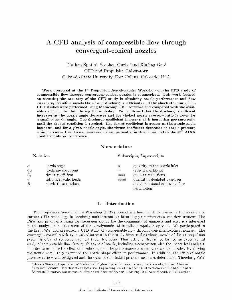
(a) without splitter plate, top: CFD simulation and bot-tom: experimental data
(b) with splitter plate, top: CFD simulation and bottom:experimental data
Figure 10. The comparison between the numerical and experimental shock structures for the instance.
as well as that for the reference nozzle, in comparison to the experimental data and the theoretical result.The reference nozzle exhibits a lower value of thrust coe�cient than those of the conical nozzles. The thrustcoe�cient increases as the nozzle angle increases. For a given nozzle angle, the thrust coe�cient decreases asNPR increases. The thrust coe�cient based on the CFD results is in general higher than the experimentaland the discrepancy increases with increasing NPR, likely due to the non-conservative issue associated withthe overset grids. In Fig. 9(c), we plot the sonic lines at the throat of the three axisymmetric nozzles with thesame pressure ratio of 2.5, and for each nozzle the agreement between the CFD, experimental, and theoreticalis good. The sonic line is curved, and the curvature increases with increasing the nozzle angle. The sonicline is carried farther downstream for the higher nozzle angle. We also examined the NPR e�ect on the sonicline location and found that the sonic line is moved to the throat with increasing pressure ratio, as seen inFig. 9(d) for a 25o nozzle. The CFD result agrees well with the experimental data. However, for the caseof NPR = 2.0, both computational and experimental data deviate from the theoretical data. Figures 10(a)and 10(b) compare the predicted shock structure to the experimental shadowgraphs for the axisymmetricnozzle and the nozzle bifurcated with the splitter plate, respectively. The predicted shock locations for bothcases are in excellent agreement with the experimental results.
IV. Concluding Remarks and Future Work
We performed a CFD study of the compressible �ow through convergent-conical nozzles to investigatethe e�ect of the nozzle pressure ratio and nozzle angle on the nozzle performance. We con�rmed that thedischarge coe�cient increases as the nozzle angle decreases and the choked nozzle pressure ratio is lower fora smaller nozzle angle. The discharge coe�cient increases with increasing pressure ratio until the chokedcondition is reached. The thrust coe�cient increases as the nozzle angle increases, and for a given nozzleangle, the thrust coe�cient decreases as nozzle pressure ratio increases. The results predicted by the CFD++software generally are consistent with the literature data. However, our discharge coe�cient is overpredicted,and this is likely due to the nonconservative mass predicted for the overlapping mesh. Future study includesinvestigation of the algorithm techniques for enforcing conservation using a non-overlapping mesh.
V. Acknowledgments
The simulations were performed on the Colorado State University ISTeC HPC System supported by NSFGrant CNS-0923386. We thank the Metacomp Technologies, Inc. for their strong support of CFD++ softwareand many useful discussions.
References
1Thornock, R. L. and Brown, E. F., �An Experimental Study of Compressible Flow Through Convergent-Conical Nozzles,Including a Comparison With Theoretical Results,� Journal of Basic Engineering, Vol. 94, No. 4, 1972, pp. 926�930.
2�Metacomp Technologies,� http://www.metacomptech.com/.3Zucrow, M. J. and Ho�man, J. D., Gas Dynamics, Wiley, 1976.4Chang, L. and Chow, W., �Mach disk from underexpanded axisymmetric nozzle �ow,� AIAA Journal , Vol. 12, No. 8,
1974, pp. 1079�1082.
7 of 7
American Institute of Aeronautics and Astronautics