a conceptual framework for computer architecture* · fers from yon neumann architecture in...
TRANSCRIPT

A Conceptual Framework for Computer Architecture*
S.S. REDDI
W. W. Gaertner Research, Inc., 1492 High Ridge Road, Stamford, Connecticut 06908
E.A. FEUSTEL
Laboratory for Computer Science and Engineering, Department of Electrical Engineering, Rice University, Houston, Texas 77005
The purpose of this paper is to describe the concepts, definitions, and ideas of computer architecture and to suggest that architecture can be viewed as composed of three components: physical organization; control and flow of information; and representation, interpretation and transformation of information. This framework can accommodate diverse architectural concepts such as array processing, mieroprogramming, stack processing and tagged architecture. Architectures of some existing machines are considered and methods of associating architectural concepts with the components are established. Architecture design problems and trade-offs are discussed in terms of the proposed framework.
Keywords and Phrases: computer architecture, framework, composition of architecture, information flow, physical organization, unification of diverse architectural concepts.
CR Categories: 6.0, 6.20, 6.22, 6.29.
INTRODUCTION
Computer architecture is receiving, and will continue to receive special attention as novel architectures differing from the classic von Neumann organization emerge as viable approaches to the problem of increasing the computational speeds and cost-effectiveness of computer systems. Computers such as the CDC 6600, CDC STAR-100, TI ASC, Burroughs B6700, Goodyear STARAN and CRAY-1 are con- vincing arguments that architecture plays a prominent role in deciding computer system performance and in achieving faster computational speeds than has been pre-
* This work was supported by NSF" Grant GJ 36471, and was performed while the first author was at Rice University.
viously possible. In the literature there is a multitude of proposals as to how computer architecture can be defined and how an architect's job can be described. Unfortu- nately, most of these proposed concepts touch only different facets of computer architecture and do not encompass the complete spectrum of architectures. In this paper we present a conceptual viewpoint that allows a coherent and unified treatment of computer architecture. We believe that computer architecture can be viewed as composed of 1)physical organization; 2) control and flow of information; and 3) representation, interpretation and trans- formation of information, and we develop a framework for architecture based on this viewpoint. We consider some existing com-
Copyright © 1976, Association for Computing Machinery, Inc. General permission to republish, but not for profit, all or part of this material is granted provided that ACM's copyright notice is given and that reference is made to the publication, to its date of issue, and to the fact that reprinting privileges were granted by permission of the Association for Computing Machinery.
Computing Surveys, Vol. 8, No. 2, June 1976

278 • S. S. Reddi and E. A. Feus~l
CONTENTS
INTRODUCTION EXISTING DEFINITIONS AND INTERPRETATIONS OF COMPUTER ARCHITECTURE FRAMEWORK FOR COMPUTER ARCHITECTURE SOME EXISTING COMPUTER ARCHITECTURES
Phye/cal Organization CONTROL AND FLOW OF INFORMATION
Procemor Organization Stack Mechanism
Repreeentation, Interpretation and Transformation of Information
Representation and Interpretation of Instructions Representation and Interpretation of Data Transformation (or Dynamic Representation) of Information
Physical Organization and Control of Information Flow Basic CPU Organization I/O Handling Memory Organization
Physical Organization, Control of Information Flow and Representation and Interpretation of Information
ARCHITECTURAL CONCEPTS AND CONSIDERATIONS
Array Orgamzation Pipeline Orgamzation Modular Organization Stack Proce~ing Virtual Memory Virtual Machines Parallel ProceMing Tagging of Information Emulation Developing an Architecture Dynamic Architectures
REFERENCES
puter architectures and show how to associ- ate architectural concepts and innovations with these three components. We then develop architectural concepts that a system architect can use and verify that these con- cepts can be accommodated within our framework. Finally, we indicate how our hypothesis can lead to the concept of dy- namic system architecture.
EXISTING DEFINITIONS AND INTERPRETATIONS OF COMPUTER ARCHITECTURE
We first consider the various definitions and interpretations of a computer architect's job and of computer architecture as pre- sented in the literature. According to Brooks [8]: "The computer architect designs the external specifications, gross data flow, and gross sequencing of a system. He is, like the building architect, the user's advocate. He must balance the conflicting demands of engineer (cost, speed), programmer (func- tion, ease of use) and marketing (function, speed, cost) to yield the machine of greatest true value to the user . . . . " Foster in Com- puter architecture [17] introduces the archi- tect as follows: "The computer architect in turn is unconcerned with the insides of an adder or a shift register. His job is to as- semble the units turned out by the logical designer into a useful, flexible tool that is called a computer." Beizer [6] describes the architect's job as " . . . the design of a hard- ware/software complex, subject to realistic technical, economic, operational and social constraints such that it 1) works, 2) is opti- mum and 3) survives." He summarizes the architect's role by stating that "it is syn- thetical, catalytic and translative. His de- sign is a synthesis of the substances of sub- ordinate disciplines." Abrams and Stein [1] explain the architect's duties: "The job of the computer system architect is to de- velop an overall concept of a machine--what it can do and how that solves the problem for which the machine is intended. Just as an architect who designs houses must consider utility, appearance, and compatibility with the neighborhood, so must the computer designer balance requirements, user inter- face, and costs to make a viable design."
Several explicit definitions of architecture also can be found. The term "Architecture" is used by Amdahl, et el., [2] in introducing the IBM System/360 "to describe the at- tributes of a system as seen by the pro- grammer, i.e., the conceptual structure and functional behavior, as distinct from the organization of the data flow and controls, the logical design, and the physical imple- mentation." Foster [17] explains: "The field
Computing Survey¢, VoL 8, No. 2, June 1976

A Conceptual Framework for Computer Architecture • 279
of computer architecture, or 'the art of de- signing a machine that will be a pleasure to work with' is only gradually receiving the recognition it deserves. This art, one can- not call it a science, is one step more ab- stract than that of a logical designer, which in turn is abstracted from the study of elec- tronic circuits." Finally Foster [16] also suggests: "Computer Architecture is the profession of adopting present day tech- nology to the solution of current computing problems and of dreaming about the future of the field in such a way as to influence it for the better."
A FRAMEWORK FOR COMPUTER ARCHITECTURE
The disparities in existing definitions and interpretations of computer architecture are directly traceable to its multifaceted nature. Since computer architecture can be viewed from different perspectives, each individual forms his own notion and interpretation. A FORTRAN user may not perceive signifi- cant architectural differences between IBM and CDC computers other than word and core size. On the other hand a system pro- grammer can easily distinguish the archi- tectures of these computers in terms of their operation codes, address formation, and input/output. However, he will find it diffi- cult to distinguish an IBM 370/125 from an IBM 370/155, or a CDC 6600 from a CDC 7600, and will be unable to perceive hard- ware parallelism that may exist in the central processing unit. Thus architectural details can be transparent or visible depending on the viewer and his level of perception.
Our hypothesis is conditioned by the above observations, as we compare and con- trast architectures and architectural features in terms of the following three components. For a valid comparison we should choose commensurate levels, i.e., user level, system programmer level.
1) Physical organization; 2) control and flow of information; and 3) representation, interpretation and
transformation of information. Let us consider some examples. The
ILLIAC IV and a conventional von Neumann
organization have different architectures; they differ in their physical organization and the way they handle control and flow of information. Tagged architecture [12] dif- fers from yon Neumann architecture in representation and interpretation of informa- tion. The term "transformation" in the third component refers to the situation where representation and interpretation of information are changed dynamically by the system for user convenience, system efficiency, or for implementing a software system to support privacy and protection. This kind of transformation is to be dis- tinguished from the algorithmic transfor- mation on data undertaken in solving spe- cific problems.
SOME EXISTING COMPUTER ARCHITECTURES
In this section we consider some existing computer systems and explain their archi- tectural features using our three components. These explanations are sufficiently detailed so that the reader may become familiar with the process of associating architectural concepts with the components. In addition we consider microprogramming, an estab- lished architectural feature, to reinforce our arguments regarding the validity of our hypothesis.
Physical Organization
Technological advances achieved in the past decade enabled architects to propose many innovative physical organizations for com- puter systems, some of which have already been realized in practice. Three computer systems, the CDC 6600, ILLIAC IV and TI ASC, are studied to show the different organizations that can be conceived. The CDC 6600 is an example of distributed computing and employs an organization which exploits functional parallelism. The ILLI•C IV and TI ASC use array and pipe- line organizations respectively for enhanced performance. All three systems depart from the conventional yon Neumann machine in their physical system organization.
CDC 6600 Central Processor Organization: The CDC 6600 [32] organization shown in Figure 1 has ten independent functional
Computing Surveys, Vol. 8. No, 2, June 1976

280 • S. S. Reddi and E. A. Feustel
PPO I
EXTERNAL PP3 1 PERIPHERAL ,m.-m
EQUIPMENT CHANNELS
,
ppcj J |
PERIPHEI PROCESSq
18-BIT ADDRESS REGISTERS
INPUT REGISTER
60-BIT INSTRUCTION STACK
I6 I5 I4
I2 I1
I 4 I
18-B IT INDEX REGISTERS
P REGISTER
I I
I0 FUNCTIONAL UNITS
ADD MULTIPLY MULTIPLY DIVIDE FIXED ADD INCREMENT INCREMENT BOOLEAN SHIFT ---I,, BRANCH
T J SCOREBOARD
INSTRUCTION REGISTERS
Figure 1. Block diagram of the CDC 6600 computer system, an example of distributed computing architecture.
units, twenty-four data and address registers, an instruction stack and a scoreboard in its central processor. The ten functional units, which are independent of each other, are capable of simultaneous operation. The functional units are specialized to perform operations such as floating add, floating multiply, floating divide, shift, fixed add, etc. The twenty-four registers are divided into data (X~), address (A,) and index (B~) groups; each group consists of eight registers. Except for data registers which are sixty bits long, all registers are eighteen bits long. Data registers XI through X5 are used as "read" registers and X6 and X7 as "store" registers. There is a "partner" re- lationship between X, and A~ registers. An operand is fetched into X~, i = 1 to 5, from memory by loading its addresses into A,; similarly an operand is stored from X~,
i = 6, 7, into the memory location specified by A,. The index registers used are to modify the addresses in the address registers. (For instance, there is an instruction which adds As and Bk and transfers the result to A,). The index registers are also used to store fixed-point integers and manipulate float- ing-point exponents. Registers Ao and Xo are used to reference the extended core storage. The partner relationship permits concurrent calculation of arithmetic and address information. All arithmetic compu- tations are performed on operands from the twenty-four registers with results returned to these registers.
Instructions are loaded into the processing unit under the control of P register (see Figure 1). The instruction stack contains eight 60-bit registers capable of holding up to 32 instructions. Instructions are ae-
Computing Surveys, Vol. 8. No. 2, June 1976

A Conceptual Framework for Computer Architecture • 281
cessed from memory and stored in a last in, first out (LIFO) manner in the instruction stack. When the program executes a branch to one of the instructions stored in the stack, that instruction is directly fetched from the stack rather than from memory. In this way it is possible to cut down the number of memory accesses in the case of loops that can be accommodated in the stack. Instructions pass from the instruc- tion stack to three instruction registers U0, U1 and U2 whose contents are interpreted and decoded by the scoreboard. The score- board examines the instruction to be exe- cuted and determines whether the func- tional unit and registers needed for the execu- tion of the instruction are available; if they are available the instruction is initiated. Otherwise, the instruction is held until they are available. The scoreboard main- tains the status of each central register and functional unit so that it can decide when an instruction can be issued. The score- board provides interlocks between instruc- tions so that though parallelism in instruc- tions is exploited, precedences among in- structions as specified by the programmer are still preserved.
The ILLIAC IV System: This system [5] employs an array structure for organizing its processors. It consists of 256 processing elements arranged into four quadrants. Only one quadrant has been constructed because of economic considerations.
A quadrant consists of a control unit and sixty four processing elements. Processing element i is connected to processing elements i W 1 (mod 64), i - 1 (mod 64), i -~ 8 (mod 64) and i - 8 (mod 64). The control unit fetches instructions from a processing ele- ment memory, decodes them, and issues control pulses to the processing elements for execution. I t broadcasts memory ad- dresses and data words when they are common to all processors. An instruction can be either a control or processing unit instruction. The former directs operations local to the control unit whereas the latter controls the execution of the processing units. The control unit is designed to over- lap the executions of the two different in- struction types.
The processing element consists of the processing element memory (2048 64-bit words), arithmetic and logic circuitry, and registers. Each element executes the common instruction issued by the control unit on data stored in its memory. An element will not execute the common instruction if its enableflip-flop is not set. In other words all the enabled elements execute the same in- struction issued by the control unit. Digital Equipment PDP-10 computers perform the executive control of system operation, I /O processing and supervision, and compilation of the ILLIAC IV programs.
The TI ASC System: A principal feature of the Texas Instruments Advanced Scien- tiiic Computer (ASC) [31] is the central processor's four pipelines (Figure 2). If computational requirements do not warrant the capacity of four pipelined arithmetic units, one or two pipeline CPs are available. The CP pipeline consists of the instruction processing unit (IPU), the memory buffer unit (MBU), and the arithmetic unit (AU). The IPU supplies a continuous stream of in- structions for execution by the other units of the pipeline. I t fetches and decodes in- structions, accesses and stores operands, and handles branch conditions. The MBU pro- vides an interface between the central mem- ory and AU by supplying a continuous stream of operands to the AU and storing results in the memory. The AU performs arithmetic operations and is pipelined as shown in Figure 2. Depending on the mode of arithmetic operation, the pipeline is struc- t~ured to divert operand flow along the dot- ted or solid lines. The central processor is a vector as well as scalar processor and has vector instructions at machine level.
CONTROL AND FLOW OF INFORMATION
Information flow and its control in a com- puter play a prominent role in deciding the computer architecture. This component en- compasses the aspects of control mechanisms and schemes used for controling and direct- ing the system's information flow. Note the interdependence between the control and flow elements. Sometimes control initiates information flow (as in conventional syn-
Computing Surveys, Vol. 8, No. 2, June 1976

PRIMARY f MEMORY PORTS
I
J J I I
282 • S. S. Reddi and E. A. Feus~l
I--
PRIMARY f MEMORY PORTS
_I
FOUR--RIPFLINE CP ASC 4X
L- TWO--PIPELINE CP
ASCZX
FLOATING ADO FIXED MULT
RECEIVER REGISTER
L . . . .
EXPONENT SUBTRACT
ALIGN
t t +
[ j
J
I ACCUMULATE
RESULT RESULT
Figure 2. Processing and arithmetic pipelines of the TI/ASC system. (Reprinted, by permission of Texas Instruments Inc., from A description of the advanced scientific computer system).
chronous computers where control pulses are issued periodically to direct information flow) and sometimes information flow initi- ates control (as in interrupt and data driven schemes); thus the control element may be isolated from or incorporated in information flow. Control may be centralized (as in most computer systems) or decentralized (as in a network of microprocessors).
Alteration of information flow in a tradi- tional computer leads to novel and interest- ing architectures. A familiar example is the Burroughs B6700, a stack processor. In the following we describe briefly the B6700 processor and stack organization and indi- cate how information flow is affected by the stack.
The Burroughs B6700: An integrated hardware-software approach is taken in
designing the B6700. The system is pro- grammed using high level languages (e.g., ALGOL, COBOL and FORTRAN) and does not offer the user a traditional machine level language. The system hardware is designed to handle block structured languages and procedures efficiently by means of a stack mechanism and display registers. One learns to appreciate the system architecture more when one becomes familiar with the aspects of system implementation associated with block structured languages, such as access- ing global and local variables, address for- mation for accessing procedure segments, and nesting of blocks.
Processor O r g a n i z a t i o n
A block diagram of the processor [10] is shown in Figure 3 [11]. A program word is
Comput ing SurveyB, Vol. 8, No. 2, June 1976

A Conceptual Framework for Compub~r Architecture • 283
ARITNMETI¢ CONTROLLER
1 , | |
ARIThmETIC LOGICAL OPS OPS
| OPERATOR DEI~ENOENT INTERRUPTS
,,X/z .U.
PROGRAM CONIROLLER (SYLLAIL[ DECOOE)
~L ~10 mJS I I l
SU| ROUTINE JWORD ORIENTEDJ SCALING O,S 1 OPS I OPS
I ! ! ,~21I ll(JS
STACK ADJUST
CONTROLLER
|
I I FAMILY J VALUE CALL
OP
I
I STRING 1 OffERATOR
CONTROtLER
NAME CALl. OP
I
INTERRU~S CONTROLLER INTERRUPTS
TRANSFER CONTROLLER J INTERNAL [ ~ TRANSTER ~ /
INPUT ~ OUTPUf
Mf MORY INFO J •
FROM CONTROLLERS AND FAMILY OPS
J r . . . . fOR , / o PRC~
I
-I PROG~ SEGMENT
A
PROGRAM WORD . . . n
PROGRAM WORD 3
PROGRAM WORD 2
PROGRAM WORD !
PROGRAM WORD o "
Io I, 12 I~ I. I, I I "P" REGISTER
L l l l L l
W
f I I
- - J
J PROGRAM tNOIEX REGISTER / I-
- - - - - - - ~ PROGRAM ~ ~GISTER J
I
ADDER
P S R ]
W OPERATOR F A M I L Y " T " REGISTERS
Figure 3. A functional diagram of the Burroughs B6700, a stack processor. (Reprinted, by permission of Burroughs Corporation, from The B6700 iuformat,~t referenc~ manual I0586~).
Computing Surveys, Vol, 8, No. 2, June 1976

284 • S. S. Reddi and E. A. Feustel
transferred to the P register through the memory controler under the control of the program controler. The program controler examines the instruction to be executed and initiates the proper operator family. Re- lated operators are grouped into a single operator family; thus family A performs all arithmetic operations, family B performs all logic operations, and so on. The arith- metic and string controlers are enabled by their respective family operators; they con- trol and supervise the execution of arith- metic and string operations.
The transfer controler contains registers A, X, B and Y necessary for setting up the stack. The interrupt controler provides a method of interrupting the program flow'by setting up necessary control words in the stack. The processor takes the appropriate action by examining the control words. The memory controler handles storage re- quests and contains an adder which is used to generate addresses. The stack controler is responsible for automatic stack adjust- ment; it manipulates data between main memory and the A and B registers during the pop-up and push-down operations of the stack.
The machine language operators are composed of eight-bit syllables and each memory word consists of six syllables. The operator syllable pointed to by the program syllable register is decoded, and the operator family specified by the operator syllable is selected to receive the execute signal. The T register in each family specifies the opera- tion to be performed in that particular family.
Stack Mechanism
Registers A and B are used to set up the stack [13] (Figure 4); registers X and Y are used as extension to A and B when double precision operands are used. The stack is formed by linking an assigned area of the memory to A and B. When A and B are filled up with operands and a third operand is entered into the stack the operand in B is pushed into the stack's memory area. Register S contains the address of the last word placed into the memory area. The stack memory area of a job is bounded by
StiCk a(em
to progrm
I Tog) of stink rl~ters I
u/o I
+5 W O R D nt
+:++y ,2 i=i
Figure 4.
m
!
I
---7-]
. . J . L . . . . . . . . . j Sll<:k
I ' I ' I I~ IM+lll
The stack mechanism of the B6700. ( R e p r i n t e d , b y p e r m i s s i o n o f J o h n W i l e y a n d S o n s ,
I n c . , f r o m Mult~processors and parallel processing, P . H . E n s l o w ( E d . ) . )
the bottom of stack (BOS) and stack limit (SL) registers.
Word formats used in the system are shown in Figure 5 and are determined by the hardware using the leading three tag bits. Data is addressed by means of data descriptors (DD), indirect reference words (IRW) and stuffed indirect reference words (SIRW). Program code is accessed through segment descriptors. In descriptor words the address field contains the absolute ad- dress of an array in either main or disc memory depending on whether the presence bit P is one or zero. The length field defines the length of the array. IRW and SIt~W are used to address data located in the stack memory area of the job.
The stack keeps track of the stack history list and the addressing environment list. The stack history list consists of blocks and procedures contained in the stack and hence is dynamic in nature. The addressing en-
C o m p u t i n g Surveys , Vol. 8, No. 2, June 1976

A Conceptual Framework for Computer Architecture • 285
DATA WORDS
IOOO I Exponent I J M ......
Jolo j zx~ .... I Mant,ssa (MS) ] ]
Io,o E,p ..... ,Ms,] M ...... ,Ls, L - 6 b . . . . I. 39 8,,
DESCRIPTOR WORDS
I °Pt I co°. I I I
I °P I I! 20 b*ts ~r ,
SPT.CIAL CONTROL WORDS
1011 Stack no t D,spl . . . . . . . LL I
I t rogram 111 Stack no syllable index
I I 1 Program 011 syllable index
J0o,
J oo1 Stack no Displacement
[011 FF i DS states
I I ,~b,,, .~ 10 b~ts ~=~ - 4 bGts -~J i( 20 bit= .v_,
Address
Address
20 bits
Smgle I precision
operand
I Double I precision
operant I 1St word
Double J Orecislon
operand 2nd word
.I Data descriptor (DD)
I Segment descriptor (SO)
d Mark stack
I control word (MSCW)
DF
Address ] Program couple control word (PCW)
Address J Return control couple word (RCW)
Indirect Address J reference couple word (IRW)
Stuffed indirect Delta I reference
wood (SIRW)
Top of stack OF J control
word (TOSCW)
14 bits ---~
Figure 5 Control word and data formats of the B6700. (Reprinted, by permission of John Wiley and Sons, Inc., from Multiprocessor8 and parallel processing,
P. H. Enslow ted.).)
vironment list enables the system to access local and global variables relative to the block or procedure presently under execu- tion.
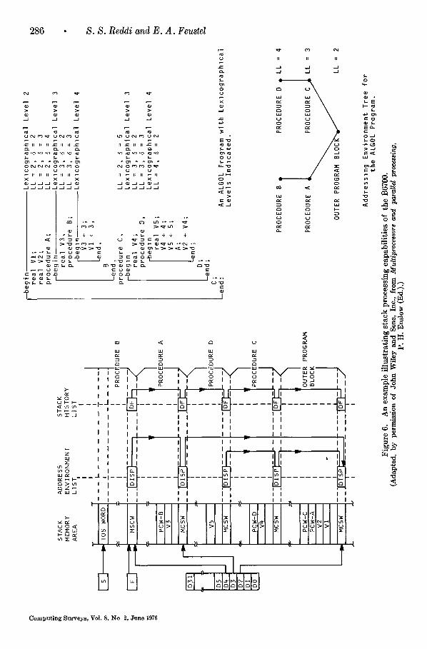
Marlc stack control words (MSCW) are used to maintain both the stack history and addressing environment lists. Figure 6 shows an example of how an MSCW is entered when a procedure is entered. The parame- ters and local variables of the procedure are entered following the MSCW and hence are referenced by addressing that is relative to the location of the MSCW. The DF fields of the MSCWs keep track of the stack history whereas the DISP fields main- tain the addressing environment list.
The variables are accessed by means of address couples. An address couple consists of the lexicographic level (LL) of the variable
and an index value ((7) (Figure 6). When a variable is specified by an address couple, one can deduce from the execution environ- ment and the lexicographie level which block or procedure specifies the variable. The display registers (DO to D31) contain the addresses of the MSCWs of the pro- cedures that are linked by the address en- vironment list to the procedure under exe- cution. By adding the index value to the contents of the appropriate display register the absolute address of the variable is generated. As an example let V1 be ref- erenced in Procedure B. Since V1 is repre- sented by the address couple (2,2) the system obtains the address of the appropri- ate MSCW from the display register D2 and adds 2 to it to obtain the address of V1. Note that the display registers must always
Computing Surveys, VoL 8, No. 2, June 1976
286 • S. S. Reddi and E. A. Feuslel
> > > > >
£ II II II £ II II £ II ~ 11 II ~ II
0 c~c~ c~ or~m o cu oeo~o o~ cJ ~J ~ ~J ~J
=..0 9 o=
i i II i i
X
N ~
g g ~
I I
Y: ' I ' ~
~>~ I I < w J I I
<
l ' ~ ~ ' I ¢ I I D-~ l
. . . . . . . . . . . . . . . . . . . . . . . . . . .
i I m I
i I I II ii I I I I I I I I
I I I I i I I I
I I
...... I~
o I I i
I i i
I I I I I , I
'~ ~- < 1 , , 11 L 1
~o '4-
$-
O- - J
m
e~
C o m p u t i n g S u r v e y s , Vo l . 8, N o 2, J u n e 1976

A Conceptual Framework for Computer Architecture
I sqrt J-
SEGMENT TRUNK
287
SEGMENT DICTIONARY
begln L . ~ Integer a, b, c
Fprocedure neg(x:y) ; ip n e g i ~nteger x, y,
L ~ X ~ x-y
Inpu t values fo r a and b, neg(a,b),
f--beg i n J i n tege r x, I x ÷ a+b, Jr-begl n
B J J Integer y, I C / ~ ~ x * * z , / / x ÷ x + y ; J~en~, Len~ sqrt(x),
prlnt (a+b+c), end
Fp
STACK AREA
Figure 7. Program representation in the B6700.
point to the address environment list and have to be changed upon procedure exit or entry to the correct MSCWs.
The stack mechanism also provides the capability of handling several active stacks by organizing them as a tree. It is beyond the scope of the present paper to go into these details. Interested readers should refer to Organick [27].
Representation, Interpretation and Transforma- tion of Information
The information processing capabilities of a computer system depend to a large extent on how the system interprets and represents the information. In this section we consider different types of representation, interpre-
tation, and transformation of information that a computer may use.
Program Representation in the Burroughs B6700: Consider the ALGOL program shown in Figure 7. The system keeps track of the program segments by means of the segment dictionary. The instruction pointer (IP) and Environment Pointer (EP) provide the physical location of the instruction in the program as well as the environment under which the instruction will be executed. (We discussed in the preceding section how the display registers which constitute the EP provide environmental information and pointers are set up in the stack area for the execution record of the program). The IP is a three-tuple of the form either (1, i, j) or (0, i, j). (1, i, 3) indicates that the instruction
Computing Surveys, VoL 8, No. 2, June 1976

288 • S. S. Reddi and E. A. Feustel
resides in the j th location of the ith seg- ment in the segment dictionary. (0, i, j) means that a "system intrinsic" (i.e., sys- tem routine) is addressed. The j th location of the ith segment in the stack trunk which contains supervisory code segments and system tables is accessed. In the example print and sqrt are system intrinsics. The segment descriptors indicate whether the segments are in the main memory and how to locate the segments on the disc if they are not in the main memory.
This kind of program representation leads to efficient memory utilization. Since the stack trunk, stack segment and stack dic- tionary compactly represent the program status and its code requirements, the work- ing sets tend to be small. Also the repre- sentation leads to sharing of programs and data. Though two programs may share a common procedure segment and hence have the same instruction pointers, their EPs are different. For further discussion of the B6700 and its system description see [27].
Representation and Interpretation of Tnstructions
Instructions determine the information flow and reflect the structure and capabilities of the system. One of the principal duties of the computer architect is to develop a com- prehensive instruction set which is simple to use but exploits the system resources to their fullest extent.
An instruction can be of zero-address, one-address or multi-address format. Zero address instructions are used in computers with stack processing where the use of operands on the top of the stack is implied by the instruction. Single- and multi-address formats are used in computer systems modeled after yon Neumann systems. Richards [29] gives an excellent discussion of the various address formats.
Addressing of operands in an instruction can be indexed or indirect. When the ad- dressing is indexed, the addresses of the operands are formed by adding or subtract- ing the contents of "index" registers to the address parts of the instruction. When the addressing mode is indirect, then the address
of the operand can be found in the location specified by the address part of the instruc- tion. The instruction repertory of a com- puter system includes instructions which allow jump operations and which handle sub- routine operations.
The instruction set can be significantly affected by the system architecture. For instance, consider tagged architecture [12] which differentiates integer operands from floating point operands at machine level. In this case it is not necessary to have sepa- rate instructions for floating point add and integer add. When an add instruction is issued, the system, by examining the ope- rands involved, decides whether it is a floating point or integer add. Another ex- ample of the effect of architecture on the instruction set is the stack processor (e.g., the B6700).
Representation and Interpretation of Data
Knuth [25] explains data as: "representa- tion in a precise, formalized language of some facts or concepts, often numeric or al- phabetic values, in a manner which can be manipulated by a computational method." Inevitably, when data represents mathemat- ical concepts or real life situations, relation- ships between the data elements are bound to exist. Since data is a representation, the precision to which the representation should be expressed becomes a factor. A properly conceived computer system should cope with the problems of relational and precision re- presentations of data.
Floating point numbers can be represented in the IBM 370 system series in short (32 bits), long (64 bits) or extended precision (128 bits) form. The system uses the byte as its basic storage unit which consists of 8 bits. When a floating point instruction like ADR (add long floating point) is to be executed, the system fetches 8 consecu- tire bytes into the central processing unit (CPU) where the left-most (or the first) byte is the one addressed in the instruction. The system recognizes the operands as float- ing point, integer, etc., by examining the in- struction rather than the operands.
In the Burroughs B6500/7500 organiza- tion, data words are distinguished as single
Computing Surveys, Vo! 8, No 2, June 1976

A Conceptual Framework for Computer Architecture • 289
precision (48 bits) or double precision (96 bits) operands by attaching 3 tag bits to every word (51 bits). Data may be refer- enced as an operand (without any qualifi- cations), and the processor knows by exa- mining the tag bits whether the operand is single or double precision. For example, when a command is issued to store an operand on the top of the stack, the word specified by the operand's address is fetched and exa- mined. If the operand is double precision, then the next word is also fetched and stored in the stack. The system recognizes the type of operand, e.g., integer, or floating point integer, or extended precision by examining the instruction. Tag bits also distinguish data words from the program code. Hence, when a job attempts either to execute data as part of the program or to modify the program, an interrupt is issued.
Transformation (or Dynamic Representation) of Information
The representation of information can be static or dynamic. However, a computer may be used to determine dynamically the changes in the representation of informa- tion that are needed for user convenience, system efficiency, and privacy. Programs are usually represented at the user level in high level languages. The representation of programs is then changed to machine level languages for execution. Changes of repre- sentation are performed for the convenience of the user. (Note that this concept makes it possible to distinguish between systems which use compilers and interpreters for program execution.) Further examples of this type of representational changes in- clude automatic transformation of ASCII characters to EBCDIC by the system.
System efficiency may dictate that differ- ent representations of information be used in different situations. Sparse matrices (matrices whose elements are mostly zero) can be economically stored by means of binary patterns and lists of nonzero values. The use of ones in binary patterns indicates that their corresponding matrix elements are nonzero. The values of these elements are obtained by choosing the appropriate values from the list. An economy in storage
results because binary patterns can usually be compacted and stored as binary words. When the matrices are not sparse it may be efficient to store them in major order fashion in rows or columns. Another ex- ample of where representations may be changed is in the storing and accessing of data elements. The elements may be stored and accessed by a table look-up or by hash coding techniques depending on the appli- cation.
Privacy considerations may also warrant making changes in the representations of information. Consider the system where a common data bank has to be shared by different users and each user is authorized to access only some portions of the data. The system may encode the data supplied by the user and store the encoded data in the bank. The conversions of encoding or privacy transformation are performed to ensure that only authorized users can gain access to a data set. When the user sup- plies the proper identification the system decodes and presents the requested data to him. Privacy transformations are discussed in [20].
Physical Organization and Control and Information Flow
I t is sometimes necessary to create new control paths among the physical resources of a computer system to exploit the paral- lelism that is present in hardware and pro- grams and to increase the system's per- formance. In such cases both the physical and control elements contribute to the desired objective. A typical application of this approach may be seen in the over- lapped operation of I/O and processor computation found in most contemporary computer systems. Sometimes information flow is controled to exhibit to the user a machine architecture that is not real. An example of this is the compatibility feature found in the IBM 370 series. We examine selected architectural features of the IBM 370 series and the CDC 6600 computers and indicate how these features can be ex- plained as a combination of physical organi- zation and control of information flow.
TBM System~370 Series. Let us now
Computing Surveys~ Vol. 8, No. 2, June 1976
290 • S. S. Reddi and E. A. Feustel
Channels IO lnlerface Control Unlls Input/Output (IO) Devices
Main SIorage - - Mul[iplexer
- - CPU-ChannelControl Lines ~[ Data Transfer Lines
I Storage Addrtss •I MAIN STORAGE
m
I
x ij I 1 I FI-"n.-P°'ntR°, 1 .....
Figure 8. Architecture of the IBM System/370. (Reprinted, by permission of IBM Corporation, from Harry Katzan, Jr., Computer organization and
the System/370.)
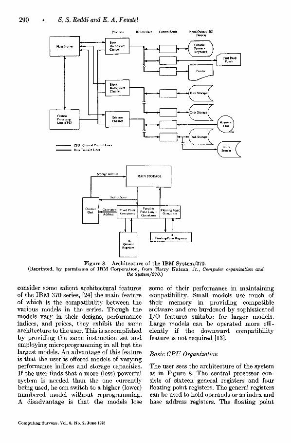
consider some salient architectural features of the IBM 370 series, [24] the main feature of which is the compatibility between the various models in the series. Though the models vary in their designs, performance indices, and prices, they exhibit the same architecture to the user. This is accomplished by providing the same instruction set and employing microprogramming in all btlt the largest models. An advantage of this feature is that the user is offered models of varying performance indices and storage capacities. If the user finds that a more (less) powerful system is needed than the one currently being used, he can switch to a higher (lower) numbered model without reprogramming. A disadvantage is that the models lose
some of their performance in maintaining compatibility. Small models use much of their memory in providing compatible software and are burdened by sophisticated I/O features suitable for larger models. Large models can be operated more effi- ciently if the downward compatibility feature is not required [13].
Basic CP U Organization
The user sees the architecture of the system as in Figure 8. The central processor con- sists of sixteen general registers and four floating point registers. The general registers can be used to hold operands or as index and base address registers. The floating point
C o m p u t i n g S u r v e y s , Vo l . 8, N o . 2, J u n e 1976

A Conceptual Framework for Computer Architecture • 291
I Ir,t I I dl W~lrd I f Sct~nd Halt 'Word 2 Thi rd Hal f Word 3
Byt~ I I I Hyl~ 2
Rt~ll~tt r RL~l~lJr Op~rmd I Op~rmd 2
~ ] RR Forn l . I o Op( 'od¢ T I I ~ t l2 Is I
I t i Rt~l~tt c I Addrcs~
Ol%r ind I I Oper,lnd 2
i o 0 . . i ~, ] x: I s~ I °, ~XF . . . . i o 7 !a I i 1~ ts le m ~o 311
I Rtgl,l( r Rt gi~lttr Address I '
[ Ol~.raml [ Ol~-rand 3 OF~rand 2 I ~ r ~ - I
00~Cod. I R, [ R, i s2 I °' i~SF . . . . . 7 i t I T 12 16116 t l 20 31 l
: I I I mmtd la t * : Address : I I Operand I Operand I I
OpCode S~ ] D, J Si Format Io 7iS Is~a l i f o 311
~I Length I I Address I Address I Operand I Operand 2 Operand I a Operand 2
I o,,c,,,,° i ,-, l ,-, i s, I o~ i s ~ l o, • 7 I t I 12 Is IS lip ~0 3t SS Format 47
Figure 9. Instruction formats of the IBM/370. (Reprinted, by permission of IBM Corporation, from Harry Katzan, Jr., Computer organization and the
registers hold floating point quantities. The registers reduce the number of memory accesses for data by storing temporary operands; this reduction in memory ac- cesses in turn reduces conflicts for memory by the I/O and CPU units. The system has a program status word (PSW) register whose contents indicate the status of the program under execution; this enables the system to handle interrupts and multi- programming.
Each model has a different engineering design. For instance, the simplest model 125 does not provide any hardware adders whereas model 165 has an address adder, a parallel adder, and serial adder. The in- struction formats for the system are shown in Figure 9. They specify the contents of registers and/or memory locations as operands. The instruction execution ap- pears to the user as sequential; however high performance models employ over- lapping of instruction and operand fetching with instruction execution, and prefetching instructions along both paths of a branch. The system hardware cannot recognize structured operands (e.g., vectors and matrices) and it is up "to the programmer to make the system recognize such operands by programming.
I /0 Handling
The responsibility of I /O handling is shared by the control unit of the CPU and I/O channels. The channels have their own registers and are capable of performing data transfers between memory and I/O devices. The CPU specifies in its I /O com- mands where the channels can find their commands in the main storage. The I/O requests for memory are given top priority (i.e., the cycle stealing technique is used). A significant feature of the I/O organization is that the user can configure the system by attaching or removing I/O devices.
Memory Organization
There is no one fixed memory organization for all the models. Models 155 and 165 provide 4K buffer storage systems in ad- dition to their main storage units. The buffer and main storage are organized into rows and columns. At the intersection of each column and row there is a block of 32 bytes, i.e., the storages are partitioned into blocks of 32 bytes and each block can be specified by a row and column. (A byte consists of 8 bits.) An address array main- tains the addresses of the elements in the buffer. When the CPU makes a storage reference, the address array is consulted to determine whether the referenced element is in the buffer. If the element is present it is sent to the CPU; otherwise the element is fetched from the main storage and dis- patched to the CPU. Then the block con- taining the element is stored in the buffer in the following manner: Blocks are trans- ferred from the main storage to the buffer columnwise, i.e., a block in column i of the main memory is transferred to column i of the buffer. The block that is to be stored in the buffer replaces the least recently used block in its column. Model 165 also uses interleaving for its memory organization.
The storage system provides a protection feature which can be used in multipro- gramming. The feature is implemented by dividing the main store into blocks (of 2048 bytes) and assigning storage keys to the blocks. Each active program has a protection key associated with it. Usually
C o m p u t i n g S u r v e y s , ~rol 8 , N o . 2 , J u n e 1976

292 • S. S. Reddi and E. A. Feustel
the operating system assigns the protection keys to the programs. A program can store in a block only when the protection key of the program matches the storage key of the block or the protection key is zero. The storage operation is inhibited and an alarm signal is given if the keys do not match and the protection key is not zero. The storage key has an extra bit which pro- tects fetch operation. If the bit is zero, only store operation is protected. Otherwise both store and fetch are protected.
CDC 6600 Memory Organization. The CDC 6600 memory hierarchy consists of a fast central storage and slow extended core storage (ECS) [32]. The central storage of 131,072 60-bit words is composed of 32 independent banks. The banks are inter- leaved to provide high block transfer rates. The computer has two cycles, major (1000 nanoseconds (nsec) and minor (100 nsec). The storage read and store cycle take one major cycle, whereas transferring a data word through the storage distribution system takes one minor cycle. There is a mechanism called the stunt box which exam- ines the requests and directs information flow in and out of the central storage. When the stunt box accepts a new access request it decides whether the bank requested is busy or free; if the bank is free the read and store cycle is initiated. If the bank is busy, the address requested is circulated within the stunt box. The stunt box can hold three circulating addresses and each circulation takes 300 nsec. Top priority is given to the addresses in circulation for access to the storage. Because of the circulation time (300 nsec) and the major cycle time (1000 nsec) the mechanism prevents permanent recirculation of any request. In case of consecutive requests to the same bank the requests are satisfied after at most two major cycles.
The stunt box is also responsible for at- taching priorities to requests coming from the central processor unit and peripheral processing units. I t prevents the situation where in the recirculating addresses read and write requests are made to the same storage location. This is because of the stunt box's out-of-order recirculation properties. I t
also checks whether the requested address violates bounds. The storage distribution system is responsible for transferring re- quests and data to and from the central storage.
The secondary storage consists of 15,744 488-bit word core memory. The 488-bit words (8 of which are parity bits) are dis- assembled to 60-bit words used in the central storage. The CPU can transfer any number of 60-bit words between the central store and ECS by simple commands. The major advantage of the ECS is that it can trans- fer blocks of information at a rate of 60 million bits/second. It may be directly ad- dressed but at a considerably slower rate. Thus, its principal use is as a high speed buffer.
CDC 6600 I /O Handling. Ten peripheral processing units (PPU) handle I/O ac- tivities. Each PPU consists of four registers and a storage unit of 4096 12-bit words. The processors are arranged in the form of a "barrel". The barrel has ten positions and each position is occupied by a PPU. There is one position called "slot" which is capable of accessing and utilizing arith- metic and logic hardware; the ten PPU's share the slot by circulating the contents of their four registers. When a PPU is in the slot it stays there for 100 nsec and uses the arithmetic and logic hardware to execute the program stored in its storage unit. A PPU instruction requires one or more steps of execution with each step taking 1000 nsec. I t can be noted that the central storage read and store cycle takes 1000 nsec which is the time interval between consecutive sharing of the slot by any PPU. The PPU can transfer data between peripheral de- vices and main memory and supervise the operation of the devices. The PPU have the capability of establishing paths to I /O devices through twelve peripheral channels. A PPU can interrupt the opera- tion of the central processor by means of an exchange jump. When an exchange jump is issued, the CPU makes an exchange between the contents of its 24 registers and the contents of the "exchange package" which starts at a location in the central storage specified by the PPU. The exchange
Computing Surveys, Vol 8, No 2, June 1976

A Conceptual Framework for Computer Architecture • 293
package consists of 16 words and specifies the new contents of the 24 central registers. Once the exchange is made the CPU starts on the new program specified by the pro- gram address register (note this register is one of the central registers). A PPU is also capable of monitoring the CPU by trans- ferring the contents of the CPU program address register to one of its registers. The CPU can also initiate the exchange jump.
Physical Organization, Control of Information Flow and Representation and Interpretation of Information
Now we consider the architectural feature of microprogramming which can only be explained when all three components of architecture are used. In the literature this feature is usually associated with system architecture. The reason for this association is that microprogramming is able to present to the user an architecture that is not a real machine architecture.
Microprogramming: Husson [21] pro-
poses the following definition: "Micro- programming is a technique for designing and implementing the control function of a data processing system as a sequence of control signals, to interpret fixed or dy- namically changeable data processing func- tions. These control signals, organized on a word basis and stored in a fixed or dy- namically changeable control memory, repre- sent the states of the signals which control the flow of information between the exe- cuting functions and the orderly transition between these signal states."
A basic microprogramming scheme [33] is shown in Figure 10. Register I contains an address which is decoded by the decoder (D). The horizontal line in the read only memory (ROM) that corresponds to the address is activated and issues signals. The signals under Matrix A control the data paths of the arithmetic units, registers, etc., of the computer system. The signals of Matrix B specify the next address to be decoded and are forwarded to Register II. Conditional jumps can be handled as shown at X. A flip-flop whose state can be controled
REGISTER II 1
REGISTER I
m i
MATRIX A MATRIX B
\ Y
CONTROL SIGNALS TO
ARITHMETIC U N I T , ETC.
X
\
FROM CONDITION F L I P - F L O P
Figure 10. A simple elementary microprogramming scheme.
Computing Surveys, Vol. 8, No. 2, June 1976

294 • S. S. Reddi and E. A. Feustel
by the previous orders issued by Matrix A decides which of the two lines in Matrix B is to be energized.
The signals issued when any line of the ROM is activated form a microorder. The format used for microorders can be either horizontal or vertical depending on how the orders are interpreted. In a horizontal format, each signal under Matrix A directly controls a gated data path. In a vertical format, the signals are organized into fields and each field controls the operations of a particular section (like an adder) of the computer system. In this format, encoding of signals is performed and hence hori- zontally formatted microorders are usually longer than vertically formatted ones. Verti- cal format microorders sometimes resemble machine language instructions in that they. have operand and address fields. Maximal parallelism at hardware level can be ex- ploited by using horizontal format micro- orders, but generating these orders can be cumbersome and time consuming.
Microprogramming has been used in widely differing contexts. For its applica- tions the interested reader should refer to Flynn and Rosin [15]. Present day large systems like the CDC 6600/7600 and IBM 360/195 do not use microprogramming for their control units. It appears that microprogramming is used in practice, not for its systematic implementation of the control section, but for its ability to offer emulation capabilities. It is interesting how- ever, to note that microprogramming is used to implement the control of the stream- ing unit of the CDC STAR 100 [23].
ARCHITECTURAL CONCEPTS AND CONSIDERA- TIONS
In this section we discuss the advantages and disadvantages of some architectural concepts. At first view they may appear to be totally unrelated to each other; however a little thought will reveal that each of these concepts can be categorized under one or a combination of the three components of architecture. Thus, a framework based on our proposal that architecture is composed of these three components can accommodate
these seemingly unrelated and diverse con- cepts. We conclude by considering some of the problems and trade-offs an architect faces in implementing these concepts and in evolving an architecture.
Array Organization
In this organization identical processors are connected in an array fashion. The ILLIAC IV is a familiar example of this type of or- ganization. The ILLIAe IV operates in a single instruction stream--multiple data stream mode (SIMD) [14], i.e., at any time all the enabled processors execute a single instruction (issued by a single control unit) on different data; the processors that are not enabled do not execute the instruction. However with suitable operating systems, it should be possible for array processors to handle the multiple instruction stream-- multiple data stream mode of operation.
The array organization is very effective in exploiting parallelism when the character- istics of the problem to be solved match the physical structure. Matrix operations pro- vide an example of this kind of problem. When all the processors are identical, man- ufacturing and maintenance are greatly simplified. A disadvantage of the array or- ganization is the poor utilization of resources that may result when the problem structure does not match the physical structure. The failure of a single processing element can hamper the operation of the entire system; a sophisticated system could, however, create new and alternate data paths for continued operation of the system.
Pipeline Organization
This organization consists of functional units arranged in a pipeline where each functional unit handles a particular task. I t is often used in commercial computer systems to improve system performance. Examples of this organization include in- struction handling in the IBM 360/91 and the arithmetic pipeline units in the TI ASC [31] and CDC STAR [19] systems. It is well suited to handling job streams where all the jobs go through the same processing
Computing Surveys, Vo! 8, No 2, June 1976

A Conceptual Framework for Computer Architecture • 295
stages. Most vector operations can, for example, be operated in this manner. Pipe- line organization loses its efficiency when some jobs require a processing sequence different trom that of the pipeline. Job de- pendencies adversely affect the job flow and hence the efficiency of this organiza- tion. Since the processing of jobs becomes "diffused"--at any instant the pipeline contains jobs at different levels of comple- t ion-interrupts and machine malfunctions cannot be handled satisfactorily. For in- stance, the architecture of IBM 360/91 has to settle for what is referred to as an "im- precise interrupt" [3].
Modular Organization
This organization consists of independent functional units (capable of performing specialized tasks) and/or processors (cap- able of performing any task). Tasks, when they are ready, are dispatched to the ap- propriate functional units or processors (usually by the supervisor of the organi- zation). The central processing unit of a CDC 6600 employs a modular organization in which there are ten independent modules. In the SYMBOL system, function modules are dedicated to perform portions of the com- puting process such as translation, memory control, garbage collection, central processor, or other processes. In contrast to array and pipeline organizations the modular organi- zation usually has a variable structure. The supervisor of the modular organization can, by establishing appropriate data flow paths, simulate any particular structure (e.g., a pipeline or an array).
An advantage of this type of organiza- tion is the enhanced performance obtain- able by using overlap and distributed func- tion computation. The organization can ensure graceful degradation of performance in ease of system component failures. Grace- ful degradation is achieved by having multiple function modules of the same type; when a module fails, its task can be assigned to another module. On the other hand, the supervisory system for such an organization tends to be complex because it has the ad- ditional responsibility of properly dispatch-
ing tasks and ensuring correct execution of the program (by preserving task prece- dences). The lack of structure in this organi- zation can increase the overhead of dis- patching tasks. The processing of jobs is "diffused" as in the pipeline organization.
Stack Processing
In this type of processing, information flow between central registers is controled in a such way that a pushdown store (or a stack) is realized [7]. New operands, which are entered into the top register of the stack, cause a "pushdown" action to occur, i.e., the contents of each register move down by one register level. Binary operations can be performed on the top two registers with the result being returned to the top register. The contents of the top register can be stored in main memory. The Burroughs B6500 and English Electric KDF-9 employ stack processing.
The following discussion of advantages and disadvantages of stack processing is based on Brooks [7]. Stack processing mini- mizes main memory data references when evaluating algebraic expressions. With stack processing, shorter program representation is possible as most operand addresses can be eliminated. I t simplifies subroutine management and compilation of source programs, especially those programs with recursive definitions. Stack processing makes it easier to handle block structured lan- guages like ALGOL. However, this type of processing is helpful only if the items that are to be processed can be made to "surface" to the top of the stack. A further disad- vantage is that many stacks, such as a stack for control and a stack for data, are often needed for satisfactory operation. When variable length fields are used, stack registers must be of ~rariable length to accommodate the values selected from these fields. This often proves to be difficult to implement.
Virtual Memory
By automatic control of information flow between the main and secondary memories, a system with virtual memory [11] gives the
Computing Surveys. VoL 8, No 2, June 1976

296 • S. S. Reddi and E. A. Feustel
programmer an illusion of operating with a main memory that is larger in capacity than the actual memory. This is accom- plished by dividing the address space into blocks of contiguous addresses and storing them in both the main and secondary memories. When the programmer makes a reference to an item not present in the main memory, the computer system auto- matically transfers the block containing the referred item from the secondary to the primary memory. The new incoming block will displace a resident block according to some fixed rule if the main memory cannot accommodate the new block. When the blocks are of variable size, one has "seg- mentation;" when they are of fixed size, the situation is referred to as "paging."
The principal advantage of virtual mem- ory is that the user can be indifferent to main memory limitations in his program- ming. He need not concern himself with the problems of overlays and memory management. The large address space pro- vided by virtual memory also simplifies multiprogramming. On the other hand, efficient utilization of the main memory is not always possible. Paged systems round up storage requests to the nearest integral number of pages and this sometimes causes appreciable loss of the main memory ("frag- mentation"). Multiprogrammed systems sometimes exhibit performance degradation which is due to a phenomenon known as "thrashing" [11].
Virtual Machines
By means of hardware and software con- trol of information flow a single computer system presents to the users multiple exact copies of the system. Each user is given the illusion that he has the complete computer system at his disposal. As an example the IBM's VM/370 offers the user a virtual IBM 370 system on which he can run any system/370 or system/360 operating system. The virtual machine, of course, runs several times slower than the real machine. The appearance of multiple copies of the basic machine is handled by the virtual machine monitor which interfaces the user's operat-
ing system and the real machine. For details concerning the implementation of the moni- tor, refer to Madnick and Donovan [26]. An advantage of virtual machines is that the users can run different operating systems on the same real machine at the same time. On the negative side, the virtual machine is several times slower because there is over- head associated with the monitor.
Parallel Processing
In this type of processing, the performance of a computer system is increased by in- troducing control and data paths among its hardware resources. For our purposes we consider parallel processing at bit and task levels. We follow the model of Shore [30] for bit level processing. Figure 11 shows a system which consists of a data memory (DM), an instruction memory (IM) and a control unit (CU). In the DM, words are stored horizontally. A bit (word) slice is any set of bits exposed by a single vertical (horizontal) cut through the DM. The word slice processing unit (WSPU) can operate on word slices whereas the bit slice process- ing unit (BSPU) operates on the bit slices. In Shore's terminology, Machine I refers to the system with only word slice processing capabilities, Machine II refers to the system with only bit slice processing capabilities and Machine III has both of the processing capabilities. (There are also Machines IV, V and VI which are best considered at task level.) I t is interesting to note that Machine I is a conventional sequential processor and Machine II is a bit serial associative proces- sor. Shore's scheme does not fit Flynn's classification [14]. Shore states: "In terms of a taxonomy introduced by Flynn, it is often stated that Machine II is a single-instruc- tion-stream, multiple-data-stream processor whereas Machine I is not. In fact, they both are. Machine I processes multiple-bit- streams a word slice at a time, whereas Machine II processes multiple-word-streams a bit slice at a time. The myopic association of multiple-data-streams with multiple-word streams is a conceptual error having nothing to do with computing power."
Shore considers the ratio of processing
Computing Surveys, Vol. 8, No. 2, June 1976

WORD . ~ SLICE
A Conceptual Framework for Computer Architecture
BIT f SLICE
, \ \ \ \ \ \ \ \ \ \ \ \ \ \ \ ' E ~ ~ / / / /
DATA / BIT / ~ SLICE MEMORY / / PROCESSING / UNIT
YA
II I
WORD SLICE PROCESSING UNIT 1
I INSTRUCTION MEMORY
Figure 11. A bit-level processing computer system.
297
hardware to memory hardware for evalu- ating the effectiveness of his machines. As can be noted, the ratio also reflects the effect of creating information flow paths by means of physical organization.
At task level there are many approaches to parallel processing. One approach consists of the functional decomposition of tasks and the dispatching to independent functional units which are specialized to execute them (e.g., the CPUs of the CDC 6600 and IBM 360/91). In another approach, the func- tional or processing units have a fixed operand and control routing structure (like a pipeline or an array) imposed on them. When the system consists of equally cap- able processing systems, its mode of opera- tion can be characterized by single instruc- tion-multiple data streams (e.g., the ILLIAC IV and PEPE) or multiple instruction- multiple data streams [14].
Central to parallel processing is the problem of recognition of parallelism in programs and task scheduling to achieve maximal concurrency. Extensive work has been done and is continuing in these problem areas. Baer [4] gives a good survey of the work done.
Tagging of Information
Iliffe [22] in his proposal of a basic language machine (BLM) suggests tagging of data and address descriptions for identification at machine level. From the tags associated with data, it is possible to recognize their precision and type (floating or fixed point, etc.). Addresses can be specified by "code words". A code word can specify a block of contiguous words which starts at the loca- tion given by the address part of the code word. The length of the block is also specified by the code word. It is possible that a code word can specify a set which consists of code words and data. It can be noted that structural data representations can be easily handled by the code word scheme.
In the BLM tags are also used to imple- ment "escape actions." Whenever the ma- chine encounters an operand whose tag specifies an escape action, the machine in- terrupts and follows the appropriate action. Numerical overflows, invalid addresses and unauthorized storage accesses can be handled by escape actions.
Iliffe claims the following advantages for his BLM. The machine can recognize the information structure of a program at ma-
Computing Surveys, Vol. 8, No. 2, June 1976

298 • S. S. Reddi and E. A. Feustel
chine level; this increases the versatility of the machine. Because of the use of code- words, the linear store structure of a con- ventional computer system is avoided. This is helpful in multiprogramming storage al- location schemes. Since data are identified by tags, instructions need not specify the data types; a single add instruction is suffi- cient to specify every add type. This results in a smaller instruction set. Also one can detect "mixed arithmetic errors" (such as addition of a floating point number to an integer) simply by examining the tags. The BL1V[ also has certain disadvantages. In a linear store every item can be addressed directly, whereas extra store accesses may have to be made in data structures com- posed of code words. Overhead is associated with memory allocation because of the data structure involved. For further discussions of tagged architecture, see Feustel [12].
Emulation
Emulation is a combined hardware-software approach to the process of modeling the physical behavior of one machine on an- other [21]. A host machine A can be made to emulate a target machine B with the aid of microprogramming. This means that A can interpret and execute the machine program written for B by means of micro- programming. As an example, an emulator is available which makes it possible to emu- late the IBM 7080 on the IBM 360/65. The emulator considers the machine in- struction of the IBM 7080 and performs necessary storage mapping conversions; it interprets and translates the instruction into a 360/65 machine instruction. Then the host machine executes the instruction.
There are many advantages to emulation. When the user changes computer systems he does not have to reprogram if he can emulate his old system on the new one. Emulation leads to compatibility, a prin- cipal feature of the IBM 370. A disadvan- tage of emulation is that it is inherently slow and does not fully utilize the resources of the host machine.
Developing an Architecture
Now we briefly consider some of the prob- lems and trade-offs an architect faces in evolving an architecture. These considera- tions are discussed within the framework of the three components of architecture. As- sume that the architect decides to make the computer system provide the capacity of ten processing units. This decision can be implemented either by replicating process- ing units (physical organization) or by time multiplexing a single processing unit (con- trol and flow of information). The first approach, which is expensive, provides higher performance and graceful perform- ance degradation in case of processing unit failures. The second is more economical but might require a sophisticated control.
Consider a system in a list processing environment. The architect wishes to pro- vide the capabilities of linked data struc- tures. He may design a conventional system without any list processing capabilities and leave the task of handling data structures to the system programmer (control and flow of information). Alternately, the archi- tect can provide data structure capabilities at machine level itself by making appropri- ate provisions at the hardware level (repre- sentation and interpretation of informa- tion). To improve the reliability of data transmission links the architect may either resort to replication and major voting or better technology (physical organization) or incorporate parity bits to the words transmitted (representation and interpreta- tion of information). Similarly, the reli- ability of adders can be improved by repli- cation or by coding the operands (e.g., AN coding [9]). Thus the architectural problems and decisions involved in implementing an architecture can be viewed in terms of the three components of architecture.
Dynamic Architectures
The computer user is becoming increasingly aware of the effect of architecture on system performance. He realizes that the array organization is ideal for solving relaxation problems, that the pipeline organization is
Computing Surveys, Vol. 8, No. 2, June 1976

A Conceptual Framework for Computer Architecture • 299
effective in handling matr ix and vector operations, and tha t stack processing makes it easier to compile and execute ALGOL pro- grams. Since no single architecture can satisfy the needs of all users, it has become desirable to have a computer system whose architecture can be defined and varied dy- namically.
)~t present, emulation is the main prin- ciple used to offer variable architectures to the user. But emulation is inherently slow and inefficient and would defeat our pur- pose, which is to speed up computat ion with dynamic architecture. Using our three component approach to architecture, it is possible to conceive a system with dynamic organization. The user can specify the architecture he needs in terms of the three components, and the system will exhibit this architecture by introducing appropriate changes in its control and data paths and by altering its representation and interpre- tat ion of information. The speed require- ments dictate tha t these changes be exe- cuted at hardware level. The authors [28] propose a system where it is possible to s tructure system resources as a pipeline, an array, or in any configuration the user m a y want. Structuring is accomplished by dynamically establishing bus paths between the resources. Thus the physical element of architecture is 'al tered' by suitable con- trol of information flow. Similarly, the other components of architecture can be altered. For instance, information flow can be controled to exhibit a stack or nonstack structure depending on the program en- vironment. By at taching tags to operands and interpreting them dynamically, we can obtain an architecture in which the third component is a variable.
REFERENCES
[1] ABRAMS, M. D.; AND STEIN, P.G. Computer hardware and software, an znterdisczplmary introduction, Addison-Wesley, Reading, Mass., 1973.
[2] AMDAHL, G. M.; BLAAUW, G. A.; AND " " h BROOKS, F P , JR, Architecture of t e
IBM System/360," IBM J. R & D. (April 1964), 87-101.
[3] ANDERSON, D. W.; SPARACIO, F. J.; AND TOMASULO, R. M. "The IBM System~360
Model 91: machine philosophy and instruc- tion handling," IBM J. R. & D. 11, 1, (Jan. 1967), 8-24.
[4] BAER, J .L . "A survey of some theoretical aspects of multiprocessing," Computing Surveys 5, 1 (March 1973), 31-80.
[5] BARNES, G. H. et al, "The ILLIAC IV com- puter," IEEE Trans. Computers (August 1968), 746-757
[6] BEIZEa, B. The architecture and engineer- ing of digital computer complexes, Vols. 1 and 2, Plenum Press, New York, 1971.
[7] BaooKs, F. P., JR., "Recent developments in computer organization," in Advances in electronic and electron physics, Vol. 18, Academic Press, New York, 1963, pp. 45-65.
[8] BROOKS, F .P , JR., "The future of computer architecture," in Proc. IFIP Congress 65, Vol. 1, Spartan Book Co., Washington, D.C., 1965, pp. 87-91.
[9] BRow~, D. T. "Error detecting and cor- recting binary codes for arithmetic opera- tions," IEEE Trans. Electronzc Computers (Sept. 1960), 333-337.
[10] BURROUGHS CORPORATION, Burroughs B 6700 information processing systems reference manual, Burroughs Corp., Detroit, Michi- gan, 1972.
[11] DENNING, P. J. "Virtual memory," Com- puting Surveys 2, 3 (Sept. 1970), 153-189.
[12] FEUSTEL, E. A. "On the advantages of tagged architecture," IEEE Trans. Com- puters (July 1973), 644-656.
[13] FLORES, I. Computer organ~zahon, Pren- tice-Hall, Englewood Cliffs, N.J., 1969.
[14] FLYNN, M.J . "Very high-speed computing systems," in Proe. of IEEE, 1966, IEEE, New York, 1966, pp. 1901-1909.
[15] FLYNN, M. J.; AND ROSIN, R . F . "Micro- programming: an introduction and a vmw- point," IEEE Trans. Computers (July 1971), 727-731.
[16] FOSTER, C. C. "Computer architecture," IEEE Trans. Computers, (March 1972), 19.
[17] FOSTER, C. C Computer architecture, Van Nostrand Reinhold Company, New York, 1970.
[18] HAUCK, E. A.; AND DENT, B. A. "Bur- roughs' B6500/B7500 stack mechanism," in AFIPS Sprang Jr. Computer Conf., 1968, Thompson Book Co., Washington, D.C., pp. 245-251.
[19] HINTZ, R. G.; .~ND TATE, D. P. "Control Data STAR-100 processor design," in COMPCON 72 Szxth Annual IEEE Comp. Soc. Internatl. Conf., IEEE, New York, 1972, pp. 1-4.
[20] HOFFMAN, L. (Ed) Securzty and privacy zn computer systems, Melville Publ. Co., Los Angeles, Cahf, 1973.
[21] HcssoN, S. S. Mieroprogramm~ng: prin- ciples and practice, Prentice-Hall, Engle- wood Chffs, N.J , 1970.
[22] ILIFFE, J. K. Basic machine principles, (2d Ed.), American Elsevmr, New York, 1972.
[23] JONES, L H.; AND MERWIN, R.E. "Trends in mmroprogramming: a second reading," IEEE Trans. Computers (August 1974), 754- 759.
Computing Surveys, VoL 8, No 2, June 1976

300 * S. S. Reddi and E. A. Feustel
[24] KATZAN, H., JR., Computer organization and the System~870, Von Nostrand Rein- hold Co., New York, 1971.
[25] KNVTH, D E. The art of computer pro- gramming, Vol. 1, Addison-Wesley, Reading, Mass., 1968.
[26] MADNICK, S. E.; AND DONOVAN, J . J . Ope- ratzng systems, McGraw-Hill, New York, 1974.
[27] ORQANICK, E. I. Computer system organi- zation, the B5700/B6700 seines, Academic Press, New York, 1974.
[28] REEDI, S. S.; AND FEUSTEL, E. A. "An approach to restructurable computer sys- tems," in Proc. Sagamore Computer Conf., 1974, Lecture notes in Computer science, Vol. 24, Springer Verlag, New York, 1975, 319-337.
[29] RICHARDS, R . K . Electronic digital systems, John Wiley & Sons, New York, 1966.
[30] SHORE, J. E "Second thoughts on parallel processing," Computers and Electrical Engi- neemng (June 1973), 95-109.
[31] TEXAS INSTRUMENTS INC. A description of the advanced scientific computer system, Equipment Group, Texas Instruments, Inc., Austin, Texas, 1973.
[32] THORNTON, J E. Design of a computer: the CDC 6600, Scott, Foresman & Co., Glen- view, Ill., 1970.
[33] WILKES, M. V.; AND STRINGER, J . B . "Mi- croprogramming and the design of the con- trol circuits in an electronic digital com- puter," in Proc. Cambmdge Phil. Soc., Part 2, 1953, Cambridge Univ. Press, New York, 1953, pp. 230-238.
Computing Surveys, Vol. 8, No 2, June 1976