a design procedure for subscale airfoils with full-scale
TRANSCRIPT

Copyright ©1996, American Institute of Aeronautics and Astronautics, Inc.
AIAA Meeting Papers on Disc, January 1996A9618595, NCC3-408, AIAA Paper 96-0635
A design procedure for subscale airfoils with full-scale leading edges for iceaccretion testing
Farooq SaeedIllinois Univ., Urbana
Michael S. SeligIllinois Univ., Urbana
Michael B. BraggIllinois Univ., Urbana
AIAA 34th Aerospace Sciences Meeting and Exhibit, Reno, NV Jan 15-18, 1996
A design procedure for subscale airfoils with full-scale leading edges that exhibit full-scale water droplet impingementcharacteristics in an incompressible inviscid flow is presented. The design procedure uses validated airfoil design, flowanalysis, and water droplet impingement simulation codes to accomplish the task. To identify and isolate importantdesign variables in the design, numerous trade studies were performed. The paper presents the results of the tradestudies and briefly discusses the role of important design variables in the subscale airfoil design. The effect of thesedesign variables on circulation, velocity distribution, and impingement characteristics is discussed along with theaccompanying implications and compromises in the design. A strategy to incorporate viscous effects into the design isalso presented. This paper also presents the design of a half-scale airfoil model with a 5-percent upper and 20-percentlower full-scale surface of the Learjet 305 airfoil leading-edge and compares its aerodynamic, as well as the dropletimpingement, characteristics with that of the Learjet 305 airfoil. (Author)
Page 1
A DESIGN PROCEDURE FOR SUBSCALE AIRFOILS WITHFULL-SCALE LEADING EDGES FOR ICE ACCRETION TESTING
Farooq Saeed,* Michael S. Seligt and Michael B. Bragg*Department of Aeronautical and Astronautica/ Engineering
University of Illinois at Urfaana-CnampaignUrfaana, Illinois 61801
ABSTRACTA design procedure for subscale airfoils with full-
scale leading edges that exhibit full-scale waterdroplet impingement characteristics in an incom-pressible, inviscid flow is presented. The design pro-cedure uses validated airfoil design, flow analysis andwater droplet impingement simulation codes to ac-complish the task. To identify and isolate importantdesign variables in the design, numerous trade stud-ies were performed. The paper presents the resultsof the trade studies and briefly discusses the roleof important design variables in the subscale airfoildesign. The effect of these design variables on circu-lation, velocity distribution and impingement char-acteristics is discussed along with the accompanyingimplications and compromises in the design. A strat-egy to incorporate viscous effects into the design isalso presented. The paper also presents the designof a half-scale airfoil model with a 5% upper and20% lower full-scale surface of the Learjet 305 airfoilleading-edge and compares its aerodynamic as wellas the droplet impingement characteristics with thatof the Learjet 305 airfoil.
NOMENCLATUREc = airfoil chord lengthC<f = airfoil drag coefficient
= airfoil lift coefficient= airfoil pitching moment coefficient= Froude number, U/^/cg= droplet inertia parameter, pwS^U/lScn= trailing-edge thickness parameter= freestream Mach number= freestream Reynolds number, pUc/fi= droplet freestream Reynolds number,
CicmoFrKKSMReRu
= airfoil surface arc length measured fromthe leading-edge
Copyright © 1996 by Farooq Saeed, MichaelS. Selig and Michael B. Bragg. Published by theAmerican Institute of Aeronautics and Astronautics,Inc. with permission.
* Graduate Research Assistant. Student MemberAIAA.
f Assistant Professor. Member AIAA.| Professor. Associate Fellow AIAA.
T — freestream static temperatureu, v = local flowfield horizontal and vertical
velocity componentsU = freestream velocityV = surface velocityVMD = volume median droplet diameterx, y = airfoil coordinatesx», Vo = initial horizontal and vertical
displacement of the dropletxm, "xm — upper and lower surface match locationsxr, xr = upper and lower surface pressure
recovery locationst>i = design velocity level for segment 1a = angle of attack relative to the chord lineae = effective angle of attack relative to
the nose section chord line, a — 7a*, a* = upper and lower surface multipoint
design angle of attack distribution/? = local impingement efficiency4>if = leading-edge arc limit7 = nose droop angleF = circulation strength normalized by UcT = circulation strength, m?/s6 = droplet diameterT; = normalized subscale airfoil chord
length, c,,/C}t\i = air viscosityp = air densitypw = water densityr = finite trailing-edge angleSubscripts:f s = full-scale airfoilt = inviscid/ = lower surfacess = subscale airfoil« = upper surfacev = viscous
INTRODUCTIONRecent aircraft accidents have raised important
flight safety issues related to the effect of ice accre-tion on airfoil and wing performance. In order toimprove flight safety, a better understanding of theeffect of ice accretion on the aerodynamic perfor-mance of modern airfoils is required. One importantstep in this process is to evaluate the aerodynamicperformance of the airfoil sections (or the wing as a

whole) at the icing conditions within the certificationicing envelop that result in the largest performancepenalties.
Since ice accretion scaling is still not well under-stood, testing at full-scale or near full-scale condi-tions is highly desirable. The available ice accretiontunnels, however, are too small to test full-scale air-foils or wings of most aircraft of interest. Numerousinvestigators have performed experimental or ana-lytical studies1"4 in an effort to evaluate full-scale ic-ing protection systems for wing sections using trun-cated airfoil models. These truncated airfoil modelsutilize a full-scale leading edge section followed by afaired or flapped aft section that, in effect, reducesthe overall length or chord of the model. To ourknowledge, however, no systematic study has beenperformed to provide insight into the design of theaft section.
With these issues in mind, a subscale model de-sign procedure was formulated with the objective ofproviding design guidance for subscale models thatsimulate full-scale water droplet impingement char-acteristics. It is assumed that ice accretion will bethe same if droplet impingement, surface geometryand surface flowfield are the same provided the samecloud properties, model surface quality, model sur-face thermodynamic characteristics exist. Using thefact that ice usually accretes only on the airfoil lead-ing edge, where the supercooled water droplets im-pinge and form ice, the subscale airfoil model is de-signed with a leading-edge geometry (first 10-20% ofchord) identical to that of the full-scale leading edge.The design of the aft section is such that it providesfull-scale flowfield and droplet impingement on theleading edge. Using this formulation, the effect ofvarious design variables on the inviscid flowfield anddroplet impingement characteristics of the subscaleairfoil was examined to obtain useful guidelines forthe design. The final design is based on viscous con-siderations as well.
The model design procedure for full-scale flowfieldand droplet impingement simulation uses validatedcomputational airfoil aerodynamics and droplet im-pingement codes,5"15 specifically, an inverse de-sign method,10 the Eppler code,8'9 XFOIL11 andAIRDROP.12
DESIGN APPROACHA conceptual illustration of the subscale airfoil de-
sign procedure is shown in Fig. 1. First, a dropletimpingement code can be used to predict the lim-its of the droplet impingement, which defines theinitial ice accretion envelop. (The droplet impinge-ment code, AIRDROP,12 is discussed later.) Once
Full Seal* Mrfoll Prdknlnvy Aktotl (PHOFCXL)
XTOLMuch
Fig. 1 A conceptual illustration of the subscaleairfoil design procedure.
the limits of impingement are known over the leadingedge of the full-scale airfoil, that part of the full-scaleairfoil geometry is fixed for the subsequent subscaleairfoil shapes. For the sake of discussion, this fixedleading-edge section, which is common to both thefull scale airfoil and the subscale airfoil, is referredto as the nose section while the remaining section ofthe subscale airfoil profile is referred to as the aft sec-tion. The aft section of the subscale airfoil is thendesigned to provide full-scale flowfield and dropletimpingement on the nose section of the subscale air-foil.
An initial geometry for the aft section is obtainedthrough the use of a multipoint inverse airfoil designcode10 (PROFOIL). The design of this intermediateairfoil, from which the aft section of the subscaleairfoil is derived, is governed by several constraints,namely, the scale of the subscale airfoil, the upperand lower surface thickness and slope at the junctionbetween the nose and aft sections (xm, a?m), and adesired form for the pressure recovery characteris-tics. Apart from these constraints, additional conti-nuity and closure constraints that form an integralpart of the inverse design methodology10 are alsosatisfied in order to achieve a physically possible de-sign. A multi-dimensional Newton iteration schemeis employed to satisfy these constraints. The depen-dent and independent Newton variables10 used inthe design are listed Table 1. Once the constraintsare satisfied, the aft section is combined with thenose section to form a subscale airfoil.
The potential flow over both the subscale andthe full-scale airfoils is then analyzed using the
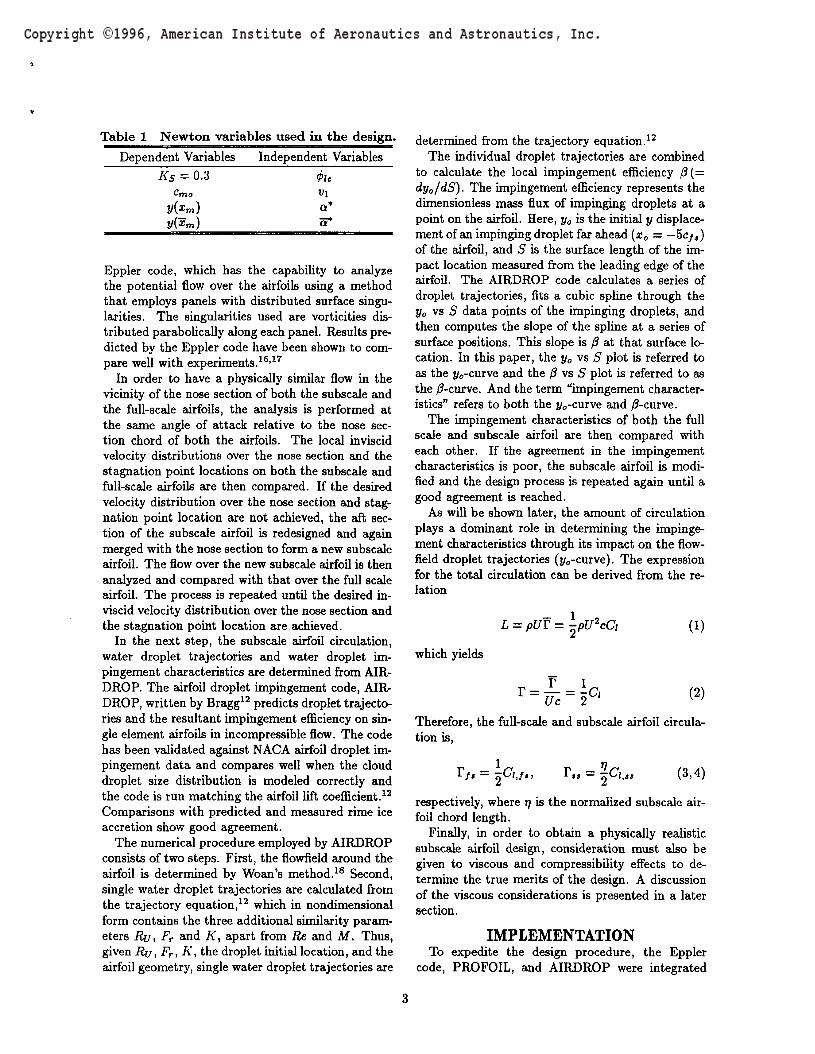
Table 1 Newton variables used in the design.Dependent Variables Independent Variables
Ks = 0.3 ^Cmo Vi
J/(zm) a*
Eppler code, which has the capability to analyzethe potential flow over the airfoils using a methodthat employs panels with distributed surface singu-larities. The singularities used are vorticities dis-tributed parabolically along each panel. Results pre-dicted by the Eppler code have been shown to com-pare well with experiments.16'17
In order to have a physically similar flow in thevicinity of the nose section of both the subscale andthe full-scale airfoils, the analysis is performed atthe same angle of attack relative to the nose sec-tion chord of both the airfoils. The local inviscidvelocity distributions over the nose section and thestagnation point locations on both the subscale andfull-scale airfoils are then compared. If the desiredvelocity distribution over the nose section and stag-nation point location are not achieved, the aft sec-tion of the subscale airfoil is redesigned and againmerged with the nose section to form a new subscaleairfoil. The flow over the new subscale airfoil is thenanalyzed and compared with that over the full scaleairfoil. The process is repeated until the desired in-viscid velocity distribution over the nose section andthe stagnation point location are achieved.
In the next step, the subscale airfoil circulation,water droplet trajectories and water droplet im-pingement characteristics are determined from AIR-DROP. The airfoil droplet impingement code, AIR-DROP, written by Bragg12 predicts droplet trajecto-ries and the resultant impingement efficiency on sin-gle element airfoils in incompressible flow. The codehas been validated against NACA airfoil droplet im-pingement data and compares well when the clouddroplet size distribution is modeled correctly andthe code is run matching the airfoil lift coefficient.12
Comparisons with predicted and measured rime iceaccretion show good agreement.
The numerical procedure employed by AIRDROPconsists of two steps. First, the flowfield around theairfoil is determined by Woan's method.18 Second,single water droplet trajectories are calculated fromthe trajectory equation,12 which hi nondimensionalform contains the three additional similarity param-eters RU, Fr and K, apart from Re and M. Thus,given RU, Fr, K, the droplet initial location, and theairfoil geometry, single water droplet trajectories are
determined from the trajectory equation.12
The individual droplet trajectories are combinedto calculate the local impingement efficiency /?(=dy0/dS). The impingement efficiency represents thedimensionless mass flux of impinging droplets at apoint on the airfoil. Here, y0 is the initial y displace-ment of an impinging droplet far ahead (x0 = — 5c/,)of the airfoil, and S is the surface length of the im-pact location measured from the leading edge of theairfoil. The AIRDROP code calculates a series ofdroplet trajectories, fits a cubic spline through they0 vs S data points of the impinging droplets, andthen computes the slope of the spline at a series ofsurface positions. This slope is /? at that surface lo-cation. In this paper, the y0 vs S plot is referred toas the y0-curve and the /? vs S plot is referred to asthe /?-curve. And the term "impingement character-istics" refers to both the y0-curve and /?-curve.
The impingement characteristics of both the fullscale and subscale airfoil are then compared witheach other. If the agreement in the impingementcharacteristics is poor, the subscale airfoil is modi-fied and the design process is repeated again until agood agreement is reached.
As will be shown later, the amount of circulationplays a dominant role in determining the impinge-ment characteristics through its impact on the flow-field droplet trajectories (j/0-curve). The expressionfor the total circulation can be derived from the re-lation
L = pUT =
which yields
(1)
(2)
Therefore, the full-scale and subscale airfoil circula-tion is,
f,« (3,4)
respectively, where T) is the normalized subscale air-foil chord length.
Finally, hi order to obtain a physically realisticsubscale airfoil design, consideration must also begiven to viscous and compressibility effects to de-termine the true merits of the design. A discussionof the viscous considerations is presented in a latersection.
IMPLEMENTATIONTo expedite the design procedure, the Eppler
code, PROFOIL, and AIRDROP were integrated
0.2-1
o.o-
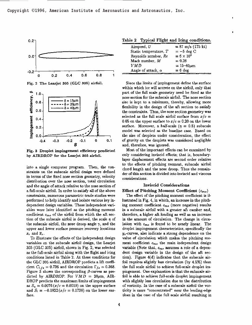
Table 2 Typical Flight and Icing conditions.
-0.2-H i0.60 0.2 0.4 0.6 0.8
Fig. 2 The Learjet 305 (GLC 305) airfoil.
^ 1.0-,
Impi
ngem
ent
effic
ienc
y
0
0
0
0
.8-
.6-
.2-
——— 8 = 15um----- 8 = 20um i——— .. 5 = 40um a
•HA....---•7l
111
-0.4 -0.3 -0.2 -0.1 0 0.1S
Fig. 3 Droplet impingement efficiency predictedby AIRDROP for the Learjet 305 airfoil.
into a single computer program. Then, the con-straints on the subscale airfoD design were definedin terms of the fixed nose section geometry, velocitydistribution over the nose section, total circulationand the angle of attack relative to the nose section ofa full-scale airfoil. In order to satisfy all of the aboveconstraints, numerous parametric trade studies wereperformed to help identify and isolate various key in-dependent design variables. These independent vari-ables were later identified as the pitching momentcoefficient cmo of the airfoil from which the aft sec-tion of the subscale airfoil is derived, the scale rj ofthe subscale airfoil, the nose droop angle 7, and theupper and lower surface pressure recovery locationsxr and xr.
To illustrate the effects of the independent designvariables on the subscale airfoil design, the Learjet305 (GLC 305) airfoil, shown in Fig. 2, was selectedas the full-scale airfoil along with the flight and icingconditions listed in Table 2. At these conditions forthe GLC 305 airfoil, AIRDROP predicts a lift coeffi-cient dj, = 0.736 and the circulation T/, = 0.368.Figure 3 shows the corresponding /^-curves as pre-dicted by AIRDROP. For VMD = 200m, AIR-DROP predicts the maximum limits of impingementas 5U = 0.0076 (x/c = 0.0019) on the upper surfaceand Si = -0.1822 (x/c = 0.1738) on the lower sur-face.
Airspeed, UStatic temperature, TReynolds number, ReMach number, MVMDAngle of attack, a
= 87 m/s (175 kt)= -5 deg C= 6 x 106
= 0.28= 15-40/rai= 6 deg
Since the limits of impingement define the surfacewithin which ice will accrete on the airfoil, only thatpart of the full scale geometry need be fixed as thenose section for the subscale airfoil. The nose sectionsize is kept to a minimum, thereby, allowing moreflexibility in the design of the aft section to satisfythe constraints. Thus, the nose section geometry wasselected as the full scale airfoil surface from x/c =0.05 on the upper surface to x/c — 0.20 on the lowersurface. Moreover, a half-scale (77 = 0.5) subscalemodel was selected as the baseline case. Based onthe size of droplets under consideration, the effectof gravity on the droplets was considered negligibleand, therefore, was ignored.
Most of the important effects can be examined byonly considering inviscid effects; that is, boundary-layer displacement effects are second order relativeto the effects of pitching moment, subscale airfoilchord length and the nose droop. Thus the remain-der of this section is divided into inviscid and viscousconsiderations.
Inviscid ConsiderationsEffect of Pitching Moment Coefficient (cmo)
The effect of the pitching moment coefficient is il-lustrated in Fig. 4, in which, an increase in the pitch-ing moment coefficient cmo (more negative) resultshi a subscale airfoil with a greater aft camber and,therefore, a higher aft loading as well as an increasein the amount of circulation. The change in circu-lation with cmo is found to be nearly linear. Thedroplet impingement characteristics, specifically thej/0-curves, also indicate a strong dependence on thevalue of circulation which makes the pitching mo-ment coefficient cmo the main independent designvariable (Note that, cmo assumes a role of a depen-dent design variable in the design of the aft sec-tion). Figure 4(d) indicates that the subscale air-foil requires slightly less circulation (by 4.5%) thanthe full scale airfoil to achieve full-scale droplet im-pingement. One explanation is that the subscale air-foil is able to achieve full-scale droplet impingementwith slightly less circulation due to the distributionof vorticity. In the case of a subscale airfoil the vor-ticity is more "concentrated" near the leading-edgethan in the case of the full scale airfoil resulting in

(a)
(d)
2.8-1
2.1
V 1.4-
0.7-
0.0-0.2 0 0.2 0.4 0.6 0.8 1 1.2
X/C-0.10-,
-0.15-
-0.20-
-0.25-0.25 -0.2 -0.15 -0.1 -0.05 0 0.05
S
-0.25 -0.2 -0.15 -0.1 -0.05 0.05
0.07Ty/c
-0.07-
-0.21-0.5 -0.2 0.1 0.4 0.7
X/C
Fig. 4 The effect of pitching moment coefficienton (a) the velocity distribution, (b) initial dis-placement, (c) droplet impingement efficiencyand (d) the tangent droplet trajectories.
(a)
(b)
(c)
(d)
2.8-]
2.1-
V 1.4-
0.7-
0.0-0.2 0 0.2 0.4 0.6 0.8 1 1.2
-0.25 -0.2 -0.15 -0.1 -0.05 0.05
0.07-1
Fig. 5 The effect of chord length on (a) the ve-locity distribution, (b) initial displacement, (c)droplet impingement efficiency and (d) the tan-gent droplet trajectories.
a greater upwash in close proximity of the airfoil.Thus a lower value of overall circulation is requiredto simulate full scale droplet impingement.Effect of Chord Length (77)
To examine the effect of normalized subscale chordlength 77 on the design, subscale airfoils were de-signed for three different values of 77, that is, 0.5,0.7 and 0.9. Initially, the three subscale airfoilswere designed such that they produced the sameamount of circulation as the full scale airfoil. Figure
5 shows the resulting velocity distribution impinge-ment characteristics and the airfoil shapes. Theresults indicate that as the scale of the subscalemodel is reduced, the aft-loading on the airfoil in-creases significantly in order for it to produce thesame amount of circulation. The mismatch in thej/o-curves, Fig. 5(b), suggests that subscale modelsrequire less circulation to achieve full scale impinge-ment characteristics. Moreover, the results also sug-gest that the smaller the scale, the less circulationrequired to simulate full scale droplet impingement

(a) 2.8i
2.1H
V 1.4
0.7-
0.0
-0.22-0.3 -0.25 -0.2 -0.15 -0.1 -0.05 0 0.05
(c)
-0.3 -0.25 -0.2 -0.15 -0.1 -0.05 0 0.05S
0.07-,
y/c-0.07-
-0.21-0.5 -0.2 0.1 0.4
x/e0.7
Pig. 6 Results showing (a) the velocity distri-bution, (b) initial displacement, (c) droplet im-pingement efficiency and (d) the tangent droplettrajectories at the matched conditions.
characteristics. The subscale airfoils shown in Fig. 6were designed such that the impingement character-istics, specifically, the y0-curves were matched. Thematch in y0-curves was achieved by designing sub-scale airfoils with reduced circulation as comparedwith the ones in Fig. 5. The results also indicatethat the amount of circulation required to simulatefull scale droplet impingement vary from (0.955F/,)for TJ of 0.5 to (0.983r,,) for 77 of 0.9.Effect of Nose Droop Angle (7)
The effect of the nose droop angle 7, shown inFig. 7, becomes obvious from Fig. 8 which illustrates
Fig. 7 The nose droop angle.
(a)
(b)
(c)
(d)
2.1-
1.4-
0.7-
0.0-0.2 0 0.2 0.4 0.6 0.8 1 1.2
-0.21-0.5 0.7
Fig. 8 The effect of nose droop on (a) the ve-locity distribution, (b) initial displacement, (c)droplet impingement efficiency and (d) the tan-gent droplet trajectories.
the usefulness of the nose droop in reducing the highaft-loading on airfoils. In order to keep the angle ofattack relative to the nose section chord constant

for both the full scale and subscale airfoils, the sub-scale airfoil with a nose droop is analyzed at an ef-fective angle of attack ae which takes into accountthe nose droop angle. As a result, the subscale air-foils with nose sections droop downwards are ana-lyzed at higher angles of attack than those withoutthe nose droop. Figure 8 shows the results of thesubscale airfoil design with different nose droop an-gles for the same value of circulation as that of thehalf-scale model without the nose droop. The resultsindicate that the nose droop results in an increasein the camber of the subscale airfoil and, therefore,the subscale airfoil circulation. Moreover, the sub-scale airfoils with the nose drooped downwards alsooperate at higher absolute angles of attack definedby ae. As a result of this increase, the impingementcharacteristics show a mismatch. By decreasing theamount of circulation by an appropriate amount, themismatch was removed as shown in Fig. 9. The re-duction in the value of circulation as compared withthat for the full scale airfoil varies from (0.955F/,)for 7 of 0 deg to (0.892F/,) for 7 of -3 deg.Other Effects
The upper and lower surface pressure recovery lo-cations xr and 5Fr (see Fig. 10) control to a greatextent the shape of the airfoil near its trailing edge.Although, the effect of moving the pressure recoverylocations xr and afr results in a significant amountof improvement in the velocity distributions and ul-timately the viscous characteristics, the change inthe droplet impingement characteristics is, however,small.
The above study, based on inviscid considerationsalone, illustrates the effect of different independentdesign variables on the subscale airfoil design. Theresults indicate that subscale airfoils require less cir-culation to simulate full scale airfoil droplet impinge-ment characteristics. The pitching moment coeffi-cient cmo can be used effectively to achieve the de-sired amount of circulation. Since subscale airfoilstend toward high aft-loading in order to simulate thedesired impingement characteristics, a nose droopcan be used effectively to offset the high aft-loadingto a large extent. The above study also reveals thatsubscale airfoils with a nose droop require even lesscirculation to achieve the desired impingement char-acteristics. Moreover, a subscale airfoil with a nosedroop (downwards) must operate at a higher abso-lute angle of attack to simulate full scale impinge-ment characteristics over its nose section. Oper-ation at high absolute angles of attack makes thesubscale airfoil highly susceptible to flow separationand, therefore, it becomes necessary to evaluate theperformance by means of a viscous analysis of the
(a) 2.81
2.1-
1.4-
0.7-
0.0-0.2 0 0.2 0.4 0.6 0.8 1 1.2
x/c(b) -0.18-,
-0.19-
V. -0.20-
-0.21-
-0.22-0.25 -0.2 -0.15 -0.1 -0.05 0 0.05
S
c) 0.8-
0.6-
P 0.4-
0.2-
o.n--0.3 -0.25 -0.2 -0.15 -0.1 -0.05 0 0.05
S
(d)y/c
-0.07-
-0.21-0.5 -0.2 0.1 , 0.4
X/C0.7
Fig. 9 Results showing (a) the velocity distri-bution, (b) initial displacement, (c) droplet im-pingement efficiency and (d) the tangent droplettrajectories at the matched conditions.
flowfield over the subscale airfoil at the design con-ditions.
Viscous ConsiderationsTo determine the true merits of the design, a vis-
cous flowfield analysis must form an essential partof the design. For the purpose of viscous flowfieldanalysis, XFOIL was utilized. XFOIL is a modifiedversion of the ISES code19 which has been success-fully applied to the design and analysis of airfoils forvarious applications varying from human-poweredaircraft20 to high Reynolds number transonic trans-port. XFOIL utilizes a fully compatible laminar and
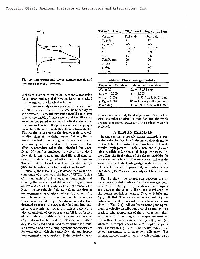
Table 3 Design Flight and Icing conditions.
Fig. 10 The upper and lower surface match andpressure recovery locations.
turbulent viscous formulation, a reliable transitionformulation and a global Newton iteration methodto converge onto a flowfield solution.
The viscous analysis was performed to determinethe effect of the presence of the viscous boundary onthe flowfield. Typically inviscid flowfield codes overpredict the airfoil lift-curve slope and the lift on anairfoil as compared to viscous flowfield codes since,in a viscous flowfield, the presence of boundary-layerdecambers the airfoil and, therefore, reduces the <7j.This results in an error in the droplet trajectory cal-culation since at the design angle of attack, the in-viscid flowfield is for a higher lift coefficient, andtherefore, greater circulation. To account for thiseffect, a procedure called the "Matched Lift Coef-ficient Method" is employed, in which, the inviscidflowfield is analyzed at matched lift coefficient in-stead of matched angle of attack with the viscousflowfield. A brief outline of this procedure as ap-plied to the subscale airfoil design is as follows.
Initially, the viscous Cij, is determined at the de-sign angle of attack with the help of XFOIL. UsingCij,, an angle of attack a,-j, is found such thatrunning the inviscid flowfield code at ontj, producesan inviscid C\ which matches Cij,, the viscous C/.Next, the inviscid flowfield as well as the dropletimpingement characteristics of the full scale airfoilare determined at Qrjjj and set as the target forthe subscale airfoil design. A subscale airfoil is thendesigned to match the target flowfield and impinge-ment characteristics. Once a match is achieved, aviscous analysis of the subscale airfoil is performedat the matched conditions to determine the viscousCi>tt. As in the full scale airfoil case, an inviscida,-,,, is calculated and is used to determine the invis-cid flowfield and droplet impingement characteristicsfor comparison with the target flowfield and dropletimpingement characteristics. If the desired charac-
VariableU,m/aT, deg CReMc, mVMD, urnQ, deg7. deg<*«, deg
Full scale87-56 x 106
0.281.020606
Subscale87-53x 106
0.280.5206-39
____Table 4 The converged solution.Dependent Variables Independent VariablesKs = 0.3cmo = -0-065y(xm = 0.05)y(xm = 0.20)T = 6 deg
<t>u = 189.53 degt>i = 2.133a* =8.93,11.93,14.93 dega* = 1.17 deg (all segments)xr - 0.0114c xr = 0.4746c
teristics are achieved, the design is complete, other-wise, the subscale airfoil is modified and the wholeprocess is repeated again until the desired match isachieved.
A DESIGN EXAMPLEIn this section, a specific design example is pre-
sented with the objective to design a half-scale modelof the GLC 305 airfoil that simulates full scaledroplet impingement. Table 3 lists the flight andicing conditions for the final design, whereas, Ta-ble 4 lists the final values of the design variables forthe converged solution. The subscale airfoil was de-signed with a finite trailing-edge angle T = 6 deg.The effects due to compressibility were also consid-ered during the viscous flow analysis of both the air-foils.
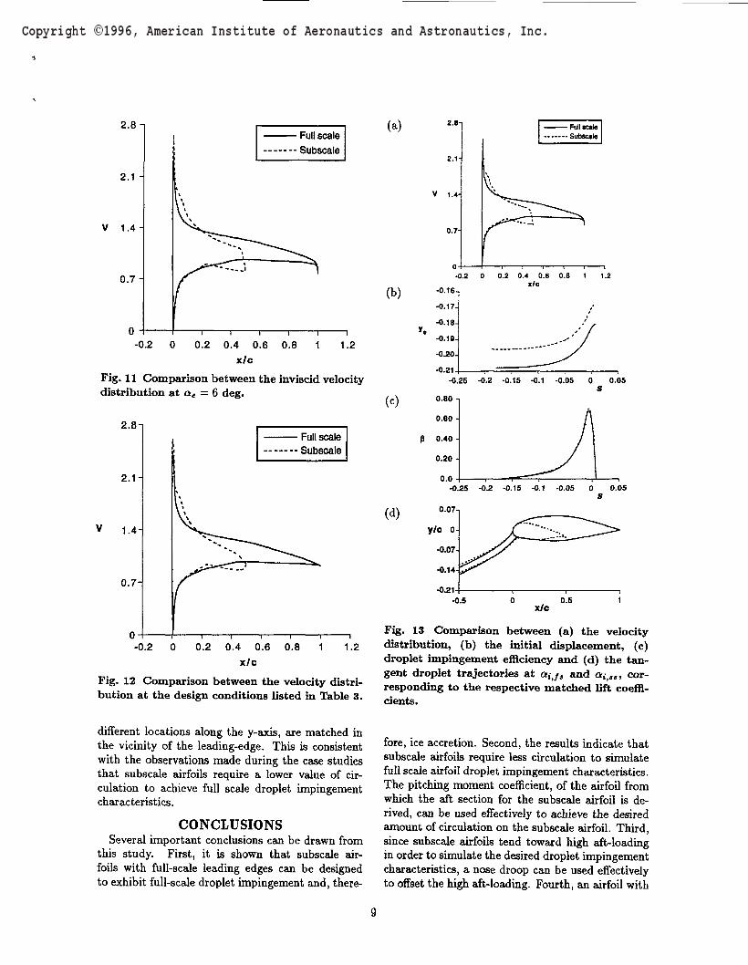
Fig. 11 shows the comparison between the in-viscid velocity distributions for the converged solu-tion at ae — 6 deg. Fig. 12 shows the compari-son between the velocity distributions (viscous) atthe design conditions, where, C/,/, = 0.7690 andC/,*» = 0.6074. The respective inviscid velocity dis-tributions for the matched lift coefficient case areshown in Fig. 13(a). All the figures show good agree-ment in velocity distribution over the common nosesection. The comparison of the impingement char-acteristics corresponding to the respective matchedlift coefficient cases is shown in Fig. 13(b) and (c),whereas, a comparison of tangent droplet trajecto-ries is shown in Fig. 13(d). The results indicate ex-cellent agreement in impingement efficiency. Thetangent droplet trajectories, although originating at
2.8 -\
2.1 -
V 1.4-
0.7-
(a)
-0.2 0 0.2 0.4 0.6 0.8 1 1.2x/c
Fig. 11 Comparison between the inviscid velocitydistribution at ae = 6 deg.
2.8-1
2.1-
V 1.4-
0.7-
• Full scale• Subscale
-0.2 0 0.2 0.4 0.6 0.8 1 1.2x/c
Fig. 12 Comparison between the velocity distri-bution at the design conditions listed in Table 3.
different locations along the y-axis, are matched inthe vicinity of the leading-edge. This is consistentwith the observations made during the case studiesthat subscale airfoils require a lower value of cir-culation to achieve full scale droplet impingementcharacteristics.
CONCLUSIONSSeveral important conclusions can be drawn from
this study. First, it is shown that subscale air-foils with full-scale leading edges can be designedto exhibit full-scale droplet impingement and, there-
(b)
(c)
2-8-1
2.1-
V 1.4-
1.2
0,05
0.05
-0.21-0.5
Fig. 13 Comparison between (a) the velocitydistribution, (b) the initial displacement, (c)droplet impingement efficiency and (d) the tan-gent droplet trajectories at <*,•_/, and a,-,,,, cor-responding to the respective matched lift coeffi-cients.
fore, ice accretion. Second, the results indicate thatsubscale airfoils require less circulation to simulatefull scale airfoil droplet impingement characteristics.The pitching moment coefficient, of the airfoil fromwhich the aft section for the subscale airfoil is de-rived, can be used effectively to achieve the desiredamount of circulation on the subscale airfoil. Third,since subscale airfoils tend toward high aft-loadinghi order to simulate the desired droplet impingementcharacteristics, a nose droop can be used effectivelyto offset the high aft-loading. Fourth, an airfoil with

Pig. 14 The final subscale airfoil and the Learjet305 airfoil.
a nose droop (downwards) must operate at a higherabsolute angle of attack in order to keep the sameangle of attack relative to its nose section as the fullscale airfoil to simulate full scale impingement char-acteristics. Operation at high absolute angles of at-tack makes the subscale airfoil highly susceptible toflow separation and, therefore, it becomes necessaryto integrate the viscous analysis of the flowfield overthe subscale airfoil into the design process. Fifth, toincorporate viscous and compressibility effects, the"matched lift coefficient method" outlined in the pa-per was applied successfully in the final design ex-ample.
Although, the design method outlined hi this pa-per is only limited to a point design, the method canbe extented to a multipoint design similar in lines tothe existing multipoint inverse airfoil design meth-ods by integrating viscous boundary-layer equationsand the droplet trajectory equation with the inverseairfoil design method.
ACKNOWLEDGMENTSThis work has been sponsored by NASA Lewis Re-
search Center under grant NCC3-408. We would liketo thank Reuben Chandrasekharan of Learjet, Inc.for providing NASA Lewis with the Learjet GLC 305airfoil used in this study. Also, helpful discussionswith Tom Ratvasky, Gene Addy and Tom Bond ofNASA Lewis are gratefully acknowledged.
REFERENCES^auger, H.H., and Englar, K.G. "Analysis of
Model Testing in an Icing Wind Tunnel," Rep. No.SM 14993, Douglas Aircraft Co., Inc., May 14, 1954.
2Sibley, P.J., and Smith, R.E., Jr. "Model Test-ing in an Icing Wind Tunnel," Rep. No. LR 10981,Lockheed Aircraft Cor., Inc., Oct. 14, 1955.
3Langmuir, I., and Blodgett, K., "A MathematicalInvestigation of Water Droplet Trajectories," ArmyAir Forces TR 5418, Feb. 1946.
4Glahn, U. H. von, "Use of Truncated FlappedAirfoils for Impingement and Icing Tests of Full-Scale Leading-Edge Sections," NACA RM E56E11,July 1956.
5Soinne, E. and Laine, S., "An Inverse BoundaryElement Method for Single Component Airfoil De-sign," Journal of Aircraft, Vol. 22, No. 6, June 1985,pp. 541-543.
60rmsbee, LA. and Chen, A.W., "Multiple ele-ment Airfoils Optimized for Maximum Lift Coeffi-cient," AIAA Journal, Vol. 10, No. 12, December1972, pp. 1620-1624.
7Kennedy, J.L. and Marsden, D.J., "A Poten-tial Flow Design Method for Multicomponent Air-foil Sections," Journal of Aircraft, Vol. 15, No. 1,January 1978, pp. 47-52.
8Eppler, R., "Direct Calculation of Airfoils fromPressure Distribution," NASA TT F-15, 417, March1974. (Translated from Ingenieur-Archive, Vol.25,No.l, 1957, pp. 32-57)
9Eppler, R., Airfoil Design and Data, Springer-Verlag, New York, 1990.
10Selig, M.S. and Maughmer, M.D., "A Multi-point Inverse Airfoil Design Method Based on Con-formal Mapping," AIAA Journal, Vol. 30, No. 5,1992, pp. 1162-1170.
nDrela, M., "XFOIL: An Analysis and DesignSystem for Low Reynolds Number Airfoils." Pro-ceedings of the Conference on Low Reynolds Num-ber Aerodynamics, Norte Dame, Indiana, June 1989.In Lecture Notes in Engineering, No. 54, Springer-Verlag, New York, pp. 1-12.
12Bragg, M.B., "Rime Ice Accretion and Its Effecton Airfoil Performance," Ph. D. Dissertation, TheOhio State University, Columbus, Ohio, 1981.
13Bragg, M.B., "The Effect of Geometry on AirfoilIcing Characteristics," Journal of Aircraft, Vol. 21,No. 7, July 1984, pp. 505-511.
14Bragg, M.B., "A Similarity Analysis of theDroplet Trajectory Equation," AIAA Journal,Vol. 20, No. 12, Dec. 1982, pp. 1681-1686.
15Ruff, A.G. and Berkowitz, "User's Manual forthe NASA Lewis Ice Accretion Prediction Code(LEWICE)," NASA CR 185129, 1990.
16Somers, D.M., "Design and Experimental Re-sults for a Flapped Natural-Laminar-Flow Airfoilfor General Aviation Application," NASA TP-1865,June 1981.
17Maughmer, M.D., and Somers, D.M., "Designand Experimental Results for a High-Altitude, LongEndurance Airfoil," Journal of Aircraft, Vol. 26,No. 2, Dec. 1989, pp. 148-153.
18Woan, C.J., "Fortran Programs for Calculatingthe Incompressible Potential Flow About a Single
10

Element Airfoil Using Conformal Mapping," TheOhio State University, Aeronautical and Astronau-tical Research Laboratory, TR AARL 80-02, Colum-bus, Ohio, January 1980.
19Drela, M., and Giles, M.B., "ISES: A Two-Dimensional Viscous Aerodynamic Design andAnalysis Code," AIAA 87-0424, Jan. 1987.
20Drela, M., "Low-Reynolds Number Airfoil De-sign for the MIT Daedalus Prototype: A CaseStudy," Journal of Aircraft, Vol. 25, No. 8,Aug. 1988.
11