a framework and architecture for multi-robot...
TRANSCRIPT

Rafael FierroMARHES LaboratorySchool of Electrical and Computer EngineeringOklahoma State UniversityStillwater, OK USA
Aveek DasJohn SpletzerJoel EspositoVijay KumarJames P. OstrowskiGeorge PappasCamillo J. TaylorGRASP LaboratoryUniversity of PennsylvaniaPhiladelphia, PA USA
Yerang HurRajeev AlurInsup LeeSDRL LaboratoryUniversity of PennsylvaniaPhiladelphia, PA USA
Greg GrudicDepartment of Computer ScienceUniversity of Colorado at BoulderBoulder, CO USA
Ben SouthallSarnoff CorporationPrinceton, USA
A Framework andArchitecture forMulti-RobotCoordination
Abstract
In this paper, we present a framework and the software architecturefor the deployment of multiple autonomous robots in an unstructuredand unknown environment, with applications ranging from scoutingand reconnaissance, to search and rescue, to manipulation tasks, tocooperative localization and mapping, and formation control. Oursoftware framework allows a modular and hierarchical approach toprogramming deliberative and reactive behaviors in autonomous op-eration. Formal definitions for sequential composition, hierarchicalcomposition, and parallel composition allow the bottom-up devel-
The International Journal of Robotics ResearchVol. 21, No. 10–11, October-November 2002, pp. 977-995,©2002 Sage Publications
opment of complex software systems. We demonstrate the algorithmsand software on an experimental testbed that involves a group of car-like robots, each using a single omnidirectional camera as a sensorwithout explicit use of odometry.
KEY WORDS—multi-robot coordination, hierarchical hy-brid systems, vision-based control
1. Introduction
It has long been recognized that there are several tasks thatcan be performed more efficiently and robustly using multiplerobots (Donald, Gariepy, and Rus 2000; Khatib et al. 1996).In fact, there is extensive literature on control and coordina-
977

978 THE INTERNATIONAL JOURNAL OF ROBOTICS RESEARCH / October-November 2002
tion for multiple mobile robots, and application to tasks suchas exploration (Burgard et al. 2000), surveillance (Feddemaand Schoenwald 2001), search and rescue (Jennings, Whelan,and Evans 1997), mapping of unknown or partially knownenvironments (Taylor 2002), distributed manipulation (Rus,Donald, and Jennings 1995; Mataric, Nilsson, and Simsar-ian 1995), distributed sensor fusion and localization (Stroupe,Martin, and Balch 2001; Roumeliotis and Bekey 2000), andtransportation of large objects (Stilwell and Bay 1993; Sugarand Kumar 2000; Kosuge et al. 1999). See, for instance, Parker(2000) for a review of contemporary work in this area.
In our previous work, a high-level language CHARON wasintroduced for describing hierarchical hybrid systems (Aluret al. 2000a). The problem of controlling a group of robots hasbeen addressed in a series of papers: trajectory generation isaddressed in Fierro et al. (2002) and Belta and Kumar (2001);switched control in Desai, Kumar, and Ostrowski (1999) andFierro et al. (2001b); vision-based formation control is pre-sented in Das et al. (2002); and cooperative localization andmanipulation is addressed in Spletzer et al. (2001). In this pa-per, in contrast, we focus on the design of software and controlbehaviors for cooperative multi-robot systems. Our goal is todescribe a set of tools that allows the development of con-trollers and estimators for multi-robot coordination. The toolsconsist of a framework for developing software components,an architecture for control and estimation modules, and a setof decentralized control, planning and sensing algorithms. Inour software framework, each component, for example eachrobot, is an agent. The agent can be a parallel composition ofmany sub-agents, for example, sensor agents, actuator agents,and other software agents that operate in parallel. The multi-robot control task is decomposed within each agent into a setof modes or behaviors. Modes can consist of high-level be-haviors such as planning a path to a goal position, as well aslow-level tasks such as obstacle avoidance. We allow for se-quential composition of modes to enable changes in behavior.Hierarchical composition allows high-level deliberative con-trollers to be composed with low-level reactive controllers.We use a high-level language to formally describe how andwhen transitions between these modes are to take place inorder to achieve a set of global objectives.
2. Motivation
There is extensive literature on the control of robot manipu-lators or mobile robots in structured environments, and robotcontrol is a well-understood problem area. However, tradi-tional control theory mostly enables the design of controllersin a single mode of operation, in which the task and the modelof the system are fixed. A similar problem exists in developingestimators in the context of sensing.
When operating in unstructured or dynamic environmentswith many different sources of uncertainty, it is very difficultif not impossible to design controllers that will guarantee per-
formance even in a local sense. In contrast, we also know thatit is relatively easy to design reactive controllers or behav-iors that react to simple stimuli or commands from the envi-ronment. This is the basis for the subsumption architecture(Brooks 1986) and the paradigm for behavior-based robotics(Mataric 1995; Arkin 1998).
Our goal in this paper is to establish a paradigm that allowsus to design simple components whose performance can beanalyzed and predicted using control theory and dynamics,and to develop tools that allow us to construct hierarchicalsystems with switches in behavior that can be used in thedevelopment of intelligent robotic systems. Specifically, wedescribe an architecture and a high-level language with for-mal semantics, CHARON, that can be used to describe multi-agent, networked robotic systems with multiple control andestimation modes, and discrete communication protocols ina principled way. The architecture allows the development ofcomplex multi-robot behavior via hierarchical and sequentialcomposition of control and estimation modes, and parallelcomposition of agents. We present our ongoing work to au-tomatically generate control and simulation code from thehigh-level language description.
We also illustrate the application of these ideas to the devel-opment of an experimental platform of multiple mobile robotsthat cooperate in performing the following tasks: (a) searchingand identification of colored objects; (b) cooperative localiza-tion of targets and robots; (c) cooperative two-dimensionalmapping; (d) cooperative manipulation and transportation ofobjects; and (e) formation control.
The experimental results demonstrate the benefits and thelimitations of mode switching and the methodology underly-ing the implementation of cooperative control of multi-roboticsystems.
3. Modeling Language and SoftwareArchitecture
The last few years have seen active research in the field of dis-tributed robotics, and in the development of architectures formulti-robot coordination. These architectures have focused onproviding different capabilities to the group of robots. For in-stance, ALLIANCE (Parker 1998), a behavior-based softwarearchitecture, has focused on fault tolerant cooperative control.In Morrow and Khosla (1997), robot skills are expressed asfinite state machines (FSMs) under the Chimera software en-vironment. The coordination of robots for large-scale assem-bly has been considered in Simmons et al. (2000). Klavinsand Koditschek (2000) have presented tools for composinghybrid control programs for a class of distributed roboticsystems. This approach assumes that a palette of controllersfor individual tasks is available. These controllers i.e., robotbehaviors are sequentially composed using the techniquesintroduced in Burridge, Rizzi, and Koditschek (1999). These

Fierro et al. / Multi-Robot Coordination 979
ideas are applied to the design of assembly tasks as found inautomated factories.
The three-tier (3T) layered architecture is presented inSchreckenghost et al. (1998). In this work the problem ofmanaging life support for remote facilities is considered. Aplanner coordinates the tasks across subsystems. An explicitseparation between deliberative and reactive tasks enables ap-propriate human intervention in autonomous operation. Re-cently, the CLARAty architecture for robotic autonomy wasintroduced in Volpe et al. (2001). This two-tiered approachconsiders a tight coupling between planning and executionwithin the decision layer. The decision layer interacts withthe functional layer. The functional layer consists of softwaremodules for estimation, status reporting and system operationorganized in a conventional object-oriented manner. Both ar-chitectures, 3T and CLARAty, are being implemented on someNASA robotic projects.
Our software architecture has some similarities with theworks described above. It is object-oriented and supports hi-erarchical composition of agents and behaviors or modes. Inaddition, we use the theory of hybrid systems (Alur et al.2000b; Fierro and Lewis 1997; van der Schaft and Schu-macher 2000) to formally analyze and design multi-roboticcooperative systems. For this purpose, we have developedCHARON, an acronym for Coordinated Control, Hierarchi-cal Design, Analysis, and Run-Time Monitoring of HybridSystems.
3.1. Modeling Language
CHARON is a language for modular specification of inter-acting hybrid systems based on the notions of agents andmodes. For a hierarchical description of the system architec-ture, CHARON provides the operations of instantiation, hid-ing, and parallel composition on agents, which can be usedto build a complex agent from other agents. The discrete andcontinuous behaviors of an agent are described using modes.For a hierarchical description of the behavior of an agent,CHARON supports the operations of instantiation and nestingof modes. Furthermore, features such as weak pre-emption,history retention, and externally defined Java functions, facili-tate the description of complex discrete behavior. Continuousbehavior can be specified using differential as well as alge-braic constraints, and invariants restricting the flow spaces,all of which can be declared at various levels of the hierarchy.The modular structure of the language is not merely syntactic,but is also reflected in the semantics so that it can be exploitedduring analysis. The key features of CHARON are summa-rized below.
• Architectural hierarchy: The building block for de-scribing the system architecture is an agent that com-municates with its environment via shared variables andalso communication channels. The language supportsthe operations of composition of agents for concur-
rency, hiding of variables for information encapsula-tion, and instantiation of agents to support reuse.
• Behavioral hierarchy: The building block for describ-ing a flow of control inside an atomic agent is a mode. Amode is basically a hierarchical state machine, that is,a mode can have submodes and transitions connectingthem. Variables can be declared locally inside any modewith standard scoping rules for visibility. Modes can beconnected to each other through entry and exit points.We allow the instantiation of modes so that the samemode definition can be reused in multiple contexts. Fi-nally, to support exceptions, the language allows grouptransitions from default exit points that are applicableto all enclosing modes, and to support history retention,the language allows default entry transitions that restorethe local state within a mode from the most recent exit.
• Discrete and continuous variable updates: Discreteupdates are specified by guards labeling transitions con-necting the modes. Such updates correspond to mode-switching, and are allowed to modify variables throughassignment statements.
Variables in CHARON can be declared analog, andthey flow continuously during the continuous updatesthat model the passage of time. The evolution of analogvariables can be constrained in three ways: differentialconstraints (e.g., by equations such as x = f (x, u)),algebraic constraints (e.g., by equations such as y =g(x, u)), and invariants (e.g., x − y < c) which limitthe allowed durations of flows. Such constraints can bedeclared at different levels of the mode hierarchy.
It should be noted that CHARON is a modeling language:it supports nondeterminism for both discrete and continuousupdates, it is suitable for describing the system as well as theassumptions about the environment in which the system issupposed to operate, and for describing the same system atdifferent levels of abstraction. The language constructs pri-marily facilitate the description of control flow, but it alsosupports calls to externally defined Java functions which canbe used to write complex data manipulations. More detailsabout the language, the global semantics and the formal de-scription are presented in Alur et al. (2000a).
3.2. Software Architecture
3.2.1. Architectural Modeling with Agents
The architecture proposed here allows the development ofcomplex multi-robot behavior via hierarchical and sequentialcomposition of control and estimation modes, and parallelcomposition of agents.1
1. Note that our definitions of composition do not satisfy the constraintsrequired by Burridge, Rizzi, and Koditschek (1999), where the definition ofcomposition comes with guarantees for global performance.

980 THE INTERNATIONAL JOURNAL OF ROBOTICS RESEARCH / October-November 2002
formation,role[1…n],obstacleDetected,wallDetected
Coordination Agent
Robot_Group Agent
groupState
obstacleSensed[1...n],wallSensed[1…n]targetSensed[1…n]
controlEstimator[1...n]
Fig. 1. Agent hierarchy diagram.
At the highest level of the hierarchy, the multi-robot systemis represented by two interacting agents: a coordination agentand a robot-group agent. The coordination agent reduces tothe specification of communication channels between robotagents, and the specification of parameters for transitions andthe instantiation of each agent within the robot-group agent.This is schematically illustrated in Figure 1.
Robot agents can receive estimates of the obstacles fromother robots, and commands and specifications from the hu-man operator on input channels, and it can send its own infor-mation to other robots or to the human operator on the outputchannels (see Figure 2).
The architecture diagram in Figure 3 shows a parallel com-position of control and estimator agents operating concur-rently with off-the-shelf black boxes (shown shaded). Thecontrol agent switches between modes described in the nextsubsection. The estimator agent on the left in the dotted boxrepresents different logical sensors that can be developed fromone vision system.
3.2.2. Behavioral Modeling with Modes
The state of a robot agent is given by xxx ∈ Rn. Its evolution isdetermined by a set of differential equations
xxx = fq(xxx,uuu), uuu = kq(xxx,zzz), (1)
where uuu ∈ Rm is the control vector, q ∈ Q ⊂ Z is the controlmode for the agent, Q is a finite set of control mode indices,Z denotes the set of positive integers, and zzz ∈ Rp is the in-formation about the external world available either throughsensors or through communication channels. The robot agentcontains modes describing behaviors that are available to therobot.
The controller-Top mode depicted in Figure 4 consists oftwo submodes: leader mode and follower mode. These sub-modes become active based on the state of the discrete variablerole from the coordination agent.
There are three submodes within the leader mode: go-ToGoal, obstacleAvoidance, and wallFollowing. Initially, theleader’s mode is goToGoal and both wallDetected and obsta-
cleAvoided are false. If one of these becomes true, the transi-tion from goToGoal to one of wallFollowing and obstacleAv-oidance occurs accordingly, and the reverse transition willbe enabled if the variable is reset. If both variables becometrue, obstacleAvoidance mode will be active. A leader will en-ter wallFollowing mode if the Boolean variable wallDetectedbecomes true, obstacleAvoidance mode if obstacleDetectedbecomes true, respectively. This behavioral structure is illus-trated in Figure 5.
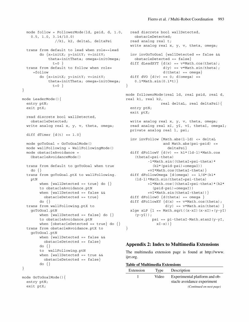
If a robot agent is in follower mode, it will follow its leaderkeeping a desired distance and relative bearing. The estimatoragent provides all the required information about the state ofthe leader. The follower robot uses this information in orderto compute its own control velocities. We have developedand implemented a number of controllers for this purpose.Figure 6 illustrates the textual description in CHARON ofthe follower mode. The separation-bearing controller (SBC)implemented within this mode is presented in Section 5.
In the next section, we proceed to illustrate how to exploitthe modular structure of CHARON in implementing the abovearchitecture. We consider the problem of controlling multiplemobile, autonomous robots for mission-critical applicationsand stringent requirements on safety. A detailed CHARONcode for a two-robot example is given in the Appendix.
4. Real-Time Framework for Multi-RobotCoordination
Our multi-threaded software implementation encapsulates al-gorithms and data in the usual object-oriented manner to-gether with control of a thread within which the algorithmswill execute, and a number of events that allow communica-tion with other objects. At the top of the hierarchy, the algo-rithms associated with the objects are likely to be planners,while at bottom they will be interfaces to control and sensinghardware. The planner objects are able to control the exe-cution of the lower level objects to service high-level goals.To offer platform independence, only the lowest level objectsshould be specific to any hardware, and these should have

Fierro et al. / Multi-Robot Coordination 981
formation, role[1...n],obstacleDetected,wallDetected
Robot_1
groupState
obstacleSensed[1...n],targetSensed[1…n],wallSensed[1...n]
controlEstimator[1…n]
Robot_2 Robot_n. . .
Fig. 2. Robot-group agent.
Frame_Grabber Agent
Estimator Agent
Motion_Controller Agent
Control Agent
Robot_k
obst
acle
Sen
sed[
k]
wallSensed[k] controlEstimator[k] groupState formation role[k]
obstacleDetected
wallD
etectedta
rget
Sen
sed[
k]
Fig. 3. A robot agent consists of estimator agent, control agent and hardware interface agents.
Controller_Top
read discrete int role;read discrete bool wallDetected, obstacleDetected;
Follower_Mode
Leader_Moderole == lead role == follow
role == follow
Fig. 4. Robot modes within the Controller Top mode.

982 THE INTERNATIONAL JOURNAL OF ROBOTICS RESEARCH / October-November 2002
Leader_Mode
read discrete bool wallDetected, obstacleDetected;
wallDetected== true &&obstacleDetected == false
ObstacleAvoidance obstacleDetected == true
Go_To_Goal WallFollowingwallDetected == false
wallDetected == true
obstacleDetected == true
wallDetected==false &&obstacleDetected == false
Fig. 5. Submodes within the leader mode.
param ld, psid, d, k1, k2, deltaL, deltaPsi;read analog real xI, yI, thetaI, omegaI, vI;write analog real x, y, theta, omega, v;private analog real l, psi;inv invFollow {Math.abs(l - ld) <= deltaL
and Math.abs(psi- psid) <= deltaPsi}
diff dFollowV {d(v)== k1(ld-l)* Math.cos(thetaI+psi-theta)-l*Math.sin((thetaI+psi-theta)(k2(psid-psi)+omegaI))+vI* Math.cos(thetaI-theta)}
diff dFollowOmega {d(omega)==1/d (k1(ld-l)*Math.sin(thetaI+psi-theta)+l*Math.cos((thetaI+psi-theta)(k2(psid-psi)+omegaI))+vI*Math.sin(thetaI-theta))}
diff dFollowXY { d(x) == v*Math.cos(theta);d(y) == v*Math.sin(theta)}
alge aLP { l==Math.sqrt((x-xI)(x-xI)+(y-yI)(y-yI));psi==pi-thetaI-Math.atan2(y-yI,x-xI)}
Follower_Mode
Fig. 6. Description of the follower mode.

Fierro et al. / Multi-Robot Coordination 983
a consistent interface for communication with the planningobjects that control their execution.
Vision-based control algorithms have been incorporatedinto the multi-threaded software architecture for such basicfunctionality as obstacle avoidance, wall following, mappingand localization, and group behavior. Thus, each robot can beeasily programmed to follow a wall while avoiding obstacles,and looking for targets that might specify the goal location.With multiple robots, each robot may also have the flexibil-ity of following other robots. This software is used by robotsto explore long passages in buildings and build maps of theenvironment for possible reconstruction with applications toimmersion or for scouting and reconnaissance. Other exam-ples of group behavior include formation keeping, collabo-rative mapping and manipulation. We can form two-robot orn-robot teams by parallel composition of robot agents. Theavailability and sharing of information between the robotsallows us: (a) to design modes within estimator agents thatcan exploit sensory information obtained from other robots;and (b) to design the coordination agent to initiate or triggermode-switching within the controller agent.
In the next subsections, we describe the real-time imple-mentation of the software objects that realize the architectureproposed here.
4.1. Experimental Platform
The GRASP Laboratory Clodbuster (CB) robots served asthe testbed for all experiments. The platform is based upon acommercially available radio control truck from Tamiya Inc.,with significant modifications. The CB version used for thiswork lacks on-board processing. Wireless video is transmittedat 2.4 GHz, back to a remote computer where all vision andcontrol algorithms are processed. Control servo signals arethen sent back in turn from the computer to the CB via aparallel port interface. An image of the CB platform is shownin Figure 7 (Extension 1).
The CB platform uses an omnidirectional camera (Para-camera from Remote Reality) as its sole sensor. One of theprimary advantages of these catadioptric sensors is that theyafford a single effective point of projection (Baker and Nayar1998). This means that after an appropriate calibration, everypoint in the omnidirectional image can be associated with aunique ray through the focal point of the camera. This allowsazimuth and elevation angles to every teammate (and target)visible in the 360◦ field-of-view image to be estimated, mak-ing the camera an ideal choice for cooperative sensing tasks,as will be discussed in the following section.
The robot has a servo controller on board for steering anda digital proportional speed controller for forward/backwardmotion. A parallel port interface, also designed in our lab,allows us to drive up to eight mobile robot platforms froma single Windows NT workstation. A video receiver, locatedat the host computer, feeds the signal to a frame grabber that
is able to capture video at full frame rate (30 Hz) for imageprocessing. This yields a video signal in a format for viewingand recording, as well as image processing.
4.2. Sensors
Sensors are organized hierarchically within the estimatoragent shown in Figure 3. The estimator agent will share infor-mation with the coordination and robot agents. The logicalsensors or detectors work in parallel and all use the informa-tion provided by the Frame_Grabber agent. This is graphi-cally depicted in Figure 8.
A target or other robots can be identified in the image usinga YUV color space based feature extractor, which provides ro-bustness to variations in illumination (Spletzer et al. 2001).Three-dimensional color models are generated a priori fromimages of the target at numerous distances, orientations, andillumination levels. These data are stored in a pair of look-uptables to speed image processing. During operation, the tar-get detection algorithm, the blobExtractor sensor, is initiallyapplied to the entire image and can run at frame rate (30 Hz).
Once the target is acquired, the sensor switches to targettracking mode (Extension 2). The target tracking scheme issimple yet robust. The YUV-based color extractor actuallyprocesses the entire image very quickly, segmenting up toeight colors from each pixel with a single binary operation.
4.2.1. Range Mapping
The range map (see Figure 7) is obtained by applying a Sobelgradient to the omnidirectional image. The resulting edges inthe image are the features of interest. By assuming a groundplane constraint, the distance to the nearest feature in the sec-tor of interest is determined from the its relative elevationangle to the mirror. This provides a range map to all obstaclesat frame rate.
4.2.2. Localizer
Our localization algorithm employs an extended Kalman fil-ter (EKF) to match landmark observations to an a priori mapof landmark locations. The Localizer object uses the blobEx-tractor sensor agent to determine the range and the bearing ofan observed landmark. If the observed landmark is success-fully matched, it is used to update the vehicle position andorientation. The lower left image of Figure 7 shows a typicalimage used for localization.
In the experiment depicted in Figure 9, we let the robottrace an open-loop circular trajectory in a measured area withfixed landmarks. The robot usually sees very few landmarks.The overhead camera gives us an idea of the actual groundtrajectory of the robot. The average error is approximately2 cm. This is particularly challenging as we use a simplifiedkinematic model, and we lack odometry.

984 THE INTERNATIONAL JOURNAL OF ROBOTICS RESEARCH / October-November 2002
Fig. 7. The mobile robot platform with Omnicam (top), typical image and the ensuing range map (bottom).
ObstacleDetector
RelativeState Observer
CollisionDetector
TargetDetector
Color BlobExtractor
Edge Detector
obst
acle
Sen
sed[
k]w
allS
ense
d[k]
controlEstimator[k]
Frame Grabber
targetSensed[k]
RangeMapper
Fig. 8. Description of the Estimator agent.

Fierro et al. / Multi-Robot Coordination 985
InitialPosition (1,1)
From localizer
Groundtruth
Groundtruth
Fig. 9. Localization results for a circular trajectory.
4.2.3. Velocity Estimator
The leader-following control object described in the next sec-tion requires reliable estimation of the linear velocity and an-gular velocity of a leader mobile robot. The velocity estimatoralgorithm is also based on an EKF. It uses the blobExtractorsensor to determine the range ρ and the bearing β of the ob-served leader. In addition, the filter requires a sensor model,and a model of the dynamics of the leader and follower robots.
The EKF is based on a kinematic model of the nonholo-nomic mobile robot
x = u1 cos θ, y = u1 sin θ,
θ = u1
ltan φ, φ = λ(u2 − φ),
(2)
where l is the body length, u2 is the steering command,|φ| < 70◦ is the steering angle, and λ ≈ 4s−1 is a parameterthat depends on the steering servo time constant and wheel-ground friction. The control vector is given by uuu = [u1 u2]T
where u1 is the robot’s forward velocity and u2 is the steeringcommand. More details of the EKF are provided in Das et al.(2001).
4.2.4. Mapper
When communication is enabled between the robots, central-ized controllers and estimators are possible. Figure 10 shows
the results of a cooperating mapper enabled by sharing infor-mation between, and coordinating, three robots. The mapperrequires two robots to stay fixed at any instant, while a thirdrobot, called the mapper, explores unknown areas. In the fig-ure, three robots develop a map of a 4 × 4m2 test area withglobal map updates at 3–5 Hz.
4.3. Controllers
4.3.1. Obstacle Avoidance and Wall Following
The wall following works by using inputs from two sensors:a wall detector and an obstacle detector. Both take as inputthe image from an edge detector, and use range map data tofind the relative position of the wall/obstacle. The wall de-tector has a 40◦ field of view from 160◦–200◦ with respect tothe robot frame, where 90◦ reflects the forward direction ofthe robot. A line is fit to these points using a RANSAC (ran-dom sampled consensus) algorithm (Hartley and Zisserman2000), which gives us a line fit robust to outliers. From this weare able to extract the relative position and orientation of therobot to the wall. We use input–output feedback linearizationtechniques to design a proportional–derivative (PD) controllerto regulate the distance of the vehicle to the wall, Figure 11(top). Wall following can be considered as a particular caseof path following (De Luca, Oriolo, and Samson 1998). Thus,the kinematics, in terms of the path variables, arc length s andorientation θt , becomes

986 THE INTERNATIONAL JOURNAL OF ROBOTICS RESEARCH / October-November 2002
ACTUAL EXTRACTED
Fig. 10. Cooperative mapping with three robots, in an environment with real and simulated walls.
s = v1 cos θp, d = v1 sin θp, θp = v1
ltan φ, φ = v2.
(3)
In this case θt = π
2and θp = θ − θt . Assuming the robot is to
follow the wall with a piecewise constant velocity v1(t), thecontroller is given by
u = tan−1
[l
v21 cos θp
(kp(d0 − d) − kvv1 sin θp)
], (4)
where u(t) is the steering command, v1(t) is the linear ve-locity, and kp and kv are positive design controller gains. Acritically damped behavior is obtained by setting kv = 2
√kp.
The obstacle detector picks up objects in its 80◦ forward-staring field of view. Since the position and orientation rela-tive to the wall are known, the detector is able to discriminatewhich obstacles are actually the wall, and which are truly ob-stacles that must be avoided. Mode switching between wallfollowing and obstacle avoidance is accomplished by givingpriority to the latter. Experimental results are depicted in Fig-ure 11 (axes units are inches).
5. Control of Groups of Robots
Problems in formation control of multiple vehicles that havebeen investigated include assignment of feasible formations(Tabuada, Pappas, and Lima 2001), getting into formation(Chen and Luh 1994; Beni and Liang 1996), and mainte-nance of formation shape (Yamaguchi and Burdick 1998).Approaches to modeling and solving these problems havebeen diverse, ranging from paradigms based on combining re-active behaviors (Balch and Arkin 1998; Burridge, Rizzi, andKoditschek 1999) to those based on leader-following graphs(Desai, Ostrowski, and Kumar 2001) and virtual structures(Tan and Lewis 1997; Lawton, Young, and Beard 2000).
We consider a team of n nonholonomic mobile robots thatare required to follow a prescribed trajectory while maintain-ing a desired formation. The desired formation may changebased on environmental conditions or higher-level commands.In this paper, we assume that the robots are velocity controlledplatforms and have two independent inputs vi andωi . The con-trol laws are based on I/O feedback linearization. This meanswe are able to regulate two outputs. Moreover, we assume thatthe robots are assigned labels from 1 through n which restrictthe choice of control laws. Robot 1 is the leader of the group. Itis assumed that R1 knows where to go. We do not consider ex-plicitly the trajectory planning for the leader, but instead focuson the algorithms and software required for the group to fol-low the leader. Follower robots have no information about theleader’s trajectory. Each follower robot is able to estimate thestate of its leader by using extended Kalman filter techniques(Das et al. 2001). Thus, a follower can maintain a prescribedseparation and bearing from its adjacent neighbors. Follow-ing our previous work (Desai, Ostrowski, and Kumar 2001),we consider two controllers that enable this behavior in thenext two subsections: (a) the Separation–Bearing Controller(SBC); and (b) the Separation–Separation Controller (SSC).
5.1. Separation–Bearing Control
In this mode of control, the desired separations ldij
and bearingsψd
ijdefine the desired shape of the formation locally as shown
in Figure 12 (top). The kinematics of the nonholonomic i-robot are given by
xi = vi cos θi, yi = vi sin θi, θi = ωi, (5)
where xi ≡ (xi, yi, θi) ∈ SE(2). The control velocities forthe follower are given by
vj = sij cos γij − lij sin γij (bij + ωi) + vi cos(θi − θj ), (6)

Fierro et al. / Multi-Robot Coordination 987
d
θt
θ
s
lW
ALL
-80 -60 -40 -20 0 20 40 60 80-60
-40
-20
0
20
40
60
80
100
120
* Obstacle
Avoidance
o Wall Following
Obstacle
Wall
Fig. 11. The wall following, sample wall following configuration, and corresponding mode versus position results (see alsoExtension 3).
ωj = 1
dj
[sij sin γij + lij cos γij (bij + ωi) + vi sin(θi − θj )],(7)
where
γij = θi + ψij − θj , (8)
sij = k1(ld
ij− lij ), (9)
bij = k2(ψd
ij− ψij ), k1, k2 > 0. (10)
The closed-loop linearized system becomes
lij = k1(ld
ij− lij ), ψij = k2(ψ
d
ij− ψij ), θj = ωj . (11)
In the following theorem, we provide a stability result for theSBC.
THEOREM 1. Assume that the reference trajectory g(t) issmooth, the reference linear velocity is large enough andbounded, i.e., vi > Vmin > 0, the reference angular veloc-ity is small enough, i.e., ‖ωi‖ < Wmax and the initial relativeorientation is bounded, i.e.,
∥∥θi − θj
∥∥ < εθ < π . If the con-trol velocities (6)–(7) are applied to Rj , then system (11) isstable and the output system error of the linearized systemconverges to zero exponentially.
While the two output variables in eq. (11) converge to thedesired values arbitrarily fast (depending on k1 and k2), the be-havior of the follower’s internal dynamics, θj , depends on the
controlled angular velocity ωj . In our analysis we have con-sidered the internal dynamics required for a complete studyof the stability of the system. Let the orientation error be ex-pressed as
eθ = ωi − ωj . (12)
After incorporating the angular velocity for the follower (7),we obtain
eθ = − vi
dj
sin eθ + η(www, eθ), (13)
where www depends on the output system error and referenceangular velocity ωi . η(·) is a nonvanishing perturbation forthe nominal system (eq. (13) with η(·) = 0), which is itself(locally) exponentially stable. By using the stability of per-turbed systems (Khalil 2002), it can be shown that system (13)is stable, and thus the stability result in Theorem 1 follows.
Figure 12 shows a view of a leader-following experiment.Shown superimposed on the ground plane are actual datapoints collected from an overhead camera installed in our labfor ground truth purposes.
Figure 13 depicts the estimated linear and angular velocityof the leader robot, and the measured separation and bearing.We choose ld = 0.6 m and ψd = 180◦. The robustness of thesystem is verified when we manually hold the follower for afew seconds at t ≈ 65 s.

988 THE INTERNATIONAL JOURNAL OF ROBOTICS RESEARCH / October-November 2002
(xi,yi,θi)
lij
vi, ωiψij
Ri
dj
(xj,yj,θj)
vj, ωjRj
X
Y
Fig. 12. The SBC and formation control experimental setup (see also Extension 1).
5.2. Separation–Separation Control
In this mode of control, robot Rk follows two leaders Ri andRj with desired separations ld
ikand ld
jk, respectively. This con-
troller can be used to define a triangle formation provided thatRj followsRi with the appropriate separation and bearing (seeFigure 14).
In this case the control velocities for the follower robotbecome
vk = (14)
sik sin γjk − sjk sin γik + vi cosψik sin γjk − vj cosψjk sin γik
sin(γjk − γik),
ωk = (15)
−sik cos γjk+sjk cos γik−vi cosψik cos γjk+vj cosψjk cos γik
dk sin(γjk−γik).
The closed-loop linearized system is
lik = k1(ld
ik− lik), ljk = k1(l
d
jk− ljk), θk = ωk. (16)
In the following theorem, we provide a stability result for theSSC. Details are described in Fierro et al. (2002).
THEOREM 2. Assume that the reference linear velocityalong the trajectory g(t) ∈ SE(2) is lower bounded, i.e.,vi > Vmin > 0, the reference angular velocity is also bounded,i.e., ‖ωi‖ < Wmax , the relative velocity δv ≡ vi −vj and orien-tation δθ ≡ θi − θj are bounded by small positive numbers ε1,ε2, and the initial relative orientation ‖θi(t0) − θk(t0)‖ < π .If the control velocities (14)–(15) are applied to Rk, then sys-tem (16) is stable and the output system error of the linearizedsystem converges to zero exponentially.
Figure 15 depicts ground-truth data for triangular forma-tion experiments. The desired formation was an isosceles tri-angle where both followers maintained a distance of 1.0 m

Fierro et al. / Multi-Robot Coordination 989
0 20 40 60 80 100 120 1400.2
0.3
0.4
0.5
0.6
0.7
0.8Separation
Am
plit
ud
e(m
)
Time (s)
0 20 40 60 80 100 120 140150
155
160
165
170
175
180
185
190
195
200Bearing
ψ(d
eg)
Time (s)
0 20 40 60 80 100 120 1400
0.1
0.2
0.3
0.4
0.5
0.6Estimated linear velocity (leader)
v 1(m
/s)
Time (s)
0 20 40 60 80 100 120 140-0.1
0
0.1
0.2
0.3
0.4
0.5
0.6Estimated angular velocity (leader)
ω1
(rad
/s)
Time (s)
Fig. 13. Leader-following experimental results.
from the lead robot. The results are for the most part satisfac-tory, with mean separation errors of 3.2% and 5.5% for thetwo followers.
5.2.1. Distributed Manipulation
The ability to maintain a prescribed formation allows therobots to manipulate objects and transport them to a desired lo-cation. Experiments were conducted using a box as the objectto be manipulated. In Figure 16, the initial team configurationis centered around the box, with the goal to flow the formationalong a trajectory generated by the leader. By choosing a con-straining formation geometry, the box is kept in contact withall three robots during the formation flow. Several snapshotsfrom a sample run are shown in Figure 16.
Despite the control strategy not accounting for changes inthe object pose, the formation was typically successful in itsmanipulation task over the tested trajectories. These exper-
iments, while not an exhaustive investigation of distributedmanipulation, demonstrate the potential for a vision-basedformation control application.
5.3. Discussion
We have discussed two types of controllers for the Leader-Following mode for controlling and coordinating a team ofmobile robots. These are not the only controllers possible.In Spletzer et al. (2001), we describe controllers that are par-ticularly useful for cooperative localization and manipulation,and we exploit the characteristics of the omnidirectional cam-eras. However, as shown in Fierro et al. (2001b, 2002), thesecontrollers can be used to control a team of n robots in arbi-trarily complicated formations. Furthermore, in Fierro et al.(2001b) a simple algorithm for assigning one of the two con-trollers discussed above is developed. This mode-switchingalgorithm, although derived from heuristics based on the

990 THE INTERNATIONAL JOURNAL OF ROBOTICS RESEARCH / October-November 2002
(xi,yi,θi)
vi, ωi
X
Y
lik
(xk,yk,θk)
vk, ωk
(xj,yj,θj)
vj, ωj
ljk
Rk
Ri
Rj
dk
Omni-Camera
Video transmitter
Collar foridentification
Fig. 14. The SSC and experimental setup.
2 1 0 1 22
1
0
1
2
3
4
Dist (m.)
Dis
t (m
.)
Initial
Final
1
2
3
1
23
2 1 0 1 2 3
2
1
0
1
2
3
4
Dist (m.)
Dis
t (m
.)
1
2
3
1
2
3
Fig. 15. Sample ground-truth data for trajectories for a triangular formation (see also Extension 5).

Fierro et al. / Multi-Robot Coordination 991
Fig. 16. Distributed manipulation demonstration.
sensor characteristics and the dynamics of the robot, is provento be stable for a three-robot formation.
The assignment of controllers for an n-robot team can beformulated as an optimization problem on a directed graph,where the nodes represent the robots and each directed edgerepresents the assigned control policy for the associated robotpair. We call such a directed graph H, a control graph. Theobjective for the optimization could be to maximize stabilityof the formation for bounded trajectories of the lead robot fora specified task. This problem is particularly complicated be-cause the constraints on the graph must reflect the limitationsof the sensor and the dynamic characteristics of the robot andare therefore continuous constraints in state space. This is asubject of ongoing work.
Finally, we assume that each robot agent can execute a fi-nite set of modes. Thus, the tasks performed by the multi-agentsystem are specified as mode transition boundaries. Because itis difficult to predict exactly under what conditions switchingbetween modes should occur, we parametrize mode bound-ary transitions within each robot’s information space and usereinforcement reward to obtain locally optimal mode bound-ary locations. Given this formal specification of the controltask, the autonomous agents begin to interact with the envi-ronment, collecting data. This information (e.g., samples ofvehicle dynamics, obstacles, and other unknowns such as vi-sion), and an appropriate performance index (e.g., number ofmode switches, task completion time, etc.) are used within theBoundary Localized Reinforcement Learning (BLRL) frame-work to suggest an updated set of the mode boundaries. We
point the reader to a description of the BLRL to obtain locallyoptimal mode transition boundary locations (Grudic and Un-gar 2000a, 2000b).
6. Concluding Remarks
We have presented a formal architecture and high-level lan-guage for programming multiple cooperative robots. Our ap-proach assumes that each robot has a finite set of behaviorsor modes that it can execute, and the programming languageis used to formally specify a set of conditions under whichmode transitions take place. We have also discussed the de-velopment of stable controllers and estimators that can beused as building blocks in the bottom-up development of anintelligent system. We have described experiments involvingsearching and identification of targets, two-dimensional coop-erative localization of targets and robots, collaborative map-ping, cooperative manipulation and transportation of objects,and formation control.
Currently we are developing a three-dimensional cooper-ative mapping system which will be necessary for outdooroperation. Operating outdoors, as in any unstructured envi-ronment, poses challenges related to robust operation underconditions such as non-planar terrain and variable lightingconditions. Also, we are modeling the role of communicationand shared information in tasks involving multi-autonomousagents. As a future work, we are planning to carry out areachability analysis for our hybrid automaton framework.

992 THE INTERNATIONAL JOURNAL OF ROBOTICS RESEARCH / October-November 2002
We are interested in extending the applicability of our currentframework to other types of multi-agent systems includingunmanned aerial vehicles (UAVs) (Fierro et al. 2001a). Fi-nally, we are very encouraged by our new approach to Rein-forcement Learning (RL). It does not suffer from the curse ofdimensionality that plagues most other RL work. We are ac-tively pursuing the application of algorithms to learning groupbehavior.
Appendix 1: CHARON Code of a Multi-RobotCoordination Example
Consider a two-robot team that tries to arrive at a goal posi-tion in an environment with obstacles. Additionally, one robotmay take the role of leader while the follower keeps a desireddistance and relative bearing under separation-bearing control(Section 5). Each robot is considered to have sensors that pro-vide partial information (or estimate) about the environment,in this case, the positions of detected obstacles.
We use the framework and architecture presented in thispaper to implement this multi-robot coordination example.The CHARON code is given below.
/****************** Multirobots* Version: V2.11*****************/
extern real Math.cos(real);extern real Math.sin(real);extern real Math.sqrt(real);extern real Math.atan2(real, real);
macro single 1macro lead 2macro follow 3macro pi 3.14macro SBC 1 // Separation-Bearing Control
agent Multirobots() {private discrete int role1, role2,formation;
private discrete bool wallDetected,obstacleDetected;
agent coordination = Coordination()[r1c, r2c, frc, wdc, odc,x1, y1c, theta1c, x2c,y2c,theta2c :=
role1, role2, formation,wallDetected, obstacleDetected,
x1, y1, theta1, x2, y2, theta2]agent robotG = RobotGroup()
[r1rg, r2rg, frrg, wdrg, odrg,x1rg, y1rg, theta1rg, x2rg,y2rg, theta2rg :=
role1, role2, formation,wallDetected, obstacleDetected,
x1, y1, theta1, x2, y2, theta2]}
agent Coordination() {read analog real x1c, y1c, theta1c, x2c, y2c,theta2c;
write discrete int r1c, r2c, frc;write discrete bool wdc, odc;
mode top = CoordinationTop();init {r1c = lead; r2c = follow; frc = SBC;
wdc = false; odc = false}}
agent RobotGroup() {read discrete int r1rg, r2rg, frrg;read discrete bool wdrg, odrg;write analog real x1rg, y1rg, theta1rg, x2rg,y2rg, theta2rg;
agent robot1 = Robot(2.0, 2.0, 0.0,0.5, 0.0, 0.6, 3.14, 0.1)
[role, frr, wdr, odr, x, y, v,theta, omega :=
r1rg, frrg, wdrg, odrg, xL, yL, vL,thetaL, omegaL]
agent robot2 = Robot(0.0, 0.0, 0.0,0.0, 0.0, 0.6, 3.14, 0.1)
[role, frr, wdr, odr, xI, yI, vI,thetaI, omegaI :=
r2rg, frrg, wdrg, odrg, xL, yL, yL,thetaL, omegaL]
}
agent Robot(real initX, real initY, real initTheta,
real initV, real initOmega,real ld, real psid,
real d) {read discrete int role, frr;read discrete bool wdr, odr;read analog real xI, yI, vI, thetaI, omegaI;write analog real x, y, v, theta, omega;
mode top = ControllerTop(initX, initY, initTheta,initV, initOmega, ld, psid, d)
}
mode ControllerTop (real initX, real initY,real initTheta,
real initV, real initOmega,real ld, real psid,
real d) {read discrete int role;write analog real x, y, v, theta, omega;private analog real t;
mode lead = LeaderMode()
Fierro et al. / Multi-Robot Coordination 993
mode follow = FollowerMode(ld, psid, d, 1.0,0.5, 1.0, 3.14/10.0)
//k1, k2, deltaL, deltaPsi
trans from default to lead when role==leaddo {x=initX; y=initY; v=initV;
theta=initTheta; omega=initOmega;t=0 }
trans from default to follow when role==follow
do {x=initX; y=initY; v=initV;theta=initTheta; omega=initOmega;t=0 }
}
mode LeaderMode(){entry ptN;exit ptX;
read discrete bool wallDetected,obstacleDetected;
write analog real x, y, v, theta, omega;
diff dTimer {d(t) == 1.0}
mode goToGoal = GoToGoalMode()mode wallFollowing = WallFollowingMode()mode obstacleAvoidance =ObstacleAvoidanceMode()
trans from default to goToGoal when truedo {}
trans from goToGoal.ptX to wallFollowing.ptN
when {wallDetected == true} do {}to obstacleAvoidance.ptNwhen {wallDetected == false &&obstacleDetected == true}
do {}trans from wallFollowing.ptX togoToGoal.ptN
when {wallDetected == false} do {}to obstacleAvoidance.ptNwhen {obstacleDetected == true} do {}
trans from obstacleAvoidance.ptX togoToGoal.ptN
when {wallDetected == false &&obstacleDetected == false}
do {}to wallFollowing.ptNwhen {wallDetected == true &&obstacleDetected == false}
do {}}
mode GoToGoalMode(){entry ptN;exit ptX;
read discrete bool wallDetected,obstacleDetected;
read analog real t;write analog real x, y, v, theta, omega;
inv invGoToGoal {wallDetected == false &&obstacleDetected == false}
diff dLeadXYT {d(x) == v*Math.cos(theta);d(y) == v*Math.sin(theta);d(theta) == omega}
diff dVO {d(v) == 0; d(omega) ==0.1*Math.sin(0.1*t)}
}
mode followerMode(real ld, real psid, real d,real k1, real k2,
real deltaL, real deltaPsi){entry ptN;exit ptX;
write analog real x, y, v, theta, omega;read analog real xI, yI, vI, thetaI, omegaI;private analog real l, psi;
inv invFollow {Math.abs(l-ld) <= deltaLand Math.abs(psi-psid) <=deltaPsi}
diff dFollowV {d(v) == k1*(ld-l)*Math.cos(thetaI+psi-theta)
-l*Math.sin((thetaI+psi-theta)*(k2*(psid-psi)+omegaI))
+vI*Math.cos(thetaI-theta)}diff dFollowOmega {d(omega) == 1/d*(k1*(ld-l)*Math.sin(thetaI+psi-theta)
+l*Math.cos((thetaI+psi-theta)*(k2*(psid-psi)+omegaI))
+vI*Math.sin(thetaI-theta))}diff dFollowO {d(theta) == omega }diff dFollowXY {d(x) == v*Math.cos(theta);
d(y) == v*Math.sin(theta) }alge aLP {l == Math.sqrt((x-xI)(x-xI)+(y-yI)(y-yI));
psi == pi-thetaI-Math.atan2(y-yI,xI-x))}
}
Appendix 2: Index to Multimedia Extensions
The multimedia extension page is found at http://www.ijrr.org.
Table of Multimedia ExtensionsExtension Type Description
1 Video Experimental platform and ob-stacle avoidance experiment
(Continued on next page)
994 THE INTERNATIONAL JOURNAL OF ROBOTICS RESEARCH / October-November 2002
2 Video In this experiment we restrictthe robot to two modes: (a) tar-get acquisition and (b) targettracking
3 Video Switching between modes: ob-stacle avoidance and line (sim-ulated wall) following
4 Video Leader-following. The fol-lower uses an extended Kalmanfiler (EKF) for estimating itsleader’s velocities.
5 Video A 3-robot system in triangularformation
6 Video Collaborative manipulation
Acknowledgments
This research was supported in part by DARPA ITO MARS130-1303-4-534328-xxxx-2000-0000, DARPA ITO MoBIESF33615-00-C-1707, and NSF grant CISE/CDS-9703220. Wethank Dan Walker for his work on the hardware of our ex-perimental mobile platform. We also thank the anonymousreviewers for their constructive comments to improve thispaper.
References
Alur, R., Grosu, R., Hur, Y., Kumar, V., and Lee, I. 2000a.Modular specifications of hybrid systems in CHARON.In Lynch, N. A. and Krogh, B. H., eds., Hybrid Systems:Computation and Control, LNCS 1790, pp. 6–19. Berlin:Springer.
Alur, R., Henzinger, T., Lafferriere, G., and Pappas, G.2000b. Discrete abstractions of hybrid systems. Proc.IEEE, 88(7):971–984.
Arkin, R. 1998. Behavior-Based Robotics. MIT Press.Baker, S., and Nayar, S. 1998. A theory of catadioptric im-
age formation. In International Conference on ComputerVision, pp. 35–42, Bombay, India.
Balch, T., and Arkin, R. 1998. Behavior-based formationcontrol for multi-robotic teams. IEEE Transactions onRobotics and Automation, 14(6):926–934.
Belta, C., and Kumar, V. 2001. Motion generation for forma-tions of robots: A geometric approach. In Proc. IEEE Int.Conf. on Robotics and Automation, pp. 1245–1250, Seoul,Korea.
Beni, G., and Liang, P. 1996. Pattern reconfigurationin swarms—convergence of a distributed asynchronousand bounded iterative algorithm. IEEE Transactions onRobotics and Automation, 12(3):485–490.
Brooks, R. 1986. A robust layered control system for a mobilerobot. IEEE Journal on Robotics and Automation, 2(1):14–23.
Burgard, W., Moors, M., Fox, D., Simmons, R., and Thrun, S.2000. Collaborative multi-robot exploration. In Proc. IEEEInt. Conf. on Robotics and Automation, pp. 476–481, SanFrancisco, CA.
Burridge, R., Rizzi, A., and Koditschek, D. 1999. Sequentialcomposition of dynamically dexterous robot behaviors. In-ternational Journal of Robotics Research, 18(6):534–555.
Chen, Q., and Luh, J. Y. S. 1994. Coordination and control ofa group of small mobile robots. In Proc. IEEE Int. Conf.on Robotics and Automation, Vol. 3, pp. 2315–2320.
Das, A. K., Fierro, R., Kumar, V., Ostrowski, J. P., Spletzer, J.,and Taylor, C. J. 2002. A vision-based formation controlframework. IEEE Transactions on Robotics and Automa-tion, 18(5):813–825.
Das, A. K., Fierro, R., Kumar, V., Southall, B., Spletzer, J.,and Taylor, C. 2001. Real-time vision-based control of anonholonomic mobile robot. In Proc. IEEE Int. Conf. onRobotics and Automation, pp. 1714–1719, Seoul, Korea.
De Luca, A., Oriolo, G., and Samson, C. 1998. Feedbackcontrol of a nonholonomic car-like robot. In Laumond,J.-P., editor, Robot Motion Planning and Control, pp. 171–253. London: Springer-Verlag.
Desai, J., Kumar, V., and Ostrowski, J. P. 1999. Control ofchanges in formation for a team of mobile robots. In Proc.IEEE Int. Conf. on Robotics and Automation, pp. 1556–1561, Detroit, Michigan.
Desai, J. P., Ostrowski, J. P., and Kumar, V. 2001. Model-ing and control of formations of nonholonomic mobilerobots. IEEE Transactions on Robotics and Automation,17(6):905–908.
Donald, B., Gariepy, L., and Rus, D. 2000. Distributed ma-nipulation of multiple objects using ropes. In Proc. IEEEInt. Conf. on Robotics and Automation, pp. 450–457.
Feddema, J., and Schoenwald, D. 2001. Decentralized controlof cooperative robotic vehicles. In Proc. SPIE, Vol. 4364,Aerosense, Orlando, FL.
Fierro, R., Belta, C., Desai, J., and Kumar, V. 2001a. On con-trolling aircraft formations. In Proc. IEEE Conf. on Deci-sion and Control, pp. 1065–1070, Orlando, FL.
Fierro, R., Das, A., Kumar, V., and Ostrowski, J. P. 2001b.Hybrid control of formations of robots. In Proc. IEEE Int.Conf. on Robotics and Automation, pp. 157–162, Seoul,Korea.
Fierro, R., and Lewis, F. L. 1997. A framework for hybrid con-trol design. IEEE Trans. Syst. Man Cybern., 27-A(6):765–773.
Fierro, R., Song, P., Das, A. K., and Kumar, V. 2002. Coop-erative control of robot formations. In Murphey, R. andPardalos, P., eds., Cooperative Control and Optimization,Vol. 66 of Applied Optimization, chapter 5, pp. 73–93.Dordrecht: Kluwer Academic.
Grudic, G. Z., and Ungar, L. H. 2000a. Localizing policy gra-dient estimates to action transitions. In Proc. 17th Int. Conf.on Machine Learning, Vol. 17, pp. 343–350. San Mateo,CA: Morgan Kaufmann.

Fierro et al. / Multi-Robot Coordination 995
Grudic, G. Z., and Ungar, L. H. 2000b. Localizing search inreinforcement learning. In Proc. 17th National Conf. onArtificial Intelligence, Vol. 17, pp. 590–595. Menlo Park,CA: AAAI/Cambridge, MA: MIT Press.
Hartley, R., and Zisserman, A. 2000. Multiple View Geome-try in Computer Vision. Cambridge: Cambridge UniversityPress.
Jennings, J. S., Whelan, G., and Evans, W. F. 1997. Coop-erative search and rescue with a team of mobile robots.In Proc. IEEE Int. Conf. on Advanced Robotics (ICAR),pp. 193–200, Monterey, CA.
Khalil, H. K. 2002. Nonlinear Systems, 3rd edition. UpperSaddle River, NJ: Prentice Hall.
Khatib, O., Yokoi, K., Chang, K., Ruspini, D., Holmberg, R.,and Casal, A. 1996. Vehicle/arm coordination and mobilemanipulator decentralized cooperation. In IEEE/RSJ Int.Conf. on Intelligent Robots and Systems, pp. 546–553.
Klavins, E., and Koditschek, D. 2000. A formalism for thecomposition of concurrent robot behaviors. In Proc. IEEEInt. Conf. on Robotics and Automation, Vol. 4, pp. 3395–3402, San Francisco, CA.
Kosuge, K., Hirata, Y., Asama, H., Kaetsu, H., and Kawabata,K. 1999. Motion control of multiple autonomous mobilerobots handling a large object in coordination. In Proc.IEEE Int. Conf. on Robotics and Automation, pp. 2666–2673, Detroit, MI.
Lawton, J., Young, B., and Beard, R. 2000. A decentralized ap-proach to elementary formation maneuvers. In Proc. IEEEInt. Conf. on Robotics and Automation, pp. 2728–2733,San Francisco, CA.
Mataric, M. 1995. Issues and approaches in the design ofcollective autonomous agents. Robotics and AutonomousSystems, 16(2-4):321–331.
Mataric, M., Nilsson, M., and Simsarian, K. 1995. Cooper-ative multi-robot box pushing. In IEEE/RSJ Int. Conf. onIntelligent Robots and Systems, pp. 556–561, Pittsburgh,PA.
Morrow, J., and Khosla, P. 1997. Manipulation task primi-tives for composing robot skills. In Proc. IEEE Int. Conf.on Robotics and Automation, Vol. 4, pp. 3354–3359.
Parker, L. 1998. ALLIANCE: An architecture for faulttolerant multi-robot cooperation. IEEE Transactions onRobotics and Automation, 14(2):220–240.
Parker, L. E. 2000. Current state of the art in distributed au-tonomous mobile robotics. In Parker, L. E., Bekey, G., andBarhen, J., eds., Distributed Autonomous Robotic Systems,Vol. 4, pp. 3–12. Tokyo: Springer.
Roumeliotis, S., and Bekey, G. 2000. Collective localiza-tion: A distributed kalman filter approach to localizationof groups of mobile robots. In Proc. IEEE Int. Conf. onRobotics and Automation, pp. 2958–2965, San Francisco,CA.
Rus, D., Donald, B., and Jennings, J. 1995. Moving furni-ture with teams of autonomous robots. In IEEE/RSJ Int.Conf. on Intelligent Robots and Systems, pp. 235–242,Pittsburgh, PA.
Schreckenghost, D., Bonasso, P., Kortenkamp, D., and Ryan,D. 1998. Three tier architecture for controlling space lifesupport systems. In Proc. IEEE Int. Joint Symposia on In-telligence and Systems, pp. 195–201, Rockville, MD.
Simmons, R., Singh, S., Hershberger, D., Ramos, J., andSmith, T. 2000. Coordination of heterogeneous robots forlarge-scale assembly. In Proc. ISER00, 7th Int. Sympo-sium on Experimental Robotics, pp. 311–320, Honolulu,Hawaii.
Spletzer, J., Das, A., Fierro, R., Taylor, C. J., Kumar, V., andOstrowski, J. P. 2001. Cooperative localization and con-trol for multi-robot manipulation. In IEEE/RSJ Int. Conf.on Intelligent Robots and Systems, pp. 631–636, Maui,Hawaii.
Stilwell, D., and Bay, J. 1993. Toward the development of amaterial transport system using swarms of ant-like robots.In Proc. IEEE Int. Conf. on Robotics and Automation,pp. 766–771, Atlanta, GA.
Stroupe, A., Martin, M., and Balch, T. 2001. Distributed sen-sor fusion for object position estimation by multi-robotsystems. In Proc. IEEE Int. Conf. on Robotics and Au-tomation, pp. 1092–1098, Seoul, Korea.
Sugar, T., and Kumar, V. 2000. Control and coordination ofmultiple mobile robots in manipulation and material han-dling tasks. In Corke, P. and Trevelyan, J., eds., Experimen-tal Robotics VI: Lecture Notes in Control and InformationSciences, Vol. 250, pp. 15–24. Berlin: Springer-Verlag.
Tabuada, P., Pappas, G., and Lima, P. 2001. Feasible forma-tions of multi-agent systems. In Proc. American ControlConference, pp. 56–61, Arlington, VA.
Tan, K. H., and Lewis, M. A. 1997. Virtual structures for highprecision cooperative mobile robot control. AutonomousRobots, 4:387–403.
Taylor, C. J. 2002. Videoplus: a method for capturing the struc-ture and appearance of immersive environments. IEEETransactions on Visualization and Computer Graphics,8(2):171–182.
van der Schaft, A. and Schumacher, H. 2000. An Introductionto Hybrid Dynamical Systems, Vol. 251 of Lecture Notesin Control and Information Sciences. London: Springer.
Volpe, R., Nesnas, I., Estlin, T., Mutz, D., Petras, R., and Das,H. 2001. The CLARAty architecture for robotic autonomy.In Proc. IEEE Aerospace Conference, Vol. 1, pp. 121–132,Big Sky, MT.
Yamaguchi, H., and Burdick, J. W. 1998. Asymptotic stabi-lization of multiple nonholonomic mobile robots forminggroups formations. In Proc. IEEE Int. Conf. on Roboticsand Automation, pp. 3573–3580, Leuven, Belgium.