a gigabit ethernet link source card robert e. blair, john w. dawson, gary drake, david j. francis*,...
Post on 18-Dec-2015
215 views
TRANSCRIPT

A Gigabit Ethernet Link Source Card
Robert E. Blair, John W. Dawson, Gary Drake, David J. Francis*,William N. Haberichter, James L. Schlereth
Argonne National Laboratory, Argonne, IL 60439 USA*CERN, 1211 Geneva 23, Switzerland
Overview of the Gigabit Ethernet Link Source Card
1. Link source card implemented in mezzanine format compliant with S-Link mechanical and electrical specifications.
2. Receives records in standard S-Link format, reformats and transfers them via fiber as Gigabit Ethernet Frames.
3. Prototype run of cards built, and cards have been tested at Argonne and CERN. Sample cards available to interested workers.
4. Prototype run of Gigabit Ethernet LSC cards for transfer on copper now being assembled.
Requirements of the Gigabit Ethernet Link Source Card
1. Argonne with Michigan State University is responsible for the Region of Interest Builder and Supervisor in the Level 2 Trigger of Atlas. Initially, we chose S-Link as the preferred medium for data transfer for testbeds and integration studies.
2. The Level 2 Trigger executes trigger algorithms only on data from Regions of Interest.
3. Region of Interest location and nature are conveyed to Level 2 via ROI Fragments – S-Link records, with control header and trailer, 63 or fewer S-Link words in length.
4. At a Level 1 Rate of 100 kHz this amounts to a maximum data rate of 200 Mb/s.
5. For each Level 1 Accept the ROI Builder receives 11 ROI Fragments from Level 1 via S-Link with some tolerable skew form first to last
6. ROI Records are built from the 11 ROI Fragments on each Level 1 Accept, and are forwarded via S-Link to one of 16 Supervisor Processors which oversees Level 2 for that event.

Requirements of the Gigabit Ethernet Link Source Card
7. Gigabit Ethernet is an ideal medium for this application because it has excellent commercial support, lends itself to a COTS approach, and has the bandwidth to support the 100 kHz Level 1 rate.
8. When we started development of a Gigabit Ethernet LSC there was a group in Atlas that advocated retaining the global event data at the Readout Drivers on each Level 1 Accept. We included in the Gigabit Ethernet LSC the ability to fulfill this function for testbed studies.

Architecture of the Gigabit Ethernet Link Source Card
1. The card is organized around an Altera 10K50 FPGA. All operations on the card are performed or managed by state machines within the FPGA.
2. An input synchronous FIFO 4k words deep and 36 bits wide receives
S-Link records on a 40 MHz clock.
3. FIFO output data and control bits, all FIFO control and monitoring signals, and all S-Link control signals are received or driven by the FPGA.
4. A state machine in the FPGA manages all interactions between the input FIFO, the S-Link port, and the FPGA.
5. A large synchronous static RAM is provided, 512k words deep and 36 bits wide, with all data and control signals driven or received by the FPGA. All interaction with the RAM is managed by a state machine in the FPGA.
6. An LSI 8101/8104 MAC provides interface to Gigabit Ethernet. TX and RX buses tie directly to the FPGA, as do all control and monitoring signals.

Architecture of the Gigabit Ethernet Link Source Card
7. A state machine in the FPGA reformats the S-Link record as a Gigabit Ethernet frame and transfers it to the Transmit FIFO of the MAC.
8. A portion of the EAB in the FPGA is configured as ROM and contains MAC register addresses, information for the Ethernet header, etc.
9. A state machine in the FPGA interacts with the MAC registers, configuring the MAC, initiating autonegotiation if the link goes down, etc.
10. An Agilent HDMP-1636 SerDes and HFBR-53D5 Optic Transceiver provide interface to the fibers. Full duplex operation is supported.
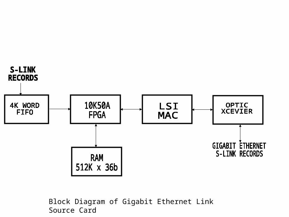
Block Diagram of Gigabit Ethernet Link Source Card

Photograph of Gigabit Ethernet Link Source Card

Configuration of the Gigabit Ethernet Link Source Card
1. Since the FPGA is a configurable device, and the MAC is largely configured by the register contents, the Gigabit Ethernet LSC can function very differently in different applications. Specifications such as latency, internal data storage, etc. depend on the configuration file of the FPGA.
2. Example 1: An S-Link record is received and is written to the input FIFO. As soon as the FIFO goes non-empty the FPGA begins reading S-Link words from the FIFO searching for a header, and as soon as a header is seen the words start being written to the synchronous static RAM. The words are counted as they are written to RAM, the starting address in RAM is written to a table in the EAB, together with an identifying tag, as for example the EventID. When the trailer is encountered writing to RAM is terminated and the word count is written to the table. The FPGA goes back to waiting for the input FIFO top go non-empty. When an Ethernet Frame is received requesting the record identified by the tag, the FPGA formats an Ethernet Frame with the relevant record, and transfers it to the Transmit FIFO of the MAC.

Configuration of the Gigabit Ethernet Link Source Card
3. Example 2: An S-Link record is received and is written to the input FIFO. As soon as the FIFO goes non-empty the FPGA begins reading S-Link words from the FIFO searching for a header, and as soon as a header is seen the words start being written to a FIFO configured in the EAB. The words are counted as they are written to FIFO. When the trailer is encountered writing to FIFO is terminated, and the Ethernet Frame is formatted and shifted to the Transmit FIFO of the MAC, and the FPGA goes back to waiting for the input FIFO top go non-empty.
4. Example 3: An S-Link record is received and is written to the input FIFO. As soon as the FIFO goes non-empty the FPGA begins reading S-Link words from the FIFO searching for a header, and as soon as a header is seen the FPGA formulates the Ethernet Header, transfers it to the Transmit FIFO, and begins transferring the S-Link Record to the Transmit FIFO. When the Control Trailer is seen the FPGA generates the End of Frame.
Testing of the Gigabit Ethernet Link Source Card
1. Drivers to run under Linux supporting operation of the Gigabit Ethernet LSC were written at Argonne, and the card was extensively tested.
S-Link Records were provided by a Rio2, transferred via Gigabit Ethernet to a commercial NIC in the PCI bus of a PC, extracted from the raw Ethernet Frames, and compared to the original records. Data integrity and latency were measured. Subsequently, prototype cards were furnished to the ROS Group in Atlas and to the Electronics Group in LHCb.
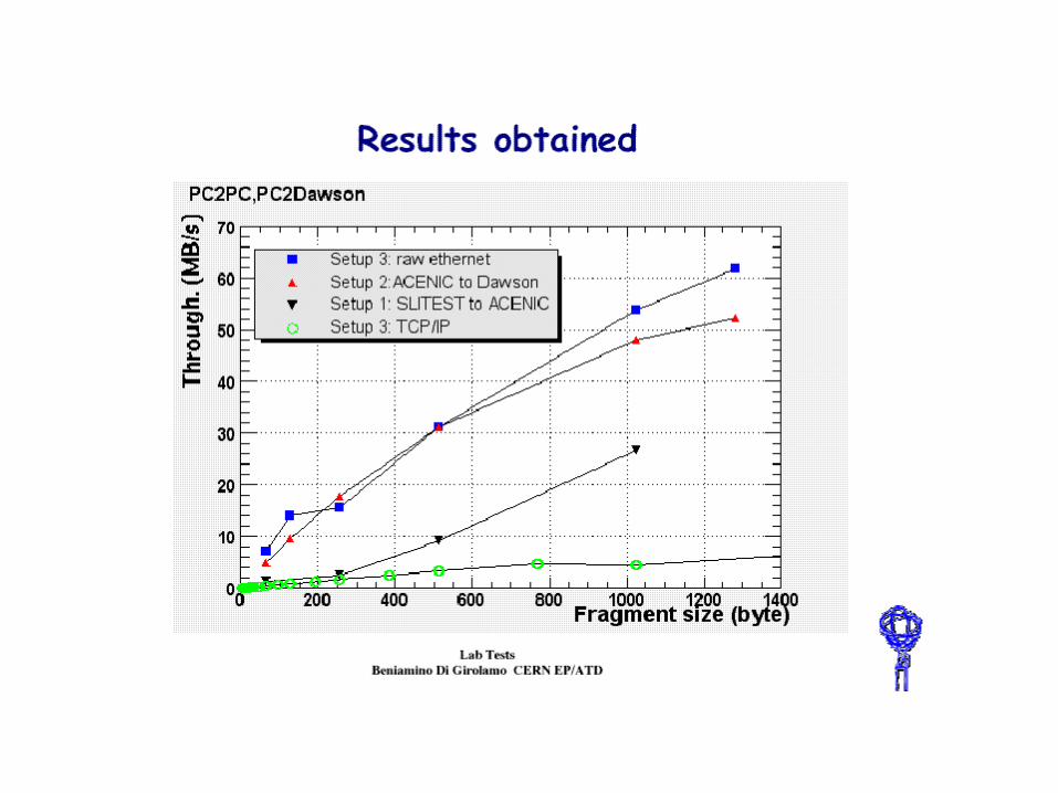

Measured Performance
Using PCI-S-Link Interface Be aware, that PCI will be the limitation. Just a proof of functional compliance, S-Link on one side and
GbE on the other side
Only single word accesses across PCI!
Data from Niko Neufeld
Measured Packet Rate [Hz]
0
100
200
300
400
500
600
700
0 250 500 750 1000 1250 1500
Summary
1. A Link Source Card which accepts standard S-Link records, reformats them as Gigabit Ethernet Frames, and transfers them via fiber has been built and tested at Argonne and CERN.
2. The functioning of the card is determined by configurable logic and may be tailored for widely differing applications.
3. A prototype run has been built and tested. Cards are available to interested persons who would like use them in testbeds or hardware integration studies.
4. A prototype run of cards using copper as the physical medium is being assembled.