a guide to mechanical seals in the electricity...
TRANSCRIPT
• COAL FIRED POWER STATIONS
• NUCLEAR POWER STATIONS
• WATER TREATMENT
• SEAL SELECTION
• CASE HISTORIES
A Guide to Mechanical Seals in the
ELECTRICITY GENERATIONINDUSTRY

EELL
EECC
TTRR
IICCIITT
YYAESSEAL®
ELECTRICITY GENERATION
INDUSTRY
L-UK/US-ELEC-04
IN 4602 - 03/2006
2
Copyright © 2006 AESSEAL plc
AESSEAL plc DisclaimerEXCEPT AS EXPRESSLY PROVIDED HEREIN, AESSEAL plc SHALL NOT BE LIABLE FOR THEBREACH OF ANY WARRANTY, EXPRESS OR IMPLIED, INCLUDING WITHOUT LIMITATIONANY WARRANTY OF MERCHANTABILITY OF FITNESS FOR A PARTICULAR PURPOSE, ORFOR ANY DAMAGES OR OTHER LIABILITY ARISING OUT OF OR IN CONJUNCTION WITHCUSTOMERS’ USE OF SUPPLIER PRODUCTS OR AESSEAL plc OR THE AUTHORISEDDISTRIBUTOR DESIGNING, MANUFACTURING OR SELLING SUPPLIER PRODUCTS. IN NOEVENT SHALL AESSEAL plc BE LIABLE FOR DIRECT, SPECIAL, INCIDENTAL ORCONSEQUENTIAL DAMAGES, INCLUDING WITHOUT LIMITATION LOST SALES OR PROFIT,LOST PRODUCTION OR OUTPUT, INJURY TO PROPERTY OR REPUTATION, OR ANY OTHERDAMAGES WHETHER ARISING IN CONTRACT OR TORT OR OTHERWISE (WHETHER ORNOT ATTRIBUTABLE TO THE FAULT OR NEGLIGENCE OF AESSEAL plc). UNDER NOCIRCUMSTANCES SHALL ANY RECOVERY OF ANY KIND AGAINST AESSEAL plc BEGREATER IN AMOUNT THAN THE PRICE OF THE PRODUCT TO THE END USER.
This information corresponds to our current knowledge on the subject. It is offered solely to providepossible suggestions for your own experimentation. It is not intended, however, to substitute any testingyou may need to conduct to determine for yourself the suitability of our products for your particularpurposes. This information may be subject to revision as new knowledge and experience becomesavailable. Since we cannot anticipate all variations in actual end-use conditions, AESSEAL plc makesno warranties and assumes no liability in connection with any use of this information. Nothing in thispublication is to be considered as a licence to operate under or a recommendation to infringe any patentright.
We would like to thank Terry Johnson, Martin Lister, Dave Silverwood, Scott Yeo, Charles Lynch andReggie Walker for their contributions to this brochure.
CONTENTSDescription Page
Introduction . . . . . . . . . . . . . . . . . . . . . . . . . . . . . . . . . . . . . . . . . . . . . . . . . . . . . . . .3
Coal Fired Power Stations . . . . . . . . . . . . . . . . . . . . . . . . . . . . . . . . . . . . . . . . . . . .4
Nuclear Power Stations . . . . . . . . . . . . . . . . . . . . . . . . . . . . . . . . . . . . . . . . . . . . . .9
Water Treatment . . . . . . . . . . . . . . . . . . . . . . . . . . . . . . . . . . . . . . . . . . . . . . . . . . . .12
Seal Selection . . . . . . . . . . . . . . . . . . . . . . . . . . . . . . . . . . . . . . . . . . . . . . . . . . . . . .15
Case History Index . . . . . . . . . . . . . . . . . . . . . . . . . . . . . . . . . . . . . . . . . . . . . . . . . .18
Case History Information . . . . . . . . . . . . . . . . . . . . . . . . . . . . . . . . . . . . . . . . . . . . .19

EELL
EECC
TTRR
IICCIITT
YY
Copyright © 2006 AESSEAL plc
AESSEAL®
ELECTRICITY GENERATION
INDUSTRY
L-UK/US-ELEC-04
IN 4602 - 03/2006
3
Introduction
Electricity is an indispensable commodity. It drives our industries and our homes.
To generate electricity we are required to rotate a turbine generator at high speed, whichwe do by the passage and expansion of steam across turbine blades. These blades areattached to a shaft which is connected to an electrical generator.
The steam required to drive the unit is generated in Heat Exchangers, known as boilers.The required heat to convert water into steam can be produced by the combustion of fossilfuels or by nuclear reaction.
Both these methods require the use of large quantities of water.
The water is transported by pumps in many various conditions and the sealing of theseunits is paramount to the running of a power station.
In this paper we will be examining these systems and will put forward reliable, costeffective ideas for the control of this environment.
Typical coal fired power station.
EELL
EECC
TTRR
IICCIITT
YY
Copyright © 2006 AESSEAL plc
AESSEAL®
ELECTRICITY GENERATION
INDUSTRY
L-UK/US-ELEC-04
IN 4602 - 03/2006
4
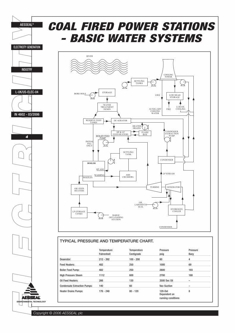
COAL FIRED POWER STATIONS- BASIC WATER SYSTEMS
BORE HOLE
RIVER
STORAGE
SETTLINGTANKS
COOLINGTOWER
LOW HEADSTORAGE
GWS
AUXILLARYCOOLINGWATER
FIRELUB OIL
COOLING
WATERTREATMENT
DEMIN
RESERVE FEEDTANKS
DE AERATOR
HP & LPFEED HEATERS
FLASHBOX
HEATERDRAINS
BOILER FEEDPUMP
INITIALFILL
ONLY
SETTLINGTANK
ASHCRUSHERS
HP ASH
WASHINGNOZZLES
BOILER
OIL FEEDHEATERS
LP STORAGETANKS
BARGEOFF LOADING
STATION
CONDENSEREXTRACTION
PUMP
CONDENSER
LP STREAM
TURBINE GENERATOR
OILLABYRINTH
SEAL
CONDENSER
HYDROGENCOOLER
TYPICAL PRESSURE AND TEMPERATURE CHART.
Temperature Temperature Pressure PressureFahrenheit Centigrade psig Barg
Deaerator: 212 - 392 100 - 200 60 4
Feed Heaters: 482 250 1000 69
Boiler Feed Pump: 482 250 2800 193
High Pressure Steam 1112 600 2700 180
Oil Feed Heaters: 266 130 3500 Sec Oil –
Condensate Extraction Pumps: 140 60 Vac-Suction –
Heater Drains Pumps: 176 - 248 80 - 120 120-Del 8Dependent onrunning conditions

EELL
EECC
TTRR
IICCIITT
YY
Copyright © 2006 AESSEAL plc
AESSEAL®
ELECTRICITY GENERATION
INDUSTRY
L-UK/US-ELEC-04
IN 4602 - 03/2006
5
The systems involved in a Coal Fired Power Station may be split into four basic areas :-
The River Water SystemThe Bore Hole Water SystemThe Condensate SystemThe Auxiliary Systems
THE RIVER WATER SYSTEM
Water is drawn from the river bypumps and deposited insettling tanks to allow anyforeign material such as graveland sand to drop out. The wateris then supplied by pump to thebase of the cooling tower, tomake up for evaporation losses.Alternatively, sea water may beused and circulated back to thesea.
As steam passes through theturbine, it is condensed to formthe main Boiler Feed water. Todo this, it passes through themain Condensers and is cooledby the river water/cooling towercircuit.
Other services supplied by thecooling tower system are (a) thelow head system (b) the GWScircuit (General WaterServices).
The low head system is based on a storage tank and supplies high volume, low pressurewater to the fire fighting system and the cooling of the lubrication oil via the LubricationOil Coolers. This is then re-fed to the main cooling towers.
The General Water Service System is supplied directly from the base of the cooling towersand feeds water to cool the bearings, compressors and fans. This is also re-fed to thecooling towers to complete its circuit.
These two systems are also combined and called Auxiliary Cooling Water Systems in otherPower Stations.
River water is also used to feed the Ash System. This will be described in the AuxiliaryCircuits section.
THE BORE HOLE WATER CIRCUIT
Bore hole pumps are used to draw water from the bore hole and pump water into storage.This is then fed to the Water Treatment plant where the water is demineralised. Thisremoves all mineral contents of the water and prevents the water from forming scale in theboiler when the temperature is elevated and precipitation may occur. From the watertreatment plant, water is supplied to both the Reserve Feed tanks and the Deaerator.
The Reserve Feed tanks are used to initially fill the boiler with cold water, after an outagefor instance, and may be used to ‘make up’ in the Deaerator when required.
CASE No. 1520K
Four AESSEAL® Convertor II™ (70mm) seals werefitted to two Weir vertical split case pumps on aneffluent duty at a power station in 2000 and were stillworking in 2003.

EELL
EECC
TTRR
IICCIITT
YY
Copyright © 2006 AESSEAL plc
AESSEAL®
ELECTRICITY GENERATION
INDUSTRY
L-UK/US-ELEC-04
IN 4602 - 03/2006
6
The Deaerator increases the temperature of the demineralised water and so expels anydissolved oxygen and other gasses. This prevents the forming of acid in the Boiler Feedwater. The deaerated water then passes to the Feed Heaters where the temperature isincreased using a Heat Exchanger and steam from the turbine. Typically, the water wouldbe increased from 90°C(194°F) when it leaves the deaerator to 260°C(500°F) in the FeedHeaters.
The Boiler Feed water is drawn from the Feed Heaters by the Boiler Feed pumps. Thesepumps increase the pressure of the fluid from 1,000 p.s.i.g.(69 bar) at 260°C(500°F) to2,800 psig (193 barg) and supply the boiler.
The boiler increases the temperature to approximately 600°C(1112°F) and this highpressure steam is then fed directly to the turbine. A small pressure drop may be inevidence due to system losses.
THE CONDENSATE SYSTEM
As the steam begins to cool andis passed through the highpressure side of the turbine, it isfed to re-heaters, then re-introduced to the intermediatesection of the turbine and thendirectly to the low pressurearea. A small amount of lowpressure steam is fed to boththe Feed Heaters and Oil FeedHeaters, the rest passes directlythrough the main condensers.The water is cooled asdescribed earlier andtransferred via the CondenserExtraction pumps to theDeaerator to complete theBoiler Feed water closedsystem. The main losses in thissystem come from ‘Blowdown’(disposal of undisolved solids)and ‘Sootblowing’ (steam usedto clean boiler surfaces).
As the steam cools in the heater side of the Feed Heaters after completing its duty, andstarts to condense, it is fed to the flash boxes where the pressure is lowered and hencethe Condensate evaporates. This is then re-fed to the Feed Heaters. When the condensatereaches a temperature too low to evaporate, it is drawn from the flash boxes by the HeaterDrains pumps and passes via the Condensate Return Line to the Deaerators to form a partof the Boiler Feed water.
CASE No. 1521K
Four AESSEAL® 3.875” CURC™ seals with TC/TCfaces were fitted to two Drysdale extraction pumps ata power station in 2000 and were still working in 2003.

EELL
EECC
TTRR
IICCIITT
YY
Copyright © 2006 AESSEAL plc
AESSEAL®
ELECTRICITY GENERATION
INDUSTRY
L-UK/US-ELEC-04
IN 4602 - 03/2006
7
THE AUXILIARY SYSTEMS
(a) Hydrogen is used in the generator as a coolant. To maintain its duty, it is passed throughan auxiliary cooler where Condensate is used to lower its temperature and it is then re-fedto the generator. The Condensate extracts the heat and is passed into the Deaerator FeedLine.
(b) Labyrinth Oil Feed - Thehydrogen is sealed into thegenerator by means of alabyrinth seal at each end of therotor. The rotor labyrinth oilseals are fed with oil at a slightlyhigher pressure than that of thehydrogen by a pumped closedcircuit.
(c) Ash System - The Ashsystem is fed by the river watersupply which is held in astorage tank. Water is then fedto injectors in the base of theboiler by a high pressure feedpump. This flushes the ash fromthe boiler and washes it to theAsh Crushers. The addition ofmore water takes place and asthe crushers rotate the ash isground into a water basedslurry. The slurry is transferredinto Settling Ponds where theash is dropped fromsuspension and the water isreturned to the storage tanks.
CASE No. 1546K
A number of AESSEAL® 3.125” Convertor II™ sealswith Carbon/SiC faces were fitted to Les Blancs RotaryAir pumps at a power station in 1997 and were stillworking in 2003.
CASE No. 1570K
Four AESSEAL® 3.500” Convertor II™ seals withTC/TC faces and Viton® elastomers were fitted to AshCrushers at a power station in 2000 and were stillworking in 2003.

EELL
EECC
TTRR
IICCIITT
YY
Copyright © 2006 AESSEAL plc
AESSEAL®
ELECTRICITY GENERATION
INDUSTRY
L-UK/US-ELEC-04
IN 4602 - 03/2006
8
(d) Fuel Oil Systems - Boiler’start-up’ may be initiated withoil, 3000 to 3500 Sec oil, whichis sprayed into the boiler to aidignition. The oil is pumped fromtankers or barges to lowpressure storage. It is thenpassed through Oil FeedHeaters where the temperatureis increased and the viscositylowered. This is then pumped tothe nozzles in the boiler where itis ignited.
(e) Taprogge Systems - Tomaintain efficiency in HeatExchangers it is important tokeep the water tubes and surfacesfree from scale formation. Scaleis a very efficient insulator. TheTaprogge system is a method ofremoving any scale by pumpingsponge balls around with thewater, some coated with a lightabrasive. This effectivelyremoves any scale build-up inthe system.
Many systems may also belinked to provide back-up coverfor water shortages. The firefighting range may also be fedfrom the bore hole system.
CASE No. 1525K
Twelve AESSEAL® 1.750” CURC™ seals withCarbon/ChOx faces were fitted to KSB pumps on theTapprogee Sytem at a Power Station in 1996 and werestill working in 2003.
CASE No. 1547K
A number of AESSEAL® 40mm SAI™ seals withCarbon/TC faces were fitted to Mirlees AC oil pumpsat a Power Station in 1997 and were still working in2003.

EELL
EECC
TTRR
IICCIITT
YY
Copyright © 2006 AESSEAL plc
AESSEAL®
ELECTRICITY GENERATION
INDUSTRY
L-UK/US-ELEC-04
IN 4602 - 03/2006
9
NUCLEAR POWER STATION(GAS COOLED REACTOR)
In a nuclear power station, a controlled reaction is allowed to take place which in turngenerates heat. The reactor is therefore cooled and this is done by the circulation ofCarbon Dioxide. The heat absorbed is carried by the Carbon Dioxide through a HeatExchanger where the heat is given up to the cooling media - water. The water is convertedto steam and this in turn drives the turbines.
The fluid systems in a nuclear power station can be broken down into three basic sectors:
Treated WaterRaw WaterThe Auxiliary Systems
TREATED WATER
The treated water system is initially fed via the local town mains or a bore hole. This is heldin storage prior to the Water Demineralisation Plant. In this treatment plant, the mineralcontents of the water are removed. This prevents the build up of scale in the boiler as thewater temperature is elevated. Following this treatment, the water is either used to supplythe reserve feed tanks, which may be used to ‘make up’ the boiler feed system via thedeaerator when required, or to initially fill the boiler prior to start up, i.e. after an 'outage'.
The water is supplied to the feed heaters where its temperature is increased, this is doneusing bled steam from the low pressure turbine. The water is now at boiler inlettemperature. As it proceeds to the Deaerator where the temperature of the water isincreased to dispel dissolved gasses since these may become acidic if allowed to enterthe boiler. The boiler feed pumps then transfer the water to the boiler as required.Evaporation then takes place due to the temperature of the incoming Carbon Dioxide fromthe reactor. The steam created is then fed to the high pressure turbine. As the steambegins to cool, it is circulated round re-heaters, then re-introduced to the intermediatesection of the turbine and then directly to the low pressure area. A small amount of lowpressure steam is fed to the Feed Heaters. The rest passes directly through the mainCondenser. Extraction pumps transfer the condensate to the Deaerator to complete theBoiler Feed Water closed system. Main losses in this system come from blowdown andsootblowing.
As the steam cools in the heater side of the Feed Heaters after completing its duty andstarts to condense, it is fed to the flash boxes where the pressure is lowered and hencethe Condensate re-vaporizes. This is then re-fed to the Feed Heaters. When theCondensate reaches a temperature too low to re-vapourise it is drawn from the flash boxesby the Heater Drains pumps and passed via the Condensate Return Line to the Deaeratorsto form part of the Boiler Feed water.
The treated water system also supplies the P.V. cooling system (Pressure Vessel) which isused to cool the structure of the actual reactor via tubing. The water passes through HeatExchangers supplied by the R.C.W. circuit.

EELL
EECC
TTRR
IICCIITT
YYG
EN
. OU
TPU
T66
0 M
We
HY
DR
OG
EN
CO
OL
ER
LA
BY
RIN
TH
OIL
SE
AL
CW
IN
LE
T A
LSO
TO
FIR
E S
YST
EM
DR
UM
SC
RE
EW
ASH
CW
RE
TU
RN
TO
SE
A
RC
WSEA
TU
RB
INE
EX
TR
AC
TIO
NC
ON
DE
NSE
R
BU
FFE
RTA
NK
EX
TR
AC
TIO
NPU
MP
BL
ED
ST
EA
MFR
OM
TU
RB
INE
FEE
DH
EA
TE
RS
RE
SER
VE
FEE
D T
AN
KD
EM
INTA
NK
STO
RA
GE
TO
WN
S M
AIN
PV M
AK
E U
P
DE
AE
RA
TO
R
CO
ND
EN
SER
LP1
LP2
LP3
CO
ND
EN
SAT
E
LP
HP
BO
ILE
RFE
ED
PU
MP
RC
W F
EE
D F
RO
M C
W S
YST
EM
RC
W R
ING
MA
INA
RO
UN
D R
EA
CT
OR
RA
CW
FE
ED
TO
GA
S C
IRC
UL
AT
OR
SFA
NS,
PU
MPS
BE
AR
ING
S
RA
CW
RE
TU
RN
TO
SE
A
HP
STE
AM
RE
-HE
AT
ER
BO
ILE
R GA
SC
IRC
UL
AT
OR
PV
PV CIR
C
PV
RE
AC
TO
RC
OR
E
PV
PV
GA
SC
IRC
UL
AT
OR
PV CIR
C
LO
C
RC
WR
ET
UR
N T
OR
ING
MA
INR
CW
FE
ED
NUCLEAR POWER STATION
Copyright © 2006 AESSEAL plc
AESSEAL®
ELECTRICITY GENERATION
INDUSTRY
L-UK/US-ELEC-04
IN 4602 - 03/2006
10
EELL
EECC
TTRR
IICCIITT
YY
Copyright © 2006 AESSEAL plc
AESSEAL®
ELECTRICITY GENERATION
INDUSTRY
L-UK/US-ELEC-04
IN 4602 - 03/2006
11
RAW WATER SYSTEMS
Raw water may be taken fromthe sea or river, it is screenedand then used on site toperform the basic coolingfunctions. These systemswould typically be:-
C.W: - Cooling Water, firesystem, drumwash pumps etc.R.C.W: - Reactor CoolingWater.R.A.C.W: - Reactor AuxiliaryCooling Water.
C.W.
The prime function of the C.W.system is to feed the maincondensers and remove heatfrom the condensing steam asit leaves the low pressureturbines and dumps the heat towaste. The condensed steam(condensate) then returns tothe boiler feed system.
The C.W. system also suppliesthe fire fighting range and thewater washing system, whichcleans the drum filters on theraw water inlet. The feed for thefollowing systems is also drawnfrom the C.W. water inlet.
R.C.W.
The reactor cooling waterpumps are used via HeatExchangers to cool the P.V.water as it in turn cools thestructure of the reactor. Thewater is drawn from the seaand is returned directly afterthe Heat Exchanger pass.
R.A.C.W.
The Reactor Auxiliary Cooling Water system is used to cool the main gas circulators whichmove the Carbon Dioxide gas around the reactor boiler circuit. This system also cools theother auxiliary equipment such as the fans, pumps and bearings.
THE AUXILIARY SYSTEMS
(a) Hydrogen is used in the generator as a coolant. To maintain it’s duty this is passed throughan auxiliary cooler where Condensate is used to lower it’s temperature. It is then re-fed to thegenerator. The Condensate extracts the heat and is passed into the Deaerator feed line.
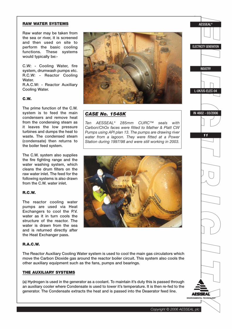
CASE No. 1548K
Ten AESSEAL® 285mm CURC™ seals withCarbon/ChOx faces were fitted to Mather & Platt CWPumps using API plan 13. The pumps are drawing riverwater from a lagoon. They were fitted at a PowerStation during 1997/98 and were still working in 2003.
EELL
EECC
TTRR
IICCIITT
YY
Copyright © 2006 AESSEAL plc
AESSEAL®
ELECTRICITY GENERATION
INDUSTRY
L-UK/US-ELEC-04
IN 4602 - 03/2006
12
(b) Labyrinth Oil Feed - The Hydrogen is sealed into the generator by means of a labyrinthseal at either end of the rotor. The rotor labyrinth oil seals are fed with oil at a slightly higherpressure than that of the Hydrogen by a pumped closed circuit.
WATER TREATMENT SYSTEMSAll water contains impurities. Rain falling through the atmosphere picks up small amounts ofOxygen, Carbon Dioxide and other materials released into the atmosphere by industry.
As rain water contacts the ground, further impurities are dissolved and finally when thestreams form rivers, they receive land drainage, street drainage, sewage and industrialeffluents.
As a result of these processes, many contaminants are present in ‘so called’ water.
All of these impurities can createproblems, fouling treatment plantresins, forming scale in boilersand causing corrosion in coolingsystems.
Contaminants are measured byelectrical conductivity. Examplesof impurity levels are givenbelow:-
Rain water- 50 unitsMoorland water- 150 unitBorehole water - 150 - 800 unitsRiver water - 500 - 2,000 unitsSea water- 50,000 units
The objective of water treatmentin a power station is toneutralise and remove theimpurities to render the water:-
(a) Non-scale forming(b) Non-corrosive(c) Free from dissolved gasses(d) Free from silica
TYPICAL PRESSURE AND TEMPERATURE CHART.
Temperature Temperature Pressure PressureFahrenheit Centigrade psig Barg
Feed Heaters 1 120 49 SaturatedFeed Heaters 2 178 81 SteamFeed Heaters 3 230 110 PressureDeaerators 122 50 60 4Boiler Feed Pump: 345 156 3046 210Carbon Dioxide - Boiler Inlet 1148 620 580 40Carbon Dioxide - Boiler Outlet 577 285 580 40High Pressure Steam 1004 540 2466 170
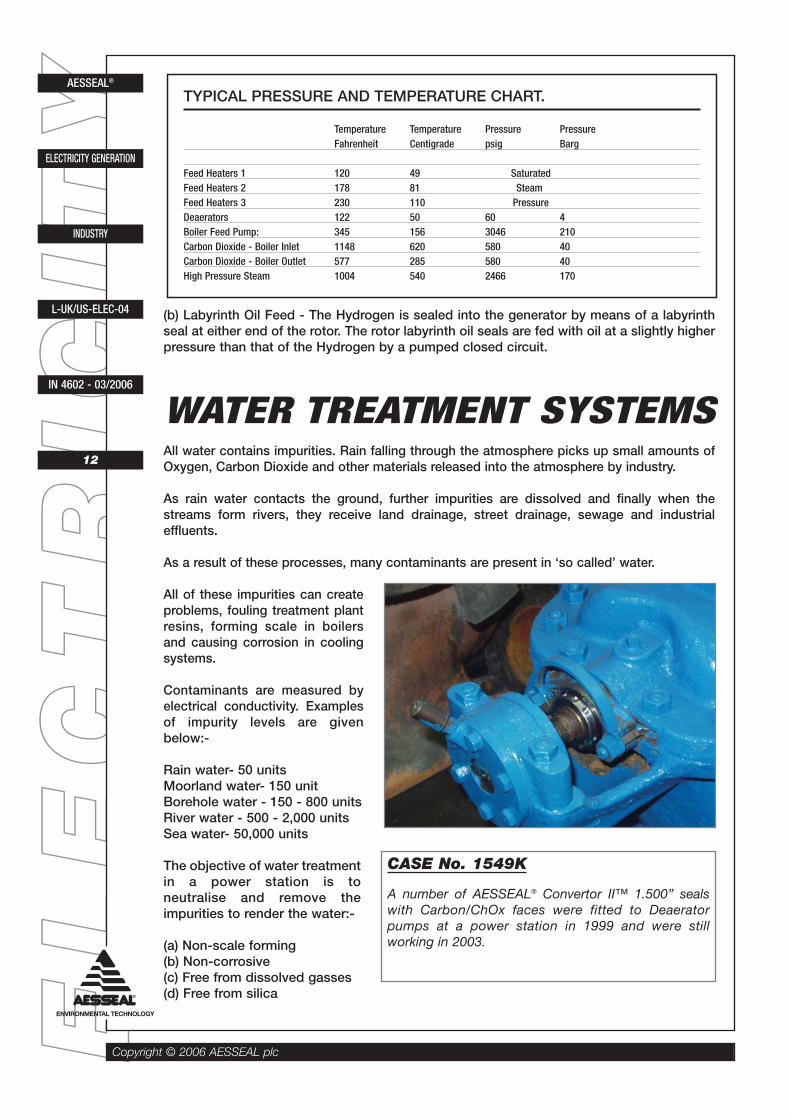
CASE No. 1549K
A number of AESSEAL® Convertor II™ 1.500” sealswith Carbon/ChOx faces were fitted to Deaeratorpumps at a power station in 1999 and were stillworking in 2003.

EELL
EECC
TTRR
IICCIITT
YY
Copyright © 2006 AESSEAL plc
AESSEAL®
ELECTRICITY GENERATION
INDUSTRY
L-UK/US-ELEC-04
IN 4602 - 03/2006
13
Scale forming impurities in the boiler dramatically reduces the efficiency of the boiler asscale is very low in thermal conductivity.
The corrosiveness of water is determined by the impurities present. The materials used tobuild power stations are attacked readily by dissolved acids, Oxygen and salts. Theconsequences of corrosion may be loss of mechanical strength due to thinning of themetal, pitting and perforation of the metallic components and as a consequence, furthercontamination of the water.
The silica level in the water is critical as it will precipitate out in the turbine.
The process of Demineralisation or De-ionisation is carried out in Ion Exchange units,where the active ions that will cause problems are exchanged for non-aggressive ions.
Water is first drawn from bore holes and passed to settling ponds. It is then pumped tohigh level storages from where it is gravity fed through the two Ion Exchange tanks: firstthe Cation Exchange tank and then the Anion Exchange tank.
A typical process exchange would be:-
NaCL O-H Na+CL O-Na H+CLSodiumChloride Cation(Salt) Resin
O-OH H+CL O-CL H20AnionResin
The salt is replaced by water and the Sodium and Chloride ions are trapped with the resinin the exchangers. The exchanger resin is regenerated at set periods, this will be explainedlater.
The water is then passed to a degassing tower to remove the dissolved Carbon Dioxideand finally passed through a Mixed Ion Resin exchanger vessel to polish the water. This isthen stored until it is required in tanks. Upon demand, the water is passed through apolishing unit to remove any scale which may have been picked up in the storage tank. Itis then fed to the Boiler Feed/Condensate system to make up for lost water.
ION EXCHANGE REGENERATION
The Cation Exchanger is regenerated with Sulphuric Acid. The acid supplied is 96% pureand is diluted using a venturi. The addition to the Exchanger is done at 2%. Thisreplenishes the Hydrogen ions in the resin and washes the exchanged ions to waste.
The Anion Exchanger is regenerated with Sodium Hydroxide. This is supplied at 46%concentration and is diluted to 4% for use in the regeneration process. Again theexchanged ions and the excess Sodium Hydroxide are washed to waste.
The waste products are washed into an effluent tank where they are neutralised andpumped to the waste lagoons.

EE LL EE CC TT RR II CC II TT YYCopyright ©
2006 AES
SEA
L plc
AESSEAL®
ELECTRICITY GENERATION
INDUSTRY
L-UK/US-ELEC-04
IN 4602 - 03/2006
14
WATE
RD
E-IO
NIS
ATIO
NP
RO
CE
SS
BOREHOLE
SETTLINGTANK
HIGH LEVELSTORAGE
CATIONEXCHANGE
ANIONEXCHANGE
DE-GASINGTOWER
CO2
EFFLUENTTANK
NEUTRALIZATION
MIXED IONEXCHANGE
POLISIHNG(MIXED ION)
DEMINWATER
STORAGE
ONDEMAND
TOMAKE UP
TO WASTELAGOON
REGENERATIONPROCESS
SULPHURICACID
96%
VENTURIDILUTUION
WITH WATER
SULPHURICACID
2%
SODIUMHYDROXIDE
46%
VENTURIDILUTION
WITH WATER
SODIUMHYDROXIDE
4%

EELLEECCTTRRIICCIITTYY
Copyright ©
2006 AES
SEA
L plc AESSEAL®
ELECTRICITY GENERATION
INDUSTRY
L-UK/US-ELEC-04
IN 4602 - 03/2006
15
Seal selection is based upon the characteristics of the product being sealed. To this end, AESSEAL® select the face combination, 'O' ring materialand seal type specifically for each area.
The drawings on the following pages show the design specified in the selection chart.
The above specifications are the minimum required for the duty specified.
Seal SelectionChemical Temperature Concentration Metallics Face Elastomer Seal Type Alternative Case HistoryBoiler Feed Water (<150ºC) <150ºC (302ºF) 100% AISI 316L C/SiC Aflas® SMSS23™ Plan 23 CDSA™ C/CRO2/CRO2/C/EPR 761H Power GenerationBoiler Feed Water (>150ºC) >150ºC (302ºF) 100% AISI 316L C/SiC Aflas® SMSS23™ Plan 23 DMSF™ Plan 53 C/SiC/SiC/C Power GenerationCaustic Soda AISI 316L TC/TC EPR CURC™ Power GenerationCondensate Extraction <70ºC (158ºF) AISI 316L C/CR02 EPR CURC™ Power GenerationCondensate <70ºC (158ºF) 100% AISI 316L C/CR02 Viton® RDS™ Power GenerationDemineralised Water (120-200ºC) 120-200ºC (248-392ºF) 100% AISI 316L C/TC/CR02/C K4079/K6375/C505 CDSA™ Plan 54, DMSF™ Plan 53 Power GenerationDemineralised Water (0-70ºC) 0-70ºC (32-158ºF) 100% AISI 316L C/CR02 Aflas® CURC™ Power GenerationDemineralised Water (70-120ºC) 70-120ºC (158-248ºF) 100% AISI 316L C/TC Aflas® CURC™ Plan 21 CURE™ Plan 62 Power GenerationFurnace Fuel Oil 71ºC (160ºF) 100% AISI 316L SiC/TC Aflas® SMSR FMG (Steam Quench) Power GenerationHeater Drains 120ºC (248ºF) AISI 316L C/CRO2/CR02/C EPR CDSA™ Power GenerationRaw Material (Ash Plant) <70ºC (158ºF) AISI 316L TC/TC/CRO2/C Viton® CDSA™ Plan 52 Power GenerationRaw Material (Filtered) <70ºC (158ºF) AISI 316L C/CRO2 Viton® CURC™ Power GenerationRaw Material (Unfiltered) <70ºC (158ºF) AISI 316L TC/TC Viton® CURC™ Power GenerationRiver Water 20ºC (68ºF) 100% AISI 316L C/CR02 Viton® CURC™ Power GenerationSea Water <60ºC (140ºF) AISI 316L C/TC Viton® CURC™ 763H Power GenerationSodium Hydroxide Ambient 34% AISI 316L TC/TC EPR CURC™ Power GenerationSodium Thiocyanate (FGD) <100ºC (212ºF) AISI 316L C/SiC/CRO2/C K4079/K6375/C505 CDSA™ Plan 53/54 CURE™ Plan 52 Power GenerationStator Water <70ºC (158ºF) AISI 316L C/CRO2 EPR CURC™ Power GenerationSulphuric Acid Ambient 96% AISI 316L C/SiC/SiC/C V&PTFE Gasket CDSA™ Power GenerationSulphuric Acid Ambient 2% AISI 316L C/SiC/SiC/C Viton® CDSA™ Power GenerationTaprogge 30ºC (86ºF) AISI 316L C/CRO2 Viton® CURC™ Power GenerationWater (Cooling Water Circulation) Ambient AISI 316L C/CRO2 EPR CURC™ Power GenerationWater & Ash 20ºC 20ºC (68ºF) AISI 316L TC/TC Viton® CURC™ Power Generation

EELL
EECC
TTRR
IICCIITT
YYSAI™ - DIN STAT
Convertor II™
CURC™
CURE™
SMSS23™
Copyright © 2006 AESSEAL plc
AESSEAL®
ELECTRICITY GENERATION
INDUSTRY
L-UK/US-ELEC-04
IN 4602 - 03/2006
16
Seal and Systems Selection

EELL
EECC
TTRR
IICCIITT
YY
Copyright © 2006 AESSEAL plc
CRCO™
CDSA™
DMSF™
CONDENSATE SYSTEMS PUMPPAC™
17
IN 4602 - 03/2006
L-UK/US-ELEC-04
INDUSTRY
ELECTRICITY GENERATION
AESSEAL®

EELL
EECC
TTRR
IICCIITT
YY
Copyright © 2006 AESSEAL plc
AESSEAL®
ELECTRICITY GENERATION
INDUSTRY
L-UK/US-ELEC-04
IN 4602 - 03/2006
18
Case HistoriesSeal Type Case Number
Convertor II™ 873, 1520, 1546, 1570, 1549CURC™ 202, 203, 307, 308, 309, 310, 469,
1521, 1525, 1548, 1934MagTecta™ 1614SAI™ 232, 470, 471, 472, 473, 474, 475, 1547, 1932SCUSI™ 1933SMSS™ 1928SMSS23™ 1275, 1929, 1930DMSF™ 1931
Duty
Ash Crushers 1570Condenser Extraction 1521C.W. 1548Deaerator 1549Degassed Water 471Demineralised Water 232Effluent Transfer 472, 1520Fuel Oil 1547Heater Drains 1931Hot Water 1933Mains Water 470, 1929, 1930, 1934River Water 308, 309, 310, 474, 475Regeneration Water 473, 474, 475Sea Water 202, 203, 469Taprogge 1525
Equipment
Allen Gwynne 203Boiler Feed Pump 1928, 1930Blakesborough Strainer 310Drysdale 202, 232, 308, 1521Goodwin 1521Ingersol Rand 1929, 1930KSB 1525Hyco ABB 1932Les Blancs 1546Mather & Platt 309, 1548Mirlees 1547S.P.P. 469Tangye 470, 471, 472, 473, 474, 475Weir (Harland) 1520

EELL
EECC
TTRR
IICCIITT
YY
Copyright © 2006 AESSEAL plc
AESSEAL®
ELECTRICITY GENERATION
INDUSTRY
L-UK/US-ELEC-04
IN 4602 - 03/2006
19
CASE No. 1934KIn a Power Plant in the USA, 2 split case Hyco cooling water pumps were pumping coolingwater at 100 degrees F. 2 x AESSEAL® 1.750" CURCTM mechanical seals with CAR/CROX faces
were fitted in 1999. They were still working in October 2003.
CASE No. 1933KIn a Power Plant in the USA, 2 Unit 1 Hot water coil pumps were pumping Ethylene Glycol andwater at 150 degrees F. 2 x AESSEAL® 1.750" SCUSITM mechanical seals with CAR/TC faceswere fitted in 2000. They were still working in October 2003.
CASE No. 1932KIn a Power Plant in the USA, 5 Hyco ABB Coal Pulveriser pumps were working at 120 degreesF with a cavity pressure of 45 psig. 5 x AESSEAL® 1.250" SAITM mechanical seals with TC/TC/Cfaces were fitted in 1999. They were still working in October 2003.
CASE No. 1931KIn a Power Plant in the USA, 6 Heater Drain Pumps were pumping condensate at 1750 RPMand 365 degrees F. 6 x AESSEAL® 2.500" DMSFTM mechanical seals with C/TC/TC/C faces
were fitted late 2000/early 2001. They were still working in October 2003.
CASE No. 1930KIn a Power Plant in the USA, Ingersoll-Rand CNTA-8 Boiler Feed Pumps were working at 3600RPM with a temperature of 225 degrees F. Two AESSEAL® 2.490" SMSS23TM mechanical seals(Parts number: 3AATC20-E-01C/R01) were installed October 2002 and were still working in
June 2003.
CASE No. 1929KIn a Power Plant in Covington, USA an Ingersoll-Rand CNTA-8 Boiler Feed Pump was movingwater with a temperature between 284 degrees F and 356 degrees F. An AESSEAL® 2.490"SMSS23TM mechanical seal (Stock code: 3AABS20-A-01C/1R01, MaterialsSiC/CAR(Ant)/Aflas/316L, Drawing Number 7115530) was installed in February 2002 and wasstill working in June 2003.
CASE No. 1928KIn a Power Plant in Blair, USA, a Goulds 3700M Boiler Feed Pump was working at 3575 RPMwith a temperature of 280 degrees. The pumps came with competitor seals and coolers.AESSEAL Inc. replaced the competitor seal in November 2002 with an SMSSTM 2.375" CCN
60926 AZA5916ZBA01. The seal was still working in June 2003.
CASE No. 1614KA power plant has upgraded two of its pumps to replace the local labyrinth bush with theAESSEAL® MagTecta™. The labyrinth bush gave periodic problems and resulted in pumpfailure. The pump model is an unknown brand. The size of the MagTecta™ is 2.000" TXS at thepump side and 65mm TXS at the coupling side. Both bearing cover and shaft have beenmodified to suit the standard AESSEAL® MagTecta™. The seals were installed in February andApril 2003 and are working fine.

EELL
EECC
TTRR
IICCIITT
YY
Copyright © 2006 AESSEAL plc
AESSEAL®
ELECTRICITY GENERATION
INDUSTRY
L-UK/US-ELEC-04
IN 4602 - 03/2006
20
CASE No. 1570K
CASE No. 1549K
CASE No. 1548K
CASE No. 1547K
CASE No. 1546K
CASE No. 1525K
CASE No. 1521K
CASE No. 1520K
CASE No. 873H
A power station uses 48 lube oil pumps for both system lubrication and lubricating the whitemetal blower bearings that are sealing reactor gas from atmosphere. There are three pumpsper system, one AC, one DC auxiliary and one AC standby. The lube oil pumps are duplex geartype with an extended stuffing box, with a pressure of approximately 4 bar. Lube oiltemperature is approximately 43°C. Pumps have been fitted with Convertor II™ seals duringshutdown periods, the first some 3 years ago. The customer reports no seal failures to date.
CASE No. 475F
In a power station an AESSEAL® SAI™/DIN stationary, 60mm, with Carbon, Silicon Carbidefaces were installed to Tangye VB 125.400L.04B pumps. The pumps rotate at 1450 r.p.m. andcirculate resin transfer and regeneration water through the water treatment plant. The water isat ambient temperature and 60-80 psig (4-5.5 bar) pressure. The pumps were fitted with theAESSEAL® seals from new and were installed in March 1993. No modifications were required.
CASE No. 469F
In a power station AESSEAL® CURC™ seals, 2.500” with solid Tungsten Carbide faces andViton® ‘O’ rings were installed to S.P.P. CON6 pumps. The pumps rotate at 1400 r.p.m. andcirculate the station GSW cooling water. The sea water is at 160 psig (11 bar) and ambienttemperature. The pumps were previously fitted with single spring seals and these causeddamage to the shaft sleeve. The AESSEAL® seals were installed in early 1995. An adaptor platewas required.
CASE No. 310D
In a power station, AESSEAL® CURC™ seals with Carbon/Chrome Oxide faces and Viton® ‘O’rings were installed in Blakesborough Double Reel Strainers. The strainers rotate at 1rev/minute and remove foreign matter and debris from the main ACW water. The product is atambient temperature and 25 psig (1.7 bar) pressure and contains grit, sand and other smallsolids. The units were previously packed using Graphite/Asbestos packing and had a high leakrate. AESSEAL® CURC™ seals were installed in June 1989. The face of the stuffing box wasre-drilled to accept the seal and an adaptor plate was fitted.
CASE No. 309D
In a power station, AESSEAL® CURC™ seals with Carbon/Chrome Oxide faces and Viton® ‘O’Rings were installed to Mather and Platt Lyrovane pumps. The pumps rotate at 735 r.p.m. andsupply water to the condenser to create a venturi effect, which extracts air from the units. Thewater is at ambient temperature and 20 psig (1.4 bar) pressure. The pumps were previouslypacked using Graphite/Asbestos packing and this needed constant attention. The AESSEAL®
seals were installed in June 1989. No modifications were required.
- Please see page 7
- Please see page 12
- Please see page 11
- Please see page 8
- Please see page 7
- Please see page 8
- Please see page 6
- Please see page 5

EELL
EECC
TTRR
IICCIITT
YY
Copyright © 2006 AESSEAL plc
AESSEAL®
ELECTRICITY GENERATION
INDUSTRY
L-UK/US-ELEC-04
IN 4602 - 03/2006
21
CASE No. 308D
In a power station, AESSEAL® CURC™ seals with Carbon/Chrome Oxide faces and Viton® ‘O’rings were installed in Drysdale Panther pumps. These pumps rotate at 750 r.p.m. and supplylarge quantities of water from the river to the plant. The river water is at ambient temperatureand 30-40 psig (2-2.76 bar). It also contains silt and sand from the river bed. The pumps werepreviously fitted with complicated multi-spring seals which were very difficult to install and somany failures occurred. The AESSEAL® seals were installed in November 1989. An adaptorplate was made against which to mount the seal.
CASE No. 307D
In a power station, AESSEAL® CURC™ seals with Carbon/Chrome Oxide faces and Viton® ‘O’Rings were installed to KSB pumps. The pumps rotate at 1,450 r.p.m. and circulate water andabrasive sponge balls around Heat Exchangers to remove scale and keep the unit efficient.The product is at ambient temperature and 30ft/hd pressure. The water contains abrasiveparticles of scale from the Heat Exchanger tubes. The pumps were previously packed usingvarious materials, all needed constant attention and caused sleeve wear. The AESSEAL® sealswere installed in May 1989. A new extended wear sleeve was fitted to the pump shaft seal andso eliminated the danger of contamination. The flushing water is from a pretreated source.
CASE No. 232C
In a power station, AESSEAL® SAI™/USL seals with Carbon / Chrome Oxide faces and Viton®
‘O’ rings were installed in Drysdale Horizontal Split Case pumps. The pumps rotate at 1,450r.p.m. and extract condensate from the Main Condenser and supply the Deaerator, to be usedas Boiler Feed water. The demineralised water is at 102 psig (7 bar) pressure and 30°C (86°F).The pumps were previously sealed using single spring seals which gave unsatisfactory seallife. The AESSEAL® seals were installed in April 1990. An adaptor plate was made to mount theseal to the stuffing box face.
CASE No. 203C
In a power station, AESSEAL® 3.500" CURC™ seals with Solid Tungsten Carbide faces andViton® ‘O’ rings were installed into Allen Gwynne pumps. The pumps rotate at 1,450 r.p.m. anddraw sea water and circulate it to cool the reactor. The product is at 10°C (50°F) and 30 psig(2 bar). The pumps were previously packed using various packings and due to the abrasivesin the water, i.e. sand, the sleeves wore badly. AESSEAL® CURC™ seals have been installedsince 1985 and give a full service life of two years between the routine maintenance pump re-build. The seals’ bolt slots were deepened to accept the pump bolts P.C.D.
CASE No. 202C
In a power station, AESSEAL® 3.250" CURC™ seals with Solid Tungsten Carbide faces andViton® ‘O’ rings were installed to Drysdale MDC pumps. These pumps rotate at 1,450 r.p.m.and draw sea water into the plant for general cooling. The product is at 10°C (50°F) and 30psig (2 bar). The pumps were previously packed using various types of packing, all givingsevere sleeve wear due to the sand and grit particles in the water. AESSEAL® CURC™ sealswere installed in 1986 and give a full service life of two years, after which the pumps are over-hauled on a routine maintenance scheme. An adaptor plate was manufactured to fit the sealsto the face of the stuffing box.

EELL
EECC
TTRR
IICCIITT
YY
Copyright © 2006 AESSEAL plc
AESSEAL®
ELECTRICITY GENERATION
INDUSTRY
L-UK/US-ELEC-04
IN 4602 - 03/2006
22
NOTE:
Due to AESSEAL® policy of continuous improvement the following seal types have beenupgraded:-
SCI upgraded to SCUSICSAI upgraded to CURCCAPI* upgraded to CURCCAPO upgraded to CRCOCMDS upgraded to CDSA & DMSF
* CAPI does not refer to the current range of AESSEAL plc CAPI API 610 & 682 seals
The original products evolved into more modern seals, which were designed to enhanceapplication performance. The product model reference in the case study is for the mostmodern design, even though at the time of installation the actual installation was theprevious seal model.
All information featured in these case histories has been obtained directly from PlantEngineers.
Although we have confidence in the accuracy of this information, it is not offered as aguarantee for seals manufactured by AESSEAL®.
Any prospective user of our product should verify the information stated to their ownsatisfaction.
Further information is available on all the case histories contained in this booklet uponrequest.
Issue ‘A’ on a case history refers to information which was current on the 31st January1989.
Issue ‘B’ refers to information which was current on 31st January 1990.
Issue ‘C’ refers to information which was current on 31st January 1991.
Issue ‘D’ refers to information which was current on 31st January 1992.
Issue ‘E’ refers to information which was current on 31st January 1993.
Issue ‘F’ refers to information which was current on 31st January 1995.
Issue ‘G’ refers to information which was current on 31st January 1998.
Issue ‘H’ refers to information which was current on 31st October 1999.
Issue ‘I’ refers to information which was current on 31st March 2000.
Issue ‘J’ refers to information which was current on 31st November 2000.
Issue ‘K’ refers to information which was current on 31st March 2003.
Where the statement 'The seals are still working' is made, this means that the customer isor was still using AESSEAL® mechanical seals at the time the case history was updated.This is denoted by either:Issue ‘A’, Issue ‘B’, Issue ‘C’, Issue ‘D’, Issue ‘E’, Issue ‘F’, Issue ‘G’, Issue ‘H’, Issue ‘I’,Issue ‘J’ or Issue ‘K’
For more detailed information, please contact our Applications Department.

EELL
EECC
TTRR
IICCIITT
YY
Copyright © 2006 AESSEAL plc
AESSEAL®
ELECTRICITY GENERATION
INDUSTRY
L-UK/US-ELEC-04
IN 4602 - 03/2006
23

Convertor II™, CURC™, CURE™ CRCO™, CDSA™, CMAX™, CMDA™ DMSF™, SAI™,SMSS™, SMSS23™, SMSR™, AS15™ and SSE10™ are Trademarks of AESSEAL plc Registered Trademarks: AESSEAL® - AESSEAL plcViton® - DuPont Dow Elastomers. Aflas® - Asahi Glass Co. Reference Issue • L - UK/US - ELEC - 04AES / DOC / IN 4602 03/2006
Copyright © 2006 AESSEAL plc
UK Sales & Technical advice:AESSEAL plcMill CloseTempleboroughRotherhamS60 1BZUnited Kingdom
Telephone: +44 (0) 1709 369966Fax: +44 (0) 1709 720788E-mail: [email protected]: http://www.aesseal.com
USA Sales & Technical advice:AESSEAL Inc.10231 Cogdill RoadSuite 105Knoxville, TN 37932USA
Telephone: +1 865 531 0192Fax: +1 865 531 0571E-mail: [email protected]
Systems Sales & Technical advice:AESSEAL (MCK) Ltd.139A Hillsborough Old RoadLisburnN.IrelandBT27 5QE
Telephone: +44 (0) 28 9266 9966Fax: +44 (0) 28 9266 9977Tel/Fax Hotline: +44 (0) 28 9266 9988E-mail: [email protected]
THIS DOCUMENT IS DESIGNED TO PROVIDE DIMENSIONAL INFORMATION AND AN INDICATION OF AVAILABILITY.FOR FURTHER INFORMATION AND SAFE OPERATING LIMITS CONTACT OUR TECHNICAL SPECIALISTS AT THE LOCATIONS BELOW.
Distributed by:
USE DOUBLE MECHANICAL SEALSWITH HAZARDOUS PRODUCTS.ALWAYS TAKE SAFETY PRECAUTIONS:
• GUARD YOUR EQUIPMENT
• WEAR PROTECTIVECLOTHING
WARNING
The AESSEAL® Group of Companies
AESSEAL plc, Rotherham, U.K. Telephone: +44 (0) 1709 369966
AESSEAL plc, Derby, U.K. Telephone: +44 (0) 1332 366738
AESSEAL plc, Peterborough, U.K. Telephone: +44 (0) 1733 230787
AESSEAL plc, Scotland, U.K. Telephone: +44 (0) 1698 540422
AESSEAL plc, Middlesbrough, U.K. Telephone: +44 (0) 1642 245744
AESSEAL plc, Essex, U.K. Telephone: +44 (0) 1708 256600
AESSEAL plc, Pontypridd, U.K. Telephone: +44 (0) 1443 844330
AESSEAL plc, Warrington, U.K. Telephone: +44 (0) 1925 812294
AESSEAL plc, Grimsby, UK. Telephone: +44 (0) 1472 357852
AESSEAL (MCK) Ltd., Lisburn, U.K. Telephone: +44 (0) 28 9266 9966
AESSEAL (MCK) Ltd., Co. Cork, Ireland. Telephone: +353 (0) 214 633477
AESSEAL Inc., Knoxville, Tennessee, USA. Telephone: +1 865 531 0192
AESSEAL Inc., Seneca Falls, New York, USA. Telephone: +1 315 568 4706
AESSEAL Inc., Kingsport, Tennessee, USA. Telephone: +1 423 224 7682
AESSEAL LLC, Cedar Rapids, Iowa, USA. Telephone: +1 319 377 0170
AESSEAL ALAA, Saudi Arabia. Telephone: +966 3 847 3180
AESSEAL Argentina S.A., Buenos Aires, Argentina. Telephone: + 54 11 4744 0022
AESSEAL Australia Pty Ltd. Queensland, Australia. Telephone: +61 7 32791144
AESSEAL Benelux B.V., Breda, Holland. Telephone: +31 (0) 76 564 9292
AESSEAL Brasil Ltda. São Paulo, Brazil. Telephone: +55 11 5891 5878
AESSEAL Canada Inc., Thunder Bay, Ontario, Canada. Telephone: +1 807 624 2727
AESSEAL Chile SA. Providencia Santiago, Chile. Telephone: +56 2 2343022
AESSEAL China Ltd., Ningbo, China. Telephone: +86 (0) 574 8823 2888
AESSEAL Czech s.r.o., Czech Republic Telephone: +42 (0) 543 212 489
AESSEAL Danmark, Køge, Denmark. Telephone: +45 56 64 14 00
AESSEAL Deutschland AG, Rödermark, Germany. Telephone: +49 (0) 6074 881293
AESSEAL Deutschland GMBH, Kronau, Germany. Telephone: +49 7253 8090
AESSEAL Finland OY, Muurame, Finland. Telephone: +358 1433 84500
AESSEAL France S.A.R.L., Nieppe, France. Telephone: +33 (0) 3 2017 2850
AESSEAL Ibérica S.L., Tarragona, Spain. Telephone: +34 977 55 43 30
AESSEAL India PVT. Ltd. Pune, India. Telephone: + 91 20 24220868
AESSEAL Italia SRL., Gallarate, Italy. Telephone: +39 033 179 9952
AESSEAL Malaysia SDN. BHD., Selangor, Malaysia. Telephone: +603 8062 1233
AESSEAL Mexico, S. de R.L. de C.V., Tampico, Mexico. Telephone: (52 833) 214 6983
AESSEAL Polska SP .ZO.O., Bielsko Biala, Poland. Telephone: +48 33 818 4133
AESSEAL Pty Ltd., Confluid Branch, Amanzimtoti, South Africa. Telephone: +27 (0) 31 903 5438
AESSEAL Pty Ltd., Gauteng, South Africa. Telephone: +27 (0) 11 466 6500
AESSEAL SRL Romania, Ploiesti, Romania. Telephone: +40 (0) 244 514891
AESSEAL Turkiye, Istanbul, Turkey. Telephone: +90 (0) 212 659 70 91