mechanical seals - pumpsandsystems.com
TRANSCRIPT

Mechanical Seals

Grundfos Technical Institute www.grundfos.us/training
• Virtual Classroom • Self-Paced • Over 40 courses • Certificates of
Completion • Webinars
• Live and Recorded • Face-to-Face Training
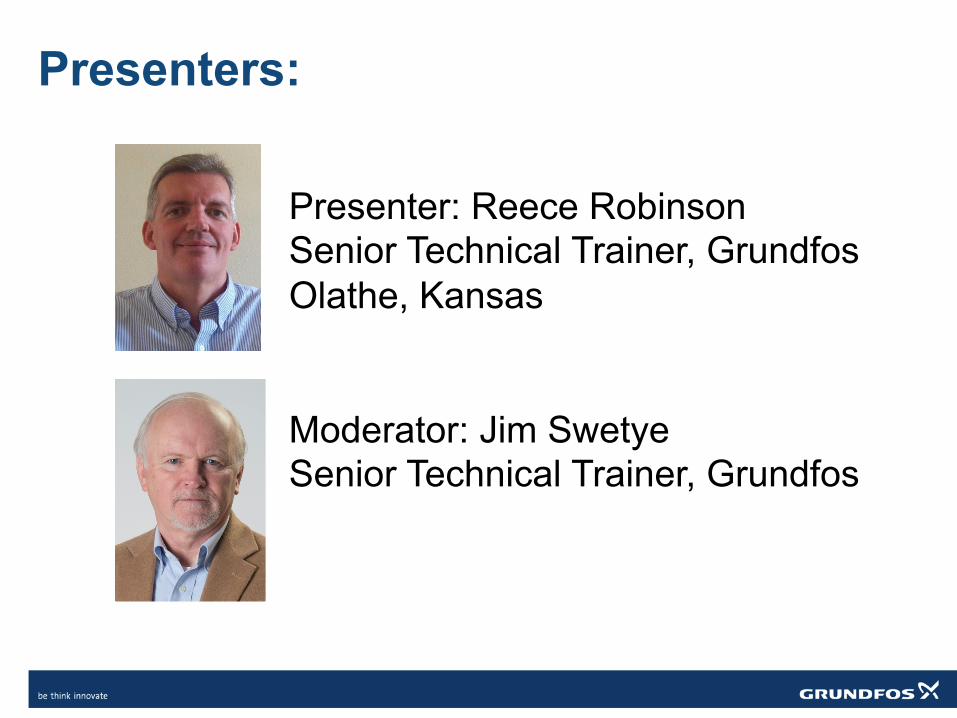
Presenters
Presenter: Reece Robinson Senior Technical Trainer, Grundfos Olathe, Kansas Moderator: Jim Swetye Senior Technical Trainer, Grundfos
Presenters:
Mechanical Seals in the Pump Industry
We will cover this subject in three webinars:
1. Introductory (today) 2. Advanced 3. Installation, service and failure analysis
Course Learning Objectives By the end of this course you will understand and can identify: 1. The purpose of the mechanical seal 2. The essential elements of a mechanical seal 3. The classification of mechanical seals 4. When to use different seal material types 5. Common seal flush plans
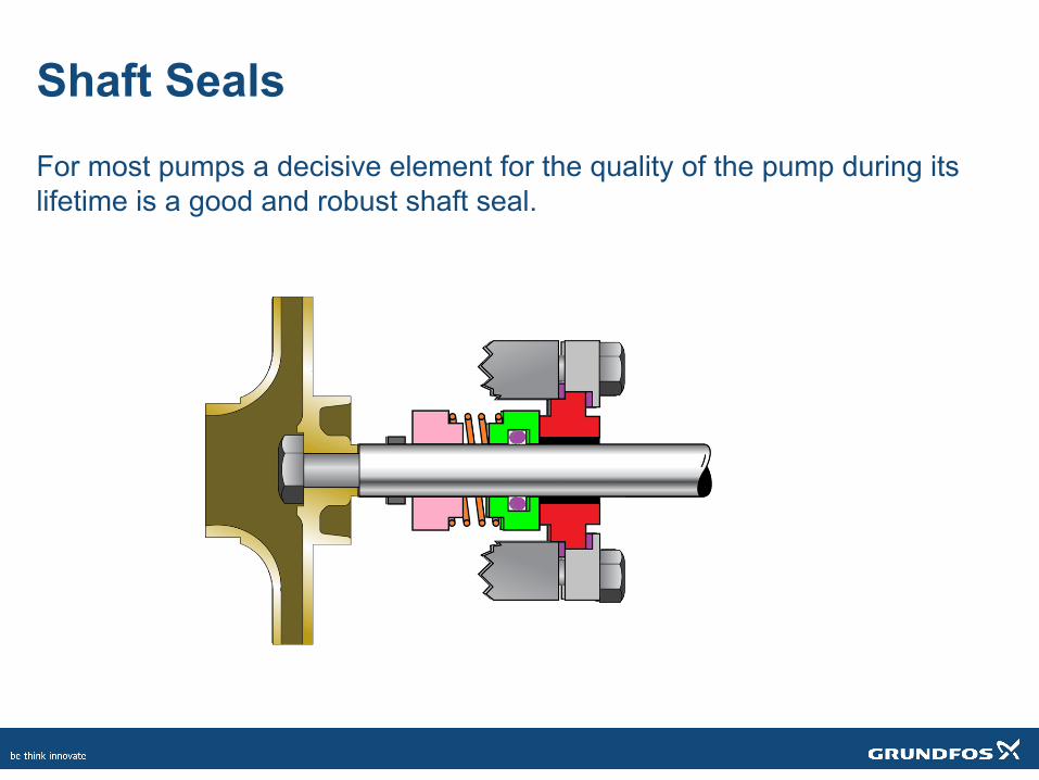
Shaft Seals For most pumps a decisive element for the quality of the pump during its lifetime is a good and robust shaft seal.
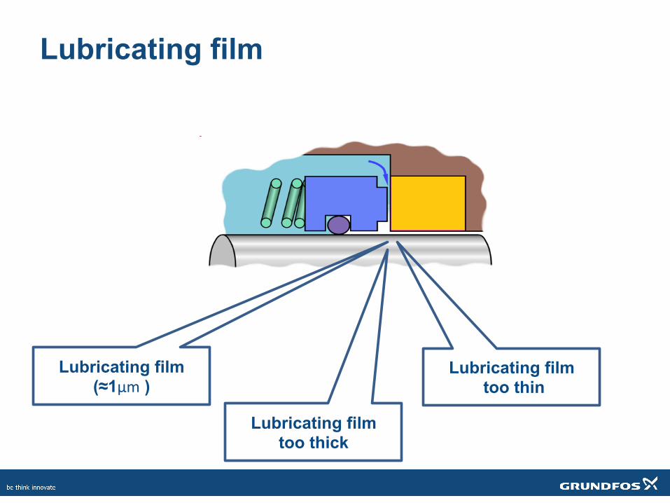
Lubricating film
Lubricating film (≈1µm )
Lubricating film too thick
Lubricating film too thin
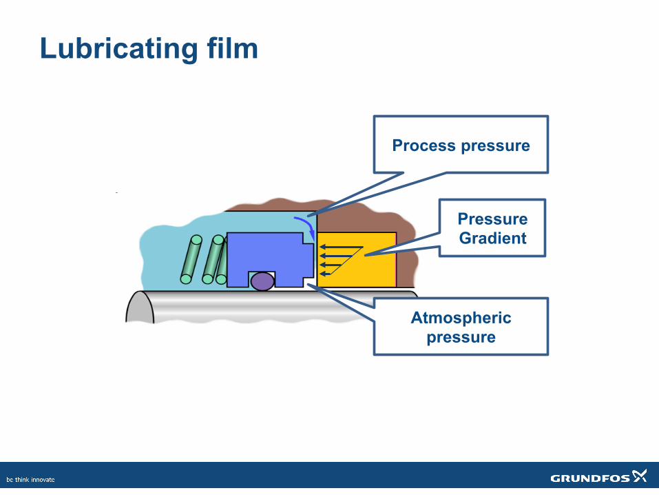
Lubricating film
Process pressure
Atmospheric pressure
Pressure Gradient
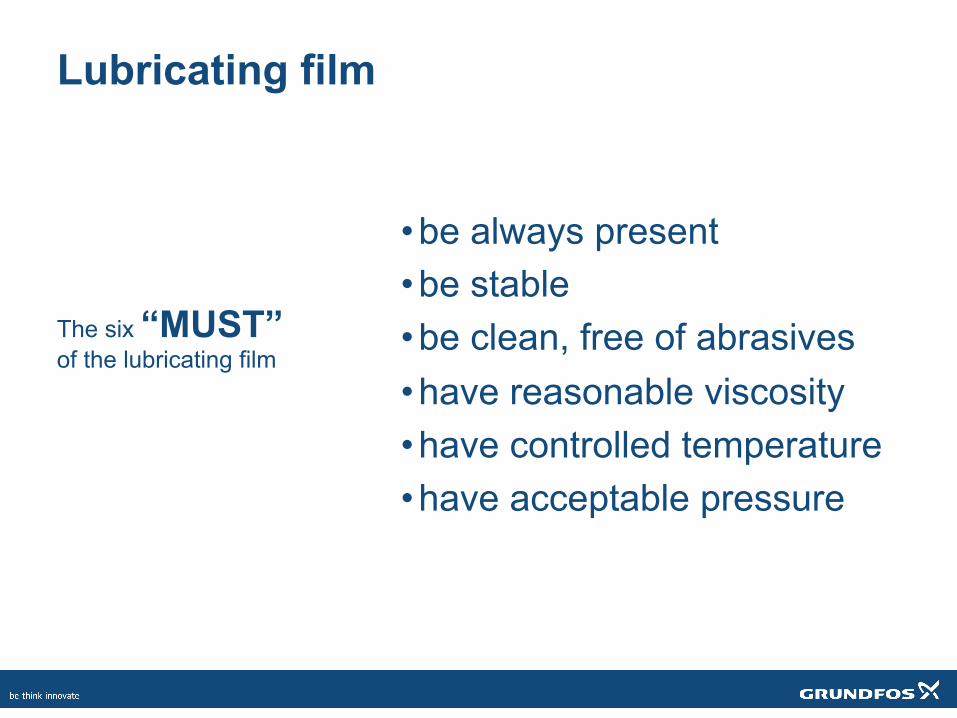
Lubricating film
• be always present • be stable • be clean, free of abrasives • have reasonable viscosity • have controlled temperature • have acceptable pressure
The six “MUST” of the lubricating film
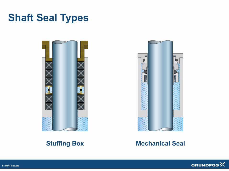
Shaft Seal Types
Stuffing Box Mechanical Seal
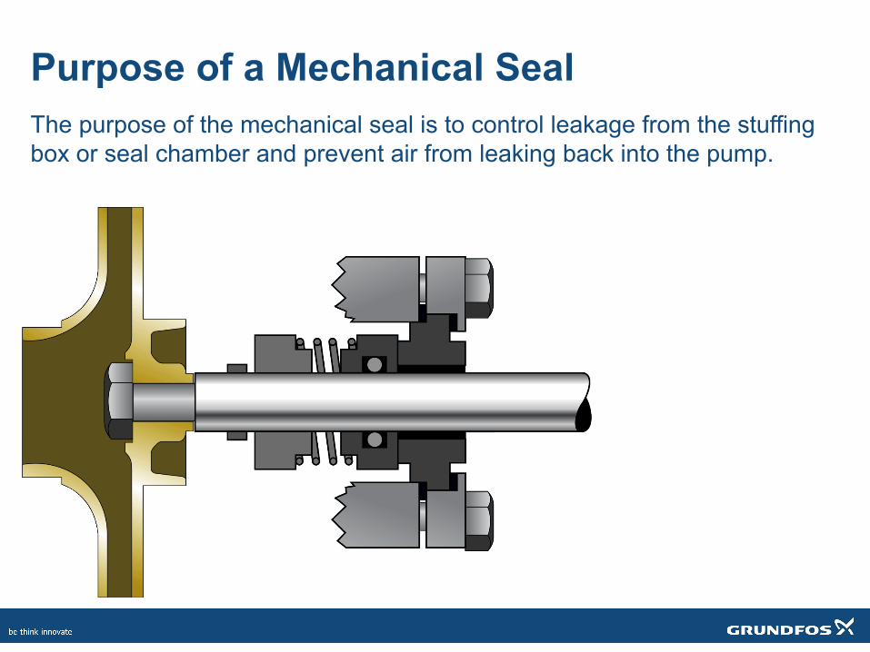
Purpose of a Mechanical Seal The purpose of the mechanical seal is to control leakage from the stuffing box or seal chamber and prevent air from leaking back into the pump.
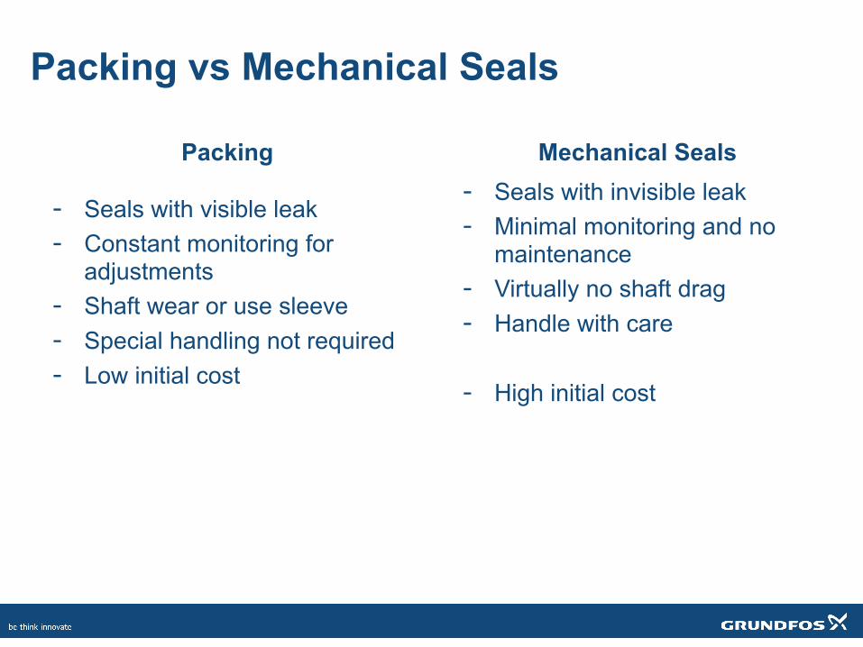
Packing vs Mechanical Seals
Mechanical Seals Packing
- Seals with visible leak - Constant monitoring for
adjustments - Shaft wear or use sleeve - Special handling not required - Low initial cost
- Seals with invisible leak - Minimal monitoring and no
maintenance - Virtually no shaft drag - Handle with care - High initial cost
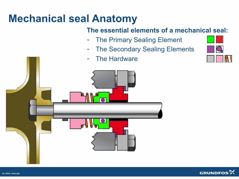
Mechanical seal Anatomy The essential elements of a mechanical seal: - The Primary Sealing Element - The Secondary Sealing Elements - The Hardware
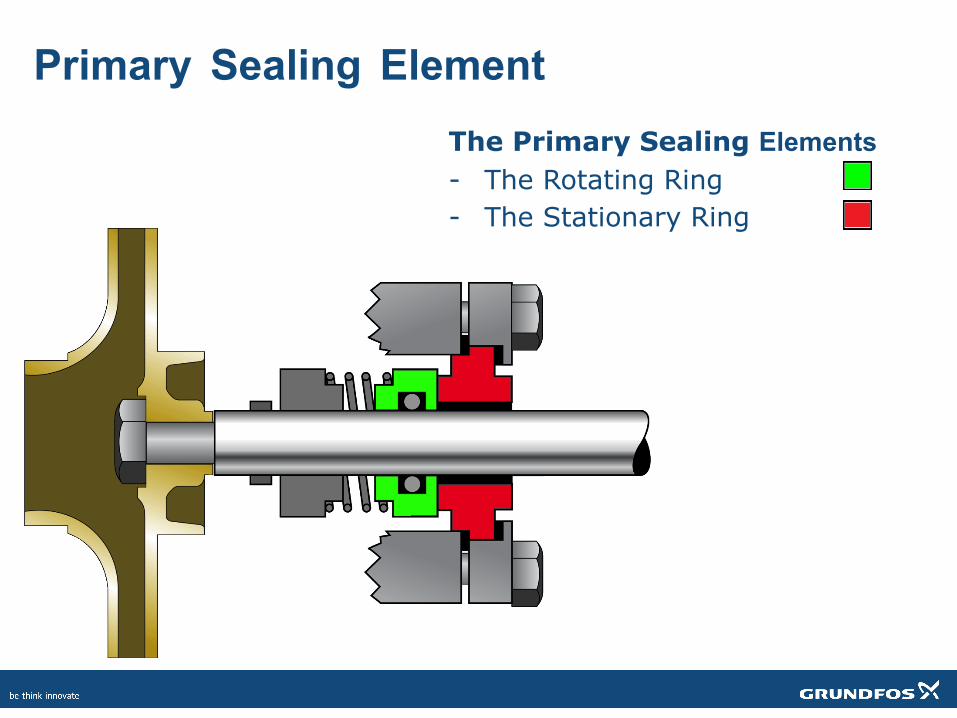
Primary Sealing Element The Primary Sealing Elements - The Rotating Ring - The Stationary Ring
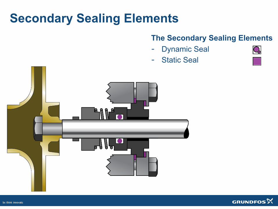
Secondary Sealing Elements The Secondary Sealing Elements - Dynamic Seal - Static Seal
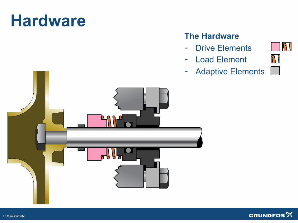
Hardware The Hardware - Drive Elements - Load Element - Adaptive Elements
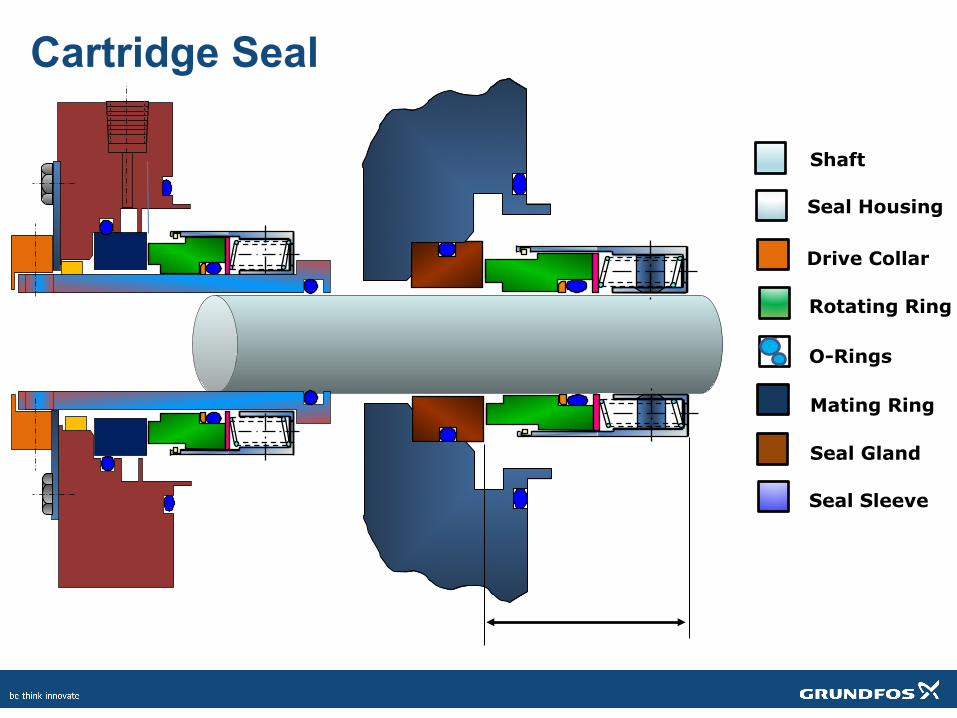
Cartridge Seal
Shaft
Seal Housing
Drive Collar
Rotating Ring
O-Rings
Mating Ring
Seal Gland
Seal Sleeve
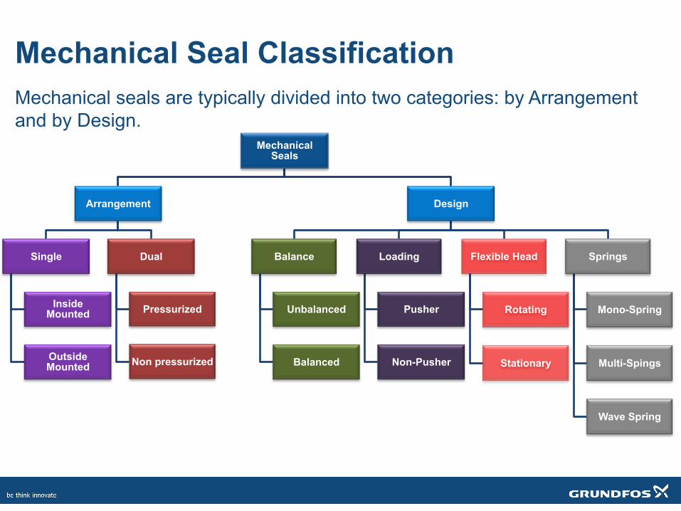
Mechanical Seal Classification Mechanical seals are typically divided into two categories: by Arrangement and by Design.
Mechanical Seals
Arrangement
Single
Inside Mounted
Outside Mounted
Dual
Pressurized
Non pressurized
Design
Balance
Unbalanced
Balanced
Loading
Pusher
Non-Pusher
Flexible Head
Rotating
Stationary
Springs
Mono-Spring
Multi-Spings
Wave Spring
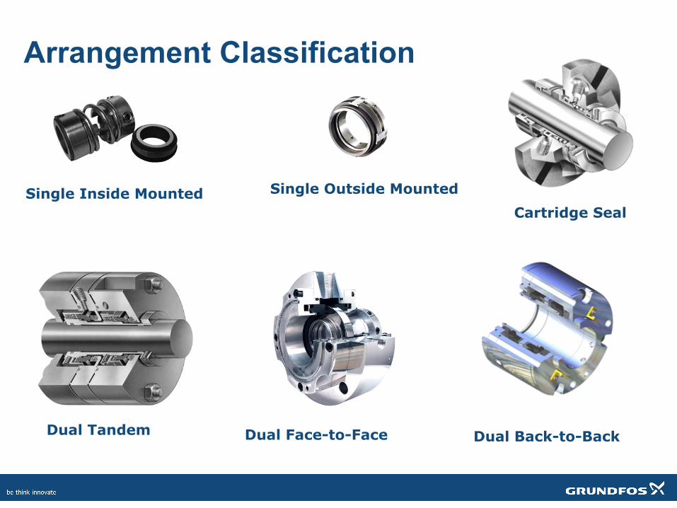
Arrangement Classification
Dual Tandem
Single Inside Mounted Single Outside Mounted Cartridge Seal
Dual Face-to-Face Dual Back-to-Back
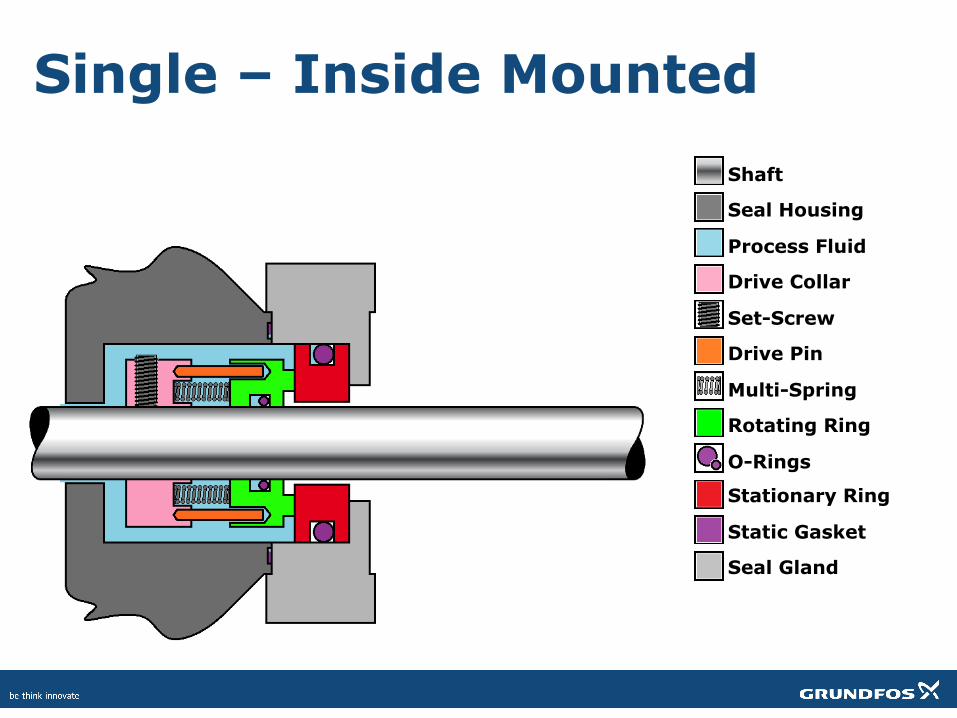
Single – Inside Mounted Shaft
Seal Housing
Process Fluid
Drive Collar
Set-Screw
Drive Pin
Multi-Spring
Rotating Ring
O-Rings
Stationary Ring
Static Gasket
Seal Gland
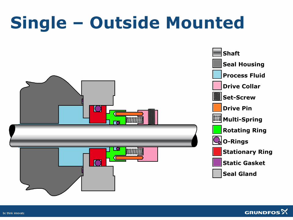
Single – Outside Mounted Shaft
Seal Housing
Process Fluid
Drive Collar
Set-Screw
Drive Pin
Multi-Spring
Rotating Ring
O-Rings
Stationary Ring
Static Gasket
Seal Gland
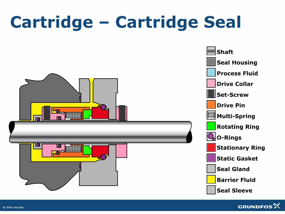
Cartridge – Cartridge Seal Shaft
Seal Housing
Process Fluid
Drive Collar
Set-Screw
Drive Pin
Multi-Spring
Rotating Ring
O-Rings
Stationary Ring
Static Gasket
Seal Gland
Barrier Fluid
Seal Sleeve
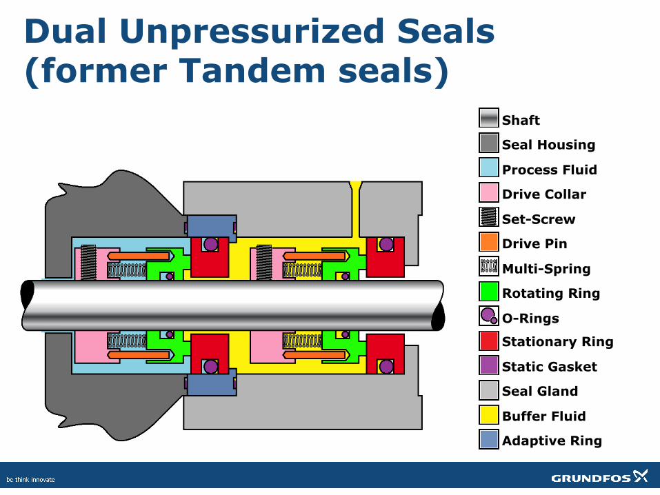
Dual Unpressurized Seals (former Tandem seals)
Shaft
Seal Housing
Process Fluid
Drive Collar
Set-Screw
Drive Pin
Multi-Spring
Rotating Ring
O-Rings
Stationary Ring
Static Gasket
Seal Gland
Buffer Fluid
Adaptive Ring
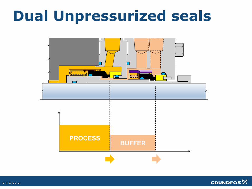
PROCESS BUFFER
Dual Unpressurized seals
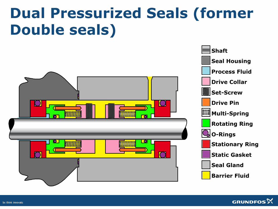
Dual Pressurized Seals (former Double seals)
Shaft
Seal Housing
Process Fluid
Drive Collar
Set-Screw
Drive Pin
Multi-Spring
Rotating Ring
O-Rings
Stationary Ring
Static Gasket
Seal Gland
Barrier Fluid
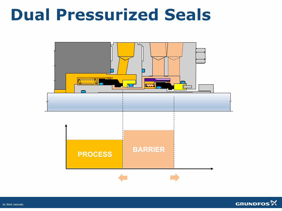
PROCESS BARRIER
Dual Pressurized Seals
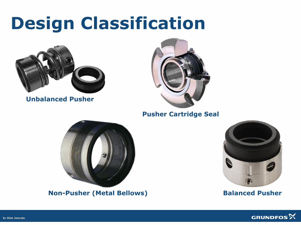
Design Classification
Unbalanced Pusher
Non-Pusher (Metal Bellows)
Pusher Cartridge Seal
Balanced Pusher
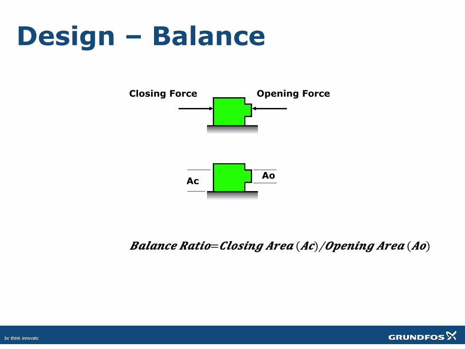
Design – Balance
Opening Force Closing Force
Ao Ac
𝑩𝒂𝒍𝒂𝒏𝒄𝒆 𝑹𝒂𝒕𝒊𝒐= 𝑪𝒍𝒐𝒔𝒊𝒏𝒈 𝑨𝒓𝒆𝒂 (𝑨𝒄)/𝑶𝒑𝒆𝒏𝒊𝒏𝒈 𝑨𝒓𝒆𝒂 (𝑨𝒐)
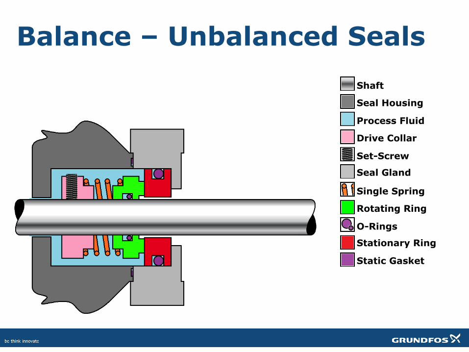
Balance – Unbalanced Seals Shaft
Seal Housing
Process Fluid
Drive Collar
Set-Screw
Single Spring
Rotating Ring
O-Rings
Stationary Ring
Static Gasket
Seal Gland
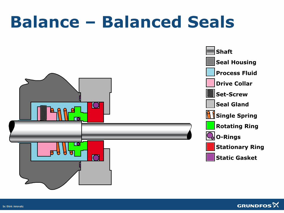
Balance – Balanced Seals Shaft
Seal Housing
Process Fluid
Drive Collar
Set-Screw
Single Spring
Rotating Ring
O-Rings
Stationary Ring
Static Gasket
Seal Gland
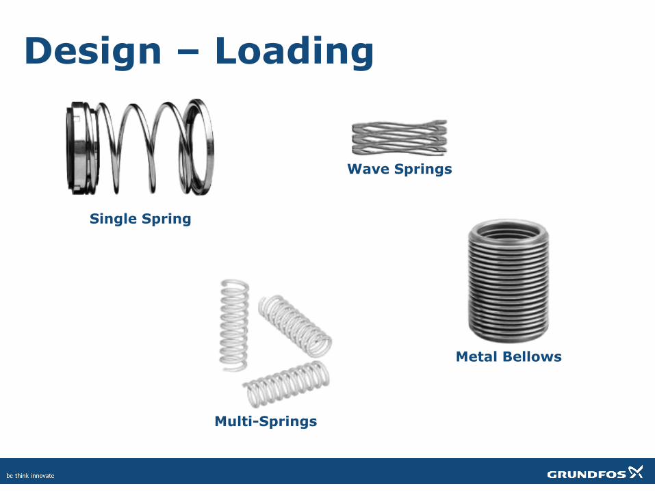
Design – Loading
Single Spring
Multi-Springs
Wave Springs
Metal Bellows
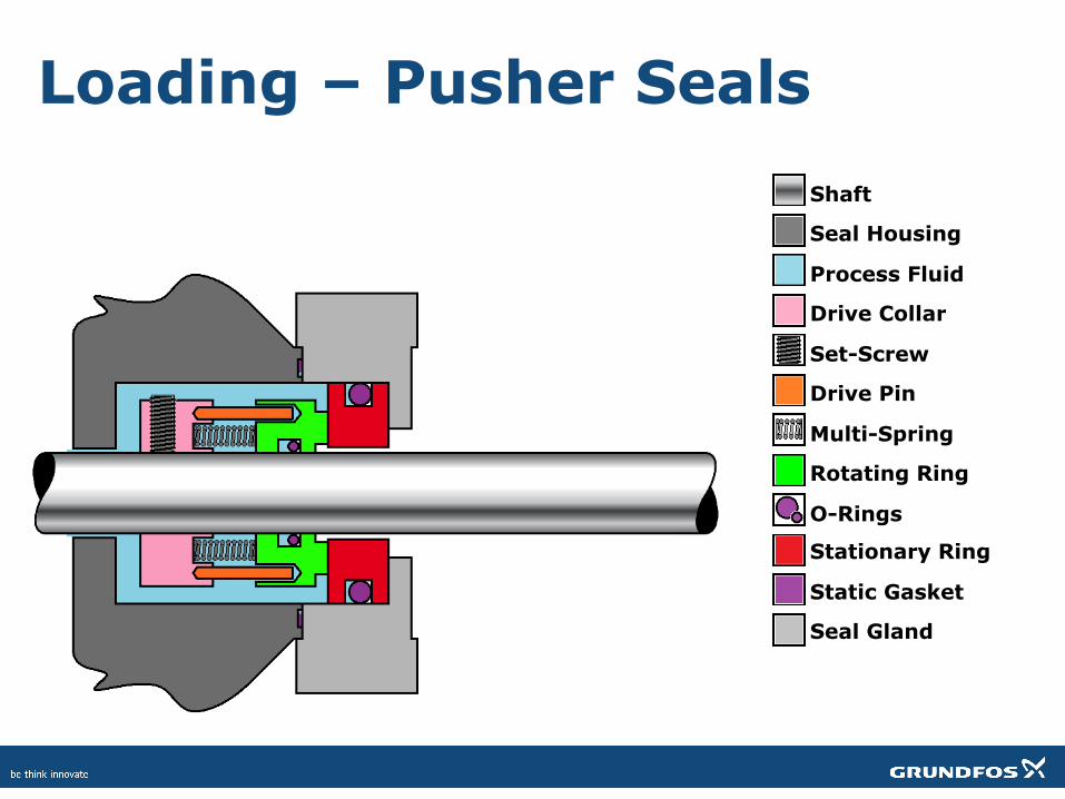
Loading – Pusher Seals Shaft
Seal Housing
Process Fluid
Drive Collar
Set-Screw
Drive Pin
Multi-Spring
Rotating Ring
O-Rings
Stationary Ring
Static Gasket
Seal Gland
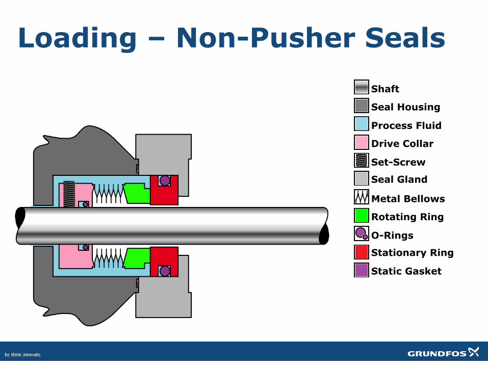
Loading – Non-Pusher Seals Shaft
Seal Housing
Process Fluid
Drive Collar
Set-Screw
Metal Bellows
Rotating Ring
O-Rings
Stationary Ring
Static Gasket
Seal Gland
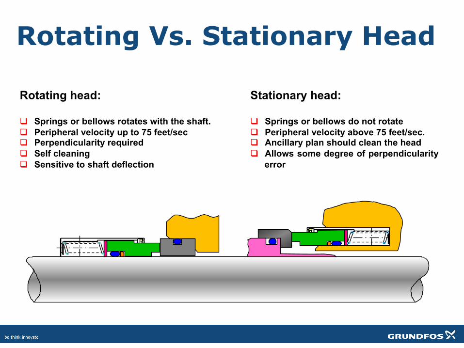
Stationary head: q Springs or bellows do not rotate q Peripheral velocity above 75 feet/sec. q Ancillary plan should clean the head q Allows some degree of perpendicularity
error
Rotating head: q Springs or bellows rotates with the shaft. q Peripheral velocity up to 75 feet/sec q Perpendicularity required q Self cleaning q Sensitive to shaft deflection
Rotating Vs. Stationary Head
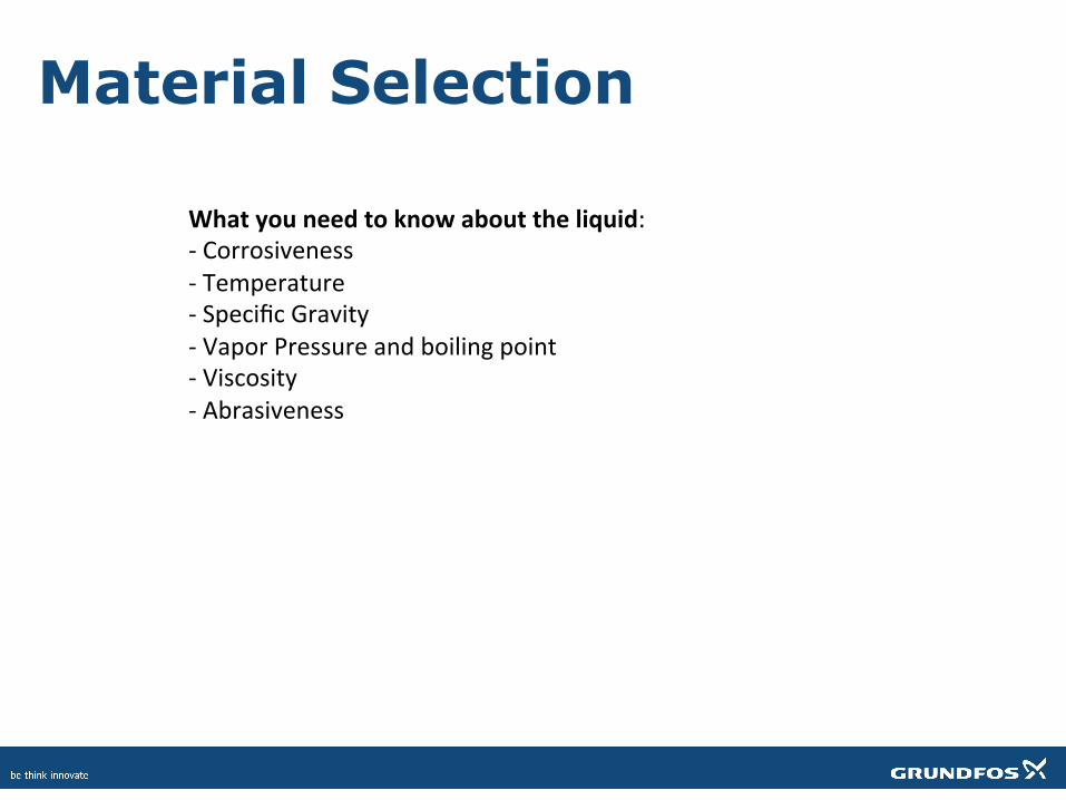
Material Selection
Whatyouneedtoknowabouttheliquid:-Corrosiveness-Temperature-SpecificGravity-VaporPressureandboilingpoint-Viscosity-Abrasiveness
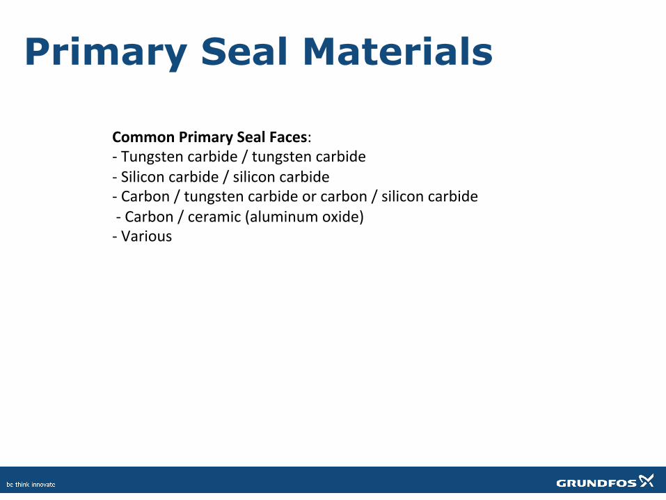
Primary Seal Materials
CommonPrimarySealFaces:-Tungstencarbide/tungstencarbide-Siliconcarbide/siliconcarbide-Carbon/tungstencarbideorcarbon/siliconcarbide-Carbon/ceramic(aluminumoxide)-Various
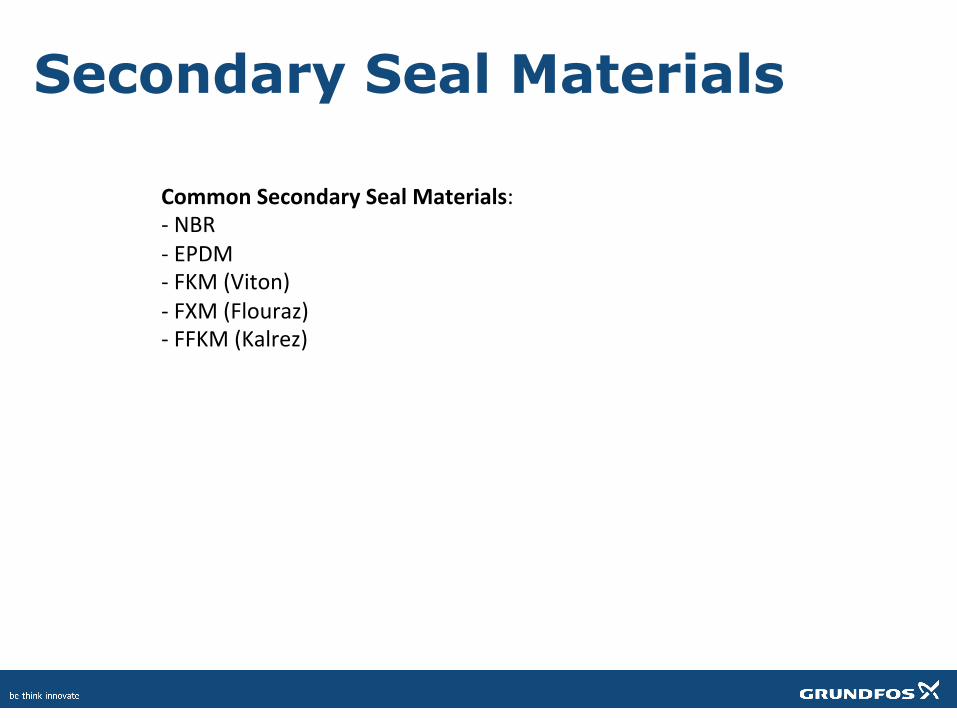
Secondary Seal Materials
CommonSecondarySealMaterials:-NBR-EPDM-FKM(Viton)-FXM(Flouraz)-FFKM(Kalrez)
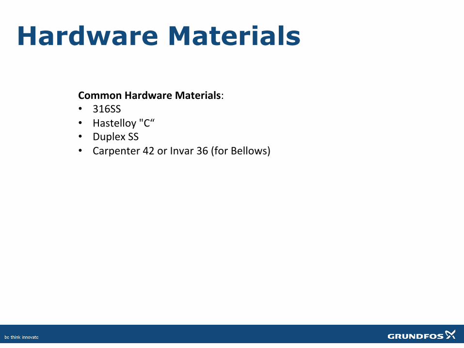
Hardware Materials
CommonHardwareMaterials:• 316SS• Hastelloy"C“• DuplexSS• Carpenter42orInvar36(forBellows)
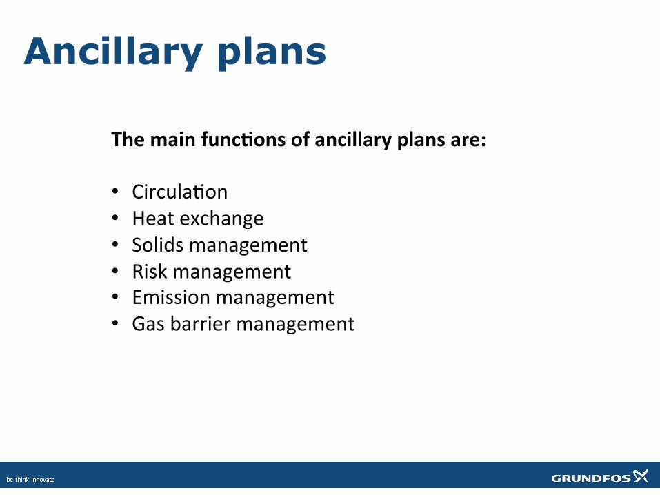
Ancillary plans
Themainfunc>onsofancillaryplansare:• CirculaXon• Heatexchange• Solidsmanagement• Riskmanagement• Emissionmanagement• Gasbarriermanagement
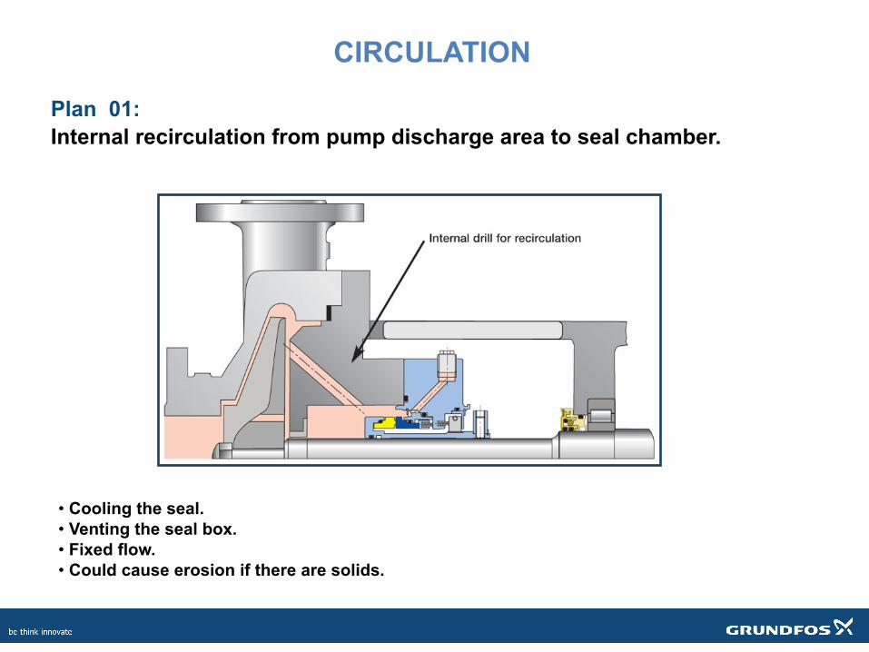
Plan 01: Internal recirculation from pump discharge area to seal chamber.
• Cooling the seal. • Venting the seal box. • Fixed flow. • Could cause erosion if there are solids.
CIRCULATION
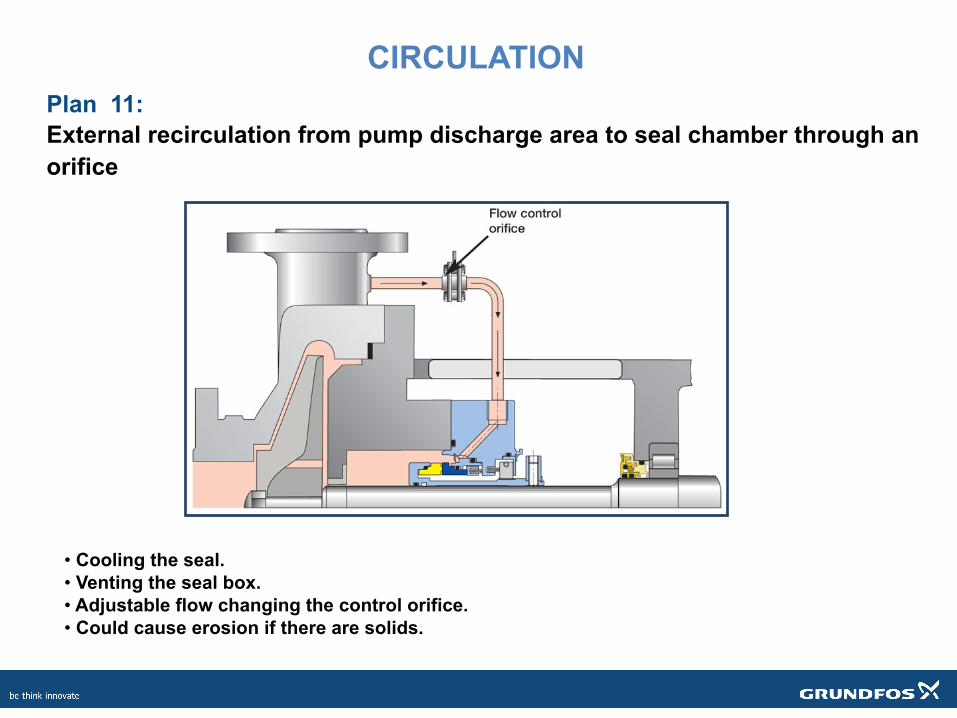
Plan 11: External recirculation from pump discharge area to seal chamber through an orifice
• Cooling the seal. • Venting the seal box. • Adjustable flow changing the control orifice. • Could cause erosion if there are solids.
CIRCULATION
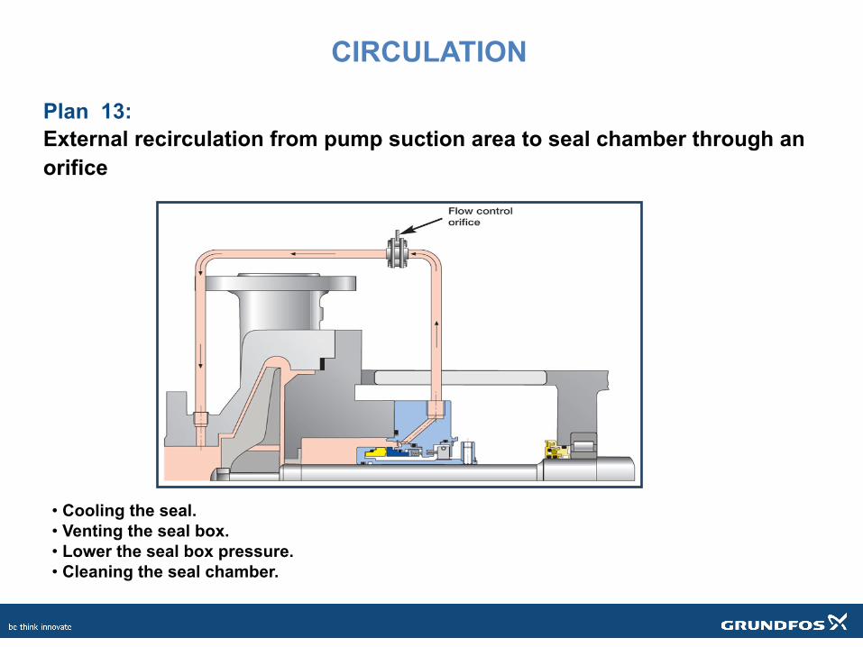
Plan 13: External recirculation from pump suction area to seal chamber through an orifice
• Cooling the seal. • Venting the seal box. • Lower the seal box pressure. • Cleaning the seal chamber.
CIRCULATION
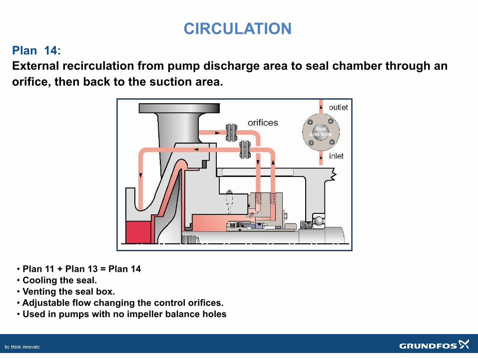
Plan 14: External recirculation from pump discharge area to seal chamber through an orifice, then back to the suction area.
• Plan 11 + Plan 13 = Plan 14 • Cooling the seal. • Venting the seal box. • Adjustable flow changing the control orifices. • Used in pumps with no impeller balance holes
CIRCULATION
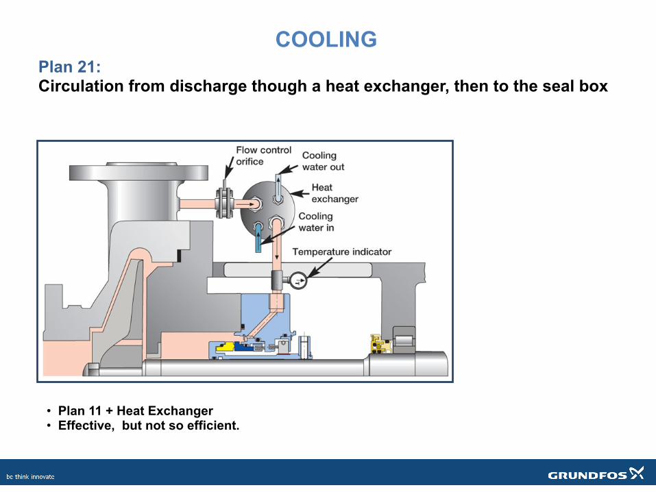
Plan 21: Circulation from discharge though a heat exchanger, then to the seal box
• Plan 11 + Heat Exchanger • Effective, but not so efficient.
COOLING
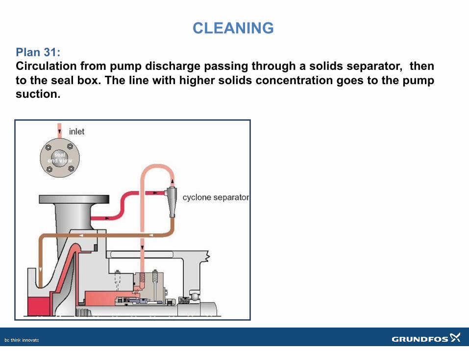
Plan 31: Circulation from pump discharge passing through a solids separator, then to the seal box. The line with higher solids concentration goes to the pump suction.
CLEANING
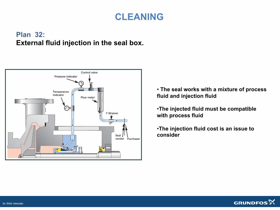
Plan 32: External fluid injection in the seal box.
• The seal works with a mixture of process fluid and injection fluid
• The injected fluid must be compatible with process fluid
• The injection fluid cost is an issue to consider
CLEANING
Course Learning Summary In this course we learned today:1. The purpose of the mechanical seal 2. The essential elements of a mechanical seal 3. The classification of mechanical seals 4. When to use different seal material types 5. Common seal flush plans

Thank you for completing this course!