a low cost high flux solar simulator - mit.educodd/papers/solarsim-2010solarenergy.pdf · a low...
TRANSCRIPT

Available online at www.sciencedirect.com
www.elsevier.com/locate/solener
Solar Energy 84 (2010) 2202–2212
A low cost high flux solar simulator
Daniel S. Codd ⇑, Andrew Carlson, Jennifer Rees, Alexander H. Slocum
Department of Mechanical Engineering, Massachusetts Institute of Technology, 77 Massachusetts Avenue, Cambridge, MA 02139, United States
Received 11 May 2010; received in revised form 24 July 2010; accepted 19 August 2010Available online 16 September 2010
Communicated by: Associate Editor Robert Pitz-Paal
Abstract
A low cost, high flux, large area solar simulator has been designed, built and characterized for the purpose of studying optical meltingand light absorption behavior of molten salts. Seven 1500 W metal halide outdoor stadium lights are used as the light source to simulateconcentrating solar power (CSP) heliostat output. Metal halide bulbs and ballasts are far less costly per-watt than typical xenon arc lampsolar simulator light sources. They provide a satisfactory match to natural sunlight; although ‘unfiltered’ metal halide lights have irra-diance peaks between 800 and 1000 nm representing an additional 5% of measured energy output as compared to terrestrial solar irra-diance over the same range. With the use of a secondary conical concentrator, output fluxes of approximately 60 kW/m2 (60 suns) peakand 45 kW/m2 (45 suns) average are achieved across a 38 cm diameter output aperture. Unique to the design of this simulator, the tiltangle and distance between the output aperture and the ground are adjustable to accommodate test receivers of varying geometry. Use ofoff-the-shelf structural, lighting and electrical components keeps the fabrication cost below $10,000.� 2010 Elsevier Ltd. All rights reserved.
Keywords: Solar simulator; Concentrating solar power; Metal halide lighting; Volumetric receiver; Molten salts
1. Introduction
Solar simulators are invaluable for solar energyresearch. Commercial off-the-shelf simulators are designedto provide small areas of uniform, nearly collimated light,matched to terrestrial solar spectra for photovoltaic (PV)cell testing. Typical flux output intensities are a few ‘suns’(1 sun = 1 kW/m2); thus they do not usually provide thehigh intensities required for concentrating solar power(CSP) testing. Custom made solar simulators have beenbuilt to provide the intensities necessary for CSP research,
0038-092X/$ - see front matter � 2010 Elsevier Ltd. All rights reserved.
doi:10.1016/j.solener.2010.08.007
Abbreviations: CSP, concentrating solar power; FLC, flow line concen-trator; NEMA, National Electrical Manufacturers Association; NREL,National Renewable Energy Laboratory; MH, metal halide.⇑ Corresponding author. Tel.: +1 617 253 1953; fax: +1 617 258 6427.
E-mail addresses: [email protected] (D.S. Codd), [email protected] (A.Carlson), [email protected] (J. Rees), [email protected] (A.H. Slocum).
ranging from 30 to 100 kW/m2 (30–100 suns) and upward,but have cost hundreds of thousands of dollars. Theseresearch simulators utilize high power xenon arc lamps,precision engineered optical elements and active coolingcircuits (Hirsch et al., 2003; Jaworske et al., 1996; Kuhnand Hunt, 1991; Petrasch et al., 2007).
This paper describes the design, development, and test-ing of a low-cost solar simulator, and plans for its con-struction are provided in the Appendix. The goal for thisproject was to design and build a solar simulator for under$10,000 that would offer similar testing capabilities to moreexpensive, high-flux research simulators. The only draw-back is that the light is not well collimated with the simpleconcentrating optics that are employed. Although the unitis designed for CSP thermal testing, specifically to study theabsorption behavior of volumetric molten salt receivers, itcould be utilized for concentrated PV testing provided col-limated light was not needed.
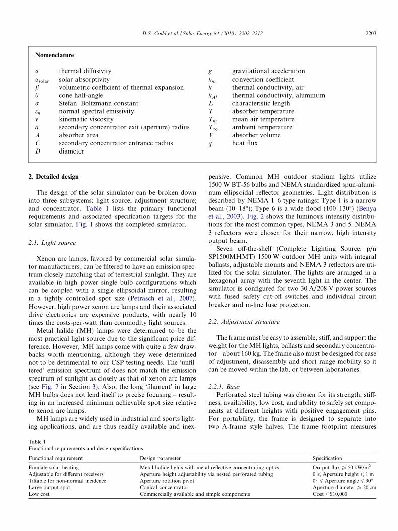
Nomenclature
a thermal diffusivityasolar solar absorptivityb volumetric coefficient of thermal expansionh cone half-angler Stefan–Boltzmann constanten normal spectral emissivitym kinematic viscositya secondary concentrator exit (aperture) radiusA absorber areaC secondary concentrator entrance radiusD diameter
g gravitational accelerationhm convection coefficientk thermal conductivity, airkAl thermal conductivity, aluminumL characteristic lengthT absorber temperatureTm mean air temperatureT1 ambient temperatureV absorber volumeq heat flux
D.S. Codd et al. / Solar Energy 84 (2010) 2202–2212 2203
2. Detailed design
The design of the solar simulator can be broken downinto three subsystems: light source; adjustment structure;and concentrator. Table 1 lists the primary functionalrequirements and associated specification targets for thesolar simulator. Fig. 1 shows the completed simulator.
2.1. Light source
Xenon arc lamps, favored by commercial solar simula-tor manufacturers, can be filtered to have an emission spec-trum closely matching that of terrestrial sunlight. They areavailable in high power single bulb configurations whichcan be coupled with a single ellipsoidal mirror, resultingin a tightly controlled spot size (Petrasch et al., 2007).However, high power xenon arc lamps and their associateddrive electronics are expensive products, with nearly 10times the costs-per-watt than commodity light sources.
Metal halide (MH) lamps were determined to be themost practical light source due to the significant price dif-ference. However, MH lamps come with quite a few draw-backs worth mentioning, although they were determinednot to be detrimental to our CSP testing needs. The ‘unfil-tered’ emission spectrum of does not match the emissionspectrum of sunlight as closely as that of xenon arc lamps(see Fig. 7 in Section 3). Also, the long ‘filament’ in largeMH bulbs does not lend itself to precise focusing – result-ing in an increased minimum achievable spot size relativeto xenon arc lamps.
MH lamps are widely used in industrial and sports light-ing applications, and are thus readily available and inex-
Table 1Functional requirements and design specifications.
Functional requirement Design parameter
Emulate solar heating Metal halide lights with metaAdjustable for different receivers Aperture height adjustabilityTiltable for non-normal incidence Aperture rotation pivotLarge output spot Conical concentratorLow cost Commercially available and s
pensive. Common MH outdoor stadium lights utilize1500 W BT-56 bulbs and NEMA standardized spun-alumi-num ellipsoidal reflector geometries. Light distribution isdescribed by NEMA 1–6 type ratings: Type 1 is a narrowbeam (10–18�); Type 6 is a wide flood (100–130�) (Benyaet al., 2003). Fig. 2 shows the luminous intensity distribu-tions for the most common types, NEMA 3 and 5. NEMA3 reflectors were chosen for their narrow, high intensityoutput beam.
Seven off-the-shelf (Complete Lighting Source: p/nSP1500MHMT) 1500 W outdoor MH units with integralballasts, adjustable mounts and NEMA 3 reflectors are uti-lized for the solar simulator. The lights are arranged in ahexagonal array with the seventh light in the center. Thesimulator is configured for two 30 A/208 V power sourceswith fused safety cut-off switches and individual circuitbreaker and in-line fuse protection.
2.2. Adjustment structure
The frame must be easy to assemble, stiff, and support theweight for the MH lights, ballasts and secondary concentra-tor – about 160 kg. The frame also must be designed for easeof adjustment, disassembly and short-range mobility so itcan be moved within the lab, or between laboratories.
2.2.1. BasePerforated steel tubing was chosen for its strength, stiff-
ness, availability, low cost, and ability to safely set compo-nents at different heights with positive engagement pins.For portability, the frame is designed to separate intotwo A-frame style halves. The frame footprint measures
Specification
l reflective concentrating optics Output flux P 50 kW/m2
via nested perforated tubing 0 6 Aperture height 6 1 m0� 6 Aperture angle 6 90�Aperture diameter P 20 cm
imple components Cost < $10,000
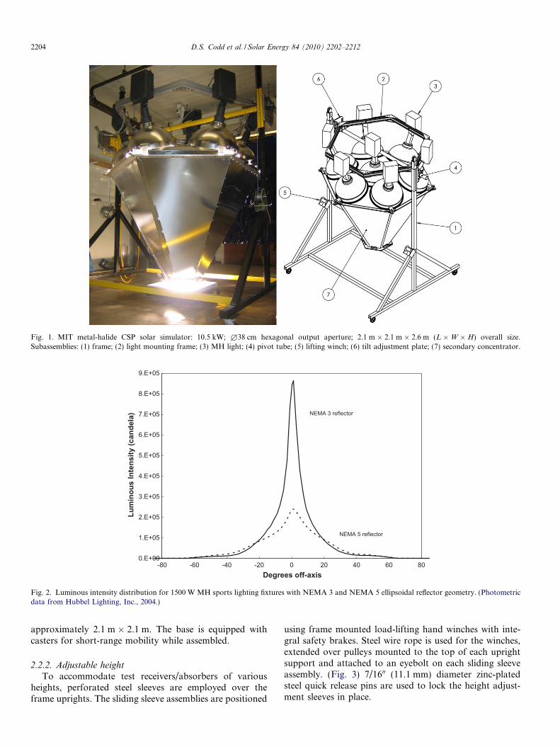
Fig. 1. MIT metal-halide CSP solar simulator: 10.5 kW; £38 cm hexagonal output aperture; 2.1 m � 2.1 m � 2.6 m (L �W � H) overall size.Subassemblies: (1) frame; (2) light mounting frame; (3) MH light; (4) pivot tube; (5) lifting winch; (6) tilt adjustment plate; (7) secondary concentrator.
0.E+00
1.E+05
2.E+05
3.E+05
4.E+05
5.E+05
6.E+05
7.E+05
8.E+05
9.E+05
-80 -60 -40 -20 0 20 40 60 80Degrees off-axis
Lum
inou
s In
tens
ity (c
ande
la) NEMA 3 reflector
NEMA 5 reflector
Fig. 2. Luminous intensity distribution for 1500 W MH sports lighting fixtures with NEMA 3 and NEMA 5 ellipsoidal reflector geometry. (Photometricdata from Hubbel Lighting, Inc., 2004.)
2204 D.S. Codd et al. / Solar Energy 84 (2010) 2202–2212
approximately 2.1 m � 2.1 m. The base is equipped withcasters for short-range mobility while assembled.
2.2.2. Adjustable height
To accommodate test receivers/absorbers of variousheights, perforated steel sleeves are employed over theframe uprights. The sliding sleeve assemblies are positioned
using frame mounted load-lifting hand winches with inte-gral safety brakes. Steel wire rope is used for the winches,extended over pulleys mounted to the top of each uprightsupport and attached to an eyebolt on each sliding sleeveassembly. (Fig. 3) 7/1600 (11.1 mm) diameter zinc-platedsteel quick release pins are used to lock the height adjust-ment sleeves in place.

Fig. 3. Simulator support frame (above) and nestable, perforated squaretubing with pillow block bearing mount for height adjustments (right).Vertical adjustments accomplished with load-lifting winches (2�), locatedon support uprights.
Fig. 4. Rotation adjustment plate attached to MH support assembly,consisting of a steel 200 schedule 40 pipe mounted in pillow-block selfaligning bearings, supporting the hexagonal aluminum extrusion lightsupport structure.
D.S. Codd et al. / Solar Energy 84 (2010) 2202–2212 2205
2.2.3. Rotatable output
The simulator was designed to rotate about a horizontalaxis to enable testing of various CSP receiver designs, somerequiring non-vertical illumination – particularly the caseof glancing angle irradiation over a liquid free-surface.Aluminum extrusions are assembled into a lightweight hex-agonal frame, allowing direct mounting of the six periphe-ral MH light/ballast modules in a compact arrangement toenable pivoting of the entire light assembly.
The hexagonal frame assembly is mounted to a 200 sche-dule 40 (60.3 mm OD � 3.9 mm wall) steel pipe, supportedon both ends by pillow-block mounted bearings. The cen-tral MH light is bolted to a bracket welded directly tothe pipe’s midsection. The pipe and aluminum extrusionswere sized to keep deflection of the frame to a minimum,regardless of the tilt position. Efforts were made to keepthe unit balanced so manual tilt adjustments can be madeeasily. An aluminum adjusting plate was designed to lockthe simulator’s rotation angle at 5� increments, andattached to the pipe with a captive stainless steel torquerod loaded in double shear (Fig. 4). The torque rod servesas a “fuse” yielding to prevent tip-overs at torque of11,800 lb-in (1333 N m), corresponding to a eccentric loadof 380 lb (1.69 kN) applied at the edge of the 6200 (1.6 m)wide light support frame. A single 7/1600 (11.1 mm) diame-ter steel quick release pin locks the angular adjustment.The quick release pins are rated for 13,230 lb (58.8 kN)in single shear, which equates to a maximum load capacityof 3400 lb (15.1 kN) at the outer extremes of the light sup-port frame, more than adequate for the lights and mount-ing structure.
2.3. Secondary concentrator
A simplified secondary concentrator is utilized to boostthe flux available at the output aperture. Designs of non-imaging concentrators are well known – typical designs
are variants of compound parabolic concentrators (CPCs)or flow-line concentrators (FLCs), as shown in Fig. 5 (Win-ter et al., 1991). A truncated FLC was selected for the sim-ulator, resulting in a hexagonal conical structure withreasonable concentration performance that is very simpleto manufacture.
As noted in the design of flat 2-dimensional cone concen-trators, there is a distinct tradeoff between increased con-centration, number of reflections, and the length of theconcentrator. SolTrace, NREL’s ray-tracing freeware, wasused to simulate the optical performance of the secondaryconcentrator. However, the software did not allow for indi-vidual light sources (i.e., the array of seven MH lights) to bedefined, so the entrance plane of secondary concentratorwas illuminated with uniform, collimated input flux. Simu-lated output flux results are shown in Fig. 6 for the conicaldesign geometry, with a 24.9� half-angle. Predicted concen-tration across the output aperture is boosted with notice-ably increased concentration in the center.
Commercial specular reflective ‘bright’ anodized alumi-num (Lorin Industries “ClearBrite�” 1 mm thick 5657-H25 Al) used in custom signs and lighting was chosen forthe concentrator panels for its low cost, low mass andexcellent heat dissipation characteristics. An aluminumframe was fabricated top and bottom for rigidity and easeof attachment to the lights. Additional provisions weremade on the output aperture frame for mounting a hyper-boloidal ‘neck’ to further boost the concentration, ifneeded for future tests. Contoured aluminum adapterplates are used to distribute the stress of the concentratorload without deforming the thin MH primary reflectors,and top ‘filler’ reflectors close the gaps between the MHlights (Fig. 7).
It was assumed that natural convection over the concen-trator’s large outside surface would be sufficient to preventoverheating inside a climate-controlled laboratory environ-ment with ambient temperatures near 25 �C. For example,a worst case calculation of all the input power (10.5 kW)reflected an average of two times over the secondaryconcentrator (assumed reflectivity = 0.89; surface area =4.9 m2) gives a heat flux of only 450 W/m2 – much less thanmidday sun.

θ
z
r
FF
2C
2a
truncate
Fig. 5. Flow-line concentrator geometry; simplified flat-cone constructionalong hyperbolic asymptotes is utilized for the solar simulator. Theasymptotes have a half-angle h relative to the z-axis. Flux aimed between±C will be concentrated onto ±a, resulting in a concentration of C/a (C2/a2 for a hyperboloid of revolution). After Winter et al. (1991).
2206 D.S. Codd et al. / Solar Energy 84 (2010) 2202–2212
During operation, the upper portions of the simulator,including the primary MH light reflectors and the top ofsecondary concentrator, become slightly warm to thetouch. However, during periods of prolonged operationexceeding several hours, the bottom 10 cm of the concen-trator reaches temperatures of 140 �C. This is expected,as there are an increased number of reflections near theoutput aperture and heat from the receiver can conduct
X (m)0-0.05-0.1-0.15
Y (m
)
0.15
0.1
0.05
0
-0.05
-0.1
-0.15
Fig. 6. Output aperture flux concentration ray-tracing simulation results, coconcentrator. 24.9� conical secondary concentrator geometry; 300,000 rays withspot” of over 6� concentration is predicted in the center of the output apertu
into the secondary concentrator. If needed, the concentra-tor’s operating temperature can be reduced by addingexternal finned surfaces or water cooling the distal end ofthe panels, or cooling the output aperture mounting framedirectly.
3. Testing and characterization
After the solar simulator was assembled, the followingtests were performed to determine its suitability for use inour CSP testing: solar spectral match and flux intensitydetermination.
3.1. Spectral distribution
An Ocean Optics USB 650 spectrometer was used tocompare the simulator output from 350 to 1000 nm(VIS–NIR) to midday sun. A pinhole aperture was placedover the sensor to avoid saturating the spectrometer whilecollecting the simulator’s spectra. As shown in Fig. 8, thespectral intensity of the simulator – while not a perfectmatch for sunlight – is a reasonable approximation in therange tested. The NIR intensity peaks typical of MH lightsare clearly visible beyond 800 nm. The MIT CSP simulatordelivers 10.9% of its 350–1000 nm energy in the 800–1000 nm range, as opposed to the sun’s measured 5.9%over the same range.
ConcentrationFactor
6.2735.5764.8794.1823.4852.7882.0911.3940.6970
0.150.10.05
ncentration ratio (output flux/input flux) at exit aperture of secondarya uniform input flux directed parallel to the concentrator’s z-axis. A “hot
re.
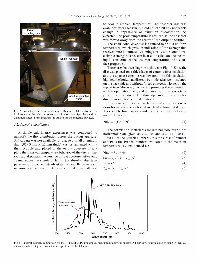
Fig. 7. Secondary concentrator structure. Mounting plates distribute theload evenly on the reflector domes to avoid distortion. Specular anodizedaluminum sheet (1 mm thickness) is utilized for the reflective surfaces.
D.S. Codd et al. / Solar Energy 84 (2010) 2202–2212 2207
3.2. Intensity distribution
A simple calorimetric experiment was conducted toquantify the flux distribution across the output aperture.A flux gage was not available for use, so a small aluminumdisc (£29.3 mm � 1.3 mm thick) was instrumented with athermocouple and placed in the output aperture. Fig. 9plots the transient temperature behavior of the disc at var-ious radial positions across the output aperture. After only20 min under the simulator lights, the absorber disc tem-perature approached steady-state values. Between eachmeasurement run, the simulator was turned off and allowed
300 400 500 600Wavelen
Spec
tral
Inte
nsity
(arb
itrar
y un
its)
MI
Terrestrial solar spectrum
Fig. 8. Spectral intensity comparison for the MIT MH CSP simulator vs. meaintensities when integrated over the test spectrum: 350–1000 nm.
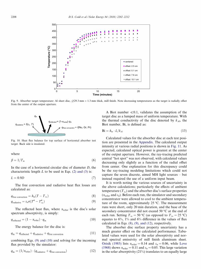
to cool to ambient temperature. The absorber disc wasexamined after each run, but did not exhibit any noticeablechange in appearance or oxidation discoloration. Asexpected, the peak temperature is reduced as the absorberwas moved away from the center of the output aperture.
The small, conductive disc is assumed to be at a uniformtemperature, which gives an indication of the average fluxreceived onto its surface. Assuming steady-state conditions,a simple energy balance can be used to calculate the incom-ing flux in terms of the absorber temperature and its sur-face properties.
The energy balance diagram is shown in Fig. 10. Since thedisc was placed on a thick layer of ceramic fiber insulationand the aperture opening was lowered onto this insulationblanket, the horizontal disc can be modeled as well-insulatedon the back side and without forced convection losses on thetop surface. However, the hot disc promotes free convectionto develop on its surface, and radiates heat to its lower tem-perature surroundings. The thin edge area of the absorberdisc is ignored for these calculations.
Free convection losses can be estimated using correla-tions for natural convection above heated horizontal discs.These can be found in standard heat transfer textbooks andare of the form:
Num ¼ c Gr � Prð Þn ð1Þ
The correlation coefficients for laminar flow over a hothorizontal plate given as c = 0.54 and n = 1/4. (Ozisik,1985) Nu is the Nusselt number, Gr is the Grashof numberand Pr is the Prandtl number, evaluated at the mean airtemperature, Tm and defined as:
Num ¼ hm � L=k ð2ÞGr ¼ gbL3ðT � T1Þ=m2 ð3ÞPr ¼ m=a ð4ÞT m ¼ ðT þ T1Þ=2 ð5Þ
700 800 900 1000gth (nm)
T CSP Simulator
sured midday sun spectra. All curves were normalized to result in identical
0
50
100
150
200
250
300
350
400
450
500
20151050Time (minutes)
Tem
pera
ture
(°C
)
centered
offset: 2.5 cm
offset: 5.1 cm
offset: 7.6 cm
offset: 10.1 cm
Fig. 9. Absorber target temperature: Al sheet disc, £29.3 mm � 1.3 mm thick, mill finish. Note decreasing temperatures as the target is radially offsetfrom the center of the output aperture.
qin
qreflected = (1-αsolar) qinqradiative = f(εn, T )
qfree convection = f(Nu, Gr, Pr)
Fig. 10. Heat flux balance for top surface of horizontal absorber testtarget. Back side is insulated.
2208 D.S. Codd et al. / Solar Energy 84 (2010) 2202–2212
where
b ¼ 1=T m ð6Þ
In the case of a horizontal circular disc of diameter D, thecharacteristic length L to be used in Eqs. (2) and (3) is:
L ¼ 0:9D ð7Þ
The free convection and radiative heat flux losses arecalculated as:
qfree convection ¼ hmðT � T1Þ ð8Þqradiative ¼ enrðT 4 � T 4
1Þ ð9Þ
The reflected heat flux, where asolar is the disc’s solarspectrum absorptivity, is simply:
qreflected ¼ 1� asolarð Þ � qin ð10Þ
The energy balance for the disc is:
qin ¼ qreflected þ qradiative þ qfree convection ð11Þ
combining Eqs. (9) and (10) and solving for the incomingflux provided by the simulator:
qin ¼ ð1=asolarÞ � qradiative þ qfree convectionð Þ ð12Þ
A Biot number �0.1, validates the assumption of thetarget disc as a lumped mass of uniform temperature. Withthe thermal conductivity of the disc denoted by kAl, theBiot number, Bi, is defined as:
Bi ¼ hm � L=kAl ð13Þ
Calculated values for the absorber disc at each test posi-tion are presented in the Appendix. The calculated outputintensity at various radial positions is shown in Fig. 11. Asexpected, calculated optical power is greatest at the centerof the output aperture. However, the ray-tracing predictedcentral “hot spot” was not observed, with calculated valuesdecreasing only slightly as a function of the radial offsetfrom center. One explanation for this discrepancy couldbe the ray-tracing modeling limitations which could notcapture the seven discrete, aimed MH light sources – butinstead required the use of a uniform input beam.
It is worth noting the various sources of uncertainty inthe above calculations; particularly the effects of ambienttemperature (T1) and the absorber disc’s surface properties(asolar and en). Before each run, the simulator and secondaryconcentrator were allowed to cool to the ambient tempera-ture of the room, approximately 25 �C. The measurementruns were short, only 20 min duration, and the base of thesecondary concentrator did not exceed 50 �C at the end ofeach run. Setting T1 = 50 �C (as opposed to T1 = 25 �C)equates to 6%, 1% and 6% difference in the values of fluxcalculated in Eqs. (8), (9), and (12), respectively.
The absorber disc surface property uncertainty has amuch greater effect on the calculated performance. Tabu-lated values were used for the solar absorptivity and nor-mal spectral emissivity of mill finish aluminum sheet.Ozisik (1985) lists asolar = 0.14 and en = 0.06, while Love(1968) shows asolar = 0.11 and en = 0.05. This large variationin the solar absorptivity (21%) translates to an equally large

Fig. 11. Calculated aperture flux distribution, accounting for free convection and radiative losses of the test target. Al sheet disc absorber,£29.3 mm � 1.3 mm thick, mill finish. Heavy solid line corresponds to absorber disc spectral emissivity, en = 0.05, and solar absorptivity, asolar = 0.11(Love, 1968). Bounding dotted lines correspond to en = 0.06, asolar = 0.14 (Ozisik, 1985) and en = asolar = 0.11.
Fig. 12. Schematic of molten salt volumetric receiver for optical heatingtesting with molten nitrate (60/40 Na–K) salts.
D.S. Codd et al. / Solar Energy 84 (2010) 2202–2212 2209
variation in calculated flux. In addition, the spectral outputof the simulator does not match that of the sun exactly, andone would expect a slightly different value for the effective“simulator absorptivity” of the aluminum absorber disc.Because the simulator has additional spectral output inthe near infrared region, the “simulator absorptivity”
should be bounded somewhere between the spectral emis-sivity (NIR–IR) and solar absorptivity (VIS–NIR). Forthis reason, the absorber disc’s nominal values were setto those defined by Love, asolar = 0.11 and en = 0.05.Bounding lines are shown on Fig. 11 for Ozizik’s valuesand the limiting case defined by Kirchhoff’s law:en = asolar = 0.11.
4. Component costs
The costs of the major subassemblies are detailed in thebill-of-materials listed in the Appendix. Direct materialcost for the simulator is under $5000.
5. Molten salt volumetric receiver testing
Preliminary optical heating tests of molten salt receiverswere performed using the MIT CSP Solar Simulator.Figs. 12 and 13 depict the setup, examining the temperaturedistribution of industrial-grade molten nitrate salt (CoastalChemical “Hitec Solar Salt” 60/40 wt.% Na–K NO3 mix-ture; melting temperature 220–240 �C). A well-insulated316L stainless steel receiver, 67 mm inner diame-ter � 250 mm long, was instrumented along its length witheight type K sheathed thermocouples. Four thermocouplesprotrude into the volumetric receiver to measure centerlinetemperatures, while the remaining four are positioned nearthe receiver wall. (Fig. 11) A low expansion, high strengthreinforced silica matrix refractory board (Zircar RSLE-57)with a 63.5 mm aperture was mounted to the bottom of theconcentrator to limit heating to the exposed salt surface.
The salt mixture was premelted, then placed under theMIT CSP solar simulator and optically heated.
The MIT CSP simulator was successful in heating thenitrate salt and keeping it molten. (Fig. 14) Steady-statethermal stratification was observed, although the upper80 mm of the salt was nearly at the same temperature asthe surface. One explanation for this could be the divergentnature of the output rays, as shown in Fig. 15. Due to therelative transparency of the molten salt (Fig. 16), theabsorptive receiver walls are heated selectively in this“fanned-out” upper region, keeping the top hot thicknessgreater than buoyancy effects alone. Further tests areplanned for shallow, wide molten salt receivers that will fillthe entire aperture area.
6. Conclusion and recommendations
A low-cost solar simulator has been developed andtested successfully. It utilizes an array of seven 1500 WMH outdoor sporting lights. With the use of a secondarycone concentrator, output fluxes greater than 60 kW/m2

Fig. 13. MIT CSP solar simulator with molten salt volumetric receiver atbottom.
Fig. 15. Appearance of output rays limited by a 63.5 mm aperture.Clearly visible are the primary (from the MH lights) and secondary(reflected from the concentrator) rays. The non-imaging nature of theconcentrator results in divergent rays as they travel away from theaperture.
Fig. 16. Molten Nitrate (60/40 Na–K) salt mixture in test volumetricreceiver; premelted, then optically heated to 330 �C by MIT CSP solarsimulator – removed for photo. The molten nitrate salt mixture isrelatively transparent to visible light.
2210 D.S. Codd et al. / Solar Energy 84 (2010) 2202–2212
(60 suns) peak and 45 kW/m2 (45 suns) average areachieved across the 38 cm diameter output aperture. Inorder to accommodate test receivers of varying geometry,the simulator’s output aperture height and tilt angle areadjustable. The fabricated cost is kept below $10,000 byextensive use of standard structural, lighting and electricalcomponents.
Although the spectral output of the simulator is shownto be adequate for MIT’s CSP molten salt receiver testingneeds, filters could be placed over the reflector or concen-trator apertures to adjust as needed – accompanied bymore detailed spectrometry in the VIS–NIR–IR spectrum.The use of narrow beam NEMA 1 or custom spun primaryreflectors would be a wise choice for increased outputconcentration; additional benefits could be obtained byadding a contoured hyperboliodal lip to the secondary con-centrator output aperture. Further characterization of out-put irradiance could be performed in accordance withASTM 927, “Standard Specification for Solar Simulationfor Photovoltaic Testing” to classify the simulator for morewidespread use, including concentrated PV testing.
0
0.1
0.2
0.3
0.4
0.5
0.6
0.7
0.8
0.9
1
200 220 240 260 280 300 320 340 360Temperature (°C)
Hei
ght (
x/L)
0 h salt
0 h tank
2.8 h salt
2.8 h tank
8.3 h salt
8.3 h tank
Increasing time
Fig. 14. Temperature distribution of molten nitrate (60/40 Na–K) salt mixture heated by MIT CSP solar simulator.
Appendix A
A.1. Representative flux calculations for the MIT CSP solar simulator
Table A1. Absorber disc properties.
Disc diameter, D (m) Characteristic length, L (m) Ambient temp, T1 (K) asolar en kAl (W/m K)
0.0293 0.0264 298 0.11 0.05 164
Table A2. Calculation of input flux values.
Disc offset from center (cm) Equation from text
0.0 2.5 5.1 7.6 10.2
Steady-state disc temp, T (K) 730 726 704 673 654Tm (K) 514 512 501 486 476 (5)m (m2/s) 3.96E�05 3.93E�05 3.80E�05 3.61E�05 3.49E�05a (m2/s) 5.87E�05 5.84E�05 5.64E�05 5.36E�05 5.20E�05k (W/m K) 4.20E�02 4.18E�02 4.11E�02 4.01E�02 3.95E�02Pr 0.674 0.674 0.673 0.672 0.672 (4)Gr 9.64E+04 9.71E+04 1.01E+05 1.07E+05 1.10E+05 (3)Num 8.62 8.64 8.72 8.84 8.91 (1)hm (W/m2 K) 13.72 13.71 13.61 13.45 13.35 (2)qfree convection (kW/m2) 5.93 5.87 5.52 5.05 4.75 (8)qradiative (kW/m2) 0.78 0.77 0.67 0.56 0.50 (9)qin (kW/m2) 61.0 60.3 56.4 51.0 47.7 (12)Bi 0.0022 0.0022 0.0022 0.0022 0.0021 (13)
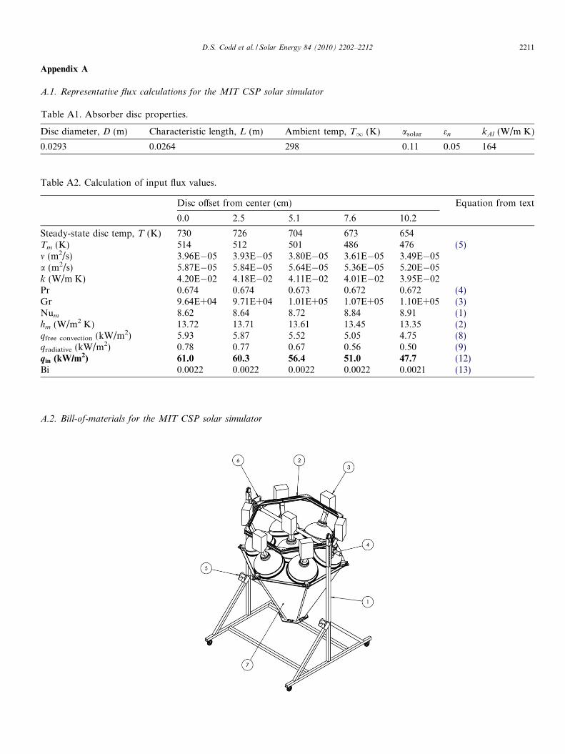
A.2. Bill-of-materials for the MIT CSP solar simulator
D.S. Codd et al. / Solar Energy 84 (2010) 2202–2212 2211

Table A3. Bill-of-materials for the MIT CSP Solar Simulator.
Item No. Name Description Quantity Cost (ea.) Cost (total)
1 Frame assembly Welded steel tubing and casters 1 $280 $2802 Light mounting frame Hexagonal aluminum extrusion assembly 1 $510 $5103 MH light assembly 1500 W MH Stadium Lights with ballasts,
NEMA 3 reflector7 $285 $1995
4 Pivot tube assembly 200 Schedule 40 pipe and pillow block bearings 1 $170 $1705 Winch Load lifting winch and cable accessories 2 $100 $2006 Adjustment plate Aluminum plate (waterjet) for angular adjustment 1 $200 $2007 Concentrator assembly Aluminum (reflective anodized)
concentrator and supports1 $650 $650
- Electrical Wiring, conduit, breaker boxes,disconnect switches, etc.
– – $600
- Hardware Assembly hardware and quickrelease adjustment pins
– – $350
Hardware total: $4955Assembly/fabrication labor: 50 h @ $25/h (direct labor + overhead) total: $1250
Total: $6205
2212 D.S. Codd et al. / Solar Energy 84 (2010) 2202–2212
Acknowledgements
The work presented in this paper is part of an interdis-ciplinary collaboration between the Cyprus Institute, theUniversity of Illinois at Urbana Champaign, the ElectricityAuthority of Cyprus, and the Massachusetts Institute ofTechnology. This work would not have been possible with-out the generous support of the Chesonis Family Founda-tion whose fellowship enabled Daniel Codd to focus onconcentrated solar power research.
References
Benya, J., Heschong, L., McGowan, T., Miller, N., Rubinstein, F., 2003.Advanced Lighting Guidelines. New Buildings Institute, Inc., WhiteSalmon, WA.
Hirsch, D., Zedtwitz, P., Osinga, T., Kinamore, J., Steinfeld, 2003. A new75 kW high-flux solar simulator for high-temperature thermal andthermochemical research. J. Solar Energy Eng. 125 (1), 117–120.
Hubbel Lighting, 2004. Photometric Report, 7-20-2004, CAT NO, TESTNUMBERS: HP-09844 (SLS-1500Hx-x3x), HP-09820 (SLS-1500Hx-x5x). Hubbel Lighting, Inc., Christiansburg, Virginia.
Jaworske, D., Jefferies, K., Mason, L., 1996. Alignment and initialoperation of an advanced solar simulator. J. Spacecraft Rockets 33 (6),867–869.
Kuhn, P., Hunt, A., 1991. A new solar simulator to study hightemperature solid-state reactions with highly concentrated radiation.Solar Energy Mater. 24 (1–4), 742–750.
Love, T.J., 1968. Radiative Heat Transfer. C. E. Merrill Pub. Co.,Columbus, Ohio.
Ozisik, M., 1985. Heat Transfer: A Basic Approach. McGraw-Hill, NewYork.
Petrasch, J., Coray, P., Meier, A., Brack, M., Haberling, P., Wuillemin,D., Steinfeld, A., 2007. A novel 50 kW 11,000 suns high-flux solarsimulator based on an array of xenon arc lamps. J. Solar Energy Eng.129 (4), 405–411.
Winter, C., Sizmann, R., Vant-Hull, L., 1991. Solar Power Plants:Fundamentals, Technology, Systems, Economics. Springer-Verlag,New York.