solar simulator - optical systems and components · ciemat sun simulator (madrid) ... closed...
TRANSCRIPT

Thales SESO S.A.S. Pôle d’Activités d’Aix les Milles 305 rue Louis Armand - CS 30504 13593 Aix-en-Provence Cedex 3 France Tél : 33 (0)4 42 16 85 00 Fax : 33 (0)4 4 216 85 85 E-mail: [email protected]
Issue 2013
Thales SESO S.A.S S.A.S. au Capital de 449 024 € SIRET : 399 064 963 000 16 RCS : Aix en Provence 94 B 1302 APE : 2670 Z – TVA : FR 46 399 064 963
page 2
This document, property of THALES SESO, cannot be used, reproduced or communicated without authorization

page 3
This document, property of THALES SESO, cannot be used, reproduced or communicated without authorization

page 4
This document, property of THALES SESO, cannot be used, reproduced or communicated without authorization

page 5
This document, property of THALES SESO, cannot be used, reproduced or communicated without authorization
Fiche 1 – Form 1
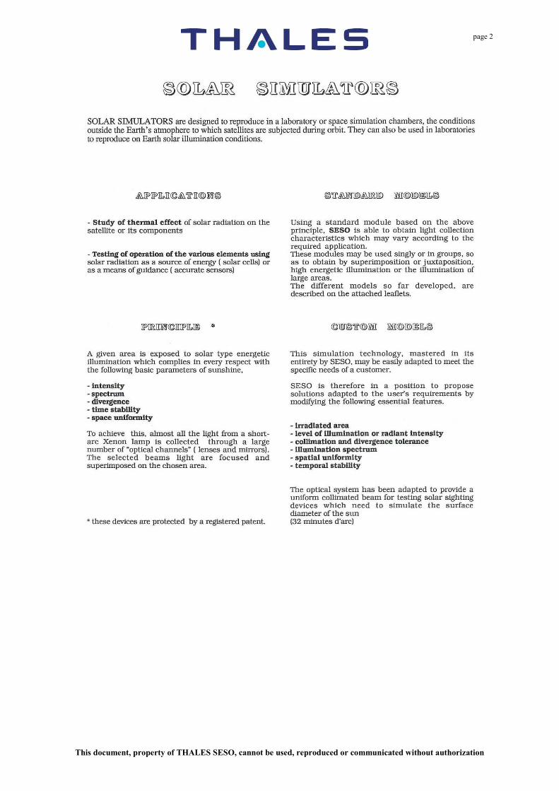
SOLAR SIMULATORS MANUFACTURED BY THALES SESO
THALES SESO
Reference Users
Lamps Power (nbr x power)
Fiche Form
3.24031 CNES – Toulouse (France) 1 x 6.5 KW 2 621.180 AEROSPATIALE – Cannes (France) 1 x 0.7 KW 3 3.24029 INTA – Madrid (Espagne) 1 x 0.7 KW /
2261 CIEMAT – Madrid (Espagne) 3 x 7 KW 6 2534 AEROSPATIALE – Bourges
(France) 10 x 1.2 KW 11
2558 ONERA/CERT (France) 1 x 6.5 KW (UV) 12 2793 SPACEBEL (Belgique) 1 x 2 KW (collimated) / 2821 ESA/ESTEC (Pays Bas) 1 x 2.5 KW 9 2942 AEROSPATIALE – Cannes (France) 1 x 3 KW (collimated) 7 2960 CSL – Liège (Belgique) (collimated) / 3148 ESA/ESTEC (Pays Bas) 1 x 2.5 KW 10 3309 ESA/INTA (Espagne) 1 x 2.5 KW 10 3505 ESA/INTA (Espagne)
Double Beam Simulator 1 x 1.6 KW 1 x 2 KW
/
3738 SEP (France) 10 x 150 W / 3819 CEAT (France) 1 x 2.4 KW (IR) / 3813 ISRO/LEOS (Inde) 1 x 2.5 KW (collimated) 15 3905 CEA/LETI – Grenoble (France) 1 x 2.5 KW 14 3689 CEA/CESTA – Bordeaux (France) 1 x 1 KW / 4146 ISRO-ISAC (Inde) 1 x 3 KW (collimated) 15 4146 ISRO/LEOS (Inde) 1 x 3 KW (collimated) 15 4667 ESA/INTA (Espagne) 3 x 2 KW (collimated) 16
4830-4881 ISRO/LEOS - ISRO/ISAC (Inde) 1 x 3 KW (collimated) 15 Appendix: Scientific Articles
page 6
This document, property of THALES SESO, cannot be used, reproduced or communicated without authorization
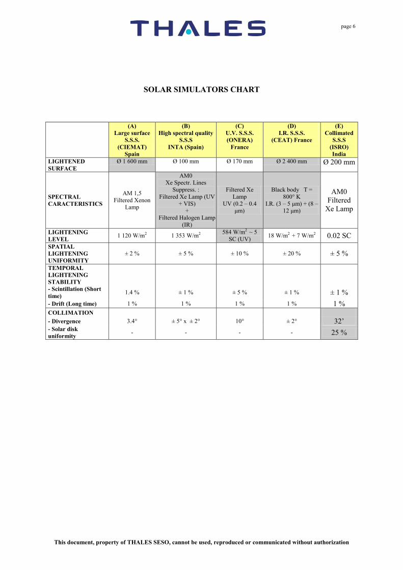
SOLAR SIMULATORS CHART
(A) Large surface
S.S.S. (CIEMAT)
Spain
(B) High spectral quality
S.S.S INTA (Spain)
(C) U.V. S.S.S. (ONERA)
France
(D) I.R. S.S.S.
(CEAT) France
(E) Collimated
S.S.S (ISRO) India
LIGHTENED SURFACE
Ø 1 600 mm Ø 100 mm Ø 170 mm Ø 2 400 mm Ø 200 mm
SPECTRAL CARACTERISTICS
AM 1,5 Filtered Xenon
Lamp
AM0 Xe Spectr. Lines
Suppress. : Filtered Xe Lamp (UV
+ VIS) +
Filtered Halogen Lamp (IR)
Filtered Xe Lamp
UV (0.2 – 0.4 μm)
Black body T = 800° K
I.R. (3 – 5 μm) + (8 – 12 μm)
AM0 Filtered
Xe Lamp
LIGHTENING LEVEL 1 120 W/m2 1 353 W/m2 584 W/m2 ~ 5
SC (UV) 18 W/m2 + 7 W/m2 0.02 SC SPATIAL LIGHTENING UNIFORMITY
± 2 % ± 5 % ± 10 % ± 20 % ± 5 %
TEMPORAL LIGHTENING STABILITY
- Scintillation (Short time) 1.4 % ± 1 % ± 5 % ± 1 % ± 1 % - Drift (Long time) 1 % 1 % 1 % 1 % 1 % COLLIMATION - Divergence 3.4° ± 5° x ± 2° 10° ± 2° 32’ - Solar disk uniformity - - - - 25 %

page 7
This document, property of THALES SESO, cannot be used, reproduced or communicated without authorization
Fiche 2 – Form 2
SOLAR SIMULATORS For LABORATORIES SOLAR SIGHTING DEVICES
OPTICAL CHARACTERISTICS
Irradiated surface 60 mm to 250 mm diameter Radiant intensity power Ø 60 to 90 mm: 1100 W/m² (0.8 cs)
Ø 150 to 250 mm: 1400 W/m² (1 cs) Spatial illumination uniformity ± 3 % Illumination temporal stability
Temporal stability < ± 1 %
Luminance curve According to solar luminance Beam collimation angle 32' ± 3 seconds Stability of the source geometrical center 0.5 arc sec peak to peak integrated per 0.1 s
periods Solar spectrum Xenon or Tekaekara
ELECTRICAL CHARACTERISTICS
Ø 60 to 90 mm Ø 150 to 250 mm Type of lamp Short arc Xenon Number of lamps 1 1 Lamp output 6.5 KW/7 KW 25 KW Supply voltage 380 V three phase Input power 12 KVA 60 KVa Supply frequency 50 Hz-60 Hz on request
MECHANICAL CHARACTERISTICS
Overall dimensions Ø 60 to 90 mm Ø 150 to 250 mm Length 2000 mm 2200 mm Width 1300 mm 2500 mm Height 2400 mm 2400 mm Weight - 600 kg 1000 kg Cooling: closed circuit air circulation with water cooled hear exchanger.

page 8
This document, property of THALES SESO, cannot be used, reproduced or communicated without authorization
Fiche 3 – Form 3
SOLAR SIMULATORS for LABORATORIES
OPTICAL CHARACTERISTICS
Irradiated surface 50 mm to 200 mm diameter Radiant intensity power 500 to 1500 W/m² Spatial illumination uniformity ± 3 % Illumination temporal stability
Quick instabilities Temporal stability
< ± 2 % peak to peak or ± 1 % peak to peak on request < ± 1 % over 24 hours < ± 2 % over 250 hours
Beam divergence angle A few degrees Stability of the source geometrical center 0.5 arc sec peak to peak integrated per 0.1 s
periods Solar spectrum Xenon AM0-AM1.5-AM2 or Tekaekara
ELECTRICAL CHARACTERISTICS
Type of lamp Short arc Xenon Number of lamps 1 Lamp output 700 to 1000 W Supply voltage 220 V single phase Input power 4 KVA Supply frequency 50 Hz-60 Hz on request
MECHANICAL CHARACTERISTICS
Overall dimensions Power supply Sun Cabinet
Length 536 mm 370 mm Width 570 mm 450 mm Height 254 mm 880 mm Weight 100 kg 75 kg Cooling: open circuit air circulation.

page 9
This document, property of THALES SESO, cannot be used, reproduced or communicated without authorization
Fiche 4 – Form 4
SOLAR SIMULATORS For LABORATORIES and EXPERIMENTATION
OPTICAL CHARACTERISTICS
Irradiated surface 200 mm to 1000 mm diameter Radiant intensity power 1400 W/m² to 2800 W/m² (1 to 2 cs) Spatial illumination uniformity ± 2.5 % Illumination temporal stability
Quick instabilities Temporal stability
< ± 2 % peak to peak or ± 1 % peak to peak on request < ± 1 %
Beam divergence angle A few degrees Solar spectrum Xenon AM0-AM1.5-AM2 or Tekaekara
ELECTRICAL CHARACTERISTICS
Type of lamp Short arc Xenon Number of lamps According to irradiates surface Lamp output 1600 to 7000 W according to illuminated
surface Supply voltage 380 V three phase Input power 6 KVA to 16 KVA Supply frequency 50 Hz-60 Hz on request
MECHANICAL CHARACTERISTICS
Overall dimensions Length 800 mm Width 600 mm Height 1800 mm Cooling: With 1600 W to 3000 W lamp open circuit air circulation With 4000 W to73000 W lamp closed circuit air circulation
With water cooled heat exchanger

page 10
This document, property of THALES SESO, cannot be used, reproduced or communicated without authorization
Fiche 5 – Form 5
SOLAR SIMULATORS for SPACE CHAMBERS
OPTICAL CHARACTERISTICS Irradiated surface From 1 m in diameter to several m diameter Radiant intensity power 2000 W/m² Spatial illumination uniformity ± 4 % Illumination temporal stability
Temporal stability < ± 1 %
Beam divergence angle Parallel irradiation ( a few degrees) Solar spectrum Xenon or Tekaekara
ELECTRICAL CHARACTERISTICS
Type of lamp Short arc Xenon Diameter of illuminated surface 3 m 4 m 6 m Number of lamps 27 10 19 Lamp output 6.5 KW 25 KW 25 KW Supply voltage 380 V three phase
MECHANICAL CHARACTERISTICS
Depending on the illuminated surface requested

page 11
This document, property of THALES SESO, cannot be used, reproduced or communicated without authorization
Fiche 6 – Form 6
CIEMAT SUN SIMULATOR (Madrid)
OPTICAL CHARACTERISTICS
Irradiated surface Diameter 1600 mm Radiant intensity power 1120 W/m² Spatial illumination uniformity ± 2 % Illumination time stability
Quick instabilities Temporal stability
1.4 % 1 %
Beam divergence angle 3.4° Solar spectrum AM 1.5 type ASTM 892
400 to 1100 mm: 10% for a 100 mm range Pulsed solar 0.23 s to 10 s
ELECTRICAL CHARACTERISTICS
Type of lamp Short arc Xenon Number of lamps 3 Lamp output 7000 W horizontal Supply voltage 380 V three phase Input power 37 KVA Supply frequency 50 Hz-60 Hz on request
MECHANICAL CHARACTERISTICS
Overall dimensions Power supply Sun Cabinet
Length 600 mm 5200 mm Width 600 mm 2200 mm Height 1200 mm 2070 mm Weight 150 kg 1200 kg Cooling: closed circuit air circulation with water cooled heat exchanger

page 12
This document, property of THALES SESO, cannot be used, reproduced or communicated without authorization
Fiche 6 – Form 6
SOLAR SIMULATORS for PHOTOCELL TESTS
Specifications Irradiated surface Ø 1.60 m Illumination pulse Adjustable 0.25 s Radian intensity power 1120 W/m² Spatial illumination uniformity 2% Illumination temporal stability 1 % Solar spectrum ASTM 892
page 13
This document, property of THALES SESO, cannot be used, reproduced or communicated without authorization
Fiche 7 – Form 7
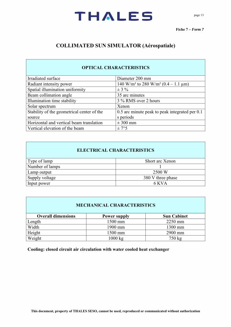
COLLIMATED SUN SIMULATOR (Aérospatiale)
OPTICAL CHARACTERISTICS
Irradiated surface Diameter 200 mm Radiant intensity power 140 W/m² to 280 W/m² (0.4 – 1.1 µm) Spatial illumination uniformity ± 3 % Beam collimation angle 35 arc minutes Illumination time stability 3 % RMS over 2 hours Solar spectrum Xenon Stability of the geometrical center of the source
0.5 arc minute peak to peak integrated per 0.1 s periods
Horizontal and vertical beam translation ± 300 mm Vertical elevation of the beam ± 7°5
ELECTRICAL CHARACTERISTICS
Type of lamp Short arc Xenon Number of lamps 1 Lamp output 2500 W Supply voltage 380 V three phase Input power 6 KVA
MECHANICAL CHARACTERISTICS
Overall dimensions Power supply Sun Cabinet
Length 1500 mm 2250 mm Width 1900 mm 1300 mm Height 1500 mm 2900 mm Weight 1000 kg 750 kg Cooling: closed circuit air circulation with water cooled heat exchanger

page 14
This document, property of THALES SESO, cannot be used, reproduced or communicated without authorization
Fiche 7 – Form 7
COLLIMATED SUN SIMULATOR
(Aérospatiale)

page 15
This document, property of THALES SESO, cannot be used, reproduced or communicated without authorization
Fiche 8 – Form 8
SOLAR SIMULATOR DOUBLE OUTPUT MODEL (Matra Marconi Space)
OPTICAL CHARACTERISTICS
Irradiated surface Coll. Beam Ø 90 mm Div. Beam Ø 800 mm Radiant intensity power 1082 W/cm² (0.8 cs) 1353 W/cm² (1 cs) Spatial illumination uniformity ± 3% ± 3% Illumination time stability
Temporal stability over 24 h ± 1%
± 1%
Beam collimation angle 32 arc minutes Beam divergence angle ± 6°25' Solar spectrum Xenon Xenon
ELECTRICAL CHARACTERISTICS
Type of lamp Short arc Xenon Number of lamps 1 Lamp output 6500 W Supply voltage 380 V three phase Input power 15 KVA
MECHANICAL CHARACTERISTICS
Overall dimensions Sun Cabinet
Length 2500 mm Width 1300 mm Height 2600 mm Weight 1500 kg Cooling: closed circuit air circulation with water cooled heat exchanger

page 16
This document, property of THALES SESO, cannot be used, reproduced or communicated without authorization
Fiche 8 – Form 8
SOLAR SIMULATOR DOUBLE OUTPUT MODEL (Matra Marconi Space)
page 17
This document, property of THALES SESO, cannot be used, reproduced or communicated without authorization
Fiche 9 – Form 9
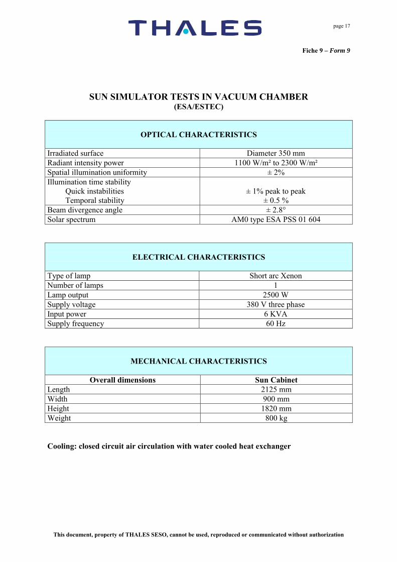
SUN SIMULATOR TESTS IN VACUUM CHAMBER (ESA/ESTEC)
OPTICAL CHARACTERISTICS Irradiated surface Diameter 350 mm Radiant intensity power 1100 W/m² to 2300 W/m² Spatial illumination uniformity ± 2% Illumination time stability
Quick instabilities Temporal stability
± 1% peak to peak
± 0.5 % Beam divergence angle ± 2.8° Solar spectrum AM0 type ESA PSS 01 604
ELECTRICAL CHARACTERISTICS
Type of lamp Short arc Xenon Number of lamps 1 Lamp output 2500 W Supply voltage 380 V three phase Input power 6 KVA Supply frequency 60 Hz
MECHANICAL CHARACTERISTICS
Overall dimensions Sun Cabinet
Length 2125 mm Width 900 mm Height 1820 mm Weight 800 kg Cooling: closed circuit air circulation with water cooled heat exchanger

page 18
This document, property of THALES SESO, cannot be used, reproduced or communicated without authorization
Fiche 9 – Form 9
SUN SIMULATOR TESTS IN VACUUM CHAMBER (ESA/ESTEC)
page 19
This document, property of THALES SESO, cannot be used, reproduced or communicated without authorization
Fiche 10 – Form 10
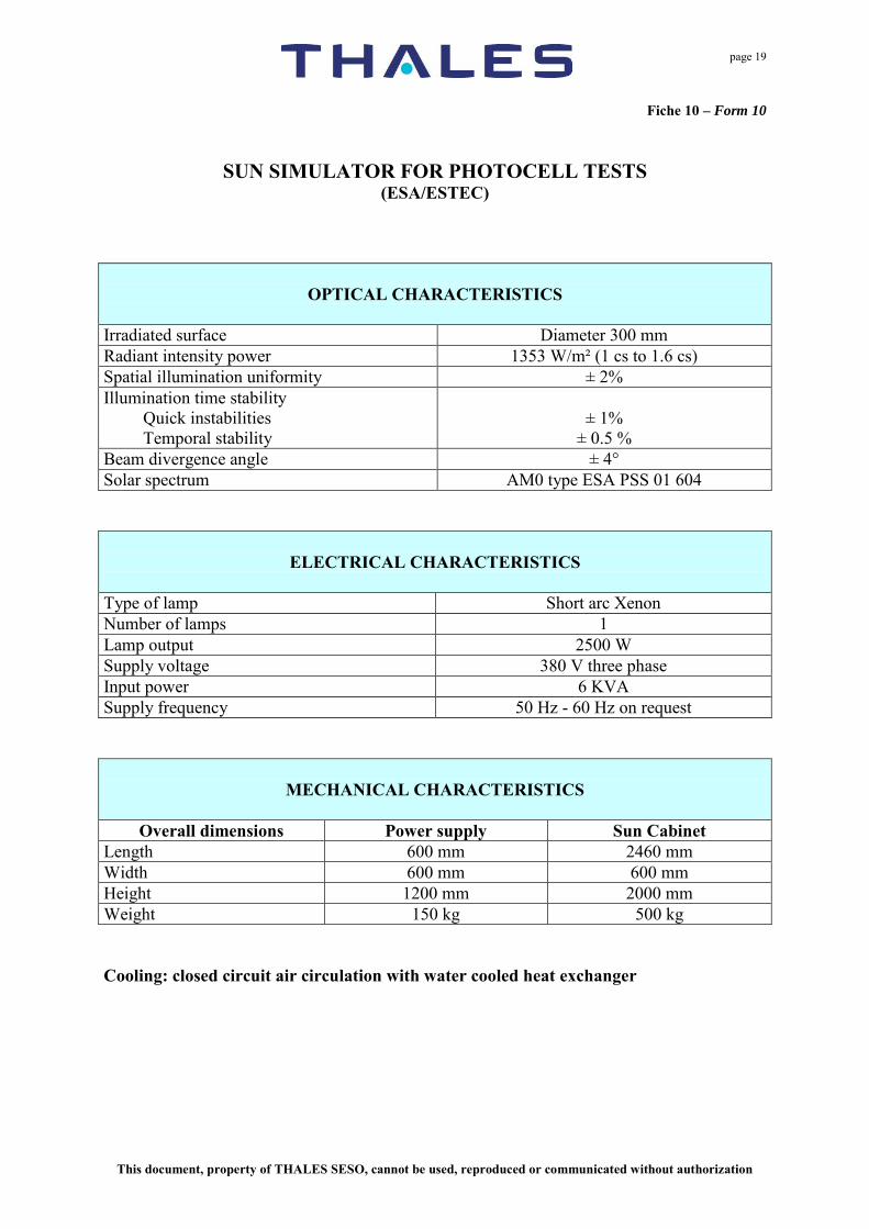
SUN SIMULATOR FOR PHOTOCELL TESTS (ESA/ESTEC)
OPTICAL CHARACTERISTICS
Irradiated surface Diameter 300 mm Radiant intensity power 1353 W/m² (1 cs to 1.6 cs) Spatial illumination uniformity ± 2% Illumination time stability
Quick instabilities Temporal stability
± 1%
± 0.5 % Beam divergence angle ± 4° Solar spectrum AM0 type ESA PSS 01 604
ELECTRICAL CHARACTERISTICS
Type of lamp Short arc Xenon Number of lamps 1 Lamp output 2500 W Supply voltage 380 V three phase Input power 6 KVA Supply frequency 50 Hz - 60 Hz on request
MECHANICAL CHARACTERISTICS
Overall dimensions Power supply Sun Cabinet
Length 600 mm 2460 mm Width 600 mm 600 mm Height 1200 mm 2000 mm Weight 150 kg 500 kg Cooling: closed circuit air circulation with water cooled heat exchanger

page 20
This document, property of THALES SESO, cannot be used, reproduced or communicated without authorization
Fiche 10 – Form 10
SUN SIMULATOR FOR PHOTOCELL TESTS (ESA/ESTEC)

page 21
This document, property of THALES SESO, cannot be used, reproduced or communicated without authorization
Fiche 11 – Form 11 SUN SIMULATOR TEMPERATURE CONTROLED TEST CHAMBER
(AEROSPATIALE)
OPTICAL CHARACTERISTICS
Irradiated surface 2.5 m x 0.5 m Radiant intensity power 1120 W/m² Spatial illumination uniformity ± 10% Solar spectrum GAM EG 13 type AM 1.5
ELECTRICAL CHARACTERISTICS
Type of lamp THALES SESO lamp Number of lamps 10 Lamp output 1200 W Supply voltage 380 V three phase Input power 19 KVA Supply frequency 50 Hz - 60 Hz on request
MECHANICAL CHARACTERISTICS
Overall dimensions Sun Cabinet
Length 3300 mm Width 1050 mm Height 800 mm Weight 300 kg Cooling: natural convection

page 22
This document, property of THALES SESO, cannot be used, reproduced or communicated without authorization
Fiche 11 – Form 11 SUN SIMULATOR TEMPERATURE CONTROLED TEST CHAMBER
(AEROSPATIALE)

page 23
This document, property of THALES SESO, cannot be used, reproduced or communicated without authorization
Fiche 11 – Form 11

page 24
This document, property of THALES SESO, cannot be used, reproduced or communicated without authorization
Fiche 12 – Form 12
UV SUN SIMULATOR
OPTICAL CHARACTERISTICS
Irradiated surface Diameter 170 mm Radiant intensity power 584 W/m² (0.2 – 0.4 µm) (5 cs UV) Spatial illumination uniformity ± 10% Illumination time stability
Temporal stability
± 5 % Solar spectrum UV Xenon (200-400 nm) Ripple flux > 400 nm (ratio between visible light and UV light)
10% to 20% between 200-400 nm
Beam collimation angle ~ 8° Beam divergence angle ~ 10°
ELECTRICAL CHARACTERISTICS
Type of lamp Short arc Xenon Number of lamps 1 Lamp output 6500 W Supply voltage 380 V three phase Input power 15 KVA
MECHANICAL CHARACTERISTICS
Overall dimensions Sun Cabinet
Length 2070 mm Width 950 mm Height 2500 mm Weight 1000 kg Cooling: closed circuit air circulation with water cooled heat exchanger

page 25
This document, property of THALES SESO, cannot be used, reproduced or communicated without authorization
Fiche 12 – Form 12
UV SUN SIMULATOR

page 26
This document, property of THALES SESO, cannot be used, reproduced or communicated without authorization
Fiche 13 – Form 13

page 27
This document, property of THALES SESO, cannot be used, reproduced or communicated without authorization
Fiche 13 – Form 13

page 28
This document, property of THALES SESO, cannot be used, reproduced or communicated without authorization
Fiche 13 – Form 13

page 29
This document, property of THALES SESO, cannot be used, reproduced or communicated without authorization
Fiche 14 – Form 14
SOLAR SIMULATOR for LABORATORY (PHOTOVOLTAIC CELLS RESEARCH CENTER)
OPTICAL CHARACTERISTICS
Irradiated surface Ø 300 mm Radiant intensity power 920 à 1 900 W/m2
Spatial illumination uniformity ± 2.5 % Illumination temporal stability ± 1 % Luminance curve According to solar luminance Beam collimation angle ± 2.5 % Solar spectrum AM0 or AM1
ELECTRICAL CHARACTERISTICS
Type of lamp Short Arc Xenon Number of lamps 1
Lamp output 2.5 KW Power supply voltage 380 V three phases Power supply frequency 50 Hz – 60 Hz on request
MECHANICAL CHARACTERISTICS
Overall dimensions
Length 1 100 mm Width 1 100 mm Height 2 300 mm Weight ~ 400 kg
Cooling: closed circuit air circulation.

page 30
This document, property of THALES SESO, cannot be used, reproduced or communicated without authorization
Fiche 14 – Form 14
page 31
This document, property of THALES SESO, cannot be used, reproduced or communicated without authorization
Fiche 15 – Form 15
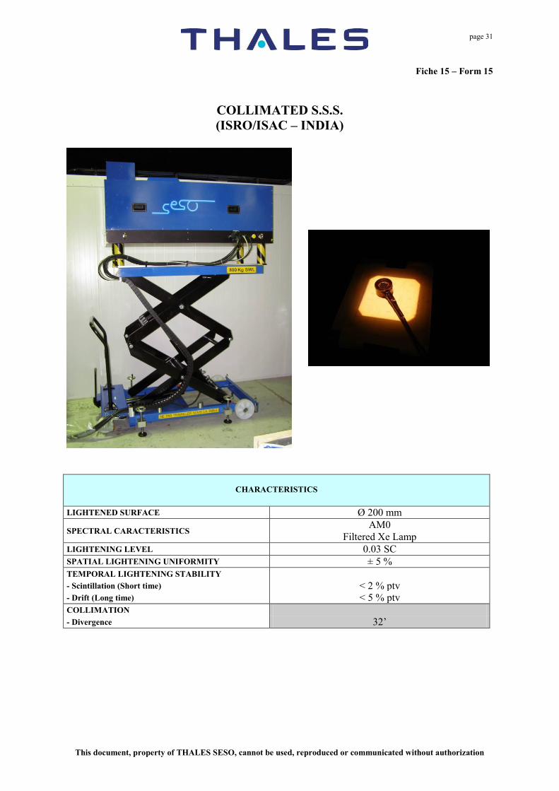
COLLIMATED S.S.S. (ISRO/ISAC – INDIA)
CHARACTERISTICS
LIGHTENED SURFACE Ø 200 mm
SPECTRAL CARACTERISTICS AM0
Filtered Xe Lamp LIGHTENING LEVEL 0.03 SC SPATIAL LIGHTENING UNIFORMITY ± 5 % TEMPORAL LIGHTENING STABILITY - Scintillation (Short time) < 2 % ptv - Drift (Long time) < 5 % ptv COLLIMATION - Divergence 32’

page 32
This document, property of THALES SESO, cannot be used, reproduced or communicated without authorization
Fiche 16 – Form 16
Multi Sources Solar Simulator (NMSSS) (ESA/INTA Spain)
Main issues :
- Test of solar cells with three junctions corresponding to large spectrum (350 – 1900
nm) sensitivity. - Independent test for the three spectral bands: Necessity of three sources (one Xenon, 2
halogens). Can be expanded to 5 sources. - Spectral separation thanks to dichroïc mirrors (large size mirrors : up to 450 mm) - Level adjustable on each line without changing the spectral distribution in the range
0.8 to 1.2 SC. - High homogeneity level in the target plane (diameter >140 mm) - Computer control for ease of use, operating traceability and securities management

page 33
This document, property of THALES SESO, cannot be used, reproduced or communicated without authorization
Specified performances, features:
Beam size: ≥ 140 mm diameter (with respect of all specifications)
(About 200 mm square for Xe, 165 mm square for Ha2 and 155 mm square for Ha1).
Beam non-uniformity: ≤ 2% (UFP1) and ≤0.9% (UFP2) over 140 mm diameter for all lights combined in the range 0.8 to 1.2 SC. (UFP1: corresponds to pick to valley value and UFP2 to RMS value)
Light Beam divergence: < 2.5°.
Solar intensity: Level specified adjustable between 0.8 and 1.2 SC (Solar Constant). Actually adjustable down to 0 SC.
Level adjustment: Adjustable with an accuracy better than 0.1% on whichever solar cell short circuit current parameter.
Spectrum: Matching spectrum AM0, ESA PSS 01604 with 135.3 mW/cm 2
+/- 15 % for the spectral band 350-1900 nm (average over 100 nm to 250 nm wide spectral windows)
Beam Intensity stability:
Xe Short term : ≤ 1% peak to peak variation over 1 minute
Xe long term : ≤ 1% peak to peak variation over 10 hours
Ha Short term : ≤ 0.5% peak to peak variation over 1 minute
Ha long term : ≤ 0.5% peak to peak variation over 10 hours

page 34
This document, property of THALES SESO, cannot be used, reproduced or communicated without authorization
Connection characteristics
- Water
Input Ø25 mm flexible tube – 1000 l/h – Temperature ≈ 18°C output Ø25 mm flexible tube no limitation Pressure > 3 bars Delta pressure (Input/Output) < 0.3 meter of water
- Air
Input Ø12 mm flexible tube Rate negligible Pressure > 5 bars.
- Electrical power:
380 V – 3 phases + neutral + ground, 50 Hz Power 15 kW Supply stability +/- 10%
Ambient conditions
The collimated sun simulator and all its control command equipment will endure the following ambient conditions:
- Operating temperature: + 10°C / + 30°C.
- Storage temperature: 0°C to 50°C.
- Hygrometry (operating or storage): 45 % to 65 % RH (no condensing).

page 35
This document, property of THALES SESO, cannot be used, reproduced or communicated without authorization
NMSSS - Software features:
+ Calibration tables and securities management (cooling system, lamps defaults, temperature, level setting …).
MMMAAANNNUUUAAALLL MMMOOODDDEEE
Individual lighting, shuttering and level setting for each line (in %).
AAAUUUTTTOOOMMMAAATTTIIICCC MMMOOODDDEEE
Global lighting, shuttering and level setting simultaneously for the 3 lines (in SC).
MMMAAAIIINNNTTTEEENNNAAANNNCCCEEE MMMOOODDDEEE
Addressing each individual actuator and detector with appropriate password.
MMMOOONNNIIITTTOOORRRIIINNNGGG
Survey of main parameters (voltage and current of each lamp, operating temperature, position of the shutters…). Monitoring files storage, log file...

page 36
This document, property of THALES SESO, cannot be used, reproduced or communicated without authorization
APPENDIX
SCIENTIFIC ARTICLES

page 37
This document, property of THALES SESO, cannot be used, reproduced or communicated without authorization
SOLAR SIMULATORS Proceedings – ETTC Conference
MARSEILLE – France – June 11-14 , 2001 Solar simulators. Solar simulators are very much in demand in spatial activities. With vacuum and weightlessness, sun remains one of the key elements of the spatial environment. In spite of its noxious effects on materials lifetime, sun is highly appreciated for its energetic source brought to the satellites through photovoltaic cells. Considering the high cost of space programs, and the breakdown risks, that have to be reduced to the maximum, it is imperative to proceed to tests on the ground of complete satellites or sub-systems, in environmental conditions as close as possible to the space conditions. 1/ General technical characteristics. We must create in laboratory or in experimental chamber a lightening as close as possible to the sunlight one: In laboratory, it is possible to do it with independent equipment, with easy interface and environmental specifications. In experiment chambers, those specifications take into account the other simulation means and their restrictions: climatic conditions (temperature), vacuum, electromagnetic protection, reduced volume… A solar simulator is defined by the following characteristics: a) Lightened surface (or volume).
Depending on the tested type of material, the lightened surface (or volume) diameter, generally circular (or cylindrical or spherical), will vary from several centimeters to several meters.
b) Spectral Profile. In space, the sun spectral profile, referenced AIR MASS ZERO (AM0), is close to the black body spectral profile at T = 5 900°K. On earth, it is modified by the filtration effect of the atmosphere and by the reflection effect of the earth. Depending on the altitude, latitude, and cloudy conditions, two spectrums are generally defined, AM1 and AM1.5, specifically defined. Short arc Xenon lamps (T = 5 800°K), the closest to the sun spectrum, are generally used in solar simulation. If necessary, suitable filters allow to reach the AM0, AM1 and AM1.5 specifications. Here-after you will find a new solution proposed by THALES THALES SESO to better approach the AM0 profile (Ray spectrum suppressed).
c) Lightening level. In space, the lightening level of the sun (still designed by solar constant “SC”) reaches 1 353 W/m2, integrated on the whole electromagnetic waves spectrum (spectral profile AM0).
If integration is limited to the most significant range 250 – 2400 nm, the lightening level is of 1293 W/m2, which is 95 % of here-above value. On earth, - it is of 1040 W/m2, for the AM1 spectrum
integrated between 200 & 2825 nm - it is of 1120 W/m2, for the AM1.5 spectrum
integrated between 300 & 3000 nm Most of the solar simulators recreate the lightening level of 1 SC with a possible fluctuation between 0.6 and 1.2 SC. Nevertheless, values of 0.01 to 0.02 SC are in some cases sufficient (for collimated simulators for example), and in other cases, a lightening of several SC in a specific spectral strip is necessary (UV simulators of 5 SC for fastened ageing process)
d) (Surface / volume) lightening uniformity. It is generally measured on a plane perpendicular to the lightening beam. A perfect solar lightening uniformity is very difficult to recreate in a solar simulator. Depending on the requested requirement level, variations of several percents can appear. This uniformity can sometimes be specified in a volume on both sides of the reference plane. In this specific case, we can reach uniformities of a few percents, but a perfectly collimated simulator is necessary.
e) Temporal lightening stability. The stability level of the sun in space is very difficult to re-create in a solar simulator. Nevertheless, we are quite able to reach it. Two stability (or instability) types can be distinguished: In a very short time scale (second), for frequencies between 10 and 100 Hz, we can observe lightening fluctuations or scintillations of several percents. In a longer time scale (several hours), a drift of several percents is visible. This instability is due to the lamp itself, but also to the electrical alimentation of the lamp. THALES THALES SESO uses highly stabilized alimentation systems in order to reduce it to 1 to 2%. Moreover, the temporal drift can be minimized (even suppressed) by indexing the lamp current intensity to the requested lightening level.
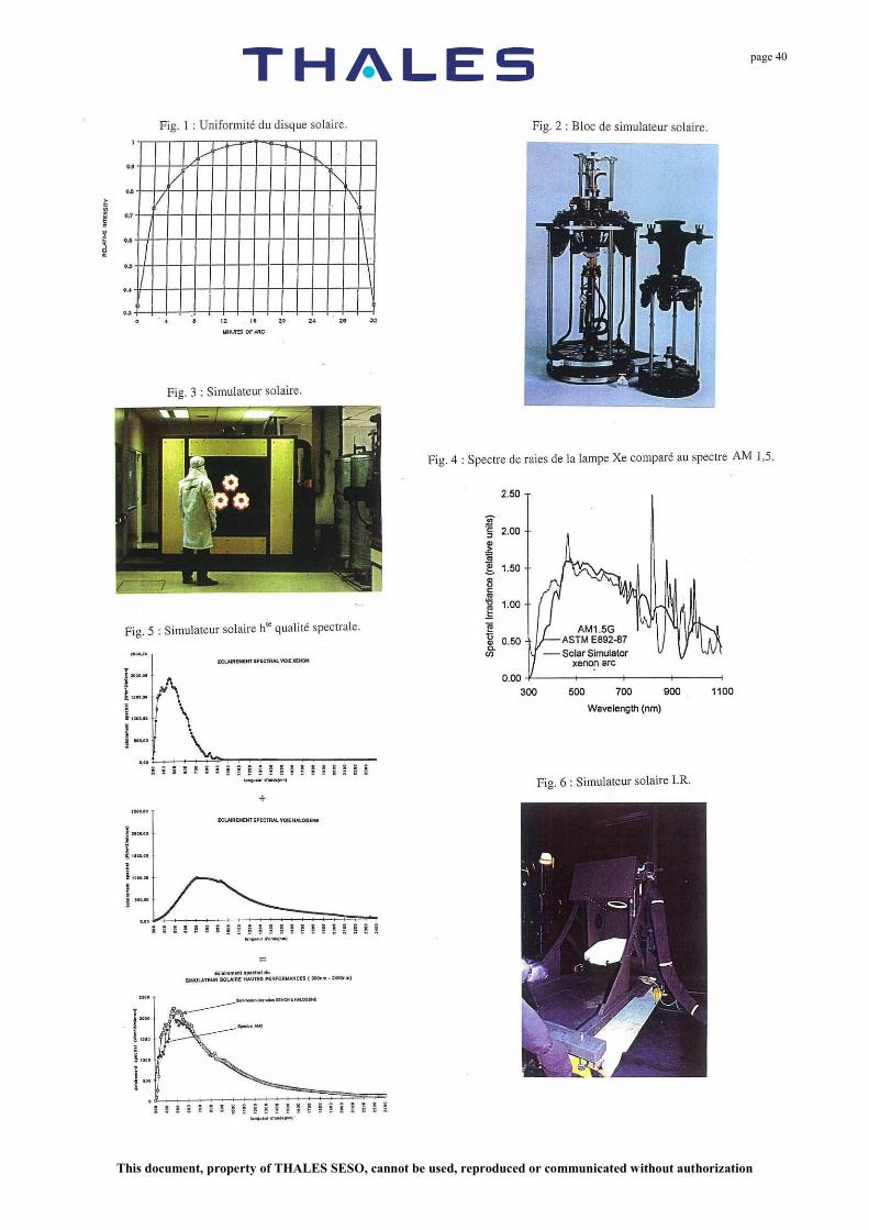
f) Solar disk uniformity / divergence. The sun divergence corresponds to its visible angle (32’). The solar disk uniformity is represented on Fig.1. Excluding for “collimated” solar simulators, where those two aspects (respect of the 32’ and uniformity of the solar disk) are important, a divergence of ± 1° to ± 5° is generally accepted for the other solar simulators.

page 38
This document, property of THALES SESO, cannot be used, reproduced or communicated without authorization
2/ Examples of THALES THALES SESO solar simulators. We present here-after some examples of specific THALES THALES SESO Solar Simulators (SSS). To answer to the requirements of the different final application (See table 1) types, some particular efforts have been made on specific parameters: a) Large lightened surface SSS :
Solar panels for the thermal control of satellites or sub-systems
b) High spectral quality SSS : Photovoltaic cells tests
c) (UV) SSS : Ageing tests
d) Large surface (IR) SSS : Aircrafts IR signatures
e) Highly collimated SSS : Spatial platforms or instruments behavior tests
A/ Large lightened surface solar simulators. The principle consists in adding the light beams produced by several source blocks. Each block (Fig. 2) is composed of lenses and mirrors collecting through different optical channels the light produced by a short arc Xenon lamp. By superposition, in the reference plane, of the different optical channels, the non uniformity of the Xenon lamp lightening is balanced and a final uniformity of several percents per block can be obtained. The addition of each block’s light beams can be achieved by: - Direct superposition in the reference plane, if the
number of blocks is reduced: this way, the divergences add up.
- Indirect superposition in a pupil plane re-imaged by a set of lenses and mirrors: this way, the total divergence can be slightly reduced.
THALES THALES SESO has thus manufactured a simulator (diameter 1.6 m) for the CIEMAT of MADRID associating 3 blocks (direct superposition) equipped with 7 KW Xenon lamps, intended to test solar panels (See Fig. 3). The INTESPACE simulator of TOULOUSE ensures a 3.8 m diameter lightening by the association of 36 blocks (indirect superposition) equipped with Xenon lamps of 6.5 KW in order to test the thermal behavior of complete satellites. B/ High spectral reliable solar simulator. Xenon lamps present a ray spectrum structure between 0.75 and 1.5 microns (Fig. 4), especially detrimental in the spectrum band 0.75 – 0.95 microns, with regard to the requirements of the solar cells new generations. The concept of a highly reliable spectral simulator suppressing this ray spectrum consists in adding the complementary lightening of two different lights (Fig. 5) - The first one (ensuring the UV + VIS part) remains a
Xenon lamp deprived of its IR (and ray spectrum) part by a low pass filter.
- The second one (ensuring the IR part) consists in a halogen lamp deprived of its VIS part by a high pass filter.
First, we’ve realized an experimental instrumentation (for INTA Madrid) allowing to validate this new concept. The
spatial mixing is made of two convergent optic sets focused on the same reference plane. You can see on Fig. 5 that a spectrum much closer to the AM0 reference is reached. C/ UV (only) solar simulation. Realized for ONERA-CERT based in Toulouse, it is intended to fast ageing tests. The only UV part (200 – 400 nm) is taken into account. The light beam source is an optic block as represented on Fig. 2, equipped with a 6.5 KW Xenon lamp. To increase the power density ~ 5CS (UV), a recapture optic concentrates the beam on a diameter reduced to 170 mm. Moreover, the obligation to suppress the VIS spectrum (ratio between VIS flux and UV flux < 8%) requires a filtration by means of mirrors (dichroïc filters or large band interferential filters). D/ IR (only) solar simulator. Realized for the DGA/DCE/CEAT, it is intended to the IR signature characterization of aircrafts under control (Fig. 6). Only the IR parts (3 – 5 μm and 8 – 12 μm) are considered. The selected beam source is a black body whose temperature = 800° K. The need to cover a large dimension area Ø 2400 mm with a divergence reduced to ± 2% induced the choice of a large black body associated with a large Germanium projection optic Ø 320 mm. Some other constraints made this realization particularly sensitive: - The need to move the beam around an experimental
central area inside a thermal chamber (-50°C) with a reproducible positioning (less than 0,1° difference) induced the manufacturing of an imposing and extremely precise mechanical support (See Fig. 6)
- The need for the beam source outside the IR beam directed on the target, not to interfere with the thermal chamber equilibrium.
- And last, the need of a remote controller outside the thermal chamber and the need to get stable and recurrent lightening values required the installation of temperature regulation systems and automatic piloting system, associated to many automatic security devices.
E/ Collimated solar simulators. Generally intended to behavior tests, they need the most reliable reproduction of the sun space energetic characteristics: - 32’ divergence - solar disk uniformity (Fig. 1) For this, we use the light beam of a short arc Xenon lamp following a single direction, and collected in a reduced solid angle, associated with an optical projection system of KOEHLER type the 32’ divergence will be controlled by the installation of a diaphragm in the focus of the lens. - The solar disk uniformity will be improved by the
installation of a homogeneity optical device located near the diaphragm.
The AM0 spectrum generally required for this type of simulator is obtained by spectral filtration of the infrared 0.8 – 1 μm bandwidth. In addition to the collimated simulator Ø 200 mm manufactured for ALCATEL SPACE simulating, by a set of mirrors, different illuminating angles, THALES
page 39
This document, property of THALES SESO, cannot be used, reproduced or communicated without authorization
THALES SESO just realized for ISRO (INDIA) a collimated simulator Ø 200 mm with a high uniformity solar disk (Fig. 1). CONCLUSION Continuous advances in the field of lights sources constantly modify the optical solutions for light projection in simulators. This progress contributes to the research of increasing performances in every final solution, and thus helps THALES THALES SESO to develop state-of-the-art projection devices.
page 40
This document, property of THALES SESO, cannot be used, reproduced or communicated without authorization

page 41
This document, property of THALES SESO, cannot be used, reproduced or communicated without authorization
page 42
This document, property of THALES SESO, cannot be used, reproduced or communicated without authorization

page 43
This document, property of THALES SESO, cannot be used, reproduced or communicated without authorization

page 44
This document, property of THALES SESO, cannot be used, reproduced or communicated without authorization

page 45
This document, property of THALES SESO, cannot be used, reproduced or communicated without authorization

page 46
This document, property of THALES SESO, cannot be used, reproduced or communicated without authorization

page 47
This document, property of THALES SESO, cannot be used, reproduced or communicated without authorization

page 48
This document, property of THALES SESO, cannot be used, reproduced or communicated without authorization

page 49
This document, property of THALES SESO, cannot be used, reproduced or communicated without authorization

page 50
This document, property of THALES SESO, cannot be used, reproduced or communicated without authorization

page 51
This document, property of THALES SESO, cannot be used, reproduced or communicated without authorization

page 52
This document, property of THALES SESO, cannot be used, reproduced or communicated without authorization

page 53
This document, property of THALES SESO, cannot be used, reproduced or communicated without authorization

page 54
This document, property of THALES SESO, cannot be used, reproduced or communicated without authorization

page 55
This document, property of THALES SESO, cannot be used, reproduced or communicated without authorization

page 56
This document, property of THALES SESO, cannot be used, reproduced or communicated without authorization

page 57
This document, property of THALES SESO, cannot be used, reproduced or communicated without authorization
THALES SESO PÔLE D’ACTIVITÉS D’AIX-LES-MILLES - 305, rue Louis Armand - CS 30504
13593 - AIX-en-PROVENCE Cedex 3 - FRANCE Internet : http://www.seso.com e-mail : [email protected]
: [33] (0)4 42 16 85 00 - : [33] (0)4 42 16 85 85