a megawatt power millimeter- wave phased-array radar · a megawatt power millimeter- wave...
TRANSCRIPT

A Megawatt Power Millimeter- Wave
Phased-Array Radar
A.A. Tolkachev, B.A. Levitan, G.K. Solovjev, V.V. Veytsel and V.E. Farber JSC “Radiophyzika ”
ABSTRACT
This article describes the design and development of a multi-megawatt radar “Ruza,” having a large mechanically steered, millimeter-wave, ,
phased-array antenna.
INTRODUCTION
For certain radar applications there are clear advantages in moving upward in frequency. Radar systems are limited in gain and angular accuracy by the size of the available antenna in wavelengths, whilst their effective bandwidth is a fixed percentage of the operating frequency, limited by the frequency dependence of the antenna and associated RF components. A move into the millimeter wave region enables the radar designer to produce a high energy density and angular resolution in space with realistic transmitter power and antenna aperture; to use a wide instantaneous bandwidth; and to obtain increased Doppler frequency shifts for a given spread of radial velocities [l]. One of the most interesting applications of millimeter-wave radar is the detection and tracking of objects in orbit around the Earth, which has
Author’s Current Address: A.A. Tolkachev, B.A. Levitan, G.K. Solovjev, V.V. Veytsel and V.E. Farber, JSC “Radiophyzika,” 10, Geroev Panfilovsev St., P.O. Box 1, Moscow 123363, Russia.
Manuscript received September 1999; revised November 9,1999.
0885/8985/00/ $10.00 0 2000 IEEE
Fig. 1. The MMV radar “Ruza,” situated on Sary-Shagan range (Kazakhstan)
become possible due to the development of very high power millimeter-wave sources. The USA operates such a
IEEE AES Systems Magazine, Jury 2000 LJ
radar at the Kwajalein Atoll test range [2]. This has a large mechanically steered reflector antenna with a very narrow beamwidth which limits its ability to observe multiple moving targets.
Ka-band radar based on a mechanically steered phased array that provides limited electronic sector scan over a broad mechanical scan sector are described. Operating in conjunction with a centimeter radar, the resulting system demonstrates considerable flexibility for the observation of Earth-orbit targets. The detection sensitivity is achieved by using a new type of high power amplifier - the gyroklystron - in conjunction with modern solid-state low noise amplifiers in the receive path. The radar, known as “Ruza,” was built in the USSR in 1989, and tested at the Sary-Shagan test range in Kazakhstan (see Figure 1, on previous page). Tracking of a large number of satellites and other ballistic objects were carried out, and during the period 1990 to 1993, a number of improvements to the hardware were made which significantly improved the sensitivity and accuracy of the radar [3].
In this paper, the principles and realization of a
DESIGN CONSIDERATIONS
The main tasks in the development of the “Ruza” radar were: understanding system issues in observation (detecting, tracking) of space objects with millimeter radar; the hardware system design for generation, amplification, transmission, reception, and beamforming of the signal at millimeter wave frequencies; development of algorithms and programs for data processing, and testing and maintenance of the millimeter-wave radar; defining how the operation of and data from the radar would be integrated into a national space surveillance system.
During the development of the radar a number of new components and system design concepts were created: a mechanically steered phased array antenna; solid-state low-noise parametric amplifiers in the receive path of the phased-array elements; a complete run of overmoded high power circular waveguide with complex geometry; a coherent multi-stage high power transmitter; gyroklystron high power amplifiers with cryomagnets; multiple cryostats with closed liquid helium systems.
The performance of the radar following the improvement programme mentioned earlier is shown in Table 1.
Table 1: Main technical performance of the radar “Ruza”
,.._ ..................................
/ TRANSMITTER . ................................ l_l
.............................
I ...................... PROCESSING
SYSTEM
............................
ANTENNASERVO DRIVE
i I ............................................
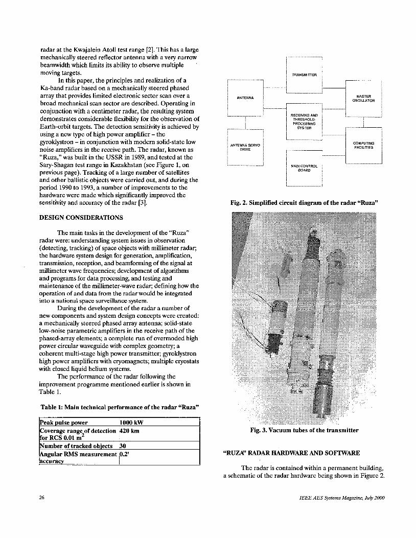
Fig. 2. Simplified circuit diagram of the radar “Ruza”
Fig. 3. Vacuum tubes of the transmitter
“RUZK’ RADAR HARDWARE AND SOFTWARE
The radar is contained within a permanent building, a schematic of the radar hardware being shown in Figure 2.
26 IEEE AES Systems Magazine, July 2000

02 TO H Q ~ MODE C /
Half-power beamwidth 4.2’
for transmit 5.0’
for reception Electronic-steering sector 50’ Gain of antenna for transmiq60 dBi
INPUT
Fig. 4. Structure of “Stremja3M” gyroklystron
Transmitter
two identical amplifying chains matched in phase, the power combining taking place in free space. When the radar is operating, the two chains are monitored and maintained in synchronism using analogue circuitry. Each chain consists of four stages of amplification. The first two stages use traveling wave tubes, the second two stages use gyroklystrons (see Figure 3 on previous page). The gyroklystrons require an intense magnetic field of magnitude 1.4 Tesla, which is generated by low temperature superconducting solenoids immersed in cryostats of liquid helium which maintain a temperature of 4.2” K. The parameters of the transmitters are shown in Table 2.
The transmitter power for the radar is provided by
Table 2: Main technical performance of the transmitter
electrodynamics system of the device consists of an input and output cavity, microwave signal input and output devices using a mirror Hoi to H02 mode changer at the device input and a corrugated H02 to Hoi mode changer at the output, with high voltage isolation at the device input. Open, cylindrical cavities with smoothly changing section are used. The cavities are separated by an electron drift tube. A diffraction connection of cavities with the input/output of the gyroklystron is implemented by means of diaphragms.
Antenna
used for both transmission and reception. The radiating face is 7.2 m in diameter (Figure 5 on next page), and consists of 120 removable antenna elements (antenna modules), each module being separately controlled for gain and phase. A simplified circuit diagram of the antenna is shown in Figure 6, on next page. The parameters of the antenna are shown in Table 3.
The “Ruza” is a monostatic radar with a single face
Table 3: Main technical performance of the antenna
The research work into gyrotrons undertaken for the “Ruza” radar has resulted in the development of very high power gyrotron amplifiers: the gyroklystrons “Stremya-1” and “Stremya-2.” The structure of the “Stremya-2” gyroklystron is shown in Figure 4. A magnetron-type adiabatic electron gun produces a helical flow of electrons, which are constrained by the intense magnetic field produced by a superconducting solenoid. To produce the optimum electron trajectory, the magnetic field is adjusted using a correction winding [4]. The
Each module comprises a reflector, a ferrite phase shifter, a low noise amplifier with input protection, and
IEEE AES Systems Magazine, July 2000 27

Fig. 5. Mechanically-steering phased-array antenna
control and testing circuitry. The reflector has a Cassegrain feed, the main reflector being a truncated paraboloid, with a shaped sub-reflector to efficiently illuminate the main reflector. Circular polarization is used in transmit, with an ellipticity of 0.9. The phasing of the antenna modules on both transmit and receive is via three-bit ferrite phase shifters. The module low noise amplifier is a custom designed parametric amplifier with an integral solid-state pump generator. To protect the amplifiers from direct transmitter breakthrough, two stages of protection are provided: a gas-discharge duplexer (TR switch), followed by a controlled diode attenuator. Care was taken in the system and hardware design to ensure that phase drift in the amplifiers could be measured and compensated for.
In receive mode, the module signals are processed by a waveguide beamforming matrix (Figure 7) to form a monopulse cluster of beams for angle and range measurements. In transmit mode, the antenna face is fed from two off-mount transmitters via a waveguide system. The path length of the waveguide system is some 40 m, and
I
Fig. 7. Waveguide beam-forming matrix
the requirement for a minimal insertion loss necessitated the development of a multi-mode waveguide together with compatible components. A circular waveguide of 80 mm
28 IEEE AES Systems Magazine, July 2000

Fig. 8. Waveguide power splitter
diameter was used operating in Hoi mode. To distribute the power to the 120 modules, a system of power splitters was designed using 1:2 and 1:31 splits. A radial power splitter in the circular waveguide provided the 1:31 split (one of the outputs being for diagnostics and calibration), the element outputs being in rectangular waveguide of 16 x 8 mm section operating in TEoi mode (Figure 8).
To set up the phased array, a test antenna installed on a special test tower was used, and then operated either as a receiver or a transmitter to set up the module phase-shifts.
The millimeter phased-array is mounted on an elevation over azimuth mount which is in turn mounted on a concrete base. This provides the phased-array face with a mechanical scan in azimuth of f 135" and in elevation from 2" to 178". The mechanical rigidity of the phased-array construction ensures that the array face remains electrically flat in both static and dynamic conditions. The radar is enclosed in a space-frame radome 20.5 m in diameter. The radome material is made up of two layers of specially designed composite material 0.2 mm thick. Signal loss through the radome is less than 0.8 dB. An air conditioning system stabilizes the temperature and humidity within the radome.
Processing System
receiving and processing system has two components, one on-mount, and the other off-mount. Further RF processing is provided on-mount, whilst matched filtering, digitization, and digital processing is done off-mount. The receiving and processing chain can process three types of transmitted intra-pulse waveform: linear frequency sweep with 4.6 MHz swept bandwidth; linear frequency sweep with 100 MHz swept bandwidth and fixed frequency. The beamformer produces five outputs which are amplified, down-converted, match-filtered, and digitized. The digital signals are then further processed. The dynamic range of each channel is 60 dB, although it is possible to increase
Following the monopulse beamforming network, the
this by a further 10 to 20 dB when receiving signals of high power by the use of switched attenuators in the signal path.
Matched filtering for the 4.6 MHz linear frequency sweep is carried out using a surface acoustic wave device, producing a compressed pulse of 0 . 3 ~ s duration. The receiver channel gains can be controlled to meet the particular processing requirements, for example, maintaining the output noise levels of the channels equal. The receiving channels are all linear prior to being digitized at a 4 MHz rate by a 7 bit logarithmic analogue-to-digital converter. Processing when the 100 MHz linear frequency sweep is used uses the principle of partial frequency demodulation. Here the local oscillator to the first mixer uses a linear frequency sweep similar to that transmitted, but with a frequency sweep by 4.6 MHz less than the received sweep, allowing the above processing to be used. This is similar to the technique described in [2].
Software
targets are carried out by programmable processors specially designed for the radar. The following functions are provided by the real-time software [5] :
The detection, plot extraction, and tracking of
Task scheduling: defining the sequence of pulses and corresponding reception intervals; control of input information flow to avoid losses; scheduling of the processing systems; defining areas of target detection; evaluation and prediction of antenna movement. Plot extraction: processing to suppress range sidelobes of the compressed signal; threshold detection; range and angle measurements on a single detection (plot formation); plot-to-track association. Tracking: creation of tracks of detected objects (track initiation); Kalman filtering of the tracks (track maintenance) -the Kalman filter is used both for track filtering of space objects and aircraft, etc. [3]; radar object coordinates samples distribution between the tracks; grouping of the targets for combined processing. Radar control: forming of detection areas; identification of tracked targets; control of the functional resources of the radar. Man-machine interface.
MAINTENANCE AND DIAGNOSTICS
The need to ensure that the coherence of the millimeter wave signal is maintained in time and space requires the use of a system testing and maintenance regime that is more complex than for radars in traditional surveillance bands. The system diagnostics are carried out by a set of dedicated hardware under software control. The following tasks are undertaken: providing confirmation of
IEEE AES Systems Magazine, July 2000 29

ti=
--”- ,~ .----
Fig. 9. Structure chart of automatic testing system for the radar “Ruza” -,
the availability of the sub-systems by continuous testing; localizing hardware faults down to line-replaceable items; testing the performance of the radar as a complete system using software and hardware simulators. The following test regimes are provided: continuous automatic testing; performance testing of devices or sub-systems (PT); system testing of radar using a test tower; periodic local off-line service testing. The structure of the testing system is shown in Figure 9, with further details of the test regimes given in the sections below.
Continuous Automatic Testing
undertaken to check that the sub-systems are within their specification, and to locate faults. It is implemented for all modes of operation.
Continuous automatic testing of the hardware is
Performance Testing (PT)
automatically search for faults in individual devices or sub-systems of the radar. It provides a quantitative measure of the devicehub-system parameters which are compared with their specification, and involves a sequence of separate tests that are organized in a manner which minimizes the average time taken by the fault search. Built-in testing and stimulating hardware of the sub-systems and devices is used for PT.
Performance testing is a central task undertaken to
......... .........,..... - ......................................
I
~
...................... , !_l - _ i. -.
.................. % ............ .................. , r..d ........
. . . . . . . . . . . . . . . ,
: . . . . . . . . . . .
RPP#IRliFUS i : ! . : . . . . I i : : ............ .- .................. -- ...................
...... .......................... - __..I .............. _ ..”. _.
. ................ ....... : ,._ .............. :...
Fig. 10. Simplified circuit diagram of antenna performance testing
Performance testing is carried out for the following main sub-systems: antenna system; receiving and processing systems; power servo drives. As an example, the organization of antenna system PT is described. A simplified diagram of the performance testing of the antenna sub-system is shown in Figure 10.
and receive modes. In receive mode, the master oscillator output, which is at the carrier frequency, is routed through the waveguide run to the test tower, and passed through the radar hardware to the data processing system. In
Automatic testing is carried out for both transmit
30 IEEE AES Systems Magazine, July 2000

transmit mode, the master oscillator output is passed along the main transmitter paths and radiated from the antenna face to the test tower, where the signal is collected and passed along the waveguide run to a receiving system and hence to the data processing system. Prior to these antenna tests being performed, the turning mount is arranged so that the mechanical broadside of the array face passes through the test tower antenna. During the performance testing the antenna is not moved mechanically. Since the test tower is in the near-field of the phased-array antenna aperture, the array is focused on the test tower by introducing a parabolic phase profile across the aperture by means of the phase shifters.
Antenna measurements are made in two ways. In the first, an evaluation of the antenna performance is made by measuring the shape and gain of the main lobe around its broadside position. Since the antenna is physically stationary, the pattern is measured by electronically scanning the beam by means of the phase-shifters. We shall call this electronic scan pattern the “angular response” pattern (ARP) [6] . From the ARP we can determine: amplitude and pointing direction of the beam peak; half-power beamwidth in the principle planes. The second approach to performance measurement of the array involves measuring the amplitude and phase aperture distribution (MAD), and is carried out by disabling all modules except the one under test by means of switches in the antenna modules. From the sequentially measured amplitudes and phases of the modules across the aperture, the following antenna parameters can be obtained: amplitude and phase aperture distribution; distribution statistics of the aperture distribution; location of faulty modules needing replacement.
necessary to carry out weekly phase/amplitude adjustment of the 120 antenna modules in both transmit and receive. When carried out manually, this takes several hours. When undertaken with the automatic system, which corrects the phase by updating the phase information stored in each module, the whole array can be re-calibrated in less than 20 minutes. The measured results of the APAD performance measurement are used to produce correcting factors which are incorporated in the computer control of the array beam steering. There has been found to be good correlation between manual and automatic phase correction.
During operation of the radar, it has been found
System Testing of Radar Using a Test Tower
checks are made on certain performance characteristics of the radar, such as: fast-changing errors in measurement of angle and range; slow-changing errors in measurement of angle coordinates. Histograms of angle and range coordinates measurements errors, and calculation of probability densities. The organization of the radar
As well as testing of the individual sub-systems,
performance testing (PT) is similar to the organization of antenna sub-system PT described above.
Local Periodic Service Testing As well as the above automatic testing, local
servicing is undertaken periodically. Here operators will use standard measuring equipment to check device and sub-system performance, as a check on the built-in testing.
CONCLUSION
The “Ruza” radar was built in 1987 - 1989 at the Sary-Shagan test range in Kazakhstan. It is believed to be the first monopulse, megawatt, multichannel radar operating in the millimeter wave band with a fully steered phased array antenna intended for target detection and tracking of objects in Earth orbit. During the programme a number of novel technical and system engineering solutions were developed. The radar can provide electronic surveillance over a sector of approximately 1 square degree with close to optical accuracy in single coordinate measurement. It is capable of tracking up to 30 targets in the whole upper hemisphere up to a distance of 4000 km. The large power-aperture product of the radar enable it to detect targets with a radar cross section of 0.01 m2 at ranges up to 420 km.
ACKNOWLEDGMENT
The authors are grateful to M.I. Petelin for his collaboration and support of this publication, as well as to Dr. W. Gregers-Hansen and Marconi Research Centre for their interest and assistance in editing the manuscript.
REFERENCES
[l] A.A. Tolkachev, V.A. Makota, M.P. Pavlova, A.M. Nikolayev, V.V. Denisenko and G.K. Solovjev, September 22-24,1998,
Large PAA for Millimeter Wave Band Radar, Proceedings of the XXllI Moscow International Conference Antenna Theory and Technology, Moscow.
[2] M.D. Abouzahra and R.K. Avent, 2 April 1994, The 100 kW Millimeter-Wave Radar at the Kwajalein Atoll,
IEEE Antennas and Propagation Magazine, 36.
[3] A.A. Tolkachev and V.E. Farber, November 14-17,1994, Atmosphere track parameters of ballistic target components estimating by Earth radar,
Proceedings of the 11 Intemational Conference Modem Issues of Protection from Ballistic Missiles, Moscow.
[4] A.V. Gaponov-Grekhov and V.L. Granatstein, 1994, Applications of High Power Microwaves,
Boston, London: Artech House.
[5] M.M. Zolotarev, A.A. Tolkachev and V.E. Farber, 1995, Some Episodes of Software Development for Modem Multi-channel Radar Facilities Incorporating PAA,
[6] D.B. Zimin, I.V. Kaplun and M.Yu. Kholshchevnikov, 1985,
Radiopromyshlennost, Moscow, 1/2, pp. 139-144.
Dynamic Technique of Patterns Measurement for Plane Digital-Commutative PAA,
Imestiya Vuzov, Radioelektronika series, 28,3, pp. 57-59.
IEEE AES Systems Magazine, Jury 2000 31