a paris-model approach to modular simulation
TRANSCRIPT

Environmental Modelling & Software 14 (1999) 511–517www.elsevier.com/locate/envsoft
A paris-model approach to modular simulation
Thomas Maxwell*
University of Maryland, Institute for Ecological Economics, Box 38, Solomons, MD 20688, USA
Abstract
The development of complex models can be greatly facilitated by the utilization of libraries of reusable model components. Inthis paper we describe an object-oriented module specification formalism (MSF) for implementing archivable modules in supportof continuous spatial modeling. This declarative formalism provides the high level of abstraction necessary for maximum generality,provides enough detail to allow a dynamic simulation to be generated automatically, and avoids the “hard-coded” implementationof space-time dynamics that makes procedural specifications of limited usefulness for specifying archivable modules. A set of theseMSF modules can be hierarchically linked to create a parsimonious model specification, or “parsi-model”. The parsi-model existswithin the context of a modeling environment (an integrated set of software tools which provide the computer services necessaryfor simulation development and execution), which can offer simulation services that are not possible in a loosely-coupled “federated”environment, such as graphical module development and configuration, automatic differentiation of model equations, run-timevisualization of the data and dynamics of any variable in the simulation, transparent distributed computing within each module,and fully configurable space-time representations. We believe this approach has great potential for bringing the power of modularmodel development into the collaborative simulation arena. 1999 Elsevier Science Ltd. All rights reserved.
Keywords:Modular; Hierarchical; Distributed; Spatial simulation
Software availabilityName: Spatial Modeling
EnvironmentDeveloper: Thomas Maxwell (contact
info above).Hardware required: Unix workstation(s).Software required: C++ compiler. Optional
extensions utilize HDF,tcl/tk, MPI, Postgres, JDK1.2, Java3D, and otherpackages.
Cost: Currently available free ofcharge to educational andnon-profit organizations.
Access point: http://kabir.cbl.umces.edu/SME3
1. Supporting collaborative modeling
One of the factors limiting the development of ecosys-tem models in general has been the inability of any sin-
* Tel.: +1-410-326-7388.E-mail address:[email protected] (T. Maxwell)
1364-8152/99/$ - see front matter. 1999 Elsevier Science Ltd. All rights reserved.PII: S1364-8152 (99)00015-8
gle team of researchers to deal with the conceptual com-plexity of formulating, building, calibrating, anddebugging complex models. The need for collaborativemodel building has been recognized (Goodall, 1974;Acock and Reynolds, 1990) in the environmentalsciences. Realistic ecosystem models are becomingmuch too complex for any single group of researchersto implement single-handed, requiring collaborationbetween species specialists, hydrologists, chemists, landmanagers, economists, ecologists, and others. Communi-cating the structure of the model to others can becomean insurmountable obstacle to collaboration and accept-ance of the model.
A well-recognized method for reducing program com-plexity involves structuring the model as a set of distinctmodules with well-defined interfaces (Gauthier andPonto, 1970; Goodall, 1974; Acock and Reynolds, 1990;Silvert, 1993). Modular design facilitates collaborativemodel construction, since teams of specialists can workindependently on different modules with minimal riskof interference. Modules can be archived in distributedlibraries and serve as a set of templates to speed futuredevelopment. A modeling environment that supportsmodularity could provide a universal modeling languageto promote global collaborative model development.
512 T. Maxwell / Environmental Modelling & Software 14 (1999) 511–517
In order to achieve flexibility in knowledge represen-tations, it is important to develop a formalism for codingarchivable modules that allows maximal generality andapplicability of the modules. This is best achieved byavoiding over-specification of modules, i.e. to achievemaximum generality by including only informationessential to definition of a module. Every bit of spuriousinformation included in a module definition becomes aconstraint which can reduce the applicability of the mod-ule.
In this paper we discuss a method for supportingmodular modeling based on high level object-orientedmodule specifications which we call parsi-models. Theseparsi-models encapsulate the structure and definition(equations) of a module in a purely declarative format,and can be utilized within a modeling environment togenerate a highly configurable dynamic simulation. Forspecificity we will focus on supporting spatial SystemDynamics (Forrester, 1961) style simulation, but themethodology is applicable to a more general simulationparadigm. We believe this approach has great potentialfor bringing the power of object oriented model develop-ment into the collaborative simulation arena.
1.1. Modeling terminology
We consider a model to consist of two parts: 1) amodel specification and 2) a model executable. Themodel specification is the text-based and/or diagram-matic description of the model that is used to generatethe executable, the executable is the binary applicationthat runs the simulation. There are many types of modulespecification, which we will group into three general cat-egories: 1) abstract (declarative) model specification, 2)procedural model specification, and 3) source code. Anabstract model specification is a high level descriptionof the structure and dynamics of the model which con-tains no specific computational specifications, but con-tains enough information to algorithmically derive themodel’s source code. The source code, which is writtenin a general-purpose programming language such as C++or FORTRAN, contains all the computational detailsnecessary to run the model. The model’s source codeis compiled/linked to generate the model executable. Aprocedural language specification defines a module usinga specialized modeling language (e.g. DYNAMO(Richardson, 1981)) at a level of abstraction that is abovegeneral-purpose programming languages such as C orFORTRAN, but below a purely declarative (abstract)specification, as explained in more detail below.
1.2. Related simulation development formalisms
A number of procedural languages have beendeveloped to support continuous modeling (Wexelblat,1981), the most relevant being DYNAMO (Richardson,
1981), which was developed to support System Dynam-ics Dynamics (Forrester, 1961) modeling. Developing amodule in one of these languages requires the user toimplement the spatio-temporal representation, dynamicsof the simulation, and input-output of data in the simul-ation module. Since all these aspects are “hard-coded”into the module, the flexibility of the module is severelylimited. Declarative languages, such as the parsi-modelformalism described here, which allow the spatio-tem-poral dynamics and input-output of the module to beflexibly generated at runtime, possess the level of gener-ality necessary for implementing archivable modules.
A number of declarative formalisms have beendeveloped to support model archiving. The most relevantexamples in the realm of continuous modeling are themodel interchange format (MIF) developed by Power-Sim Corporation (PowerSim, 1997) and the Modelicamodeling language (Modelica, 1997) being developed byEUROSIM (EUROSIM, 1997). The MIF was developedto support the exchange of models between various Sys-tem Dynamics simulators. It is well designed to supportgraphical model development, but is not well suited forarchiving generic modules, because it overspecifies themodule and is not particularly readable by humans. Theassociated modeling environment (PowerSim) is welldesigned for supporting non-spatial Systems Dynamicssimulation, but runs exclusively on one platform(Windows) and includes no support for distributed com-puting.
Modelica is being designed by a EUROSIM technicalcommittee to be a unified object-oriented language forphysical systems modeling, for the purpose of facilitat-ing the exchange of models and model libraries. Thisdeclarative, object-oriented language is similar in manyways to the Modular Modeling Language (MML)described in this paper. Modelica is in some respectsmore general then MML since it supports non-causalmodeling, and MML is purely causal. On the other hand,MML, which predated Modelica by several years, has agreat deal of functionality which does not yet exist inModelica, such as transparent support for distributed,multi-scale spatial modeling.
Although the MIF and Modelica fit the definition ofa Model Specification Formalism (as explained below),in their current form they are not well suited for thedevelopment of Parsi-Models because they do notexplicitly provide for the separation of universal speci-fications from site-specific specifications. The con-clusions of this paper suggest that (until this shortcomingis addressed) these languages may have limited applica-bility as formalisms for specifying archivable modules.
2. Methods for supporting collaborative modeling
We recognize two methods for supporting modularmodel construction, which we call the “federation” and
513T. Maxwell / Environmental Modelling & Software 14 (1999) 511–517
“specification” approaches. In the federation approachmodel executables are linked computationally into amega-model (or “federated” model) within a distributedobject architecture such as CORBA (CORBA, 1996) orCOM (Rogerson, 1997). In the specification approach aset of modules are developed, archived, and linked usinga model specification formalism (MSF), and a linkedexecutable is created using a code generator to run thesimulation within a specialized modeling environment.
2.1. The federation approach
This approach involves the development of a set of“wrappers” (Graham, 1995) which are used to encapsu-late a set of model executables in order to integrate themwithin a single distributed environment, resulting in a“federated” simulation (encompassing a set of “feder-ated” model executables). This wrapper is implementedas a library of functions (or distributed objects) that isembedded in the existing simulation source codes toenable them to “publish” (and “subscribe to”) simulationservices over the network. Each federated model pub-lishes its set of available services using a common high-level interface specification language, which is platformand programming language independent. The base infra-structure for implementing this approach is becomingavailable with the advent of interoperability specifi-cations such as CORBA (CORBA, 1996), COM(Rogerson, 1997), and OGIS (OGIS, 1996). The bestdeveloped example of this approach is the High LevelArchitecture (HLA) developed by the Defense Modelingand Simulation Office (DMSO, 1997).
2.2. The specification approach
In this approach a (sub-)model is defined using an(object-oriented) model specification formalism (MSF)to create an archivable MSF module. A set of these mod-ules can be linked using the MSF formalism to create aMSF model. The MSF always exists within the contextof a modeling environment, which is defined here as anintegrated set of software tools which provide the com-puter services necessary for simulation development andexecution. The modeling environment should provide 1)tools to import models from other languages into MSF,2) graphical tools to support MSF module development,3) code generators to convert the MSF model specifi-cation into source code (used to build the simulationexecutable), and 4) extensive simulation services notfound in a loosely coupled heterogeneous simulation.The MSF should facilitate model development and com-munication because it focuses on the issues of interestto the modelers while hiding unnecessary or dangerousimplementation details, and encourages modular, hier-archical program design. We will discuss this approachfor the remainder of this paper.
3. Model specification formalisms and parsi-models
The basic properties of a model specification formal-ism (MSF) outlined here, as well as the additionalproperties that define a parsi-model. We simply assumein this paper that a formalism designed to support modu-larity will be object-oriented. For further reading onobject oriented design methodology, consider the generalreferences (Coad and Yourdon, 1991; Rumbaugh et al.,1991; Booch, 1994; Webster, 1994), as well as theenvironmental sciences references in Section 1.
Some of the key properties of an (object-oriented)model specification formalism include:
O Declarative: The model specification includes a set ofequations relating to the variables of the model, butdoes not include temporal dynamics. The temporalordering of the equations and time dynamics of themodel are generated automatically by the modelingenvironment.
O Modularity: The separate components of the modelshould be represented in the language as a set of self-contained modules with well defined inputs and out-puts. The moduleencapsulatesits data and dynamicsin the sense that it can only be interfaced through itsinputs and outputs.
O Encapsulation Hierarchy: Each module may include(encapsulate) other modules in its definition. Thescopeof the encapsulated module is the encapsulatingmodule; i.e. it can not interact (connect) directly withmodules declared outside of the encapsulating mod-ule.
O Inheritance Hierarchy: Modules canspecializeothermodules. This allows modules to inherit the data anddynamics of a more general module while customiz-ing it by adding more specific functionality. This pro-perty facilitates the construction of specializationhierarchies, in which each level of inheritance is com-posed of increasingly specialized modules.
O Connections. The language should include a methodfor declaring connections between modules (from out-put variables to input variables).
In addition, a MSF will support the development ofParsi-Models if it has the following property:
O Parsimonious: The language should capture onlydetails relevant to the dynamics of the model andleave all other computational details to the modelingenvironment. In particular, it should facilitate the sep-aration of general specifications from site-specificspecifications. Only the universal blueprints should beincluded in the module specification, the site-specificspecializations should be delegated to a separatemodel configuration phase. In this configuration phase(which occurs at code generation time and/or run-
514 T. Maxwell / Environmental Modelling & Software 14 (1999) 511–517
time) study-area parameters, such as spatial represen-tations (topologies) and initialization data, are gath-ered by the modeling environment from varioussources (user input, configuration files, etc.) in orderto customize the general module for the particularsimulation application.
3.1. Advantages of a specification approach
The federation approach to supporting modularity hasreceived the most attention because it allows legacy codeto be integrated into a federation without requiring thecode to be completely rewritten. However, the specifi-cation approach, when applicable (typically in newmodel development), has a number of important advan-tages over the federation approach:
O A federated model executable is essentially a “black-box” as far as the rest of the federation is concerned.Since the federated model’s source code never entersthe collaborative domain (it has meaning only in theminds of a small number of programmers), the mod-el’s executable is represented publicly by its docu-mentation alone, which is generally not completeenough to determine the model’s implementation. AMSF model, on the other hand, is sufficient to fullyspecify (graphically, if necessary) the model’s struc-ture, dynamics, and implementation (within a givenmodeling environment).
O A federated model executable is not modifiable,beyond the parameter set published by the modeldeveloper. Any use of the model that differs evenslightly from the original intention is impossible with-out contracting the developer of the model to makechanges. A model executable is not an “object” sinceit does not support inheritance or polymorphism. AMSF model, however, is completely modifiable(possibly graphically) by the user, supports inherit-ance and polymorphism, and typically will supportgreat flexibility in the spatio-temporal implementationthrough the code generators and the modelingenvironment.
O A model executable is platform and operating systemdependent. Although the federation may be capableof linking model executables running on a wide rangeof platforms, the user still faces the task of finding asuitable platform to run each model, and then instal-ling the model on that platform. In the specificationparadigm, however, the user need only install themodeling environment on a chosen platform and thenall models will run in that environment without modi-fication.
O In the specification paradigm the modeling environ-ment has access to the internal structure of the model,so that it can offer simulation services that are not
possible in a federated environment, such as graphicalmodule development and configuration, automaticdifferentiation of model equations, dynamic visualiz-ation of any variable in the simulation, transparentdistributed computing, and fully configurable space-time representations.
4. A parsi-model formalism
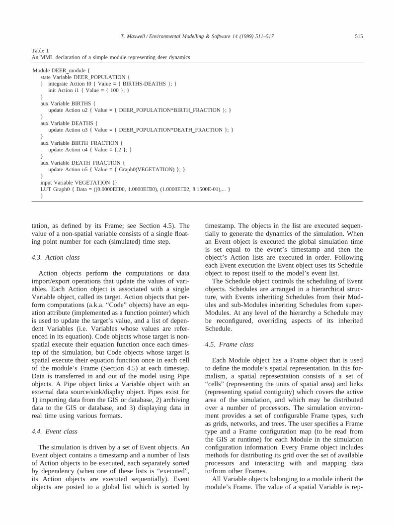
In this section we outline a parsi-model formalismwhich we call the Modular Modeling Language (MML),designed to support spatial simulation. This formalismhas been implemented and tested within the context ofour Spatial Modeling Environment (SME) (Maxwell andCostanza 1994, 1995; SME, 1995; Maxwell andCostanza, 1997a,b). As shown in the simple example inTable 1, an MML module declaration consists of anested set of object declarations. When the MML declar-ation is run through a code generator, each MML objectdeclaration is converted into a source code object declar-ation. The major classes of simulation objects includeModule, Variable, Action, Event and Frame objects. Atypical MML module specification contains only Mod-ule, Variable, and Action declarations, the Event andFrame objects are generated automatically at run time(although the Event class does exist in the MML to allowthe specification of customized Event objects). In thenext section we describe the process of automaticallygenerating the model dynamics from the MML specifi-cation. In this section we describe the major classes ofobjects used in an MML-generated simulation.
4.1. Module class
The Module object is the unit of encapsulation of themodel dynamics, i.e. a model specification consists ofan (arbitrary) number of module specifications. Modulesare designed to be self-contained archivable sub-models,which may interact with other Modules through well-defined input and output ports. Module declarations maybe nested to arbitrary depth, and Modules may inheritfrom (specialize) other Modules.
4.2. Variable class
Variable objects represent the atomic components ofa Module, i.e. each Variable corresponds to a labeled(array of) numeric quantity(s), either calculated or speci-fied as a boundary condition, called its “value” that isused to compute the model dynamics. Variables can beeither “spatial” or “non-spatial”. The value of a spatialVariable is represented by an array of floating pointvalues, with each value corresponding to a spatiallocation (i.e. a “cell” in the Module’s spatial represen-
515T. Maxwell / Environmental Modelling & Software 14 (1999) 511–517
Table 1An MML declaration of a simple module representing deer dynamics
Module DEER module {state Variable DEER POPULATION {} integrate Action I0 { Value= { BIRTHS-DEATHS }; }
init Action i1 { Value = { 100 }; }}aux Variable BIRTHS {
update Action u2 { Value= { DEER POPULATION*BIRTH FRACTION }; }}aux Variable DEATHS {
update Action u3 { Value= { DEER POPULATION*DEATH FRACTION }; }}aux Variable BIRTH FRACTION {
update Action u4 { Value= {.2 }; }}aux Variable DEATH FRACTION {
update Action u5 { Value= { Graph0(VEGETATION) }; }}input Variable VEGETATION {}LUT Graph0 { Data= ((0.0000E+00, 1.0000E+00), (1.0000E+02, 8.1500E-01),... }}
tation, as defined by its Frame; see Section 4.5). Thevalue of a non-spatial variable consists of a single float-ing point number for each (simulated) time step.
4.3. Action class
Action objects perform the computations or dataimport/export operations that update the values of vari-ables. Each Action object is associated with a singleVariable object, called its target. Action objects that per-form computations (a.k.a. “Code” objects) have an equ-ation attribute (implemented as a function pointer) whichis used to update the target’s value, and a list of depen-dent Variables (i.e. Variables whose values are refer-enced in its equation). Code objects whose target is non-spatial execute their equation function once each times-tep of the simulation, but Code objects whose target isspatial execute their equation function once in each cellof the module’s Frame (Section 4.5) at each timestep.Data is transferred in and out of the model using Pipeobjects. A Pipe object links a Variable object with anexternal data source/sink/display object. Pipes exist for1) importing data from the GIS or database, 2) archivingdata to the GIS or database, and 3) displaying data inreal time using various formats.
4.4. Event class
The simulation is driven by a set of Event objects. AnEvent object contains a timestamp and a number of listsof Action objects to be executed, each separately sortedby dependency (when one of these lists is “executed”,its Action objects are executed sequentially). Eventobjects are posted to a global list which is sorted by
timestamp. The objects in the list are executed sequen-tially to generate the dynamics of the simulation. Whenan Event object is executed the global simulation timeis set equal to the event’s timestamp and then theobject’s Action lists are executed in order. Followingeach Event execution the Event object uses its Scheduleobject to repost itself to the model’s event list.
The Schedule object controls the scheduling of Eventobjects. Schedules are arranged in a hierarchical struc-ture, with Events inheriting Schedules from their Mod-ules and sub-Modules inheriting Schedules from super-Modules. At any level of the hierarchy a Schedule maybe reconfigured, overriding aspects of its inheritedSchedule.
4.5. Frame class
Each Module object has a Frame object that is usedto define the module’s spatial representation. In this for-malism, a spatial representation consists of a set of“cells” (representing the units of spatial area) and links(representing spatial contiguity) which covers the activearea of the simulation, and which may be distributedover a number of processors. The simulation environ-ment provides a set of configurable Frame types, suchas grids, networks, and trees. The user specifies a Frametype and a Frame configuration map (to be read fromthe GIS at runtime) for each Module in the simulationconfiguration information. Every Frame object includesmethods for distributing its grid over the set of availableprocessors and interacting with and mapping datato/from other Frames.
All Variable objects belonging to a module inherit themodule’s Frame. The value of a spatial Variable is rep-
516 T. Maxwell / Environmental Modelling & Software 14 (1999) 511–517
resented by an array of floating point values, with eachvalue corresponding to a “cell” in the spatial represen-tation defined by its Frame. Spatial interactions aredefined in this formalism using relative coordinates.Relative coordinates can be either Frame-dependent orFrame-independent. For an example of Frame-dependentnotation, the statement SURFACE WATER[0][0][1]with a TIN grid Frame represents the value of SUR-FACE WATER in the cell neighboring the current cellalong the third link. For an example of Frame-independentnotation, the statement SURFACE WATER@(1,1)represents the value of SURFACE WATER in the cellone (spatial) unit to the North and one unit to the Eastof the current cell. Because of the complexity of spatialreferencing in multiple spatial representations, Actionobjects which involve complex spatial interactions aretypically constructed at the source code level using themodeling environment’s programming interface.
5. Generating model dynamics from an MMLspecification
This section outlines that process of automaticallygenerating simulation dynamics from an MML specifi-cation. As can be seen from the example in Table 1, thesimplest MML module declarations are purely declara-tive, i.e. they describe only the structure and equationsof a module, and say nothing about the execution of theequations in space and time. The space/time dynamicsof the model are generated at run-time by the modelingenvironment based on the MML specification and con-figuration information read at that time. In the rare eventthat users require greater control over the simulation thenis supplied by the configuration options then they caninclude (in the model specification) customized MMLdeclarations describing event scheduling and/or developa customized spatial representation using the modelingenvironment’s API. The steps required in generating thespatio-temporal dynamics are:
5.1. Setup model structure and dynamics
The process begins by instantiating the Module andVariable objects as declared in the MML specification.The simulation configuration information is then readfrom files and/or input directly by the user. The simul-ation dynamics are generated automatically based oninformation in the MML specification and configurationinformation read in the previous step. The Action objectsare created, starting with the Code objects declared inthe MML specification, and finishing with theinput/output Pipe objects declared in the configurationinformation. Inter-module connections are processed,and Variable dependencies are added to each Actionobject. Temporal dependencies are processed to deter-
mine the temporal variability of each Variable object.Spatial dependencies are processed to determine the spa-tial variability of each Variable object. Event objects arecreated, beginning with the global initialization Eventobject. Each Module is given a single update Event, andAction objects are added to each Event’s Action lists.The global initialization Event has a single active Actionlist, which is filled with Action objects based on initializ-ation dependencies. All Action lists are sorted by depen-dency. The frame objects are created and the Schedulesare configure hierarchically based on the informationgiven in the model configuration data. Memory is allo-cated for the spatial arrays.
5.2. Run the model
Events are initially posted to the global event list,starting with the global init event, followed by the updateevents for each Module. The Model dynamics are gener-ated by iterating the following procedure until the simul-ation end time is reached:
O The first Event is removed from the global event list.O This Event is executed (see Section 4.5).O The Event is rescheduled by posting it back to the
global event list (ordered by next execution time).
6. Example implementation: the spatial modelingenvironment
The Modular Modeling Language (MML), has beenimplemented in the context of our Spatial ModelingEnvironment (SME, see above), which has beendeveloped in an attempt to address the conceptual andcomputational complexity barriers to spatio-temporalmodel development. The MML forms the core of theSME, which links icon-based graphical modelingenvironments with parallel supercomputers and a genericobject database. This system will allow users to createand share modular, reusable model components, and util-ize advanced parallel computer architectures withouthaving to invest unnecessary time in computer program-ming or learning new systems.
The current applications of this framework include thePatuxent Landscape Model (PLM, 1995) and the Everg-lades Landscape Model (ELM, 1995). The PLM is aregional landscape simulation model that can address theeffects of different management and climate scenarioson the ecosystems in the Patuxent Watershed. Appli-cation of this model in the Patuxent watershed isexpected to allow extensive analysis of past and futuremanagement options, and will form the basis for futureapplication to other areas in the Chesapeake Bay water-shed.
517T. Maxwell / Environmental Modelling & Software 14 (1999) 511–517
7. Conclusions
We believe that effectively managing human affairsthrough the next century will require extremely complexand reliable computer models. Widespread utilization ofmodeling environments supporting graphical,hierarchical/modular design of distributed simulationswill facilitate reliable, economical model construction.General adoption of this paradigm will support thedevelopment of libraries of modules representing reus-able model components that are globally available tomodel builders, as well as making advanced computingarchitectures available to users with little computerknowledge.
References
Acock, B., Reynolds, J.F., 1990. Model structure and data base devel-opment. In: Dixon, R.K., Meldahl, R.S., Ruark, G.A., Warren,W.G. (Eds.), Process Modeling of Forest Growth Responses toEnvironmental Stress. Timber Press, Portland, OR.
Booch, G., 1994. Object-Oriented Analysis and Design. TheBenjamin/Cummins Publishing Company Inc, Redwood City, CA.
Coad, P., Yourdon, E., 1991. Object Oriented Design. Prentice Hall,Englewood Cliffs, NJ.
CORBA Object Management Group, 1996. http://www.omg.org.DMSO, 1997. High Level Architecture. http://hla.dmso.mil.ELM, 1995. Everglades Landscape Model.
http://kabir.cbl.umces.edu/Glades/ELM.html.EUROSIM Federation of European Simulation Societies, 1997
(http://ws3.atv.tuwien.ac.at/eurosim/)Forrester, J.W., 1961. Industrial Dynamics. MIT Press, Cambridge,
MA.
Gauthier, R.L., Ponto, S.D., 1970. Designing Systems Programs. Pren-tice-Hall, Englewood Cliffs, NJ.
Goodall, D. W., 1974. The Hierarchical Approach to Model Building.In: Proceeding of the First International Congress of Ecology, Wag-eningen, Center for Agricultural Publishing and Documentation.
Graham, I., 1995. Migrating to Object Technology. Addison-Wesley,Reading, Mass.
Maxwell, T., Costanza, R., 1994. Spatial ecosystem modeling in a dis-tributed computational environment. In: van den Bergh, J., van derStraaten, J. (Eds.), Toward Sustainable Development: Concepts,Methods, and Policy. Island Press, Washington, D.C, pp. 111–138.
Maxwell, T., Costanza, R., 1995. Distributed modular spatial ecosys-tem modelling. International Journal of Computer Simulation Spe-cial Issue on Advanced Simulation Methodologies 5 (3), 247–262.
Maxwell, T., Costanza, R., 1997a. A language for modular spatio-tem-poral simulation. Ecological Modeling 103, 105–113.
Maxwell, T., Costanza, R., 1997b. An open geographic modelingenvironment. Simulation Journal 68 (3), 175–185.
Modelica, 1997. Modelica: Language Design for Multi-Domain Mode-ling. http://www.dynasim.se/Modelica.
OGIS, 1996. The OpenGIS Guide. preprinthttp://ogis.org/guide/guide1.htm.
PLM, 1995. Integrated Ecological Economic Modeling.http://kabir.cbl.umces.edu/PLM.
PowerSim, The PowerSim Corp. page., 1997 (http://www.powersim.no)Richardson, G.P., 1981. Introduction to System Dynamics Modeling
with Dynamo. MIT Press, Cambridge, MA.Rogerson, D., 1997. Inside COM. Microsoft Press, Redmond, WA.Rumbaugh, J., Blaha, M. et. al., 1991. Object-Oriented Modelling and
Design. Prentice-Hall, Englewood Cliffs, NJ.Silvert, W., 1993. Object-oriented ecosystem modeling. Ecological
Modeling 68, 91–118.SME, 1995. Spatial Modeling Environment. http://kabir.cbl.umces.edu/
SME3.Webster, S., 1994. An annotated bibliography for object-oriented
analysis and design. Inf. Softw. Technol. 36 (9), 569–582.Wexelblat, R., 1981. History of Programming Languages. Academic
Press.